1
Delta DCI Series
Indoor Units
Outdoor Units
Delta 25
DCR 25 Z
Delta 35
DCR 35 Z
REFRIGERANT
REFRIGERANT
R410A
SM DELTAZ 1-E.0 GB
HEAT PUMP
NOVEMBER – 2008
CONTENTS
LIST OF EFFECTIVE PAGES
LIST OF EFFECTIVE PAGES
Note: Changes in the pages are indicated by a “Revision#” in the footer of each effected page
(when none indicates no changes in the relevant page). All pages in the following list represent
effected/ non effected pages divided by chapters.
Dates of issue for original and changed pages are:
Original ....... 0 ........ 20 November 2008
Total number of pages in this publication is 70 consisting of the following:
Page
No.
Revision
No. #
Page
No.
Revision
No. #
Page
No.
Revision
No. #
Title ....................... 0
A ........................... 0
i ............................. 0
1-1 - 1-3 ................ 0
2-1 - 2-4 ................ 0
3-1 ........................ 0
4-1 - 4-3 ................ 0
5-1 - 5-20 .............. 0
6-1 - 6-4 ................ 0
7-1 ........................ 0
8-1 ........................ 0
9-1 ........................ 0
10-1 ...................... 0
11-1-11-14............. 0
12-1-12-7 .............. 0
13-1-13-11 ............ 0
Appendix -A ...........0
•
Zero in this column indicates an original page.
SM DELTAZ 1-E.0 GB
A
CONTENTS
TABLE OF CONTENTS
Table of Contents
1.
INTRODUCTION ...................................................................................................1-1
2.
PRODUCT DATA SHEET ......................................................................................2-1
3.
RATING CONDITIONS ..........................................................................................3-1
4.
OUTLINE DIMENSIONS .......................................................................................4-1
5.
PERFORMANCE DATA & PRESSURE CURVES ...............................................5-1
6.
SOUND LEVEL CHARACTERISTICS ..................................................................6-1
7.
ELECTRICAL DATA ..............................................................................................7-1
8.
WIRING DIAGRAMS .............................................................................................8-1
9.
REFRIGERATION DIAGRAMS .............................................................................9-1
10. TUBING CONNECTIONS......................................................................................10-1
11.
CONTROL SYSTEM .............................................................................................11-1
12. TROUBLESHOOTING ..........................................................................................12-1
13. EXPLODED VIEWS AND SPARE PARTS LISTS .................................................13-1
14. APPENDIX A .........................................................................................................14-1
SM DELTAZ 1-E.0 GB
i
INTRODUCTION
1.
INTRODUCTION
1.1
General
The new Delta DC Inverter split wall mounted series comprise RC (heat pump) models,
as follows:
●
Delta 25
●
Delta 35
The indoor Delta units are available as LED display types only, featuring esthetic design,
compact dimensions, and low noise operation.
1.2
Main Features
The Delta series benefits from the most advanced innovations, namely:
● DC Inverter Technology
● R410A
● Microprocessor control.
● Infrared remote control with liquid crystal display.
● Indoor large diameter cross flow fan, allowing low noise level operation.
● Bended indoor coil with treated aluminum fins and coating for improved efficiency.
● High COP.
● Pre-Charged units up to the max allowing tubing distance.
● Heating operation at outdoor temperature down to -15ºC
● Advanced test and diagnostics mode.
● M2L diagnostics softwear cable port (for PC)
● Easy access to the interconnecting tubing and wiring connections, so that removing
the front grill or casing is not necessary.
● Refrigerant pipes can be connected to the indoor unit from 5 different optional
directions.
● Automatic treated air sweep.
● Easy installation and service.
SM DELTAZ 1-E.0 GB
1-1
CONTENTS
INTRODUCTION
1.3
Indoor Unit
The indoor unit is wall mounted, and can be easily fitted to many types of residential and
commercials applications.
It includes:
● Casing with air inlet and outlet grills.
● A large-diameter tangential fan.
● Bended coil with treated aluminum fins.
● Motorized flaps.
● Variable Speed motor (PG).
● Advanced electronic control box assembly.
● Interconnecting wiring terminal block.
● Mounting plate.
1.4
Filtration
The Delta series presents several types of air filters:
● Easily accessible, and re-usable pre-filters (mesh).
● Pre-charged electrostatic filter (optional).
● Active carbon filter (optional).
1.5
Control
The microprocessor indoor controller, and an infrared remote control, supplied as
standard, provide complete operating function and programming. For further details
please refer to the Operation Manual, Appendix A.
1.6
Outdoor Unit
The Delta outdoor units can be installed as floor or wall mounted units by using a wall
supporting bracket. The metal sheets are protected by anti- corrosion paint work allowing
long life resistance. All outdoor units are pre-charged. For further information please
refer to the Product Data Sheet, Chapter 2.
It includes :
● Compressor mounted in a soundproofed component.
Single DC Rotary ─ For DCR 25Z, DCR 35Z.
● Axial fan.
● Outdoor coil with hydrophilic louver fins.
● Outlet air fan grill.
● Display (3 LED’s).
● 2 speed AC motor.
SM DELTAZ 1-E.0 GB
1-2
CONTENTS
INTRODUCTION
1.7
Tubing Connections
Flare type interconnecting tubing to be produced on site.
For further details please refer to the Installation Manual, Outdoor Chapter 9.
1.8
Inbox Documentation
Each unit is supplied with its own installation and operation manuals, one simly remote
control manual.
1.9
Matching Table
INDOOR UNITS
OUTDOOR UNITS
MODEL
REFR”
Delta 25
DCR 25Z
R410A
√
DCR 35Z
R410A
SM DELTAZ 1-E.0 GB
Delta 35
√
1-3
CONTENTS
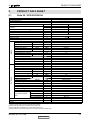
PRODUCT DATA SHEET
2.
PRODUCT DATA SHEET
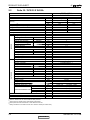
2.1
Delta 25 / DCR 25Z R410A
Model Indoor Unit
Model Outdoor Unit
Installation Method of Pipe
Characteristics
DELTA 25 DCI
DCR 25 Z R410A
Capacity (4)
OUTDOOR
INDOOR
Power input (4)
EER (Cooling) or COP(Heating) (4)
Energy efficiency class
Power supply
Rated current
Starting current
Circuit breaker rating
Fan type & quantity
Fan speeds
H/M/L
H/M/L
Air flow (1)
External static pressure
Min-Max
H/M/L
Sound power level (2)
H/M/L
Sound pressure level (3)
Moisture removal
Condenstate drain tube I.D
Dimensions
WxHxD
Weight
Package dimensions
WxHxD
Packaged weight
Units per pallet
Stacking height
Refrigerant control
Compressor type,model
Fan type & quantity
Fan speeds
H/L
Air flow
H/L
Sound power level
H/L
H/L
Sound pressure level (3)
Dimensions
WxHxD
Weight
Package dimensions
WxHxD
Packaged weight
Units per pallet
Stacking height
Refrigerant type
Refrigerant chargless distance
Additional charge per 1 meter
Liquid line
Suction line
Connections between
units
Max.tubing length
Max.height difference
Operation control type
Heating elements
Others
Units
Btu/hr
kW
kW
W/W
V/Ph/Hz
A
A
A
RPM
m3/hr
Pa
dB(A)
dB(A)
l/hr
mm
mm
kg
mm
kg
units
units
RPM
m3/hr
dB(A)
dB(A)
mm
kg
mm
kg
Units
units
kg/m
g/m
In.(mm)
In.(mm)
m.
m.
Flared
Cooling
Heating
8530(4090-10240)
8530(3410-10910)
2.5(1.2-3.0)
2.5(1.0-3.2)
0.78
0.69
3.21
3.61
A
A
220-240V ~1Ph 50/60Hz
3.5
3.1
10.5
10
Crossflow x 1
1200/1050/850
420/350/270
0
54/50/47
39/35/32
1
16
680x185x250
7
740x265x320
10
36 units per pallet
9 levels
Capillary
Rotary, TOSHIBA DA89X1C-20FZ3
Propeller(direct) x 1
830
1460
65
55
760x245x545
31
880x310x610
33
12 units per pallet
3 levels
R410A
0.85kg/7.5m
L≤10m:+0g 10<L≤15m:+200g
1/4"(6.35)
3/8"(9.53)
Max.15
Max. 10
Remote control
kW
(1)
Airflow in ducted units; at nominal external static pressure.
Sound power in ducted units is measured at air discharge.
(3)
Sound pressure level measured at 1-meter distance from unit.
(4)
Rating conditions in accordance to ISO 5151 and ISO 13253 (for ducted units).
(2)
SM DELTAZ 1-E.0 GB
2-1
CONTENTS
PRODUCT DATA SHEET
2.2
Delta 35 / DCR 35 Z R410A
Model Indoor Unit
DELTA 35 DCI
DCR 35 Z R410A
Model Outdoor Unit
Installation Method of Pipe
Characteristics
Capacity (4)
OUTDOOR
INDOOR
Power input (4)
EER (Cooling) or COP(Heating) (4)
Energy efficiency class
Power supply
Rated current
Starting current
Circuit breaker rating
Fan type & quantity
Fan speeds
H/M/L
H/M/L
Air flow (1)
External static pressure
Min-Max
H/M/L
Sound power level (2)
H/M/L
Sound pressure level (3)
Moisture removal
Condenstate drain tube I.D
Dimensions
WxHxD
Weight
Package dimensions
WxHxD
Packaged weight
Units per pallet
Stacking height
Refrigerant control
Compressor type,model
Fan type & quantity
Fan speeds
H/L
Air flow
H/L
Sound power level
H/L
H/L
Sound pressure level (3)
Dimensions
WxHxD
Weight
Package dimensions
WxHxD
Packaged weight
Units per pallet
Stacking height
Refrigerant type
Refrigerant chargless distance
Additional charge per 1 meter
Liquid line
Suction line
Connections between units
Max.tubing length
Max.height difference
Operation control type
Heating elements
Others
Units
Btu/hr
kW
kW
W/W
V/Ph/Hz
A
A
A
RPM
m3/hr
Pa
dB(A)
dB(A)
l/hr
mm
mm
kg
mm
kg
units
units
RPM
m3/hr
dB(A)
dB(A)
mm
kg
mm
kg
Units
units
kg/m
g/m
In.(mm)
In.(mm)
m.
m.
kW
Flared
Cooling
Heating
11940(4100-13640)
11940(4100-13330)
3.5(1.2-4.0)
3.5(1.2-3.9)
1.09
0.97
3.21
3.61
A
A
220-240V ~1Ph 50/60Hz
4.9
4.3
10.5
15
Crossflow x 1
1200/1000/850
550/450/350
0
56/50/46
39/33/29
1.5
16
840x185x250
8
930x265x320
11
36 units per pallet
9 levels
Capillary
Rotary, TOSHIBA DA108X1C-20FZ3
Propeller(direct) x 1
830
1460
66
56
760x245x545
32
880x310x610
34
12 units per pallet
3 levels
R410A
1.0kg/7.5m
L≤10m:+0g
10L≤20m :+200g
1/4"(6.35)
3/8"(9.53)
Max.15
Max. 10
Remote control
No
(1)
Airflow in ducted units; at nominal external static pressure.
Sound power in ducted units is measured at air discharge.
(3)
Sound pressure level measured at 1-meter distance from unit.
(4)
Rating conditions in accordance to ISO 5151 and ISO 13253 (for ducted units).
(2)
SM DELTAZ 1-E.0 GB
2-2
CONTENTS
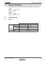
RATING CONDITIONS
3.
RATING CONDITIONS
Rating conditions in accordance with ISO 5151 and ISO 13253 (for ducted units).
Cooling:
Indoor:
27oC DB 19oC WB
Outdoor: 35 oC DB
Heating:
Indoor:
20oC DB
Outdoor: 7oC DB 6oC WB
3.1
Operating Limits
3.1.1
R410A
Indoor
Cooling
Heating
Outdoor
Upper limit 32oC DB 23oC WB
46oC DB
Lower limit 21oC DB 15oC WB
0oC DB
Upper limit 27oC DB
24oC DB 18oC WB
Lower limit 10oC DB
-15oC DB -16oC WB
Voltage
198 – 264 V
SM DELTAZ 1-E.0 GB
3-1
CONTENTS
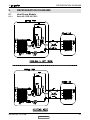
OUTLINE DIMENSIONS
4.
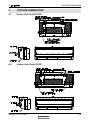
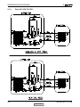
OUTLINE DIMENSIONS
4.1
Indoor Unit: Delta 25 DCI
4.2
Indoor Unit: Delta 35 DCI
SM DELTAZ 1-E.0 GB
4-1
CONTENTS
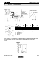
OUTLINE DIMENSIONS
4.3
Outdoor Unit: DCR 25 Z, DCR 35 Z DCI
AIR INTAKE
AIR OUTLET
SM DELTAZ 1-E.0 GB
4-2
CONTENTS
PERFORMANCE DATA & PRESSURE CURVES
5.
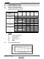
PERFORMANCE DATA
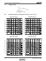
5.1
Delta 25 / DCR 25 Z R410A
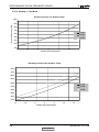
5.1.1
Cooling Capacity (kW) – Run Mode
230[V] : Indoor Fan at High Speed.
ID COIL ENTERING AIR DB/WB TEMPERATURE [oC]
OD COIL
ENTERING AIR DB
TEMPERATURE [oC]
DATA
TC
SC
PI
TC
SC
PI
TC
SC
PI
TC
SC
PI
TC
SC
PI
TC
SC
PI
0 - 20
(protection range)
25
30
35
40
46
22/15
24/17
27/19
29/21
32/23
2.41
1.67
0.59
2.30
1.63
0.66
2.18
1.59
0.73
2.07
1.55
0.80
1.93
1.50
0.88
80 - 110 % of nominal
80 - 105 % of nominal
25 - 50 % of nominal
2.57
2.73
2.89
1.71
1.74
1.77
0.60
0.61
0.62
2.46
2.62
2.77
1.67
1.70
1.73
0.68
0.67
0.69
2.34
2.66
2.50
1.63
1.77
1.69
0.78
0.74
0.76
2.23
2.54
2.39
1.59
1.62
1.65
0.81
0.82
0.83
2.09
2.25
2.41
1.54
1.57
1.61
0.89
0.90
0.91
3.05
1.81
0.63
2.93
1.77
0.70
2.82
1.73
0.77
2.70
1.69
0.84
2.56
1.64
0.92
LEGEND
TC
SC
PI
WB
DB
ID
OD
5.1.2
–
–
–
–
–
–
–
Total Cooling Capacity, kW
Sensible Capacity, kW
Power Input, kW
Wet Bulb Temp., (oC)
Dry Bulb Temp., (oC)
Indoor
Outdoor
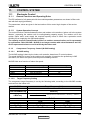
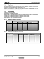
Capacity Correction Factors
Cooling Capacity Ratio Vs. Outdoor Temperature
1.20
Capacity Ratio
1.10
1.00
0.90
0.80
0.70
0.60
0.50
20
25
30
35
40
45
Outdoor Temperature [deg C]
SM DELTAZ 1-E.0 GB
5-1
CONTENTS
PERFORMANCE DATA & PRESSURE CURVES
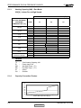
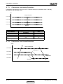
5.1.3
Heating Capacity (kW) - Run Mode
230[V] : Indoor Fan at High Speed.
ID COIL ENTERING AIR DB TEMPERATURE [oC]
OD COIL ENTERING
AIR DB/WB
TEMPERATURE [oC]
-15/-16
-10/-12
-7/-8
-1/-2
2/1
7/6
10/9
15/12
15-24
(Protection Range)
DATA
15
20
25
TC
PI
TC
PI
TC
PI
TC
PI
TC
PI
TC
PI
TC
PI
TC
PI
TC
PI
1.78
0.49
1.98
0.59
2.14
0.67
2.21
0.71
2.26
0.73
2.92
0.77
3.09
0.82
3.25
0.86
1.66
0.54
1.86
0.64
2.01
0.72
2.09
0.76
2.14
0.78
2.50
0.69
2.96
0.87
3.12
0.91
85 - 105 % of nominal
80 - 120 % of nominal
1.53
0.59
1.73
0.69
1.89
0.77
1.96
0.81
2.01
0.83
2.68
0.87
2.84
0.92
3.00
0.96
LEGEND
TC
PI
WB
DB
ID
OU
5.1.4
–
–
–
–
–
–
Total Heating Capacity, kW
Power Input, kW
Wet Bulb Temp., (oC)
Dry Bulb Temp., (oC)
Indoor
Outdoor
Capacity Correction Factors
Heating Capacity Ratio Vs. Outdoor Temperature
Capacity Ration
1.20
1.10
1.00
0.90
0.80
0.70
0.60
0.50
-15
-10
-5
0
5
10
15
Outdoor WB Temperature [deg C]
SM DELTAZ 1-E.0 GB
5-2
CONTENTS
PERFORMANCE DATA & PRESSURE CURVES
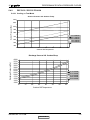
5.2
Delta 35 / DCR 35 Z R410A
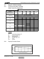
5.2.1
Cooling Capacity (kW) – Run Mode
230[V] : Indoor Fan at High Speed.
ID COIL ENTERING AIR DB/WB TEMPERATURE [oC]
OD COIL
ENTERING AIR DB
TEMPERATURE [oC]
DATA
TC
SC
PI
TC
SC
PI
TC
SC
PI
TC
SC
PI
TC
SC
PI
TC
SC
PI
-10 - 20
(protection range)
25
30
35
40
46
22/15
24/17
27/19
29/21
32/23
3.38
2.54
0.81
3.22
2.48
0.90
3.06
2.42
1.00
2.90
2.36
1.09
2.70
2.28
1.21
80 - 110 % of nominal
80 - 105 % of nominal
25 - 50 % of nominal
3.60
3.82
4.04
2.59
2.64
2.69
0.83
0.84
0.86
3.44
3.66
3.88
2.53
2.58
2.63
0.94
0.92
0.95
3.28
3.72
3.50
2.47
2.58
2.57
1.09
1.01
1.05
3.12
3.56
3.34
2.41
2.46
2.51
1.11
1.12
1.14
2.92
3.15
3.37
2.34
2.39
2.44
1.22
1.24
1.25
4.26
2.74
0.87
4.10
2.68
0.97
3.94
2.62
1.06
3.78
2.56
1.16
3.59
2.49
1.27
LEGEND
TC
SC
PI
WB
DB
ID
OD
5.2.2
–
–
–
–
–
–
–
Total Cooling Capacity, kW
Sensible Capacity, kW
Power Input, kW
Wet Bulb Temp., (oC)
Dry Bulb Temp., (oC)
Indoor
Outdoor
Capacity Correction Factors
Cooling Capacity Ratio Vs. Outdoor Temperature
1.20
Capacity Ratio
1.10
1.00
0.90
0.80
0.70
0.60
0.50
20
25
30
35
40
45
Outdoor Temperature [deg C]
SM DELTAZ 1-E.0 GB
5-3
CONTENTS
PERFORMANCE DATA & PRESSURE CURVES
5.2.3
Heating Capacity (kW) - Run Mode
230[V] : Indoor Fan at High Speed.
ID COIL ENTERING AIR DB TEMPERATURE [oC]
OD COIL
ENTERING
AIR DB/WB
TEMPERATURE
[oC]
DATA
15
20
25
2.29
0.63
2.55
0.76
2.75
0.86
2.84
0.91
2.91
0.94
3.76
0.99
3.97
1.04
4.17
1.10
2.13
0.69
2.39
0.82
2.58
0.92
2.68
0.97
2.75
1.00
3.50
0.97
3.81
1.11
4.01
1.17
85 - 105 % of nominal
1.97
0.76
2.23
0.89
2.42
0.98
2.52
1.03
2.59
1.07
3.44
1.11
3.65
1.17
3.85
1.23
15-24
TC
PI
TC
PI
TC
PI
TC
PI
TC
PI
TC
PI
TC
PI
TC
PI
TC
(Protection Range)
PI
-15/-16
-10/-12
-7/-8
-1/-2
2/1
7/6
10/9
15/12
80 - 120 % of nominal
LEGEND
TC
PI
WB
DB
ID
OU
5.2.4
–
–
–
–
–
–
Total Heating Capacity, kW
Power Input, kW
Wet Bulb Temp., (oC)
Dry Bulb Temp., (oC)
Indoor
Outdoor
Capacity Correction Factors
Heating Capacity Ratio Vs. Outdoor Temperature
Capacity Ration
1.20
1.10
1.00
0.90
0.80
0.70
0.60
0.50
-15
-10
-5
0
5
10
15
Outdoor WB Temperature [deg C]
SM DELTAZ 1-E.0 GB
5-4
CONTENTS
PERFORMANCE DATA & PRESSURE CURVES
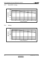
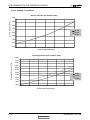
5.3
Capacity Correction Factor Due to Tubing Length
5.3.1
Delta 25 DCI : Cooling
Capacity Ratio
1.025
1.00
0.95
0.90
0.85
0.80
0.75
5.3.2
3
5
3
5
7
9
11
Tubing Length[m ]
13
15
Heating
Capacity Ratio
1.025
1.00
0.95
0.90
0.85
0.80
0.75
7
9
11
Tubing Length[m ]
SM DELTAZ 1-E.0 GB
13
15
5-5
CONTENTS
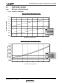
PERFORMANCE DATA & PRESSURE CURVES
Delta 35 DCI : Cooling
Capacity Ratio
5.3.3
1.025
1.00
0.98
0.96
0.94
0.92
0.90
0.88
0.84
0.80
5
7
9
11
Tubing Length[m ]
13
15
3
5
7
9
11
Tubing Length[m ]
13
15
Heating
Capacity Ratio
5.3.4
3
1.01
1.00
0.99
0.98
0.97
0.96
0.95
0.94
0.92
0.90
SM DELTAZ 1-E.0 GB
5-6
CONTENTS
PERFORMANCE DATA & PRESSURE CURVES
5.4
PRESSURE CURVES
5.4.1
DELTA 25 / DCR 25 Z R410A
5.4.1.1 Cooling => Test Mode
Suction Pressure VS.Outdoor Temp.
1200
Suction Pressure[kPa]
1100
1000
900
800
700
21/15 DB/WB
24/17 DB/WB
27/19 DB/WB
29/21 DB/WB
32/23 DB/WB
600
500
400
10
15
20
25
30
35
Outdoor DB Temperature
40
45
Discharge Pressure [kPa]
Discharge Pressure VS. Outdoor Temp.
4000
3750
3500
3250
3000
2750
2500
2250
2000
1750
1500
1250
1000
21/15 DB/WB
24/17 DB/WB
27/19 DB/WB
29/21 DB/WB
32/23 DB/WB
10
15
20
25
30
35
40
45
Outdoor DB Temperature
SM DELTAZ 1-E.0 GB
5-7
CONTENTS
PERFORMANCE DATA & PRESSURE CURVES
5.4.1.2 Heating => Test Mode
Suction Pressure VS. Outdoor Temp.
1000
Suction Pressure [kPa]
900
800
700
15 DB
600
20 DB
500
25 DB
400
300
200
-15
-10
-5
0
5
10
15
Outdoor WB Temperature
Discharge Pressure VS. Outdoor Temp.
3350
3100
2850
2600
2350
15 DB
20 DB
25 DB
2100
1850
1600
1350
1100
-15
-10
-5
0
5
10
15
Outdoor WB Temperature
SM DELTAZ 1-E.0 GB
5-8
CONTENTS
PERFORMANCE DATA & PRESSURE CURVES
5.4.2
DELTA 35 / DCR 35 Z R410A
5.4.2.1 Cooling => Test Mode
Suction Pressure VS. Outdoor Temp.
1200
Suction Pressure [kPa]
1100
1000
900
800
21/15 DB/WB
24/17 DB/WB
27/19 DB/WB
29/21 DB/WB
32/23 DB/WB
700
600
500
400
10
15
20
25
30
35
40
45
Outdoor DB Temperature
Discharge Pressure [kPa]
Discharge Pressure VS. OutdoorTemp.
4000
3750
3500
3250
3000
2750
2500
2250
2000
1750
1500
1250
1000
21/15 DB/WB
24/17 DB/WB
27/19 DB/WB
29/21 DB/WB
32/23 DB/WB
10
15
20
25
30
35
40
45
Outdoor DB Temperature
SM DELTAZ 1-E.0 GB
5-9
CONTENTS
PERFORMANCE DATA & PRESSURE CURVES
5.4.2.2 Heating =>Test Mode
Suction Pressure VS. Outdoor Temp.
Suction Pressure [kPa]
1000
900
800
700
15 DB
20 DB
25 DB
600
500
400
300
200
-15
-10
-5
0
5
10
15
Outdoor WB Temperature
Discharge Pressure VS. Outdoor Temp.
4000
Discharge Pressure [kPa]
3750
3500
3250
3000
2750
2500
15 DB
20 DB
2250
2000
25 DB
1750
1500
1250
-15
-10
-5
0
5
10
15
Outdoor WB Temperature
SM DELTAZ 1-E.0 GB
5-10
CONTENTS
SOUND LEVEL CHARACTERISTICS
6.
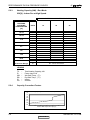
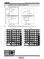
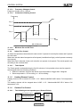
SOUND LEVEL CHARACTERISTICS
6.1
Sound Pressure Level
6.2
Figure 1. Wall Mounted
Figure 2. Floor Mounted
Figure 3. Ducted
Figure 4. Cassette
Sound Pressure Level Spectrum (Measured as Figure 1)
Delta 35
-70NC
-60NC
-50NC
-40NC
-30NC
APPROXIMATE
THRESHOLD OF
HEARING FOR
CONTINUOUS
NOISE
-20NC
MICRO BAR0.002 dB re , OCTAVE BAND SOUND PRESSURE LEVEL
MICRO BAR0.002 dB re , OCTAVE BAND SOUND PRESSURE LEVEL
Delta 25
OCTAVE BAND CENTER FREQUENCIES, [Hz]
FAN SPEED
-70NC
-60NC
-50NC
-40NC
-30NC
APPROXIMATE
THRESHOLD OF
HEARING FOR
CONTINUOUS
NOISE
-20NC
OCTAVE BAND CENTER FRQUENCIES, [Hz]
LINE
HI
ME
LO
SM DELTAZ 1-E.0 GB
6-1
CONTENTS
SOUND LEVEL CHARACTERISTICS
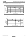
6.3
Outdoor units
Microphone Distance from Unit
6.4
Sound Pressure Level Spectrum (Measured as Figure 5)
DCR 25 Z Heating
-70NC
-60NC
-50NC
-40NC
-30NC
APPROXIMATE
THRESHOLD OF
HEARING FOR
CONTINUOUS
NOISE
-20NC
MICRO BAR0.002 dB re , OCTAVE BAND SOUND PRESSURE LEVEL
MICRO BAR0.002 dB re , OCTAVE BAND SOUND PRESSURE LEVEL
DCR 25 Z Cooling
-70NC
-60NC
-50NC
-40NC
-30NC
APPROXIMATE
THRESHOLD OF
HEARING FOR
CONTINUOUS
NOISE
Hz, BAND CENTER FREQUENCIES
Hz, BAND CENTER FREQUENCIES
DCR 35 Z Heating
-70NC
-60NC
-50NC
-40NC
-30NC
-20NC
MICRO BAR0.002 dB re , OCTAVE BAND SOUND PRESSURE LEVEL
MICRO BAR0.002 dB re , OCTAVE BAND SOUND PRESSURE LEVEL
DCR 35 Z Cooling
APPROXIMATE
THRESHOLD OF
HEARING FOR
CONTINUOUS
NOISE
-20NC
Hz, BAND CENTER FREQUENCIES
-70NC
-60NC
-50NC
-40NC
-30NC
APPROXIMATE
THRESHOLD OF
HEARING FOR
CONTINUOUS
NOISE
-20NC
Hz, BAND CENTER FREQUENCIES
SM DELTAZ 1-E.0 GB
6-2
CONTENTS
ELECTRICAL DATA
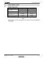
7.
ELECTRICAL DATA
7.1
Single Phase Units
MODEL
Delta 25
Delta 35
To indoor
To indoor
1PH,220-240V,50Hz
1PH,220-240V,50Hz
Max Current, A
6.3
7.5
Circuit Breaker,A
Power Supply Wiring No. X
Cross Section, mm2
Interconnecting Cable RC
Model No. X Cross Section, mm2
10
15
3x1.0 mm2
3x1.5 mm2
4x1.0 mm2
4x1.5 mm2
Power Supply
NOTE
Power wiring cord should comply with local lows and electrical regulations
requirements
SM DELTAZ 1-E.0 GB
7-1
CONTENTS
RED
BRN
BLK
N L COM
P17
FUSE
U V W
P3 P9 P11
N
BLUE
OFAN
L H
P1
2uF/450V
FAN
CAP
SM DELTAZ 1-E.0 GB
CONTENTS
N
white
gray
Blue
Brown
Y/G
Red
To metal sheet
1 2
1 2
P9
PH-12
P10
C
P22
/
P1
N
P8
1 2 3 4
P7(White)
1 2 3 4
MEGATOOL
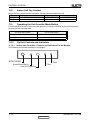
Power supply
~230V 50Hz
Blue
Brown
Y/G
Note: The dashed part is optional
JUMPER
P13
P20
FLASH
P6(White)
P2
1 2 3 4 5 6
1 2 3 4 5
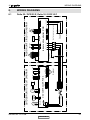
Indoor unit controller PCB
P4 red) P5(white)
M1
Delta 25 / DCR 25 Z, Delta 35 / DCR 35 Z
4/L
black
P11P15 P19P14 P3
Display
8.1
5/C
Optional
EEV
gray
P16
1uF 450V
brown
capacitor
blue
1 2 3 4 5 6
WIRING DIAGRAMS
BLUE
FERRITE CORE
1 2
P14
OCT
red
Step motor
8.
BROWN
RED
P9
1 2 3 4 5 6
1 2 3
P15
CTT
P7
8 7 6 5 4 3 2 1
1 2 3 4
P2
OMT OAT
ODU CONTROLLER PCBA
P4
1 2
REVERSE
VALVE
RED
COMP
RAT ICT
J3
YEL
GRN
J1
IFAN
J4
BLK
INDOOR UNIT CIRCUIT DIAGRAM
J2
OUTDOOR UNIT CIRCUIT DIAGRAM
WIRING DIAGRAMS
8-1
REFRIGERATION DIAGRAMS
9.
REFRIGERATION DIAGRAMS
9.1
Heat Pump Models
9.1.1
Delta 25 / DCR 25 Z DCI
SM DELTAZ 1-E.0 GB
9-1
CONTENTS
REFRIGERATION DIAGRAMS
9.1.2
Delta 35 / DCR 35 Z DCI
SM DELTAZ 1-E.0 GB
9-2
CONTENTS
TUBING CONNECTIONS
10.
TUBING CONNECTIONS
TUBE (Inch)
¼”
⅜”
½”
⅝”
¾”
11-13
13-20
11-13
40-45
13-20
11-13
60-65
18-25
11-13
70-75
18-25
11-13
80-85
40-50
11-13
TORQUE (Nm)
Flare Nuts
Valve Cap
Service Port Cap
1.
2.
3.
4.
5.
6.
7.
8.
Valve Protection Cap-end
Refrigerant Valve Port (use Allen wrench to open/close)
Valve Protection Cap
Refrigerant Valve
Service Port Cap
Flare Nut
Unit Back Side
Copper Tube
When the outdoor unit is installed above the indoor unit an oil trap is required every 5m along the suction
line at the lowest point of the riser. Incase the indoor unit is installed above the outdoor, no trap is
required.
SM DELTAZ 1-E.0 GB
10-1
CONTENTS
CONTROL SYSTEM
11.
CONTROL SYSTEM
11.1
Electronic Control
11.1.1
General Functions and Operating Rules
The DCI software is fully parametric.All the model dependent parameters are shown in Blue color
and with Italic style [parameter].
The parameters values are given in the last section of this control logic chapter of the service
manual.
11.1.2
System Operation Concept
The control function is divided between indoor and outdoor unit controllers. Indoor unit is the system
‘Master’, requesting the outdoor unit for cooling/heating capacity supply. The outdoor unit is the
system ‘Slave’ and it must supply the required capacity unless it enters into a protection mode
avoiding it from supplying the requested capacity.
The capacity request is transferred via indoor to outdoor communication, and is represented
by a parameter called ‘NLOAD’. NLOAD is an integer number with values between 0 and 127,
and it represents the heat or cool load felt by the indoor unit.
11.1.3
Compressor Frequency Control (NLOAD setting)
11.1.3.1
NLOAD setting
The NLOAD setting is done by the indoor unit controller, based on a PI control scheme.
The actual NLOAD to be sent to the outdoor unit controller, is based on the preliminary LOAD
calculation, the indoor fan speed, and the power shedding function.
NLOAD limits as a function of indoor fan speed:
Indoor Fan Speed
Low
Medium
High
Turbo
Auto
11.1.3.2
Maximum NLOAD Cooling
Max NLOADIF1C
Max NLOADIF2C
Max NLOADIF3C
Max NLOADIF4C
Max NLOADIF5C
Maximum NLOAD Heating
127
127
127
127
127
Target Frequency Setting
The compressor target frequency is set by the following table, according to the NLOAD number
received from the indoor unit.
NLOAD
Target Frequency [Hz]
0
0
0<NLOAD≤MinFreq
MinFreq
>MinFreq
MaxFreq MinFreq
{min (NLOAD, LoadDeadZone) MinFreq} MinFreq
LoadDeadZone MinFreq
Definitions
MinFreq
MaxFreq
LoadDeadZone
Cool
MinFreqC
MaxFreqC
LoadDeadZoneC
Heat
MinFreqH
MaxFreqH
LoadDeadZoneH
11-1
SM DELTAZ 1-E.0 GB
CONTENTS
CONTROL SYSTEM
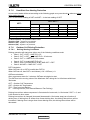
11.1.3.3
Frequency Changes Control
Frequency change rate is 1 Hz/sec.
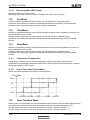
11.1.3.4
Compressor Starting Control
Frequency
Step 3
Step 2
Step 1
1
Minute
1
Minute
Time
Min 10 Minutes
11.1.3.5
Minimum On and Off Time
3 minutes.
11.1.4
Indoor Fan Control
10 Indoor fan speeds are determined for each model. 5 speeds for cool/dry/fan modes and 5 speeds
for heat mode.
When user sets the indoor fan speed to a fixed speed (Low/ Medium/ High), unit will operate constantly
at set speed.
When Auto Fan is selected, indoor unit controller can operate in all speeds. The actual speed is set
according to the cool/heat load.
11.1.4.1
Turbo Speed
The Turbo speed is activated during the first 30 minutes of unit operation when auto fan speed is
selected and under the following conditions:
Difference between set point and actual room temperature is bigger then 3 degrees.
Room temperature > 22 for cooling, or < 25 for heating.
11.1.5
Heating Element Control
Heating element can be started if LOAD > 0.8 * MaximumNLOAD AND Indoor Coil temperature
< 45.
The heating element will be stopped when LOAD < 0.5 * MaximumNLOAD OR if Indoor Coil
temperature > 50.
11.1.6
Outdoor Fan Control
11.1.6.1
The following are the speeds types (General Rules):
High Speed Output
MCU
11-2
Low Speed Output
Relay
Triac
OFAN
motor
SM DELTAZ 1-E.0 GB
CONTENTS
CONTROL SYSTEM
11.1.6.2
Speed
Controlled by
High
Low
Relay
Triac (40% to 95% effective voltage)
OFAN Operation in Cooling Mode
With keeping the OFAN general rules above in the highest priority, the operation of the OFAN will be operating
as the following:
Time After Compressor start up (minutes)
OATInitial
0 – 3min
OATInitial>20
(or Faulty)
High(Relay)
OATInitial ≤20
Low(Triac)- Open Loop
> 3min
First Time enters the
default is the last state
High (Relay)
Low (Triac)- By CDT
18
21 OAT (current)
Note: OAT faulty , use High Speed
Note:
The OATInitial value represents one OAT reading exactly at the moment start up (actual freq>0).
Low (Triac)- By OMT represents the operation of the Low Fan speed controlled by Triac
according to OMT sensor.
11.1.6.3
OFAN Operation in Heating Mode
Except to the “General rules”, the outdoor fan will always be running at High speed during heating
operation mode.
11.1.7
EEV (electronic Expansion valve) Control
EEV opening is defined as EEV = EEVOL + EEVCV
EEVOL is the initial EEV opening as a function of the compressor frequency, operation
mode, unit model and capacity.
EEVCV is a correction value for the EEV opening that is based on the compressor
temperature.
During the first 5 minutes of compressor operation EEVCV = 0.
Once the first 5 minutes are over, the correction value is calculated as follow: EEVCV(n)
= EEVCV(n-1) + EEVCTT
EEVCTT is the correction based on the compressor temperature. A target compressor
temperature is set depending on frequency and outdoor air temperature, and the actual
compressor temperature is compared to the target temperature to set the required
correction to the EEV opening.
11-3
SM DELTAZ 1-E.0 GB
CONTENTS
CONTROL SYSTEM
11.1.8
Reversing Valve (RV) Control
Reversing valve is on in heat mode.
Switching of RV state is done only after compressor is off for over 3 minutes.
11.2
Fan Mode
In high/ medium/ low indoor fan user setting, unit will operate fan in selected speed.
In AutoFan user setting, fan speed will be adjusted automatically according to the difference
between actual room temperature and user set point temperature.
11.3
Cool Mode
NLOAD is calculated according to the difference between actual room temperature and user set
point temperature by PI control.
In high/ medium/ low indoor fan user setting, unit will operate fan in selected speed.
In AutoFan user setting, fan speed will be adjusted automatically according to the calculated
NLOAD.
11.4
Heat Mode
NLOAD is calculated according to the difference between actual room temperature and user set
point temperature by PI control.
In high/ medium/ low indoor fan user setting, unit will operate fan in selected speed.
In AutoFan user setting, fan speed will be adjusted automatically according to the calculated
NLOAD.
11.4.1
Temperature Compensation
4 degrees are reduced from RT sensor temperature reading (excluding I-Feel mode), to
compensate for temperature difference between high and low areas in the heated room, and due
to coil heat radiation on RT sensor.
11.4.2
Indoor Fan Control in Heat Mode
Indoor fan speed depends on the indoor coil temperature:
ICTST ICTVL
11.5
ICTL
ICTH
ICTT
Auto Cool/Heat Mode
When in auto cool heat mode unit will automatically select between cool and heat mode according
to the difference between actual room temperature and user set point temperature (ΔT).
Unit will switch from cool to heat when compressor is off for 3 minutes, and ΔT < -3.
Unit will switch from heat to cool when compressor is off for 5 minutes, and ΔT < -3.
11-4
SM DELTAZ 1-E.0 GB
CONTENTS
CONTROL SYSTEM
11.6
Dry Mode
As long as room temperature is higher then the set point, indoor fan will work in low speed and
compressor will work between 0 and MaxNLOADIF1C Hz.
When the room temperature is lower than the set point, compressor will be switched OFF and
indoor fan will cycle 3 minutes OFF, 1 minute ON.
11.7
Protections
There are 5 protection codes.
Normal (Norm) – unit operate normally.
Stop Rise (SR) – compressor frequency can not be raised but does not have to be decreased.
HzDown1 (D1) – Compressor frequency is reduced by Down1 Hz/min.
HzDown2 (D2) – Compressor frequency is reduced by Down2 Hz/min.
Stop Compressor (SC) – Compressor is stopped.
11.7.1
Indoor Coil Defrost Protection
ICT Trend
ICT
ICT < -2
-2 ≤ ICT < 0
0 ≤ ICT < 2
2 ≤ ICT < 4
4 ≤ ICT < 6
6 ≤ ICT < 8
8 ≤ ICT
11.7.2
Fast
Increasing
SC
D1
SR
SR
Norm
Norm
Increasing
No change
Decreasing
SC
D1
SR
SR
Norm
Norm
SC
D2
D1
SR
SR
Norm
Normal
SC
D2
D2
D1
SR
SR
Fast
Decreasing
SC
D2
D2
D2
D1
SR
Indoor Coil over Heating Protection
ICT Trend
ICT
ICT > 55
53 < ICT ≤ 55
49 < ICT ≤ 53
47 < ICT ≤ 49
45 < ICT ≤ 47
43 < ICT ≤ 45
ICT ≤ 43
Fast
Decreasing
SC
D1
SR
SR
Norm
Norm
Decreasing
No Change
Increasing
SC
D1
SR
SR
Norm
Norm
SC
D2
D1
SR
SR
Norm
Normal
SC
D2
D2
D1
SR
SR
Fast
Increasing
SC
D2
D2
D2
D1
SR
11-5
SM DELTAZ 1-E.0 GB
CONTENTS
CONTROL SYSTEM
11.7.3
Compressor over Heating Protection
Compressor temperature can be in one of 5 control zones (4 in protection, and 1 normal),
according to the following chart.
CTT
Stop-Compresor
CTTOH4
P3
CTTOH3
P2
CTTOH2
P1
CTTOH1
Normal
Compressor Temperature
Increases
Else
P1
Norm
SR
P2
D1
SR
P3
D2
D1
Control Status
Stop Compressor
11.7.4
SC
Compressor over Current Protection
CCR
Stop-Compresor
CCROC4
HzDown2
CCROC3
HzDown1
CCROC2
Stop-Rise
CCROC1
Normal
11-6
SM DELTAZ 1-E.0 GB
CONTENTS
CONTROL SYSTEM
11.7.5
Heat Sink Over Heating Protection
A new control status will be set according to the following graph every one-minute or whenever when
going up by the rows.
HSTn is the current reading of HST and HSTn-1 is the last reading of HST.
HSTn
HSTn > HSTOH5
HSTOH4 ≤ HSTn < HSTOH5
HSTOH3 ≤ HSTn < HSTOH4
HSTOH2 ≤ HSTn < HSTOH3
HSTOH1 ≤ HSTn < HSTOH2
HSTn < HSTOH1
HSTn-HSTn-1
<-1
-1
0
1
>1
SC
D1
SR
SR
Norm
SC
D1
SR
SR
Norm
SC
D2
D1
SR
Norm
Norm
SC
D2
D2
D1
SR
SC
D2
D2
D1
SR
(*) Normal (Norm) – No protection status is ON.
Stop-Rise (SR) – System is in protection.
HzDown1 (D1) - System is in protection.
HzDown2 (D2) - System is in protection.
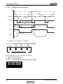
11.7.6
Outdoor Coil Deicing Protection
11.7.6.1
Deicing Starting Conditions
Deicing operation will start when either one of the following conditions exist:
Case 1: OCT <-DST – AND TLD > DI
Case 2: OCT < OATmax – 12 AND TLD > 30 minutes.
Case 3: OCT <-1 AND TLD> 100 mnutes.
Case 4: OCT is Invalid AND TLD > DI
Case 5: Unit is just switched to STBY AND OCT <-DST
Case 6: NLOAD = 0 AND OCT <-DST
DST Calculation:
When OATmax >0 or OAT is invalid; then DST=8
When OATmax ≤0; then DST= round down (-0.8 * OATmax) + 8
OATmax calculation:
After compressor starts for 3 minutes, OATmax calculation is start.
The OATmax is the moving value of the Maximum OAT during the 1st 10mintues within last
30minutes
OCT – Outdoor Coil Temperature
OAT – Outdoor Air Temperature
TLD – Time from Last Deicing
DI – Deicing Interval (Time Interval Between Two Deicing)
Deicing interval time when compressor is first started in heat mode, is 10 minutes if OCT < -2, and
is 40 minutes in other cases.
Deicing interval time is changed (increased/ decreased in 10 minutes steps) as a function of
deicing time. If deicing time is shorter then former deicing time, the deicing interval time will be
increased. If deicing time is longer then former deicing time, the deicing interval time will be
decreased.
11-7
SM DELTAZ 1-E.0 GB
CONTENTS
CONTROL SYSTEM
11.7.6.2
Deicing Protection Procedure
OCT
12
0
Threshold
COMP
ON
T1
T2
T1
max. 12 minutes
DT
HEAT
RV
T3
COOL
OFAN
T3
ON
OFF
EEVDeicerOpen
EEV
Any
T1 = DEICT1, T2 = DEICT2, T3 = DEICT3
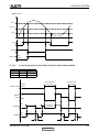
11.7.7
Condensate Water Over Flow Protection
Each of the pins P1, P2, P3 can have two options:
1 – When it is shorted with P4
0 – When it is not shorted to P4
11.7.7.1
3 Levels Logic (used in floor/ceiling models)
P2
0
1
1
0
11-8
P3
0
0
1
1
Level
L0
L1
L2&3
L4
SM DELTAZ 1-E.0 GB
CONTENTS
CONTROL SYSTEM
Water Level
LEVEL4
LEVEL2&3
LEVEL1
ON
Pump
OFF
ANY
NLOAD
0
BLINK
OPER LED NORMAL
11.7.7.2
1 Level Logic (used in all models except for floor/ceiling models)
P2
P3
Level
Don’t care
Don’t care
1
0
Normal
Overflow
Overflow when
unit is ON
Overflow
Water Level
Overflow when
unit is OFF
Normal
ON
OPER
LED
OFF
BLINK
ANY
NLOAD
NLOAD is
forced to 0
0
ON
PUMP
OFF
8 min
8 min
8 min
11-9
SM DELTAZ 1-E.0 GB
CONTENTS
CONTROL SYSTEM
11.8
Indoor Unit Dry Contact
Indoor unit Dry contact has two alternative functions that are selected by J8.
J8 = Open
J8 = Short
11.9
Function
Presence Detector Connection
Power Shedding Function
Contact = Open
No Limit
No Limit
Contact = Short
Forced to STBY
Limit NLOAD
Operating the Unit from the Mode Button
Forced operation allows to start, stop and operate in Cooling or Heating, in pre-set temperature
according to the following table:
Forced operation Mode
Pre-set Temperature
Cooling
200C
Heating
280C
11.10
On Unit Controls and Indicators
11.10.1
Indoor Unit Controller Controls and Indicators Foe All Models
The following is schematic drawing for the display:
STBY/OPER
Mode/Reset Button
Infra Red Receiver
11-10
Timer
Filter
SM DELTAZ 1-E.0 GB
CONTENTS
CONTROL SYSTEM
STAND BY
INDICATOR
OPERATION INDICATOR
1. Lights up when the Air Conditioner is connected to power and the
mode is STBY.
2. Blinks for 3 seconds, when the system is switched to Heat Mode
by using the Mode/Reset Switch on the unit (the operation
indicator will be off during this blinking time).
1. Lights up during operation mode (except for item in STBY
indicator).
2. Blinks for 300 msec., to announce that a R/C infrared
signal has been received and stored.
3. Blinks continuously during protections (according to the relevant
spec section).
4. Blinks for 3 seconds when the system is switched to Cool Mode
by using the Mode/Reset Switch on the unit.
TIMER INDICATOR
Lights up during Timer and Sleep operation.
FILTER INDICATOR
Lights up when Air Filter needs to be cleaned.
MODE / RESET BUTTON
As long as the filter Led is off, the Mode/Reset button functions as Mode
switch. Once filter Led is on, the Mode/Reset button functions as Reset
switch.
Mode Function:
Every short pressing , the next operation mode is selected, in this order:
SB → Cool Mode → Heat Mode → SB → …
In long pressing system enters diagnostic mode (refer to diagnostic
mode Sect.)
Reset Function:
For short pressing:
When Filter LED is on, it turns off the filter indicator.
Notes
1. Pressing time is defined as the time between press and release.
2. If pressing time is one second or less – press is considered as short pressing.
3. If pressing time is three seconds or longer – pressing is considered as long pressing. In
between, pressing is undetermined and system will not respond to pressing.
4. For the LED functionality during diagnostics, refer to the diagnostics Sect.
11-11
SM DELTAZ 1-E.0 GB
CONTENTS
CONTROL SYSTEM
11.10.2
Outdoor Unit Controller Indicators
Unit has three LED’s. SB LED, STATUS LED, FAULT LED.
SB LED is ON when power is ON (230 VAC),
STATUS LED is ON when COMP is ON, and Blinks according to diagnostics mode definitions
when either fault or protection occurs.
FAULT LED Blinks according to diagnostics mode definitions when either fault or protection occurs.
11.11
Jumper Settings
11.11.1
Indoor Unit Controller
11.11.1.1
Hardware Jumpers
0 = Open Jumper (disconnect jumper).
1 = Close Jumper (connect jumper).
Self test Jumper – J1
OPERATION
J1
SELF-TEST
1
NORMAL
0
Family selection Jumper – J2
Family
J2
Delta 22/25/35
Delta 50
0
1
Model selection Jumper – J3, J4
Model
A
B
C
D
11.11.1.2
J3
J4
0
0
1
1
0
1
0
1
Software Jumpers
Property
0
1
EEPROM DATA (J1)
Use ROM*
Use EEPROM
‘Thermostatic Stop- Heat’ (J2)
Deactivated
Activated
‘Heat to STBY’ (J3)
Deactivated
Activated
Enable Test Mode (J4)
Deactivated
Activated*
* Default values (used in the ROM)
Default SW jumpers according to the family (used in the ROM)
Property
‘Thermostatic Stop- Heat’ (J2)
‘Heat to STBY’ (J3)
Delta 22/25/35
Delta 50
1
1
1
1
J1 – EEPROM/ROM setting
When J1 is 1, IDU will use model/family/general parameters from EEPROM. If EEPROM is invalid, IDU will
ignore J1 and use/copy the ROM pointed by the selected jumpers (will also set an according fault).
11-12
SM DELTAZ 1-E.0 GB
CONTENTS
CONTROL SYSTEM
11.11.2
Outdoor Unit Controller
11.11.2.1
Hardware Jumpers
JP9 JUMPER LAYOUT
EEPROM Data (PIN 9)
GND
(PIN 10)
ODU3 (PIN 7)
GND (PIN 8)
ODU2 (PIN 5)
GND (PIN 6)
ODU1 (PIN 3)
GND (PIN 4)
ODU0
GND
(PIN 1)
(PIN 2)
ODU MODEL SELECTION
ODU3
ODU2
ODU1
ODU0
OFF
OFF
OFF
OFF
OFF
OFF
OFF
OFF
ON
ON
ON
ON
ON
ON
ON
ON
OFF
OFF
OFF
OFF
ON
ON
ON
ON
OFF
OFF
OFF
OFF
ON
ON
ON
ON
OFF
OFF
ON
ON
OFF
OFF
ON
ON
OFF
OFF
ON
ON
OFF
OFF
ON
ON
OFF
ON
OFF
ON
OFF
ON
OFF
ON
OFF
ON
OFF
ON
OFF
ON
OFF
ON
ODU Model
Reserved
A (Single DCR 22- Use Capillary)
B (Single DCR 25- Use Capillary)
C (Single DCR 35- Use Capillary)
D (Reserved)
E (Single DCR 22- Use EEV)
F (Single DCR 25- Use EEV)
G (Single DCR 35- Use EEV)
H
I
J
K
L
M
N
O
Compressor Type
Toshiba-DA89 (4 Poles)
Toshiba-DA89 (4 Poles)
Toshiba- DA108 (4 Poles)
Panasonic-5RS092 (6 Poles)
Panasonic-5RS092 (6 Poles)
Panasonic-5RS102(6 Poles)
PCB JUMPER SETTING FOR J2 HEAD
RXD (PIN 2)
VCC (PIN 1)
TEST (PIN 4)
N/C (PIN 3)
GND (PIN 6)
TXD100 (PIN 5)
1. Connect PIN 4 and PIN 6 to enter Buit-in-Test.
2. RXD, TXD100, VCC is for MegaTools connection.
PCB JUMPER J1 HEADER
J1 header is used for program flash.
11.11.2.2
Software Jumpers
Property
EEPROM DATA (J1)
0
Use ROM*
1
Use EEPROM
* Default values (used in the ROM)
J1 – EEPROM/ROM setting
When J1 is 1, ODU will use model/general parameters from EEPROM. If EEPROM is invalid, ODU
will ignore J1 and use/copy the ROM pointed by the selected jumpers (will also set an according
fault).
11-13
SM DELTAZ 1-E.0 GB
CONTENTS
CONTROL SYSTEM
11.12
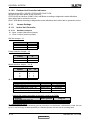
Test Mode
11.12.1
Entering Test Mode
System can enter Test mode in two ways:
Automatically when the following conditions exists for 30 minutes continuously:
o Mode = Cool, Set point = 16, Room temperature = 27±1, Outdoor temperature =
35±1
Or
o Mode = Heat, Set point = 30, Room temperature = 20±1, Outdoor temperature =
7±1
Manually when entering diagnostics with the following settings:
o Mode = Cool, Set point = 16
o Mode = Heat, Set point = 30
11.12.2
Unit Operation in Test Mode
In test mode, the unit will operate in fixed settings according to the indoor fan speed setting:
Indoor Fan Speed Setting
Unit Setting
Low
Minimum Capacity Setting
High
Nominal Capacity Setting
Auto
Maximum Capacity Setting
During test mode, protections are disabled, except for stop compressor status.
11.13
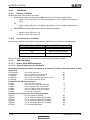
SW Parameters
11.13.1
Indoor Units SW Parameters
11.13.1.1
General Parameters for All Models:
Parameters defining the indoor fan speed as a function of Indoor Coil temperature in heat
mode (ICT):
ICTST Speed
ICTVLSpeed
ICTLSpeed
ICTHSpeed
ICTTSpeed
ICT to stop indoor fan
ICT to go down to very low speed
ICT to start in very low speed
ICT to start in increase speed from very low
ICT to enable Turbo fan speed
25
28
30
32
40
Parameters for defrost protection:
ICTDef1
ICTDef2
ICTDef3
ICTDef4
ICTDef5
ICTDef6
ICT to go back to normal
ICT to ‘stop rise’ when ICT decrease
ICT to ‘stop rise’ when ICT is stable
ICT to ‘Hz Down’ when ICT decrease
ICT to ‘Hz Down’ when ICT is stable
ICT to stop compressor
Parameters for indoor coil over heating protection:
ICTOH1
ICT to go back to normal
ICTOH2
ICT to ‘stop rise’ when ICT increase
ICTOH3
ICT to ‘stop rise’ when ICT is stable
ICTOH4
ICT to ‘Hz Down’ when ICT increase
ICTOH5
ICT to ‘Hz Down’ when ICT is stable
ICTOH6
ICT to stop compressor
11-14
8
6
4
2
0
-2
45
48
52
55
60
62
SM DELTAZ 1-E.0 GB
CONTENTS
CONTROL SYSTEM
11.13.1.2
Model Depended Parameters:
Parameter name
Models
25
35
NLOAD limits as a function of selected indoor fan speed
MaxNLOADIF1C
MaxNLOADIF2C
MaxNLOADIF3C
MaxNLOADIF4C
MaxNLOADIF5C
40
51
90
127
127
40
55
90
127
127
Indoor Fan speeds
IFVLOWC
IFLOWC
IFMEDC
IFHIGHC
IFTURBOC
IFVLOWH
IFLOWH
IFMEDH
IFHIGHH
IFTURBOH
700
850
1050
1200
1300
700
950
1050
1250
1350
NomLoadC
NomLoadH
11.13.2
700
850
1000
1200
1300
700
950
1100
1250
1300
Nominal Compressor Frequency
51
58
61
62
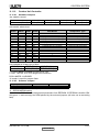
Outdoor Units SW Parameters
Parameter Name
DCR 25 Z
DCR 35 Z
Compressor Parameters
25
65
28
67
MinFreqC
MaxFreqC
MinFreqH
MaxFreqH
25
78
28
75
Step1Freq
43
45
Step2Freq
55
55
Step3Freq
63
65
Frequency limits as a function of outdoor air temperature
MaxFreqAsOATC
65
78
MaxFreqAsOAT1H
58
60
MaxFreqAsOAT2H
50
50
CTTOH1
CTTOH2
CTTOH3
CTTOH4
CTTOH5
CCR01
CCR02
CCR03
CCR04
Compressor Over Heating Protection
94
98
102
105
120
Compressor Over Current Protection [A]
35
37
39
42
Outdoor Fan Speed (RPM)
OFLOWC
OFMEDC
OFMAXC
830
94
98
102
105
120
40
42
44
47
830
11-15
SM DELTAZ 1-E.0 GB
CONTENTS
TROUBLESHOOTING
12
TROUBLESHOOTING
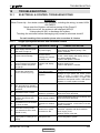
12.1
ELECTRICAL & CONTROL TROUBLESHOOTING
WARNING!!!
When Power Up – the whole outdoor unit controller, including the wiring, is under HIGH
VOLTAGE!!!
Never open the Outdoor unit before turning off the Power!!!
When turned off, the system is still charged (400V)!!!
It takes about 4 Min. to discharge the system.
Touching the controller before discharging may cause an electrical shock!!!
For safe handling of the controller please refer to section 12.3 below.
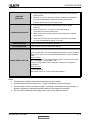
12.1.1
Single Split system failures and corrective actions
No
1
2
3
SYMPTOM
Power supply indicator (Red
LED) does not light up.
Unit does not respond to
remote control message
Unit responds to remote
control message but Operate
indicator (Green LED) does
not light up
Indoor fan does not start
(louvers are opened and
Green LED does light up)
4
5
6
7
8
9
PROBABLE CAUSE
No power supply
Remote control
message not reached
the indoor unit
Problem with display
PCB
Unit in heat mode and
coil is still not warm.
Problem with PCB or
capacitor
Indoor fan works when unit is PCB problem
OFF, and indoor fan speed is
not changed by remote control
command.
Electronics control
Compressor does not start
problem or protection
Compressor stops during
Electronic control or
operation and Green LED
power supply problem
remains on
Problem with outdoor
Compressor is on but outdoor
electronics or outdoor
fan does not work
fan
Unit works in wrong mode
(cool instead of heat or heat
instead of cool)
Electronics or power
connection to RV
CORRECTIVE ACTION
Check power supply. If power supply is OK,
check display and display wiring. if OK,
replace controller.
Check remote control batteries, if batteries
are OK, check display and display wiring, if
OK, replace display PCB.
If still not OK replace controller.
Replace display PCB.
If still not OK replace controller.
Change to cool mode and check.
Change to high speed and Check power
supply to motor is higher than 130VAC
(for triack controlled motor) or higher than
220VAC for fixed speed motors, if OK replace
capacitor, if not OK replace controller
Replace controller
Perform diagnostics (See 12.1.3 below), and
follow the actions described.
Perform diagnostics (See 12.1.3 below), and
follow the actions described.
Check outdoor fan motor according to the
procedure in section 12.2.3 below, if not OK
replace controller
Check RV power connections, if OK,
Check RV operation with direct 230VAC
power supply, if OK,
Replace outdoor controller.
All components are operating
10 properly but no cooling or no
Refrigerant leak
Check refrigeration system.
heating
SM DELTAZ 1-E.0 GB
12-1
CONTENTS
TROUBLESHOOTING
No
SYMPTOM
PROBABLE CAUSE
CORRECTIVE ACTION
Compressor is over heated
11 and unit does not generate
capacity
Units goes into protections
and compressor is stopped
with no clear reason
Compressor motor is
generating noise and no
suction occurs
Water leakage from indoor
unit
Freezing of outdoor unit in
heat mode and outdoor unit
base is blocked with ice
12
13
14
15
Unit operates with wrong fan
16
speeds or wrong frequency
12.1.2
EEV problem
Check EEV
Control problem or
refrigeration system
problem
Perform diagnostics (See 13.1.3 below), and
follow the actions described.
Phase order to
compressor is wrong
Check compressor phase order.
Indoor unit drainage
tube is blocked
Check and open drainage tube.
Connect base heater.
Wrong jumper settings
Perform diagnostics (See 12.1.3 below),
and check if units is operating by EEPROM
parameters.
Checking the refrigeration system
Checking system pressures and other thermodynamic measures should be done when system
is in Test Mode (in Test mode, system operates in fixed settings). The performance curves
given in this manual are given for unit performance in test mode when high indoor fan speed is
selected.
Entering test mode:
Set unit to Cool/16 degrees/High indoor fan speed, or Heat/30 degrees/High indoor fan speed,
and enter diagnostics.
12.1.3
Judgment by Indoor/Outdoor Unit Diagnostics
Enter diagnostics mode - press for five seconds Mode/Reset button in any operation mode.
Acknowledgment is by 3 short beeps and lights of all Display LED’s. Then, The units will enter
into Indoor and Outdoor unit diagnostic modes.
During the Outdoor unit diagnostics all three Indoor LED’s (STBY/Operate, Filter and Timer)
are blinking. When Indoor diagnostics is displayed, all three LED’s (STBY/Operate, Filter and
Timer) are ON.
When system enters diagnostics mode, only one fault code is shown. Order of priority is from
the lower to the higher number. Diagnostics is continuously ON as long as power is ON. The
current system operation mode will not be changed.
If no fault occurred in the system, no fault code will be displayed during normal operation MOde.
The last fault code will be displayed even if the system has recovered from that fault. The last
fault will be deleted from the EEPROM after the system has exit diagnostics mode.
In diagnostics mode, system fault / status will be indicated by blinking of Filter & Timer LEDs.
The coding method will be as follows:
Filter LED will blink 5 times in 5 seconds, and then will be shut off for the next 5 seconds.
Timer LED will blink during the same 5 seconds according to the following Indoor / Outdoor
unit tables:
Note: 0 – OFF, 1-ON
SM DELTAZ 1-E.0 GB
12-2
CONTENTS
TROUBLESHOOTING
12.1.3.1
Indoor unit Diagnostics
No
1
2
3
4
5
7
8
9
10
11
…
17
18
19
20
21
22
24
25
26
27
28
29
30
31
Problem
RT-1 is disconnected
RT-1 is shorted
RT-2 is disconnected
RT-2 is shorted
Reserved
Communication mismatch
No Communication
No Encoder
Reserved
Outdoor Unit Fault
Reserved
Defrost protection
Deicing Protection
Outdoor Unit Protection
Indoor Coil HP Protection
Reserved
Reserved
EEPROM Not Updated
Bad EEPROM
Bad Communication
Using EEPROM data
Model A
Model B
Model C
Model D
13.1.3.2
No.
1
2
5
4
3
2
1
0
0
0
0
0
0
0
0
0
0
0
0
0
0
0
0
1
1
1
1
0
0
0
1
1
1
0
0
0
0
0
1
1
0
0
1
0
0
1
1
1
0
1
0
1
1
0
1
0
1
1
1
1
1
1
0
0
0
0
0
0
0
0
1
1
0
1
1
0
0
1
0
1
0
1
1
1
1
1
1
1
1
1
1
1
1
1
1
1
1
1
0
0
0
0
1
1
1
1
0
0
1
1
0
0
1
1
0
1
0
1
0
1
0
1
Indoor unit diagnosis and corrective actions
Fault
Probable Cause
Check sensor connections or replace
sensor
Indoor and Outdoor controllers Replace Indoor controller
are with different versions
No Communication
Communication or
wiring is not good.
No Encoder
Indoor electronics or motor
Check motor wiring, if ok, replace motor,
if still not ok, replace Indoor controller.
Outdoor Unit Fault
Outdoor controller problem
Switch to Outdoor diagnostics.
3
grounding Check Indoor to Outdoor wiring and
grounding
4
5
6
EEPROM Not Updated System is using ROM parameters No action, unless special parameters
and not EEPROM parameters
are required for unit operation.
Bad EEPROM
No action, unless special parameters
are required for unit operation.
7
8
Corrective Action
Sensor failures of all
types
Communication
mismatch
Bad Communication
Using EEPROM data
9
Communication quality is low Check Indoor to Outdoor wiring and
reliability
grounding
No problem. System is using
EEPRRRROM parameters
SM DELTAZ 1-E.0 GB
12-3
CONTENTS
TROUBLESHOOTING
13.1.3.3
Outdoor unit Diagnostics
DCR 22 / 25 / 35 diagnostics
No
1
2
3
4
5
…
11
12
13
14
15
16
17
…
20
21
22
23
…
26
27
28
29
30
31
Problem
OCT shorted/disconnected
CTT shorted/disconnected
HST shorted/disconnected
OAT shorted/disconnected
OMT shorted/disconnected
Reserved
IPM Fault
Reserved
DC under voltage
Reserved
Zero Crossing detection fault
Mismatch between IDU & ODU models
No Communication
Reserved
Heat sink Over Heating
Deicing
Compressor Over Heating
Compressor Over Current
Reserved
Copressor Lock
Bad Communication
Missing ODU configuration
Undefined ODU Model
Outdoor Coil Overheating
Operation condition is exceeded
12.1.3.4
Fault
IPM Fault
Bad EEPROM
3
5
6
7
8
9
12.1.4
3
0
0
0
1
1
2
0
1
1
0
0
1
1
0
1
0
1
0
0
0
0
0
1
1
1
1
1
1
1
0
0
0
1
1
1
1
0
0
1
0
0
1
1
0
0
1
0
1
0
1
0
1
1
1
1
1
0
0
0
0
1
1
1
1
0
0
1
1
0
1
0
1
1
1
1
1
1
1
1
1
1
1
1
1
0
0
1
1
1
1
1
1
0
0
1
1
0
1
0
1
0
1
Probable Cause
Sensors failures of all types
2
4
4
0
0
0
0
0
Outdoor unit diagnosis and corrective actions
No.
1
5
0
0
0
0
0
DC under/over Voltage
AC under Voltage
Indoor / Outdoor unit
Communication mismatch
No Communication
Compressor Lock
Bad Communication
Corrective Action
Check sensors connections or
replace sensors.
Electronics HW problem
Check all wiring and jumper
settings,
if
OK,
replace
electronics.
No
action,
unless
special
parameters are required for unit
operation.
Electronics HW problem
Check outdoor unit power supply
voltage
Check outdoor unit power supply
voltage
Indoor and Outdoor controllers Replace Indoor controller
are with different versions
Communication or grounding Check Indoor to Outdoor wiring
wiring is not good.
and grounding
Switch unit to STBY and restart
Communication quality is low Check Indoor to Outdoor wiring
reliability
and grounding
Judgement by MegaTool
MegaTool is a special tool to monitor the system states.
Using MegaTool requires:
A computer with RS232C port.
A connection wire for MegaTool.
A special MegaTool software.
SM DELTAZ 1-E.0 GB
12-4
CONTENTS
TROUBLESHOOTING
Use MegaTool according to following procedure:
Setup MegaTool software: copy the software to the computer.
Connect RS232C port in computer with MegaTool port in Indoor/Outdoor unit controller by
the connection wire.
Run the software and choose the COM port, you can monitor the A/C system state in monitor
tab.
12.2
Simple procedures for checking the Main Parts
12.2.1
Checking Mains Voltage.
Confirm that the Mains voltage is between 198 and 264 VAC. If Mains voltage is out of this range,
abnormal operation of the system is expected. If in range check the Power (Circuit) Breaker and
look for broken or loosed cable lugs or wiring mistake(s).
12.2.2
Checking Power Input.
If Indoor unit power LED is unlighted, power down the system and check the fuse of the Indoor
unit. If the fuse is OK replace the Indoor unit controller. If the fuse has blown, replace the fuse
and power up again.
Checking Power Input procedure for the Outdoor unit is the same as with the Indoor unit.
12.2.3
Checking the Outdoor Fan Motor.
Enter Test Mode (where the OFAN speed is high)
check the voltage between two pins( Hi and N ) of connector Controller OFAN, normal voltage
is 220VAC.
12.2.4
Checking the Compressor.
The compressor is brushless permanence magnetic DC motor. Three coil resistance is same.
Check the resistance between three poles. The normal value should be below 0.5 ohm (TBD).
Pay attention U,V, Ware respective to connect to RED, BROWN, BLACK wires.
12.2.5
Checking the Reverse Valve (RV).
Running in heating mode, check the voltage between two pins of reverse valve connector,
normal voltage is 220VAC.
12.3
Precaution, Advise and Notice Items
12.3.1
High voltage in Ou0tdoor unit controller.
Whole controller, including the wires that are connected to the Outdoor unit controller may have
the potential hazard voltage when power is on. Touching the Outdoor unit controller may cause
an electrical shock.
Advise: Don’t touch the naked lead wire and don’t insert finger, conductor or anything else into
the controller when power is on.
12.3.2
Charged Capacitors
Three large-capacity electrolytic capacitors are used in the Outdoor unit controller. Therefore,
charging voltage (380VDC) remains after power down. Discharging takes about four minutes
after power is off. Touching the Outdoor unit controller before discharging may cause an electrical
shock.
12.3.3
Additional advises
When disassemble the controller or the front panel, turn off the power supply.
When connecting or disconnecting the connectors on the PCB, hold the whole housing, don’t
pull the wire.
There are sharp fringes and sting on shell. Use gloves when disassemble
SM DELTAZ 1-E.0 GB
12-5
CONTENTS
EXPLODED VIEWS AND SPARE PARTS LISTS
13.
EXPLODED VIEWS AND SPARE PARTS LISTS
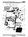
13.1
Indoor Unit: Delta 25, Delta 35 DCI
SM DELTAZ 1-E.0 GB
13-1
CONTENTS
EXPLODED VIEWS AND SPARE PARTS LISTS
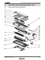
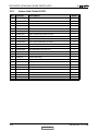
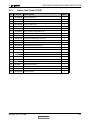
13.2
Indoor Unit: Delta 25 DCI
No.
Part No.
Description
Quan.
1
453037000
Grill A / DELTA 22,25
1
2
453100500
Grill L axis
1
3
453100600
Grill R axis
1
4
453036500
Filter for DELTA 7/9
2
7
465720000
Silk-screen front frame for Electra
1
8
4525987
SCREW COVER
3
9
453070701
Evap. System Assy./DELTA 22,25
1
10
4523526
BERAING ASSY FAN
1
11
4523523
FAN ASSY PLASTIC
1
12
452784400
IOD-7,9 Air Outlet Assy. (no wire)
1
13
4523693
DRAIN HOSE
1
14
4526659
REAR PANEL ASSY
1
15
453027400
Mount Bracket Assy./Alfa 7,9
1
16
4526000
TUBE CLIP
1
17
412040R
Remote controller RC5-RC 975-630-00
1
18
4526133
Power cord cable
1
19
4523507
Step motor
1
20
453089600
Display assy. for DELTA EHK:936-034-00
1
21
453088600
PG Resin motor 12W
1
22
453089500
DELTA DCI indoor controller EHK: 916-540-00
1
23
4525998
MOTEOR COVER
1
24
438082
Thermistor Indoor coil BLACK
1
25
4519813
Thermistor room
1
26
453027000
Terminal Cover
1
SM DELTAZ 1-E.0 GB
13-2
CONTENTS
EXPLODED VIEWS AND SPARE PARTS LISTS
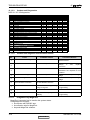
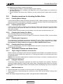
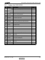
13.3
Indoor Unit: Delta 35 DCI
No.
Part No.
Description
Quan.
1
453036800
Grill A / DELTA 12
1
2
453100500
Grill L axis
1
3
453100600
Grill R axis
1
4
453082900
Filter for DELTA 12
2
7
465720001
Silk-screen front frame for Electra
1
8
4525987
SCREW COVER
3
9
453058201
Evap. System Assy./DELTA 35
1
10
4523526
BERAING ASSY FAN
1
11
4527111
FAN ASSY PLASTIC
1
12
452784401
IOD-12 Air Outlet Assy. (no wire)
1
13
4523693
DRAIN HOSE
1
14
4527186
IOD-12 REAR PANEL ASSY
1
15
453027500
Mount Bracket Assy./Alfa 12
1
16
4527512
Tube Clip
1
17
412040R
Remote controller RC5-RC 975-630-00
1
18
4526133
Power cord cable
1
19
4523507
Step motor
1
20
453089600
Display assy. for DELTA EHK:936-034-00
1
21
453088600
PG Resin motor 12W
1
22
453089500
DELTA DCI indoor controller EHK: 916-540-00
1
23
4525998
MOTEOR COVER
1
24
438082
Thermistor Indoor coil BLACK
1
25
4519813
Thermistor room
1
26
453027000
Terminal Cover
1
SM DELTAZ 1-E.0 GB
13-3
CONTENTS
EXPLODED VIEWS AND SPARE PARTS LISTS
13.4
Outdoor Unit: DСR 25 Z, DCR 35 Z R410A DCI
SM DELTAZ 1-E.0 GB
13-4
CONTENTS
EXPLODED VIEWS AND SPARE PARTS LISTS
13.5
No.
Outdoor Unit: DСR 25 Z DCI
Part No.
Description
Quan.
1
4522551
Grille A of GCN
1
2
4523441
Front panel A Painting assy
1
3
4519251
Axial Fan OD=400
1
4
467400040
Sensor/OAT & OMT
1
5
467400200
Compressor top thermistor(CTT)
1
6
467400023
Outdoor coil thermistor(OCT)
1
7
460000032R
Compressor Assy. Toshiba DA89X1C-20FZ3
1
8
453052500
PAINTING BASE ASSY.
1
9
467000001
Compressor Power Cord
1
10
4518951
4-W valve SHF-4H for R410A
1
11
4522509
4-Way valve coil
1
12
461600067
4-way valve soldering assy FOR DCR 22/25 Z
1
13
463600050
Capillary Assy FOR DCR 22/25 Z
1
14
461010004
Gas Valve 3/8" R410A
1
15
4516857
BIG SIDE COVER
1
16
461000004
Liquid Valve 1/4" R410A
1
17
464630000
Side Plate Painting Assy.
1
18
204107
Clip set PVC
1
19
4519188
4 poles terminal block
1
20
453230000
Connect Plate
1
21
464800007
Back Guard Net Painting Assy./GCZ
1
22
462300092
Condenser Assy.FOR DCR 22/25 Z R410A
1
23
453052700
PATITION
1
24
453085600
Motor Support
1
25
453085800
Connect Plate/Motor Support
1
26
4516158
Cover panel Painting assy
1
27
453031200R
Metal motor 27W
1
28
467300225R
Controller / DCR 1.6KW OMT
1
29
452841100
Earth wire
1
30
453129300
Wire UL1007 16AWG/Controller with 250 connector
1
31
453085500
Rear Plate/Left
1
SM DELTAZ 1-E.0 GB
13-5
CONTENTS
EXPLODED VIEWS AND SPARE PARTS LISTS
13.6
No.
Outdoor Unit: DСR 35 Z DCI
Part No.
Description
Quan.
1
4522551
Grille A of GCN
1
2
4523441
Front panel A Painting assy
1
3
4519251
Axial Fan OD=400
1
4
467400040
Sensor/OAT & OMT
1
5
467400200
Compressor top thermistor(CTT)
1
6
467400023
Outdoor coil thermistor(OCT)
1
7
460000033R
Compressor Assy. Toshiba DA108X1C-20FZ3
1
8
453052500
PAINTING BASE ASSY.
1
9
467000001
Compressor Power Cord
1
10
4518951
4-W valve SHF-4H for R410A
1
11
4522509
4-Way valve coil
1
12
461600068
4-way valve soldering assy FOR DCR 35 Z
1
13
463600051
Capillary Assy FOR DCR 35 Z
1
14
461010004
Gas Valve 3/8" R410A
1
15
4516857
BIG SIDE COVER
1
16
461000004
Liquid Valve 1/4" R410A
1
17
464630000
Side Plate Painting Assy.
1
18
204107
Clip set PVC
1
19
4519188
4 poles terminal block
1
20
453230000
Connect Plate
1
21
464800007
Back Guard Net Painting Assy./GCZ
1
22
462300093
Condenser Assy.FOR DCR 35 Z R410A
1
23
453052700
PATITION
1
24
453085600
Motor Support
1
25
453085800
Connect Plate/Motor Support
1
26
4516158
Cover panel Painting assy
1
27
453031200R
Metal motor 27W
1
28
467300225R
Controller / DCR 1.6KW OMT
1
29
452841100
Earth wire
1
30
453129300
Wire UL1007 16AWG/Controller with 250 connector
1
31
453085500
Rear Plate/Left
1
SM DELTAZ 1-E.0 GB
13-6
CONTENTS
APPENDIX A
APPENDIX A
INSTALLATION AND OPERATION MANUAL
►
OPERATING MANUAL DELTA 25, 35 DCI / DCR 25Z, 35Z
►
INSTALLATION MANUAL DELTA 25, 35 DCI / DCR 25Z, 35Z
14-1
SM DELTAZ 1-E.0 GB
CONTENTS