1
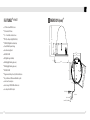
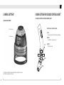
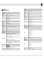
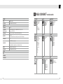
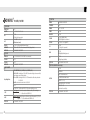
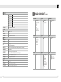
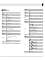
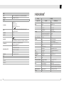
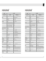
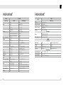
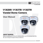
V1362DIR / V1363TIR /
V1382TIR / V1382TIRH / V1365T
Vandal Dome Camera
User Manual
5436 W Crenshaw St. Tampa, FL 33634
Tel: 866-446-3595 / 813-888-9555
Fax: 813-888-9262
www.Digital-Watchdog.com
[email protected]
Technical Support Hours: Monday-Friday
8:30am to 8:00pm Eastern Time
ABOUT MANUAL
Before installing and using the camera, please read this manual carefully.
Be sure to keep it handy for future reference.
01302012
PRECAUTIONS
TROUBSHOOTING
Do not open or modify.
■ Do not open the case except during maintenance and installation,
for it may be dangerous and can cause damages.
■ Do not put objects into the unit.
■ Keep metal objects and flammable substances from entering the camera. It can cause fire, short- circuits,
or other damages.
■ Be careful when handling the unit.
■ To prevent damages, do not drop the camera or subject it to shock or vibration.
■ Do not install near electric or magnetic fields.
■ Protect from humidity and dust.
■ Protect from high temperature.
■ Be careful when installing near the ceiling of a kitchen or a boiler room, as the temperature may rise to high levels.
■ Cleaning
To remove dirt from the case, moisten a soft cloth with a soft detergent solution and wipe.
■ Mounting Surface
The material of the mounting surface must be strong enough to support the camera.
Before sending your camera out for repair, check the items below.
If the problem persists after checking these items, contact your service
center.
■
2
No Video
Check the coaxial cable and make sure it is connected securely.
Check the lens’ iris adjustment at the menu setup of the camera.
Check the power supply and make sure the camera has the proper voltage and current.
■
Out-of-Focus Video
Check the clear dome cover and the lens for dirt or fingerprints. Use a soft cloth and gently clean.
Check the lens manual focal and zoom adjustment. Field test monitor is recommended.
■
3
FEATURES*-V1362DIR
FEATURES*-V1363TIR
■
1/3" Sony Super HAD II CCD
■
1/3” High Resolution CCD
■
540 TV Lines
■
High Resolution 560 TV Lines
■
3.3 ~ 12mm Varifocal Auto Iris Lens
■
3.3 ~ 12mm Varifocal Auto Iris Lens
■
100ft Range IR with Intelligent Camera Sync
■
Electronic Day and Night
■
Electronic Day and Night
■
100ft Range IR with Intelligent Camera Sync
■
DRC (Dynamic Range Compressor)
■
True Day and Night / TDN5
■
HME (Highlight Masking Exposure)
■
Star-Light (Super Low Light Technology)
■
SLC (Side Light Compensation)
■
DRC (Dynamic Range Compressor)
■
AGC / BLC / AWB
■
3D-DNR (3D Digital Noise Reduction)
■
Negative Imaging
■
HME (Highlight Masking Exposure)
■
Mirror Image Control
■
Negative Imaging
■
RS485 Built-In
■
AGC / BLC / AWB
■
Programmable Privacy Zone (4) & Motion Detection
■
Programmable Privacy Zone (6) & Motion Detection
■
Easy Icon Driven OSD Menu with Built-In Joystick
■
Easy Icon Driven OSD Menu with Built-In Joystick
■
Secondary Video-BNC Output
■
Auto Sensing 12VDC or 24VAC with Line Lock
■
Secondary Video-BNC Output
4
5
FEATURES*-V1382TIR
FEATURES*-V1382TIRH
■
1/3” Sony Super HAD Ⅱ CCD
■
1/3” Sony Super HAD Ⅱ CCD
■
High Resolution 560 TV Lines
■
High Resolution 560 TV Lines
■
OMNI-Focus 2.9~8.5mm 3X Motorized Zoom, Auto Iris 70ft Range IR with Intelligent Camera Sync
■
OMNI-Focus 2.9~8.5mm 3X Motorized Zoom, Auto Iris 70ft Range IR with Intelligent Camera Sync
■
True Day & Night / TDN5 (Electro Magnetic Mechanism)
■
True Day & Night / TDN5 (Electro Magnetic Mechanism)
■
Max-DR (Electronic Wide Dynamic Range)
■
Max-DR (Electronic Wide Dynamic Range)
Enables the camera to capture perfect images in both bright and dark environments simultaneously.
■
3D-DNR (3D Digital Noise Reduction)
Enables the camera to capture perfect images in both bright and dark environments simultaneously.
■
3D-DNR (3D Digital Noise Reduction)
■
HME (Highlight Mask Exposure)
Produces less noise and more color during low-light application.
Produces less noise and more color during low-light application.
■
HME (Highlight Mask Exposure)
■
SLC (Side Light Compensation)
■
SLC (Side Light Compensation)
■
DIS (Digital Image Stabilizer)
■
DIS (Digital Image Stabilizer)
■
RS485 Built-In
■
RS485 Built-In
■
Programmable Privacy Zone (6) & Motion Detection Easy Icon Driven OSD Menu with Built-In Joystick
■
Programmable Privacy Zone (6) & Motion Detection Easy Icon Driven OSD Menu with Built-In Joystick
■
Auto Sensing 12VDC or 24VAC with Line Lock
■
Auto Sensing 12VDC or 24VAC with Line Lock
■
No Fog or Condensation under Any Weather Condition
■
Built-in Heater , Withstand Temperatures as Low as -40°F
■
No Fog or Condensation under Any Weather Condition
Masks overly exposed light to produce a true video image of any environment.
6
Masks overly exposed light to produce a true video image of any environment.
7
FEATURES*-V1365T
■
1/3" Pixim Seawolf CMOS Sensor
■
690 Horizontal TV Lines
■
3.3 ~ 12mm Varifocal Auto Iris Lens
■
TDN (True Day and Night/IR Cut Filter)
■
3D-DNR (3D Digital Noise Reduction)
■
Powerful Wide Dynamic Range
■
Smear Canceling Circuit
■
AGC / BLC / AWB
■
DIS (Digital Image Stabilizer)
■
HME (Highlight Masking Exposure)
■
HME (Highlight Masking Exposure)
■
AGC / BLC / AWB
■
Programmable Privacy Zone (6) & Motion Detection
■
Easy Icon Driven OSD Menu with Built-in Joystick
■
Low Power Consumption
■
Auto Sensing 12VDC/24VAC with Line Lock
■
Secondary Video-BNC Output
DIMENSION (mm)*
103.1
109.6
41.3
91.0
85.0
6.5
145
5.0
91.0 85.0
117.0
125.0
4.5
VIDEO(yellow)
BNC JACK
DC 12V or AC24V
5mm TWIST SOLDERING
8
L= 300mm
RED
BLACK
9
INSTALLATION*
A. Loosen the Fixing Screw (D), using a screw driver.
B. Separate the Upper Case (A) and the Base (E).
C. Detach the Gimbal (C) from the Base (E).
D.Cut a hole in the ceiling for routing the cables.
F
G
DC12V
E
C
DC12V / AC24V
E.Place the Base (E) horizontally against the
ceiling and drill the screw holes at the two
marked positions.
F.Pass the Power Cable (F) and Video Cable (G)
from the camera unit through the cable hole in
the ceiling.
CONNECTION*
B
G. Align the screw holes of the camera unit with the holes in the ceiling. Secure
the camera to the ceiling with the two screws.
H. Fix Gimbal (C) to the Base (E).
I. Install and adjust the camera unit.
J.Adjust the dome liner to show the lens through
the camera window, and then x it to the Base (E).
11. Attach the Upper Case (A) with the Base (E) and A
300.0
tighten Loosen the Fixing Screw (D).
D
CAUTION : Chec k for polarit polarit y when using a DC12V power power suppl y.
10
11
CAMERA SETTING*
■ LENS ADJUSTMENT
CAMERA SETTING FOR SIDE OSD CONTROL BOARD*
: V1362DIR, V1363TIR, V1382TIR, V1382TIRH, V1365T
FUNCTIONAL OF CONTROL BOARD
1. Focus Lever
[1] SW
Functional control of O.S.D(On Screen Display)
2. Zoom Lever
[2] CON1
Second Video output connector
SW
[3] CON2
RS-485 connector
RIGHT
UP
DOWN
CON1
LEFT
CON2
1. Set the zoom level to the desired position by moving the Zoom Lever.
2. Set the focus, using the Focus Lever.
12
13
REMOTE CONTROL*-V1382TIR, V1382TIRH
■REMOTE CONTROL Instructions
Menu Access and Control
1.
Set the Camera iD in the OSD menu. The default
setting is 001. NOTE : If the Camera ID is modified,
you must reset the power for the new settings to
apply. Once you reset the power, the camera will
recognize the new Camera ID.
2.
If you press the KEY Button, the camera display
will turn into the standby image. NOTE : The LED
flicker for approximately 20 seconds.
3.
Input the same number used as the Camera ID to
the Remote Controller. After the number has been
input, the LED light will turn on, and the remote
controller will be ready to use. NOTE : The ID
number is 3 digits.
4.
The ZOOM In (+) and ZOOM Out (-) Keys are used
to control the zoom of your camera lens and to
select the zoom area of alarm function. Select the
area where you wish to observe the movement of
objects.
Zoom Function Control
Key Button
ID Buttons
Motion Alarm
ON / OFF
5.
NOTE: PRESS [KEY+ID]
(DEFAULT IS “001” FOR ID=1)
PRESS [ENT] TO ACCESS THE MENU
NOTE : THE CAMERA ID IS A 3-DIGIT NUMBER.
14
Select the zoom range by pressing the WIDE (7)
Key. Save the zoom range by pressing the TELE (8)
Key. NOTE: If the zoom range is smaller than the
alarm standby range, the zoom range setting will
not be saved.
MODULE OSD MENU*-V1362DIR
EXPOSURE
COLOR
BRIGHTNESS
SHUTTER
BLC
AGC
FUNCTION
DAY&NIGHT
WB MODE
MOTION
MIRROR
SHARPNESS
GAMMA
SLC
HME
DRC
SYNC
PRIVACY
ALARM
SETUP
SYNC
D&N MODE
MASK 1
MASK 2
MASK 3
MASK 4
COLOR SET
EXIT
CAMERA ID
TITLE EDIT
TITLE RESET
TITLE POSITION
DPC SET
LANGUAGE
PC CONT.
EXIT
SAVE & EXIT
FACTORY RESET
15
OSD MENU*-V1362DIR
EXPOSURE
FUNCTION
BRIGHTNESS
MANUAL (ELC LEVEL : 0 ~ 100) / DC (DC LEVEL : 0 ~ 31)
MIRROR
OFF/ MIRROR
SHUTTER
1/60, 1/100FLC, 1/120 ~ 1/100000
OFF / ON
BLC (Back Light Compensation)
OFF / 12dB ~ 36dB
AGC (Auto Gain Control)
EXIT / SAVE&EXIT / FACTORY SET
SHARPNESS
0 ~ 49
GAMMA
USER / 0.45 / 0.6 / 1.00
OFF / ON (0 ~ 50)
SLC (Side Light Compensation)
OFF / ON (0 ~ 55)
HME (Highlight Masking Exposure)
OFF /ON
DIS (Digital Image Stabilizer)
EXIT / SAVE&EXIT / FACTORY SET
BLC
AGC
EXIT JUMP
COLOR
SLC
HME
DIS
WB MODE
AWC / ATW / MANuAL / PUSHLOCK (AWC is recommended.)
R-Y GAIN
0 ~ 255
B-Y GAIN
0 ~ 255
EXIT JUMP
MOTION (OMNI-Plus Cameras Only)
DAY & NIGHT
Day & Night Mode
EXIT JUMP
16
OFF / ON
AUTO / COLOR / BW
COLOR---->BW : Switching from COLOR to BW; If the number is higher, the camera will only
switch during a super low light condition.
BW ---->COLOR : Switching from BW to COLOR; This number should be always lower than
COLOR to BW
Read Time :
time interval to switch from COLOR to BW
COLOR:
B&W
BURST(OFF/ON) ; When the burst is OFF, the picture will have less noise.
EXIT / SAVE&EXIT / FACTORY SET
SET WINDOW
ALL SET (Set the Entire Screen)
MOTION
EXIT JUMP
ALL CLEAR (Clear the Entire Screen)
SENSITIVITY (0 ~ 55)
SHOW INDICATOR (OFF / ICON / TRACE)
DELAY OUT(1 ~ 15)
Motion Alarm Zoom-In Delay
EXIT / SAVE&EXIT / FACTORY SET
17
MODUEL OSD MENU*-V1363TIR
EXPOSURE
PRIVACY
MASK 1
OFF / ON
MASK 2
OFF / ON
MASK 3
OFF / ON
MASK 4
OFF / ON
COLOR SET
BLACK / GRAY / COLOR 1~ 6
EXIT JUMP
EXIT / SAVE&EXIT / FACTORY SET
COLOR
BRIGHTNESS
AE PREFERENCE
BLC / HME
AGC
STARLIGHT
NIGHT-UP
DAY&NIGHT
WB MODE
R-Y GAIN
B-Y GAIN
D&N MODE
C_SUP
A_SUP
SYNC
SYNC MODE
INTERNAL / AUTO
V-PHASE
0 ~ 199
EXIT JUMP
EXIT / SAVE&EXIT / FACTORY SET
FUNCTION
SETUP
CAMERA ID
0 ~ 255
TITLE EDIT
TITLE RESET
TITLE POS.
LANGUAGE
OFF / ON
DPC ( Dead Pixel Cancellation)
English / Chinese
PC CONT.
OFF / ON
EXIT JUMP
EXIT / SAVE&EXIT / FACTORY SET
DPC
EXIT
EXIT
Exit the menu
SAVE&EXIT
Exit the menu and save the setting
FACTORY SET
Reset the menu setting to factory default
18
MOTION
MIRROR
SHARPNESS
GAMMA
FREEZE
NEGATIVE
D-ZOOM
3D DNR
DRC
SYNC
PRIVACY
MOTION
SETUP
SYNC
PRIVACY
EXIT
TITLE EDIT
PC CONTROL
LANGUAGE
MONITOR
OSD COLOR
OMNI LENS
EXIT
SAVE & EXIT
FACTORY RESET
19
OSD MENU*-V1363TIR
EXPOSURE
BRIGHTNESS
SHUTTER
BLC/HME
AGC
STARLIGHT
NIGHT-UP
EXIT JUMP
0 ~ 100
1/60 / FLK / 1/250 ~ 10000 / SENS-UP x2 ~ x256
OFF / BLC / HME
HIGH / MIDDLE / LOW / OFF
AGC(Auto Gain Control)
AUTO(x2 ~ x256) / OFF
NORMAL / HIGH
EXIT / SAVE&EXIT / FACTORY SET
COLOR
WB MODE
R-Y GAIN
B-Y GAIN
EXIT JUMP
AWC / AWT / PUSH LOCK / MANUAL / INDOOR / OUTDOOR
0 ~ 100
0 ~ 100
EXIT / SAVE&EXIT / FACTORY SET
DAY & NIGHT
Day & Night Mode
C-SUP
A-SUP
EXIT JUMP
20
AUTO : READ TIME(3~63) / S-LEVEL(0~100) / E-LEVEL(0~100)
COLOR---->BW : Switching from COLOR to BW; If the number is higher, the camera will only
switch during a super low light condition
BW ---->COLOR : Switching from BW to COLOR; This number should be always lower than
COLOR to BW
Read Time : time interval to switch from COLOR to BW
COLOR
B&W Mode : BURST (OFF / ON) There is less noise when the BURST is OFF.
SMART IR (OFF / ON)
Color Suppression : C
olor will be reduced at low illumination, if the C-SUP Level is set higher. 0 ~ 63
Aperture Suppression : The sharpness of the edges will be reduced at low illumination, if
A-SUP level is set higher. 0 ~ 15
EXIT / SAVE&EXIT / FACTORY SET
FUNCTION
MIRROR
OFF/MIRROR/V-FLIP/ROTATE
SHARPNESS
0 ~ 31
GAMMA
0.05 ~ 1.00 / USER
FREEZE
OFF / ON
NEGATIVE
OFF / ON
D-ZOOM
OFF / ON (x1.0 ~ x32 PTZ)
ON (0~100) / OFF
3D Digital Noise Reduction
3D-DNR
DRC
OFF / INDOOR / OUTDOOR
Dynamic Range Compressor
EXIT JUMP
EXIT / SAVE&EXIT / FACTORY SET
MOTION (Omni-Plus Camera Only)
MOTION
EXIT JUMP
OFF
ON
AREA SELECT (AREA 1~4)
AREA SET (POSITION / SIZE)
SENSITIVITY (0~40)
MOTION TRACE (OFF / ON)
MOTION VIEW (OFF / ON)
RETURN
EXIT / SAVE&EXIT / FACTORY SET
PRIVACY
PRIVACY
EXIT JUMP
OFF
ON
AREA SELECT (1~8)
AREA SET (POSITION / SIZE)
COLOR (0~15)
RETURN
EXIT / SAVE&EXIT / FACTORY SET
21
MODUEL OSD MENU*-V1382TIR, V1382TIRH
EXPOSURE
SYNC
SYNC
EXIT JUMP
INTERNAL / AUTO
EXIT / SAVE & EXIT / FACTORY SET
SETUP
TITLE EDIT
OFF / ON
PC CONTROL
(RS485 Control)
CAM ID / ID DISPLAY (OFF/ON) / BAUDRATE (2400 / 4800 / 9600)
The protocol is PELCO-D.
LANGUAGE
ENG / KOR / JPN / CHN1 / CHN2 / RUS / FRAN / SPAN / ITAL
MONITOR
CRT / LCD
Select LCD only if the camera is directly connected to the LCD monitor.
OSD COLOR
0 ~ 15
FUNCTION
ON
ALARM / READ TIME / ALARM ZOOM / STAND BY / RETURN
DEFECT
WHITE DEFECT CANCEL MODE
EXIT JUMP
EXIT / SAVE&EXIT / FACTORY SET
EXIT
EXIT
SAVE&EXIT
FACTORY SET
MOTION
SYNC
D&N MODE
C_SUP
A_SUP
PRIVACY
MOTION
SETUP
SYNC
22
DAY&NIGHT
WB MODE
R-Y GAIN
B-Y GAIN
MIRROR
SHARPNESS
GAMMA
FREEZE
NEGATIVE
3D DNR
D-ZOOM
SLC
HME
DIS
OFF (OMNI-Plus Camera Only)
OMNI LENS
COLOR
BRIGHTNESS
SHUTTER
BLC
AGC
MAX_DR
STARLIGHT
MASK 1
MASK 2
MASK 3
MASK 4
MASK 5
MASK 6
EXIT
CAMERA ID
TITLE
DPC
MONITOR
LANGUAGE
BAUDRATE
OMNI LENS
EXIT
SAVE & EXIT
FACTORY RESET
23
OSD MENU*-V1382TIR, V1382TIRH
EXPOSURE
BRIGHTNESS
SHUTTER
BLC
AGC
MAX_DR
STARLIGHT
EXIT JUMP
0 ~ 99
1/60, 1/100FLC, 1/120~1/100000
OFF / ON
BLC (Back Light Compensation)
HIGH / MIDDLE / LOW / OFF
AGC(Auto Gain Control)
OFF / ON (0~20) (Electronic Wide Dynamic Range)
AUTO (x2 ~ x256) / OFF (x32 is recommended for low light application.)
EXIT / SAVE&EXIT / FACTORY SET
COLOR
WB MODE
R-Y GAIN
B-Y GAIN
EXIT JUMP
AWC / ATW / MANUAL / PUSHLOCK (AWC is recommended.)
0 ~ 255
0 ~ 255
EXIT / SAVE&EXIT / FACTORY SET
FUNCTION
MIRROR
OFF/MIRROR/V-FLIP/ROTATE
SHARPNESS
0 ~ 49
GAMMA
0.05 ~ 1.00 / USER
FREEZE
OFF / ON
NEGATIVE
OFF / ON
OFF / LOW / MIDDLE / HIGH
3D DNR (3D Digital Noise Reduction)
OFF / ON(x1.0 ~ x3.0 Digital PTZ)
OFF / ON
SLC (Side Light Compensation)
3D-DNR
D-ZOOM
SLC
HME
DIS
EXIT JUMP
C-SUP
A-SUP
EXIT JUMP
24
OFF /ON
DIS (Digital Image Stabilizer)
EXIT / SAVE&EXIT / FACTORY SET
MOTION (Omni-Plus Camera Only)
DAY & NIGHT
Day & Night Mode
OFF / ON
HME (Highlight Masking Exposure)
OFF / ON
AUTO : READ TIME(3~63) / S-LEVEL(0~100) / E-LEVEL(0~100)
COLOR---->BW : Switching from COLOR to BW; If the number is higher, the camera will only
switch during a super low light condition
BW ---->COLOR : Switching from BW to COLOR; This number should be always lower than
COLOR to BW
Read Time : time interval to switch from COLOR to BW
COLOR
BW : BURST (OFF / ON); When the BURST is OFF, the picture will have less noise.
Color Suppression : C
olor will be reduced at low illumination, if the C_SUP Level is higher /
0 ~ 100. (Not available when 3D-DNR is ON.)
Aperture Suppression : Edge sharpness will be reduced at low illumination, if A_SUP Level
is higher / 0 ~ 100. (Not available when 3D-DNR is ON.)
EXIT / SAVE&EXIT / FACTORY SET
SET WINDOW
ALL SET (Set the Entire Screen)
MOTION
EXIT JUMP
ALL CLEAR (Clear the Entire Screen)
SENSITIVITY (1 ~ 120)
SHOW INDICATOR (OFF / ICON / TRACE)
DELAY OUT (1 ~ 15)
Motion Alarm Zoom-In Delay
EXIT / SAVE&EXIT / FACTORY SET
25
PRIVACY
MASK 1 OFF / ON
MASK 2 OFF / ON
MASK 3 OFF / ON
MODULE OSD MENU*-V1365T
EXPOSURE
MASK 5 OFF / ON
MASK 6 OFF / ON
EXIT JUMP
SYNC
SYNC
V-PHASE
EXIT JUMP
SETUP
CAMERA ID
TITLE EDIT
DPC
MONITOR
LANGUAGE
BAUDRATE
OMNI LENS
EXIT JUMP
EXIT
EXIT
SAVE&EXIT
FACTORY SET
26
COLOR
BRIGHTNESS
AE PREFERENCE
WDR
BLC
AGC
STARLIGHT
METER ZONE
MASK 4 OFF / ON
EXIT / SAVE&EXIT / FACTORY SET
INTERNAL / AUTO
DAY&NIGHT
WB MODE
COLOR GAIN
D&N MODE
0 ~ 199
EXIT / SAVE&EXIT / FACTORY SET
FUNCTION
0 ~ 254
OFF / ON
OFF / AUTO
DPC (Dead Pixels Cancellation)
CRT / LCD (Select LCD only if the camera is directly connected to LCD monitor.)
English / Chinese
2400 / 4800 / 9600 / 14400 / 19200 / 38400.
(The protocol is PELCO-D. It is fixed and cannot be changed.)
OFF / 1 ~ 10 (OMNI-Plus Cameras Only)
EXIT / SAVE&EXIT / FACTORY SET
Exit the menu
Exit the menu and save the setting
Reset the menu setting to factory default
MOTION
MIRROR
SHARPNESS
GAMMA
3D DNR
D-ZOOM
SYNC
PRIVACY
MOTION
SETUP
SYNC
PRIVACY
EXIT
PC CONTROL
TITLE
LANGUAGE
MONITOR
OMNI LENS
FLUORESCENT
DIGITAL VIDEO
OUT
EXIT
SAVE & EXIT
FACTORY RESET
27
OSD MENU*-V1365T
EXPOSURE
BRIGHTNESS
-48 ~ 60
AE PREFERENCE
OUTDOOR / INDOOR
BLC
OFF / BLC (PERCENTILE 10 ~ 50)
WDR
LOW / NORMAL / MEDIUM / HIGH / CUSTOM
AGC
LOW / MEDIUM / HIGH / CUSTOM
STARLIGHT
x2 ~ x64 / OFF
METER ZONE
ADJUST ZONE 1 / ADJUST ZONE 2
EXIT JUMP
EXIT / SAVE&EXIT / FACTORY SET
FUNCTION
MIRROR
OFF / MIRROR / V-FLIP / ROTATE
SHARPNESS
-8 ~ 8
GAMMA
25(0.25) ~ 100(1.0)
3D DNR
MOVIE / INFO
D-ZOOM
EXIT JUMP
ZOOM:1(x1.0) ~ 12(x8)
PAN(-100~100)/TILT(-100~100) (Digital Zoom/Pan using the camera mini joystick)
EXIT / SAVE&EXIT / FACTORY SET
MOTION
OFF / ON (ACTIVITY THR (0 ~ 255))
SET MOTION ZONES
- 1 ZONE / 1 ~ 2 ZONE / 1 ~ 3 ZONE / 1 ~ 4 ZONE
COLOR
- ADJUST ZONE 1 (MOVE/MAKES WIDE/MAKES NARROW)
WB MODE
AWC / ATW(2,000k~11,000K) / PUSH LOCK / MANUAL
(KELVIN:2,000L~11,000K /R/B:RED:-20~20 BLUE:-20~20)
COLOR GAIN
-8 ~8
- ADJUST ZONE 3 (MOVE/MAKES WIDE/MAKES NARROW)
EXIT JUMP
EXIT / SAVE&EXIT / FACTORY SET
- ADJUST ZONE 4 (MOVE/MAKES WIDE/MAKES NARROW)
MOTION
DAY & NIGHT
D&N MODE
RETURN
AUTO / AUTO(EXT) / COLOR / B&W
- AUTO Mode:(READ TIME:0~255/S-LEVEL:0~60/E-LEVEL:0~60/BW AGC:0~60)
- AUTO(EXE) Mode:(Option-IR LED Mode)
- COLOR Mode
- B&W Mode
EXIT JUMP
EXIT / SAVE&EXIT / FACTORY SET
PRIVACY
OFF
ON
BW BURST (OFF / ON)
EXIT JUMP
- ADJUST ZONE 2 (MOVE/MAKES WIDE/MAKES NARROW)
EXIT / SAVE&EXIT / FACTORY SET
PRIVACY
- AREA 1 OFF/ON
(MOVE/MAKES WIDE, MAKES NARROW)
- AREA 2 OFF/ON
(MOVE/MAKES WIDE, MAKES NARROW)
- AREA 3 OFF/ON
(MOVE/MAKES WIDE, MAKES NARROW)
- AREA 4 OFF/ON
(MOVE/MAKES WIDE, MAKES NARROW)
- AREA 5 OFF/ON
(MOVE/MAKES WIDE, MAKES NARROW)
- AREA 6 OFF/ON
(MOVE/MAKES WIDE, MAKES NARROW)
RETURN
EXIT JUMP
28
EXIT / SAVE&EXIT / FACTORY SET
29
SYNC
SYNC
INT1(SYNC to 59.64Hz)/INT2(SYNC to 60.01Hz)/LL LIMIT/V PHASE/RETURN)
EXIT JUMP
EXIT / SAVE&EXIT / FACTORY SET
SPECIFICATIONS*
Model
Camera TYPE
SETUP
PC CONTROL
TITLE
CAM ID:1 ~ 255
ID DISPLAY : OFF / ON
PROTOCOL : PELCO-D
BAUDRATE : 2400/4800/9600/19200
RETURN
OFF / ON (TITLE/ID POSITION(UP-LEFT/UP-CENTER/UP-RIGHT/DOWN-LEFT/
DOWN-CENTER/DOWN-RIGHT)
LANGUAGE
ENGLISH
MONITOR
CRT / LCD
OFF
OMNI LENS
FLUORESCENT
ON ALARM OFF
ALARM ON(READ TIME(5~15)/ALARM ZOOM(4~214)/STAND BY(0~214)/RETURN)
OFF / CRR(Manual Lens, Color Rolling/Flickerless Mode)/
CRR2(DC Lens, Color Rolling Mode)
Image
Scanning
Min. Scene Illumination
Functions
DIGITAL OUT (OFF / ON)
DIGITAL VIDEO OUTPUT
FIELD ORDER (NORMAL / REVERS)
FRAME RPT (OFF / 2X / FREEZE)
RETURN
EXIT JUMP
EXIT
EXIT
SAVE & EXIT
FACTORY SET
EXIT / SAVE&EXIT / FACTORY SET
Lens
Resolution
Video Output
S/N Ratio
OSD
Environmental Conditions
Power
Physical Specification
IP Rating
30
V1362DIR
Color/BW
Mount
Device
Size
Pixels-Total
Pixels-Effective
System
Horizontal Frequency Internal Mode
Vertical Frequency Internal Mode
IR-LED On
BLC
AGC
AWB
Mirror
Motion Detection
Privacy Zone
Focal Length
Horizontal
VBS 1.0Vp-p
S/N Ratio
OSD
Operating Temperature
Humidity
Power Requirement
Power Consumption
Dimensions(φ x H)
IP66
Vandal Dome Camera
Surface
Super HAD II CCD
1/3"
811(H) x 508(V)
768(H) x 494(V)
525 line, 2:1Interlace
15,734Hz
59.94Hz
0.0 Lux
ON / OFF (Area Setting)
ON / OFF (Gain Adjust)
ATW / AWC / MANUAL / PUSH LOCK
ON / OFF
ON / OFF
4 Programmable Zone / Size
3.3 ~ 12mm Varifocal Auto Iris Lens
540 TV Lines
VBS 1.0Vp-p(75 Load)
50dB
YES
-10oC ~ +55oC(14oF ~ 131oF)
Less than 90%
12VDC / 24VAC
12VDC: 1.96W, 163.3mA / 24VAC: 2.2W, 91.7mA
12VDC: 4.4W, 366.7mA / 24VAC: 3.0W, 125mA (LED ON)
109.6 X 145mm, 4.31 X 5.71in
31
SPECIFICATIONS*
Model
Camera TYPE
Image
Scanning
Min. Scene Illumination
Functions
Lens
Resolution
Video Output
S/N Ratio
OSD
Environmental Conditions
Power
Physical Specification
IP Rating
32
SPECIFICATIONS*
V1363TIR
Color/BW
Vandal Dome Camera
Mount
Size
Pixels-Total
Pixels-Effective
System
Horizontal Frequency Internal Mode
Horizontal Frequency Line-Lock Mode
Vertical Frequency Internal Mode
Vertical Frequency Line-Lock Mode
IR-LED On
STAR-LIGHT
3D-DNR
AGC
AWB
Motion Detection
Privacy Zone
Focal Length
Horizontal
VBS 1.0Vp-p
S/N Ratio
OSD
Operating Temperature
Humidity
Power Requirement
Power Consumption
Surface
1/3" High Resolution CCD
811(H) x 508(V)
768(H) x 494(V)
525 line, 2:1Interlace
15,734Hz
15.750Hz
59.94Hz
60Hz
0.0 Lux
ON / OFF (Area Setting)
ON / OFF (Gain Adjust)
OFF / LOW / MIDDLE / HIGH
ATW / AWC / INDOOR / OUTDOOR / MANUAL / PUSHLOCK
OFF / ON (Area / Sensitivity)
8 Programmable Zone / Size
3.3 ~ 12mm Varifocal Auto Iris Lens
560 TV Lines
VBS 1.0Vp-p(75 Load)
52dB
YES
-10oC ~ +55oC(14oF ~ 131oF)
Less than 90%
12VDC / 24VAC
12VDC: 1.96W, 163.3mA / 24VAC: 2.2W, 91.7mA
12VDC: 4.4W, 366.7mA / 24VAC: 3.0W, 125mA (LED ON)
109.6 X 145mm, 4.31 X 5.71in
Dimensions(φ x H)
IP66
Model
Camera TYPE
Image
Scanning
Min. Scene Illumination
Functions
Lens
Resolution
Video Output
S/N Ratio
OSD
Environmental Conditions
Power
Physical Specification
IP Rating
V1382TIR
Color/BW
Mount
Device
Size
Pixels-Total
Pixels-Effective
System
Horizontal Frequency Internal Mode
Vertical Frequency Internal Mode
IR-LED On
EWDR
STAR-LIGHT
3D-DNR
DIS
Motion Detection
Privacy Zone
Focal Length
Horizontal
VBS 1.0Vp-p
S/N Ratio
OSD
Operating Temperature
Humidity
Power Requirement
Power Consumption
Dimensions(φ x H)
IP66
Vandal Dome Camera
Surface
Super HAD II CCD
1/3"
811(H) x 508(V)
768(H) x 494(V)
525 line, 2:1Interlace
15,734Hz
59.94Hz
0.0 Lux
ON / OFF
ON / OFF (x2 ~ x256)
OFF / LOW / MIDDLE / HIGH
ON / OFF
ON / OFF (Area / Sensitivity)
6 Programmable Zone / Size
2.9 ~ 8.5mm OMNI-Focus Lens
580 TV Lines
VBS 1.0Vp-p(75 Load)
50dB
YES
-10oC ~ +55oC(14oF ~ 131oF)
Less than 90%
12VDC / 24VAC
12VDC: 1.96W, 163.3mA / 24VAC: 2.2W, 91.7mA
12VDC: 4.4W, 366.7mA / 24VAC: 3.0W, 125mA (LED ON)
109.6 X 145mm, 4.31 X 5.71in
33
SPECIFICATIONS*
Model
Camera TYPE
Image
Scanning
Min. Scene Illumination
Functions
Lens
Resolution
Video Output
S/N Ratio
OSD
Environmental Conditions
Power
Physical Specification
IP Rating
34
SPECIFICATIONS*
V1382TIR
Color/BW
Mount
Device
Size
Pixels-Total
Pixels-Effective
System
Horizontal Frequency Internal Mode
Vertical Frequency Internal Mode
IR-LED On
EWDR
STAR-LIGHT
3D-DNR
DIS
Motion Detection
Privacy Zone
Focal Length
Horizontal
VBS 1.0Vp-p
S/N Ratio
OSD
Operating Temperature
Humidity
Power Requirement
Power Consumption
Dimensions(φ x H)
IP66
Surface
Super HAD II CCD
1/3"
811(H) x 508(V)
768(H) x 494(V)
525 line, 2:1Interlace
15,734Hz
59.94Hz
0.0 Lux
ON / OFF
ON / OFF (x2 ~ x256)
OFF / LOW / MIDDLE / HIGH
ON / OFF
ON / OFF (Area / Sensitivity)
6 Programmable Zone / Size
2.9 ~ 8.5mm OMNI-Focus Lens
580 TV Lines
VBS 1.0Vp-p(75 Load)
50dB
YES
-40oC ~ +55oC(-40oF ~ 131oF)
Less than 90%
12VDC / 24VAC
12VDC: 1.96W, 163.3mA / 24VAC: 2.2W, 91.7mA
12VDC: 4.4W, 366.7mA / 24VAC: 3.0W, 125mA (LED ON)
109.6 X 145mm, 4.31 X 5.71in
V1365T
General Spec
Model
Vandal Dome Camera
CCD Type
Total number of pixels
Minimum Illumination
Resolution
Voltage
Power Consumption
1/3" 420K Pixels Color
768(H) X 548(V)
0.22Lux (F1.2, 30IRE-COLOR)
0.0Lux (LED ON)
H: 690 TV Lines Effective
Electric Spec
DC 12[V] (11.0[V] ~ 20.0[V])
AC 24[V] (20.0[V] ~ 30.0[V])
DC12V-3.1W / AC24V-3.2W
COMMON
General Spec
Shutter speed
S/N Ratio
Gamma
Sync System
AWB
Mirror
Motion Detection
Privacy Zone
Operation Temperature
Storage Temperature
Operation Humidity
Mechanical Spec
-10℃ ∼ +50℃ (14oF ~ 131oF)
-20℃ ∼ +70℃
Under 90% (Non-condensing)
ATW / AWC / MANUAL / PUSH LOCK
ON / OFF
ON / OFF
4 Programmable Zone / Size
35
WARRANTY INFORMATION*
LIMITS AND EXCLUSIONS*
Digital Watchdog (referred to as “the Warrantor”)
warrants the Camera Series against defects in
materials or workmanship as follows.
There are no express warranties except as listed above.
The Warrantor will not be liable for incidental or consequential
damages, including without limitation and damage to recording media,
resulting from the use of these products or arising out of any breach
of the warranty. All express and implied warranties, including the
warranties of merchantability and fitness for particular purpose,
are limited to the applicable warranty period set forth above.
LABOR : For the initial five (5) years from the date of original purchase,
if the camera is determined to be defective,
the Warrantor will repair or replace the unit, with new or refurbished
product at its option, at no charge.
PARTS : In addition, the Warrantor will supply
replacement parts for the initial five (5) years.
To obtain warranty or out of warranty service,
please contact a Technical Support Representative at
1-866-446-3595 Monday through Friday from 8:30AM to 8:00PM Eastern.
A purchase receipt or other proof of the original purchase date is required
before warranty service is rendered. This warranty only covers failures due to
defects in materials and workmanship which arise during normal use.
This warranty does not cover damage which occurs in shipment or failures
which are caused by products not supplied by the Warrantor or failures
which result from accident, misuse, abuse, neglect, mishandling,
misapplication, alteration, modification, faulty installation, set-up adjustments,
improper antenna, inadequate signal pickup, maladjustment of consumer controls,
improper operation, power line surge, improper voltage supply, lightning damage,
rental use of the product or service by anyone other than an authorized repair
facility or damage that is attributable to acts of God.
36
Some states do not allow the exclusion or limitation of incidental
or consequential damages, or limitations on how long an implied
warranty lasts, so the above exclusions or limitations may not
apply to you. This warranty gives you specific legal rights, and you
may also have other rights that vary from state to state.
If the problem is not handled to your satisfaction,
then write to the Address listed on the next page.
Service calls which do not involve defective materials or
workmanship as determined by the Warrantor, in its sole
discretion, are not covered. Costs of such service calls are
the responsibility of the purchaser.
37