1
Errata
54510A Digitizing Oscilloscope Front-Panel
Title & Document Type: Reference Manual
Manual Part Number: 54510-90901
Revision Date: December 1, 1990
HP References in this Manual
This manual may contain references to HP or Hewlett-Packard. Please note that HewlettPackard's former test and measurement, semiconductor products and chemical analysis
businesses are now part of Agilent Technologies. We have made no changes to this
manual copy. The HP XXXX referred to in this document is now the Agilent XXXX.
For example, model number HP8648A is now model number Agilent 8648A.
About this Manual
We’ve added this manual to the Agilent website in an effort to help you support your
product. This manual provides the best information we could find. It may be incomplete
or contain dated information, and the scan quality may not be ideal. If we find a better
copy in the future, we will add it to the Agilent website.
Support for Your Product
Agilent no longer sells or supports this product. You will find any other available
product information on the Agilent Test & Measurement website:
www.tm.agilent.com
Search for the model number of this product, and the resulting product page will guide
you to any available information. Our service centers may be able to perform calibration
if no repair parts are needed, but no other support from Agilent is available.
Front-Panel
Reference
HP 54510A
l GSa/s Digitizing osci1loscope
И 輩脚 :
@CopyrightHewlett-PackardCompany1990
HP Part Number 54510‐ 90901
Printed in thc UosA. Dcccmbcr 1990
Herstcl|crtcsc.hetnigung
Hiermit wird bescheinigt,dqB dasGer6VSystem
HP545104
in Ubereinstimmungmit den gsstimmungenvon PostverfiigunglWU
funkentsttirtist.
Der DeutschenBundespostwurde dasInverkehrbringendieses
GeriteVsystemsangezeigtund die Berechtigungzur Uberpriifung der
Serieauf Einhalnng der Bestimmungeneingeriiumt.
Zusatzinformationfiir Mep- und Testgerite
WerdenMeB- und Testgeritemit ungeschirmten
Kabelnund/oderin
offenenMepaufbautenverwendet,so ist vom Betreibersicherzustellen,
daBdie Funk-Entstil6sslimmupgen
an seiner
unter Betriebsbedingungen
Grundstiicksgren:ze
eiagehaltenwerden.
Manufacturer'sdeclaration
This is to certifythat this productmeetsthe radio frequencyinterference
requirementsof directiveL046,I8y'..
The GermanBundesposthasbeen
notifiedthat this equipmentwasput into circulationand wasgrantedthe
right to checkthe product tlpe for compliancewith theserequirements.
Additional Informationfor Test-and MeasurementEquipment
Note: If testand measurement
equipmentis operatedwith unshielded
cablesand/orusedfor measurements
on openset-ups,the usermust
insurethat undertheseoperatingconditions,the radio frequency
interferencelimits are met at the border of his oremises.
Product
Warranty
This Hewlen-Packardproduct hasa warranty againstdefectsin material
and workmanshipfor a period of three yearsfrom date of shipment.
During warrantyperio4 Hewle$-PackardCompanywi[ at is option,
either repair or replaceproductsthat prove to be defective.
For warrantyserviceor repair, this product mustbe returned to a service
facility designatedby Hewlen-Packard. However,warranty servicefor
products installedby Hewlett-Packardand certain other products
desipated by Hewlett-Packardwill be performed at the Buyer'sfacility at
no chargewithin the Hewlett-Packardservicetravel area. Outside
Hewlett-Packardservicetravel areas,warrantyservicewill be performed
at the Buyer'sfacility only upon Hewlett-Packard'sprior agreenent and
the Buyer shall payHewlett-Packard'sround trip travel e4penses.
For products returned to Hewlett-Packardfor warranty service,the Buyer
shall prepay shippi"g chargesto Hewlett-Packardand Hewlett-Packard
shall pay shippragchargesto return the product to the Buyer. tlowever,
the Buyer shall pay all shippingcharges,duties,and taxesfor products
returned to Hewlett-Packardfrom anothercountry.
Hewlett-Packardwarrantsthat its softwareand firmware desipated by
Hewlett-Packardfor usewith an instrumentwill executeits program'ning
instructionswhen properly installed on that instrnrnent. Hewlett-Packard
doesnot warrant that the operation of the instrumentsoftware,or
firmwarewill be uninterruptedor error free.
Umitrationof Wananty The foregoingwarranty shallnot apply to defectsresultingfrom improper
or inadequatemaintenanceby the Buyer,Buyer-suppliedsoftu/areor
interfacing,unauthorizedmodification or ''risuse,operation outsideof the
for the product,or impropersitepreparation
environmentalspecifications
or maintenance.
NO OTHER WARRANTY IS EXPRESSEDOR IMPLIED.
HEWLETT-PACKARD SPECIFICALLY DISCI-AIMS THE
IMPLIED WARRANTIES OR MERCHANTABILITY AND FITNESS
FOR A PARTICUT-ARPURPOSE.
Exc:usive nemedies THE REMEDIES PROVIDED HEREIN ARETHE BUYER'SSOE
PACKARD SHALL
AND EXCLUSM REMEDIFQ.HEWLET‐
REσ ,SPECIAL
NOT BE LIABLE FOR ANY DIRECr,IND】
層圧打HER
いL DAMAGES,Ч
INCIDENTAI.OR CONSEQUEN口
BASED ON CONrRACr,TORT,OR ANY OTHER LEGAL
THEORY.
Asgistance
Product naintenance agreementsand other customerassistance
agreementsare availablefor Hewlett-Packardproducts.
For any assistance,contactyour nearestHewlett-PackardSalesand
ServiceOffice.
Certification
Safety
Hewlett-PackardCompanycertifies 1f,31thisproduct met is published
specificationsat the time of shipmentfrom the faclory. Hewlett-Packard
further certi.fiesthat its calibration measurementsare traceableto the
United StatesNational Bureau of Standards,to the extentallowedby the
Bureau'scalibration facility, and to the calibration facilities of other
International StandardsOrganizationnembers.
This product hasbeendesignedand testedaccordingto International
SafetyRequirements. To ensuresafeoperation and to keepthe product
safe,the information, cautions,and warningsin this manualmustbe
heeded.
Gontents
Chapter l
:ntrodu●ing the HP 54510A
htroduction.…
Chapter 2
.¨ .¨ .¨ .¨ ・… … ・… … ・… … ・… … … … ・… … … …1‐
1
Instrument
Setup
Introduction
InitialInspection
.. .
Contents
of Shipment
AvailableAccessories
OperatingEnvironment.....
Storageand Shipping
RearPanel
PowerRequirements
.. .. .
SelectingLine Voltage
VerifyingtheFuse
PowerCord .
Line Switch
IntensityControl
Air FlowRequirements
ConnectingE:rternalEquipment
Chapter3
F『ont‐Pane:Over宙
.......2-L
.......2-t
.....2-t
.........2-2
.....2-2
. ..2-2
........2-3
.......2-3
. . .24
......2-5
...2-5
....2-5
.......2-7
... ....L7
...2-B
ew
lntroductlon to
thc Front Panel.…… … … … … … … … … … …… … … … … … … … … …3‐
1
… … … … … … … … … … … … …… … … … … … … ・
S y s t c m C o n t r o l .……
2
3‐
… … … …… … …… 。… … … ・・… … … … … … …3‐
RUN/STOP Key.…
2
..… … …・・… … ・… … … … … … … … ・… ・・… 。
.…
SINGLE Key.…
3‐
3
C L E A R D I S P L A Y K e y . … … … … … … … … … … … … … … … ……3 ‐
3
・・・・・・・・・・・・・・・・・・・・・・・・・・・・・・・・・・・・
LOCAL Kcy ........・
3‐
3
…………………………………………………。
HARDCOPY Key。
33
4
Setup … … ..… ・・・・・・…・… ・・・・・・・・・・・・・・・・・・・・・・・・・・・・・・・・・・。
3‐
…… … … … … … … … … … … … … … … ¨ …3 ‐
AttOSCALE Key.…
5
・・・・・・・・・・・・・・・・・・・・・・・・・・・・・・・・・・・
RECALL Kcy ........・
3‐
5
SAVE】 くey ......・・・・・・・・・・・・・・・・・・・・・・・・・・・・・・・・・・・・・・・・・
3‐
6
… … … … … … … …… … … … … … … … … … … … … ・
SHOW Key.…
3‐
6
Menus .… .… .… … ・…・・・・・・・… ・・… ・・・・・・・・・・… ・・・・・・・・・・・・・・
3‐
7
HP 54510A
Front‐Panel Reference
Contents.t
E n t r y.
NumericKelpad
Ituob.
FINEKey
I n p u t.
Display
InstrumentReset.
Chapter4
Timebase
Menu
IntroductiontotheTimebase
..
Time/DivKey
delayKey
referenceKey . .
repetitive/
realtimeKey..
r e p e t i t i vmeo d e.
realtimemod
.e
MemoryBarExercise
$ingleShotExercise
$ingleShotin RepetitiveMode .
$ingleShotin RealTine Mode
Panand Taom .
Panand Zoom Exercise
Zooning
Panning
Chapter5
...+L
........1-1
...+3
.. .$3
.....+4
.........U
........u
.....+5
......+8
. . . . . . .+8
. .. . . . .4-11
..+L2
..+L2
.......+13
......+15
ChannelMenu
IntroductiontoChannels
CHANNELKey..
VerticalSensitivityKey..
offsetKey
CouplingKey..
Inputlmpedance.
moreKey
probekey
ECLKey
TTLKey
Contents-2
...............38
........98
.......19
.........19
.....t9
....110
....3-11
.........5-1
.......5-2
.........5-2
........5-2
..........5-3
........5-3
.........5-4
........5-4
.........5-5
...5-5
HP54510A
Front-PanelReference
Ghapter6
HP 54510A
Front-Panel Reference
Trigger Menu
Introduction to the Triggers
TriggerModelnteraction.
EdgeTriggerMode.
trig'd/autoKey. ..
sourceKey..
levelKey
slopeKey
noiserejectKey..
holdoffKey
HoldoffExercise
..
Instru'nentSetup
.
OscilloscopeSetup.
PatternTriggerMode.
patternKey..
whenKey
holdoffKey
PatternTriggerExercise
.
InstrumentSetup
OscilloscopeSetup.
StateTriggerMode.
clockKey
whenKey
presentKey..
holdoffKey
StateTriggerExercise
InstrumentSetup
.
Oscilloscope
Setup.
DelayTrigger
Mode
qualifyonKey
qualtfyonedge
qualifyonpattern
quali$onstate
delayKey
triggeron Key
DelayTriggerExercise
InstrumentSetup
.
Setup.
Oscilloscope
. . . .G1
....G1
........G2
. ..G3
.......G3
.....63
....63
....G3
......6-3
....6-4
......6.4
......65
......68
....G9
........6-9
....610
....6-10
.....611
....6-11
.......6-15
......6-15
......6-15
........6-16
.....6-16
.....6-16
.....6-16
....6-L7
. .....6-m
........6-m
........6-20
......6-2L
........6-2L
.....6-22
. . .6-23
....6-8
.....6-23
.. . .6-24
Contents‐ 3
TVTriger
Modc .
StandardSelect
IGy
SourceSelectKey
leveVpolarityKey
..
field Key
lineKey
holdoffKey
TV TriggerExercise
InstrumentSetup.
OscilloscopeSetup.
Chapter 7
.....6n
....,6-n
....,,.,6n
.....G28
.. .628
. ..6-28
....6-28
......629
....6-29
........G29
Displav Menu
lntroduction tO the play.…
Dヽ
… … … … … … … … … … … … … … … …7‐
1
D“ lay MOde Key.… … … … … … … … … … … … … … … … …7…
3
nom.......・ ・・・・・・・・・・・・・・・・・・・・・・・・・・・・・・・・・・・・・・・・・・・・
7‐
3
avg .......・ ・・・・・・・・・・・・・・・・・・・・・・・・・・・・・・・・・・・・・・・・・・・・・
4
7‐
cnv.......・ ・・・・・・・・・・・・・・・・・・・・・・・・・・・・・・・・・・・・・・・・・・・・・・
7‐
5
#of screcns Key.…
.… .… .… … ・… … … 。… … … … … ・… ・… … … ・・
7‐
5
。r/frame/axcs/gid Key.…
……………………………………………・
7‐
6
conned dots Key.… … … … … … … … … … … … … … … … … … …… … 。
7‐
7
Ghapter8
Ghapter9
Content3-4
Delta VDe]la V Menu
Introductiontothe
Markers....
AVmarkersKey..
V m a r k eZr Y . e y.
VmarkerlKey.
AtmarkersKey...
startmarkerKey..
stopmarkerKey..
......8-1
........8-2
........8-2
.."......8-2
...8-3
.......8-3
......8-3
Wavelorm Math Menu
lntroductiontotheFunctions
..
DefrningaFunction
F u n c t i oKne y. .
displayKey
chan/memKey...
O p e r a t o r K e.y.
....9-1
........9-2
........9-2
......9-2
......9-3
.......9-3
HP 54510A
F『ont‐Pane:Reterence
chan/memKcy
sensitivityKey
offsetl(cy
Verticalscalingunits
DisplayingFunctions
WaveformMathExercise
InstrumentSetup.
OscilloscopeSetup.
Chapter10
Waveform
SaveMenu
IntroductiontotheMemoriEs....
waveform/pixellGy..
waveformMenu.
nonvolatile
Key ..
displayKey
Key ..
source
storeKey
pixelMenu
v o l a t i l e K e .y.
displayKey
clearmemoryKey..
a d d t o m e i n o r y K e. .y
WaveformSaveExercise
.
InstrrrmentSetup
OscilloscopeSetup.
Chapter11
HP 54510A
Front-Panel Reference
....94
...94
.. .94
......94
.......9-5
.....9-7
......9-7
.....9-7
Define Measure Menu
..
IntroductiontoMeasurements
MeasurementSelection
def/measlimit Key
meas/meas
measSubmenu...
continuousKey..
statisticsKey..
DefineSub-menu
Measure
defrnedKey...
standard/user
thresholds/
measurementsKey.
Measure
LimitSubmenu...
testKey
..1G,1
.....10-1
........10-z
.. ... .1:Uz
.....10-2
....1:0-z
.....1&2
.......10-3
........10-3
....1O4
...104
........104
. .104
....1$-{
....10-4
........11-1
. .ll-z
. . . .11-3
.......11-3
.....11-3
.......1,1-3
.......IL4
..LI4
...L1--4
.....1L,7
.......LL-7
Contents‐ 5
setlcy
failif>IGy..
orif < Key..
savetoKey..
afterfailKey..
Ghapter12
Contents€
......
Utility Menu
IntroductiontotheUtilities....
ttP-lg menu.
talkonlynode
addressedmode
.
formfeedKey..
paperlengthKey . .
device
modeKey
exitmenuKey..
SELFTESTMENU
r e mT e s t
romTest
acquisitionTest..
MiscellaneousTest..
loop Test
starttestKey..
testallKey..
exitmenuKey..
PROBECALMENU
attenuation
submenu
channelKey..
startcalKey..
c o n t i n uKee y . .
abortKey
exitmenuKey..
tine nullsubmenu
t i m eK e y
exitmenuKey..
SelfCalmenu.
calselectKey..
channelKey..
startcalKey..
printcalsKey..
continueKey . .
......11€
......11{
.....11{
....11-8
...11-8
...L2-L
.. ... .L2-2
...L2-2
......12-2
.......I2-3
.. . .L2-3
........12-3
........L2-3
........L24
. .. .. ..L24
.........t2-6
.....L24
...t24
. .L2-6
.........12-6
....12-6
.........t2-6
....,L2.7
.........12-8
........12-8
...I2-8
........L2-8
.......12-8
.......12-8
.....L2-9
.......12-9
.......I2-9
...L2-10
......L2-10
.......12-LL
.......I}-lL
......L?-LL
.. ., -.IZ-LI
HP 545104
Front-Panel Reference
abort IGy
exitmenulGy
sendcernenu .
clickerKey..
acBNCKey ..
CalibrationProcedure
AppendixA
..tLt1....,12-tl
.12-LI
......12-12
......12-12
A:gOrlthms
・・・・・・・・・・・・・・●●●●●・・・・・●●●●●・A‐1
Measurement Sctup .........・
。… … … … … … … … … … … …… … … … … … 。A‐1
Making Mcasurcmen“
‥ … … … … … … … … … … … … … …・A‐2
Standard Measurements.…
。¨ .… .¨ ・… ・… ・¨ 。… ・… ・… ・A‐2
User deaned Mcasurements.¨
.… .`・… ・… .… .… 。… ・…・… ・… ・… ・‥ ‥ A‐2
Automatic To,Base.…
E d g e D e f m i t i o n . …… … … … … ・・… … … … … … … … … … … … … … 。A ‐3
…… … … … … … … … … … … … … … … … … A‐3
AlgoHth7n Dchitions.…
delay.… … … … … … … … … … … … … … … … … … … … … … … … … A‐3
+宙 dth..‥ … … ・… … … … … ・… 。… ・… … ・… … … … ・… … ・¨ 。A‐4
-宙 dth.… … … … … … … ・… … … … ・… ・… … … … … … … … … … A‐5
Period.… …… … … … … … … ・… … … 。¨ ・… ・… … … ・… … ・… … 。A‐5
Frcqucncy.… … … … … … … … … … … … … … … …… … … … … …・A‐5
Duty Cycle.… … … … … … … … … … … … … … … …… … … … … …・A‐5
Rtetime.… … … … … … … … … ・… ・… … ・… ・… … … ・… … … … … A‐5
Fantimc.… … … … …..¨ ・・… … … … … ・・… … …… … ・・… … …・A‐5
Vmax.…
… … … … … … … … ・・… ・… … … … … …・… … … … … …・A‐5
Vmin。 … .… .… ・… ・… 。¨・… 。… ・… ・… ・… ・… ・… ・… ・… ・… ・… A‐5
Vレ p・ … … ・… … … … … ・… … … … ・… … ・… … …。… … … … … … 。A‐5
Vtop… … … .… .… ・… ・…・・… ・・¨ ・… ・・… ・… … … ・… ・… ・… … A‐6
Vbase.… … .… … ・¨ 。… … … … ・… … … ・… … …… … … ・… … 。… A‐6
Vamp…
… … … .… … … ・・… 。… 。… ・… ・… ・… ・・… … … … … ・…・A‐6
Vavg… 。… … … .… ・… … … ・… … … ・… ・… ・… ・¨ ・… ・… ・… … … A‐6
Vrms.… 。… 。… ・… … … 。… ・… ・… ・・… ・… ・… …… ・… ・… ・… ・… A‐6
1ntegrate..… … … … … ・・… … … … … ・・… … … …… … … … … ・… ・A‐6
Differcntiate .… ......・・・・・・・・・・・・・・・・・・・・… ・・・・・・・…・・・・A‐6
AppendixB
HP 54510A
Front‐Pane:Reference
General Inlormation
InstrumentDescription
AccessoriesSupplied
AccessoriesAvailable
OptionsAvailable
...
....
....
.......
B-1
B-1
B-f
B-1
Contents‐ 7
Performancespecifications
Vertical
Horizontal
Trigger
PerformanceCharacteristics....
Vertical
Horizontal
Trigger
OperatingCharacteristics....
Vertical
Horizontal
TriggerModes
DelayedTrigger....
TVTrigger
Display
DisplayModes....
Delta-t/Delta-V
WaveformMath.
Waveformsave..
User-definableMeasurementThresholds
serupAids
Hardcopy
Full HP-IB Programmability
ProductSupport
GeneralCharacteristics...
Environmental
Conditions
PowerRequirements
....
Weight
Dimensions
Contents-8
...... B-2
... B'2
..... B'2
... B'?
..8-3
.. .. .. . B-3
.... B'5
........ B'5
.... B-5
....... B-5
...... B-7
.. B-7
..8'8
..... B-9
.. B-9
... B-10
....... B-11
.... B-11
.... B-LL
..... B-L2
...B-12
.... B-13
.. B-U!
..... B-15
.....8-16
.... 8-16
.... 8'16
...... 8-16
... B_19
HP 54510A
Front-Panel Reterence
■日
IntrOducing the HP 54510A
Introduction
The HP 545104Digitizing Oscilloscopeis a general-purposerepetitive
and real-time oscilloscope,fuIIy progro"""able and transportable.The
HP 54510Ahastwo input channelsand an etrernal trigger input. Full
HP-IB progrrmmabiliit],is incorporatedfor usein a broad rangeof HP-IB
applications,fro4 high-speedATE to devicecharacterizationin research
and developmentenvironnrents.The HP 54510Aalsofeanres powerful
triggerin& easywaveformstorage,automaticmeasurements,
and instant
hardcopyoutput.
The HP 54510Afeaturesan easy-to-usehumaninterface,let hasmany
sophisticatedcapabilitiesand nultiple triggering functions. Waveforns
are easilystored for futwe reference,waveformmeasurementsare
automatic,and instant hardcopyis availablewhen the HP 545104is used
with an HP-IB compatibleprinter or plotter.
Someof the key featuresof the HP 54510Aare listed here. See
Appendix B for a completelisti"g of specificationsand characteristics.
HP 54510A
Front‐
Panei Reference
o
o
o
Bandwidth - dc to 250MHz (real time and repetitive)
MaximumSanple Rate - l GSa/s
MemoryDepth per Channel- 8 k
o
1
o
8 bits Vertical Resolution
Input andDisplay
ftrys-gfuannel
ExternalTriggerlnput
o
o
o
AdvancedLogic Triggering
TV Trigger (includinguser-defined)
Pre and Post-TriggerViewing
o
o
o
Autoscalefor AutomaticSetup
(User-definedand Statistical)
AutomaticMeasurements
HardcopyOutput
lntroduction
l ‐ 1
Introduction
1-2
o
o
o
Mca$rementl'-itTest
WarrcformMath (+ r -, \ls,iwcrt, only)
WaveformCalculus(integrateand differentiate)
o
o
o
PostacquisitionPanandZoom
Four Nonvolatile SetupMemories
Four Nonvolatile WaveformMemories
o
o
o
o
TwoVolatilePixelMemories
Full HP-IB Progrernrnability
SegmentableMenoryover HP-IB
HP-IB Multiple $ingle-shotCapability
(300k RAM, up to 5fi) Waveformsper Second)
llP 54510A
Front-Panel Reference
lnstrument
Setup
lntroduction
This chaptergsa[ainsinformation for unpacking applyingpower, and
connectingoptional accessoriesto the HP 54510A. Inspectiotr,power
requirements,and instructionsfor running the HP 54510Aself-testfor
performanceverification are'alsoincluded in thie'chapter.
For safeand trouble-free operation,follow the instructions and advisories
in this chapter. Read the SafetyS"rnrary included in this nanual.
initia:
Inspection
Inspectthe shippingcontainerfor damage.If the shippingcontaineror
sushisningmaterial is damaged"keep it until the contentsof the shipment
havebeenchecked. Checkthe shipmentfor completenessand checkthe
instrumentelectrically and mechanically.
If the contentsare incomplete,there is mechanicaldamageor defect"or if
the instrumentdoesnot passthe selftestperformanceverification, noti$
the nearestHewlen-PackardOfrice. Keep the shippingmaterialsfor
carrier's inspection. The Hewlett-PackardOffrce will arrnge for repair
or replacementat HP's option without waiting for claim settlement.
Contentsof Shipment The following items are shippedwith the HP 54510ADigitizi"g
Oscilloscope:
o
o
o
o
o
o
o
HP 54510A
Front-Panel Reference
Two HP 104414Probes
Probe to BNC Adapter, L250-L454
HP 54500DigitizingOscilloscopesGettingStattedGuide
HP 54510AFrontPonel Reference
HP 5451(MProgrammingReference
HP 54510AServiceManual
FeelingCon{onable with DigitizingOscilloscopes
InstrumentSetup
2-1
Anllable Accessorles The following optional accesoriesare availablefor usewith the
HP545104:
o
o
o
o
o
r
o
o
o
r
Operating
Environment
Carrying Case,HP Part Number 1tm-1066
Rack Mount Kit, t{P Part Number 5061-6175
HP llS0ATestmobile
HP l1!}3ATVMdeoSyncPod
HP 1141ADifferential Probe
HPlBTAHigh-VoltageProbe
HP 10024,4'
Integrated Circuit 16pin Test Clip
HP l0zllAlntegrated Circuit 2$pnTest Clip
PC Board Horizontd Mini-Probe SockeLHP Part Number 12fi-t737
PC Board Vertical Mini-Probe Socket.HP Part Number 1250-'1918
The HP 54510Aoscilloscopeis operatedin a normal lab or bench
environmentwithout anyadditional considerations.Note the
non-condensinghunridity limitation in the list of characteristicssupplied
in this manual. Condensationin ttre instlumsat cabinetcan causepoor
operation or nalfunction. Protection should be provided against
temperatureeKremeswhich causecondensation.
Storageand Shipping The HP 545104maybe stored or shippedin environnentswith the
following limitations:
o
o
o
Temperature:-40"C to +75" C(-40'Fto + 15S F)
Humidity: Up to %)Voat 65'C (149" F)
Altitude: Up to 15,300meters(50,000feet)
If the HP 54510Ais to be shippedto a Hewlett-PackardServiceCenter
for serviceor repair,attacha tag to the instrumentidentifyingowner,
addressof owner,completeinstrumentmodelnumberandserialnumber
and a descriptionof requiredservice.
:nstrument Setup
2‐2
HP 54510A
Front-PanelReference
If the original packagingmaterial is no longer arailable,identical packing
naterial is availablethrough local Hewlett-Packardoffices. Mark the
containerFRAGILE to ensurecareful handling. In anycorrespondence,
refer to the instrumentbythe model and serial number.
Rgaf
Pangl
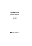
Power Requirements
The rear panel of the rrp 5+510Acontainsthe power input, voltage
selectormodule,power switc\ esernal @nnectors,and calibrator
protection switchesasshownin figure 2-1.
The HP 54510Arequiresa po\iler soruoeof either 115or 230Volts ag
- EVoto * 15Vo;singlephase,€ to 66 Hz;200 Watts maximumpower.
Power lnput
and
on/offswitchx$:ffijjJ"""tor
︱
︱
︱
︱
︱
︱
︱
︱
︱
︱
︱
︱
︱
︱
︱
︱
︱
︱
︱
︱
︱
︱
︱
︱
︱
︱
︱
︱
︱
︱
60 1111
lIIlllll・
DC Calibrator Output
ProbeCompensation
AC CalibratorOutput
CalibratiOn PrOtect Switch
Figure 2-1. HP 5451M Rear Panel
HP 54510A
Front‐Pane:Reference
:nstrument Setup
2‐
3
Selec'ting Une Voltage
The firsemodule is set at Hewlett-Packardto the linc voltageusedin the
eountryof destination. Checkthe settingof the fusemodule to veri$ it is
in the correct position for the voltageto be used. If the setti'g needsto be
changed usethe follovringprocedure.
CAUTION
BEFOREAPPLYINGPOWERTO 77IE INSTRUMENT,BE
SURE 7:HEFUSE MODULE IS SET TO T'HE CORRECT
LINE VOLTAGE POSWON. Sa,eretutnage will occurif the
Iine voltagek not popedy set.
Changethe fusemodule position by prrlling the fusemodule out and
reinsertingit with the appropriate arrows aligDed.
o
Careilly pry at the top center of the module asshownin figure 2-2,
until it can be graspedand pulled out.
Figurc2-2. SelectingLine Voltage
InstrumentSetup
2-4
HP 54510A
Front-Panel Reference
Verlfying the Fuse If it is neccssarytocheckor changefuses,removethe fusemodule and
look at eachfusefor its anperageand voltageratings.
︱
︱
劉
軒
Figure2-3. CheckingfortheComct Fuse
PowerCord The HP 54510Ais a SafetyClassI instrument with an ergosedchassis
that is directly connectedto earth via the power supplycord to meet IEC
Standard348. This instrumentis provided with a three-wire power cable.
When co'-ected to an appropriateac power outlet, this cablegrouadsthe
instruqrentcabinet.The rlpe of power cableplug shippeddependson the
country of destination. Seethe ncxt pagefor availablepower cords.
Line Switch
The line switch is located on the rear panel. Turn on the oscilloscopeby
pressing1 on the rocker switch. The rocker switch is labeled 1 and 0,
correspondingto on and off, respectively.
︱
︱
︲
︱
︱
。側
︱
・
llllllllIlll
llllllllllII
llllllIlllII lllI
Figure 24. Line Switch
HP 54510A
F『ont‐Pane:Reference
InstrumentSetup
2_5
…
PH臨
L―
…
"…
…
“
””
” “
:い0●●S193“
●ti●
”
“
mm嗜
lhtt.d lini6,
Cttrsa t
t i 9 . ?i r ,
zldtu.
slncrra
Gr.t
Iint
Gt.,
細 麺神
””“
4
″″2
Str●1■tt"● :C●['
” ””
: ■t ●C E E 7 V , 1
St7●
rint
Ilrl
h
Zaolond
Cr!t
Gr.t
Jo& Gaa,
8t.Gl
6no6o
intr..an.ct
ano
[email protected]
,r. iph.r! lr .
ond
hli.d
tt.t..
Conoao only
to.
.rrtfr
獅獅
””
∞∞
””
ワ υ
¨ ”
.F6rl hu6b.r .h-n
lor prug i. !.&.!.t
id..r;li.r
cdrr.t.
ccbr. 'ncrsd'6q prg9.
..1ha3r.ordi
or. iaclud.O in tir 6A cartificot;06
rn grouno
f{dr
16. prug 6^lt.
orororol
of
th.
Nd..
.hoi
lor
Gdbl.
i.
F
Dott.6.7
16'
aq{i@nt,
Figure 2-5. Available Power Cords
InstrumentSetup
2-6
HP 54510A
Front‐Panei Reference
:nten3町 COntrO:
Oncethe oscilloecopehasbeenturned on, the displayintensitycanbe
adjusted,if necassary.The intensityis adjustedwith the Display Intensity
control on the rear panel.
([:]) IIIIIIIIIII
IIIIIIIIIIII
IIIIIIlllllI
M・剛I
剛剛‖・
IIIIIIIIIIII
0
0
0
Figurc2-6. IntensityConnol
Air Flow
Requirements
HP 54510A
Panel Reference
Front‐
The HP 54510Amust haveunrestrictedair flow for the fan and ventilation
openingsin the rear panel. The HP 54510Amaybe stackedunder,over,
or betweenother instrumentsprovided the the other instrumentsare
adequatelycooled.
:nstrument Setup
2‐7
Connecting
External
Equipment
The HP 54510Ais equippedwith an HP-IB comector on tle rear panel.
This allons a direct connectionto an HP-IB compatible printer, plotter,
or externalcontroller.
Connectan HP-IB cableto the oscilloscopeand anyHP-IB compatiblc
device. Tightcn the HP-IB cablewith the captivescrewsof the cableto
avoid disconnectingthe cable.
O Π = = ビ Π= = u
0
lIIIIIIIl
([3) lII
n= = u
歴
曇
曇
3ρllll
IllllIIlξ
◎
◎
Figurc2-7. ConnectingExtanal Equipment
The HP 54510A must be properly addressedto communicate with the
connected device. The HP 54510A HP-IB address is set in the HP-IB
submenu. See "HP-[B Menu" in Chapter 12 for detailed information
about the HP-IB submenu.
lnstrumentSetup
2-8
HP 54510A
Front‐Panel Reference
Front-Panel
Overuiew
IntfOdUCtiOn tO
the FfOnt pangl
3
Thischapterdescribes
thefunctionalsectionsof theHP 545104front
panel.Theexplanationofeachareaalsocontainstheirinteractionwith
eachotherandprovidea basisfor applications
andusages.
into sixfunctionalareas.
Thefront panelis separated
。一
¨
¨
0一
0
¨一
¨
一
0
0
0000
0000
Entry Devices
Figure?1. HP 5451M Front Panel
ltP 54510A
Front-Panel Relerence
Front-PanelOverview
3-1
SystemControl
The SYSTEM CONTROL keysare located alongthe top of the
oscilloscopeto the right of the display. This sectioncontrolsthe following
functions:
o
o
o
Dynanicdsplayfeatures
Selectinglocalcontrol
Activating hardcopy
Selectionof anykey in the SYSTEM CONTROL sectioncausesthe
oscilloscopeto executethat comrnandimmediately.
00000
00 0 0 0 0
00000
0 0 0 Cl
① ① ⑮ 00
Figure3-2. SystemContol Section
RUN/STOPKey
Front-PanelOverview
+2
The RUN/STOPkeytogglesthe acquisitionstatusof the HP 54510A.If
the oscilloscopeis currently lunning (the current statusis displayedin the
the top left cornerof the displayin the message
field), the instru'nentis
placedin r&lestoppedmode. In this 6sds, normalacquisitionis stopped
and the last acquireddata is displayed. If the oscilloscopeis stopped,it is
immediatelychangedto anothermode(for exanple,running,awaitingor
uiger, auto-tngger).
HP 54510A
F『ont‐Panel Reference
S:NGLE Key
CLEAR D:SPLAY Key
The SINGLE keyactivatesthe acquistiongnstcnfor one trigger ercnt.
One acquisitonis madeand displayed;then the data acquisitionand
displaycycleis stopped. In repetitive mode,this singleacquistionis
superimposedon the current displayed&ta If the displayhasbeen
clearedbefore the SINGLE key is prxsed" only one acquisitionis
displayed.
The CLEAR DISPLAY key clearsthe displayand resets all associated
measurements.If the oscilloscopeis in the stoppedmode,all data that is
currently displayedis erased. If the oscilloscopeis running,all data is
erased;howcver,new data is displayedon the next acquisition. The
RUN/STOP and SINGLE keysare not affected.
The RUN/STOP, SINGLE, and CLEAR DISPI-AY keyshavea
relationshipthat makeit possible1q'nanipulatedata acquisitionsand view
one,two, or severalacquisitions. It is possibleto stop acquiring datq to
clear the displaS and to capture one acquisitionfor evaluation. The
displaycanbe clearedwbile acquiring to capturenew data. The
acquisitionscanbe manipulatedwith thesethree keysand other keysand
settingsare not affected.
LOCAL Key
The LOCAL key sendsa return to local control messageto the IIP-IB
interface and returns control to the front panel.This key can be locked
out if a local lockout comrnandis executedover the HP-IB.
This is the only activefront-panel keywhile the oscilloscopeis in remote
operation,ifit hasnot beenlockedout.
HARDCOPY Key
The HARDCOPY key executesan inmediate hardcopyof the currently
displayeddata on a compatibleplotter or graphicsprinter and stopsall
other oscilloscopefunctionswhile printing.
The oscilloscopemust be in the talk only mode,and the hardcopydevice
must be in the listen alwaysmode. Setupof the hardcopyoptions is
in the HP-IB submenu(seeChapter12,"Utilities Menun).
accessed
Selectionof anykeyabortsthe hardcopyaction.
HP 54510A
Front‐
Pane:Reference
Front-PanelOveMew
3-3
Setup
for displalng
The SETUP sectionof the front panel controls subsystems
input data- The setupsectioncontrols the following displayinfornation:
o
o
o
AUTOSCALE for automaticscalingof the waveformdisplayarea
SAVEandRECAllsetups
Quick aeoessts sfuannelfunction, and trigger information on the
SHOW screen
000 0000
00000『
0
ooooolll
oooqfll
o
o
回 回 ロ ロ
Figure?3. Seup Section
Front-PanelOverview
&4
HP 545104
Front-Panel Reference
AUTOSGALE Key
This key causesthe oscilloscopcto evaluateall input signrlqand set the
correct conditionsto displaythe signals.When AUTOSCALE is pressed
the following conditionsare set:
● ● ●
Vertical sensitivityon all channels(if applicablQ
Vertical offset on all channels(if applicable)
Trigger edgemode,positiveslope,and proper trigger level for the
trigger souroe
Setsto minimum perisitencewhen in normal displayand repetitive
acquisitionmodes(singlepersistencein real time acquisitionnode)
Time per division
Autoscale also includesa soft resetwhich performsthe following:
o
o
o
o
o
o
o
o
Turns offAVAV markers
Turns offall measurements
Turns offmeasurenent limit test
Turnsoffwaveformmathfunctions
Turns offwaveform/pixelmemorydisplay
Turns off statistics
Turns offconnect-the-dots
Setsholdoffto zl0ns (minimum vralue)
The previousoscilloscopesetting are storedin volatile memory
RECALL 0. To recall setting, pressRECALL 0.
RECALL Key
The RECALL key hasthree primary functions:
Pressingthe RECALL keyand thenselectingL,2,3, or 4, causes
recall of a previouslysavedsetupconfiguration.
The current configurationis automaticallysavedbefore executionof
an autoscale,recalt or settingup ECIJTTL presets. RECALL 0 is
an undo of theseactions. Waveformscannotbe savedto RECALL 0.
PressingRECALL CLEAR resetsthe instrumentand returns the HP
545104 to defaulVpower-upsettings. The oscilloscopedoesnot
perform power-upself-tests(seeInstnment Reset).
HP 54510A
Front-Panel Relerence
Front-PanelOverview
3-5
SAVE Key
SIIOW Key
The SAVE key immediatelystoresthe oscilloacopesetupconfigurationin
nonvolatilememory. PressSAVE, and then seled a saveregister:1, 2, 3,
or 4. An advisoryis displayedabovethe waveformdisplayareaindicating
tle setupconfigurationhasbeensaved.
The SHOW key accessesthe following information:
o
o
o
o
o
o
o
o
o
o
o
Channelscaling
Channeloffset
Channelcoupling
50Q
Probeattenuation
Trigger sour@
Trigger level
Math functioo operation
Math function scaling
Math function offset
Memories
Pressi'g the SHOW key togglesbetweenthe currently selectedmenuand
the SHOW screen.
This screenpresentsthe most completeand detailed instrumentsetup
information. Sslssl this screenbefore making a hardcopyto include all
SHOW screeninformation on the hardcopy.
Fronl-PanelOverview
3-6
HP 54510A
Front-Panel Relerence
Menus
The MENUS scctionconsistsof nine kep:
TIMEBASE
CHAN―
TRIG
DISPLAY
At/AV
WFORM MATH
WFORM SAVE
MEAS
DE―
■「H L
Each of thesemenusis discussedin the following chapters.
00000
0000
目
昌6
言1目
目
囲
口
0口
④
Figure34. MenusSection
HP 54510A
F『ont‐Panel Reference
Front-PanelOverview
*7
丁
Entry
―
―
―
―
―
―
―
― ―
The ENTRY devicesectionspafeinsa multifunction nu-eric kelpad, a
selectionknob, and a FINE key.
8日
0- ―
0000
固
ロ
目
目○
目
目
ENTRY
Figure 3-5. Entry Section
Numeric Keypad
The keypadis for direct numericinput. To input knownvaluesdirectly,
pressthe associated
softkeyto activatethe desiredfield on screen,and
then selectthe units with the numeric keys.For example,do the following
stepsto set the vertical sensitivityto 500mV:
SelectV/div in the Channelmenuto ensureit is the activefield
(displayedin tu[brigb$
Press5,0,0, mV in sequence.
Front-PanelOverview
3-8
HP 54510A
Front‐Panei Reference
The blue key on the numeric kelpad selectsthe alternatefirnction cfien
pressedbefore a nuneric key on the front-panel keypad. The alternate
function of the kep on the rigbt column are measurementunits. The
CLEAR key clearsany selectionsmadefor the activefield.
Knob
FINE Key
The knob changesvalueswithin eachfunction. It increments,de6ements,
or togglesthe selectionin the activefield or function. The current
selectionis displayedin fullbright in the displayedmenuarea and canbe
changedwith the knob.
The FINE key changesthe incrementand decrementsequence.Instead
of sequencingin the normal sequence,the valuesincremenVdecrementin
more precisevalues. Use this feature when the normal sequenceis too
coarsefor precision measurementsor settings.
When the HP 54510Ais operatingin the fine mode,the word.Jineis
displayedin the lower right corner of the CRT.
InpUt
HP 54510A
Front-Panel Reference
The input sectionconsistsof connectorsfor sipal input. Channelinputs1
and 2 select1 MQ or 50 Q input inpedancesand eachis shuntedby
approximately7 pF at the input BNC with a maxim'm input voltageof
250V ( > 50 mV/div range). SeeAppendixB, "GeneralInformation"for
specificationson the input channels.
Front-PanelOveruiew
3-9
TimebaseMenu
introduction to
the Ti『
nebase
TIMEBASE
This chapterspa[einsa description of the TIMEBASE menuand how the
entire horizontal displayand parametersare controlled with this menu.
TIMEDASE
TIME
D:V
oaroy
reference
睦負
市¨ t
国
t a faa anca
cttl ccnt..l .i0ht
■ off■
on
│
! rGbosc
rcactitivr
rcoltirc
poa i t ion
54502W22
Figure41. TimebaseMenu
Time/Div Key
The time/division function controls the time scale on the horizontal axis
from 1 ns/div to 5 sec/div. The main timebase is incremented and
decremented n a L-2-5 sequence. The FINE key does not affect the
timebase settings while the acquisition is lrrnning.
This key affects the sample rate at which the scope aquires data. The
sample rate for the selected time/div setting is displayed below the
time/div freld. In the realtime mode and with the acquisition stopped, this
key also controls the zoom feature (see repetitive/realtime key in this
chapter).
HP 54510A
Front‐Pane:Reference
Timebase
4 卜1
Acquisitions are not displayeduntil all data is arailable (sinilar to normal
acquisitons)to display. As data is being sanpld the advisory n s to
initistized is displayedwhile pre-trigger data is.collectedand n s to
completeis displayedwhile post-trigger data is collected. This message
indicatesthe time neededto completeacquisitionwhere n is the
lsneining time (in seconds,s) and continuesto countdoumuntil the time
haselapsed. The advisorymnning is displayedasthe write cycleto the
screenii executedand displayeddata is updated.
The total tir"e acquired and the samplerate are dependenton the
timebases,stting.Listed below are the total acquisitiontimesand the
samplerate for eachtimebassssltingin real ti-e mode.
TIIMEBASE
ns■
…
SAMPLE RA‐
time
1
500 MSals
10 us/d市
16 uscc
32 uscc
80 uscc
160uscc
3Z) uscc
8{X)uscc
1.6mscc
2Cl us/d市
3]@
25 MSa/s
50“ /d市
8 rtracc
16 nscc
32 mscc
80 mscc
160mscc
320msec
800mscc
1.6scc
3.2scc
8 scc
16scc
32 scc
80 scc
160scc
320scc
800sec
lCXl ns/d市
200 ns/d市
500 ns/d市
l us/d市
2熱 も市
5 us/d市
100 us/d市
2Ю uS/d市
500 us/div
lm/d市
2 ms/d市 ,
5 ms/div
103/d市
20 ms/d市
50 ms/d市
1∞ ms/d市
200111s/div
SCЮ ms/d市
ls/d市
2s/d市
5s/d市
Timebase
4‐2
此 TIME
Tσ r′
A∞ UIRED
250 MSa/s
lCXI MSals
50 Mb/s
25 MSa/s
10 MSa/s
5 MSa/s
l MSa/s
500 kSa/s
250 kSa/s
100懸h/s
50 kSa/s
25 kSa/s
10 kSa/s
S kSa/s
25 kSa/s
l k Sa/s
500 Sa/s
250 Sa/s
l∞ Sa/s
50 Sa/s
25 Saお
10 Sa/S
HP 54510A
Front‐Panel Reference
delayKey
Selectingielay assignsdelayastle activefunction. When delayis set to 0
the trigger eventoccursat the delayreferencepoint. Positivedelay
indicatestime after trigger and negativedelayindicatestime before
trigger. Tberefore, a delay settingof -50 ns indicatesthat the trigger event
occurs50 ns after the delayreferencepoint. In the real-time mode and
with the acquisiitonstopped,delaycontrols the pan feature (seethe pan
and zoom exercisein this chapter.)
refer.encc= trigger event * delay
referenceKey
The rcferencekey changesthe delayreferencepoint to one ofthree
referencepoints:
o
o
o
left
cntr (center)
right
If delayis setto 0, the referencepoint consistsof pre-triggerdatato the
left and post-triggerdatato the right.
NOTE
Thetimefrom triger changeswith the delayseningand is
displqed at the bottomof the waveformareoat the left, center,
and ight of the display.
HP 54510A
Front-Panel Relerence
Timebase
+3
repetitive/
realtimeKey
The bottom function key selectsone of the trnoacquisitionmodesusedby
the HP 54510A:
o
o
repetitiveacquisition
realtine acquisition
SeeChapter7, "DisplayMenu" for more on acquisitionmodes.
repetitive mode
The repetitivemodesetsthe HP 54510Ato acquiredatain the repetitive
acquisitionmode (seeFeelingComfonablelilith DtgttizmgOscilloscopes).
la this 66d6, the oscilloscopesamplesdata continuouslyand builds up a
repetitivewaveformafter manydata points havebeen attained;this mode
is usefulwhenviewinga continuouswaveform.
In the repetitivemode:
realtime mode
o
The HP 54510Adisplaysdatacollectedfrom multiple acquisitions
from eitheror both channelinputs.
'
adisprav
:,?"fiHT
tr"';;;;:::t::A;:*"
il:"#ilr*:'3fi
o
Data from eachacquisitioncanbe displayedfor a definableperiod of
time (persistence).
.
Waveformrecordsare establishedat 501datapointson all
time/divisionssrings.
Whenin realtimemodethe HP 54510Adisplaysdatacollectedduring
successive
5ingls-5[e1acquisitionsfrom eitheror both input channels.
The HP 54510Acanmakea single-shotcapturesimultaneously
on both
channels.
Two simultaneous,
non-recurring,or verylow repetitionrate eventscanbe
capturedat the sametime.
Timebase
+4
HP 54510A
Front-Panel Reference
Someor all of the 8k waveformbuffer memories(eachchannelhasits om
8k buffer) canbe displayed. The displayedsigal is completelyupdated
aseachacqnisitionis made.
The following graphicsare shownat the top of the displayarea and in
figure 4-2:
memorybar - representsthe displayedportion of the waveformrecord
memorybar displayline - representsthe entire 8k waveformrecord
'I - indicatesthe trigger point's location within the 8k waveform
record.
MEMORY BAR DISPLAY LINE SHOWS
WAVEFORM RECORD
T SHOWS
TRICC[R
MEMORY BAR SHOWS
PORT10N OF WAVEFORM
RECORD THAT IS BEING
DISPLAYED
MemoryBar
Exercise
the real time acquisitionmodememorybar
This exercisedemonstrates
and the abilityto displaysignalsthat occurbeforeand after the trigger
eventof the displayedsignal.The memorybar showsthe portion of the
waveformrecordthat is beingdisplayed.
o
HP 54510A
Front‐
Pane:Reference
Connectthe HP 545104rear-panelAC CALIBRATOR signalto
channel1 with a coaxialcable.
Tirnebase
■5
Disconnectanyother signalsthat maybe connectedto otler inputs.
PressAUTOSCALE and then stop the acquisitionwith the
RUN/STOP lcey.
Selectdelayin the TIMEBASE menu.
Use the entry devicesto vary the delay. The memorybar at the top of
the displaymoveswith the delay referencesfuanges.The memorybar
is shoⅧ ln flgures 3,4-4,and
4‐
5.
4‐
■
3tOppeC
…
鵠
left E
-5 00000 ● 3
0 00000
S
rlght
5 00000 ● s
43. MemoryBar at Centerof Acquisition
Three different portions of the waveforrncanbe viewedwhile the
acquisitionis runningasshownin figures+2, +3, and44. Either left,
ceoter,or right canbe selectedwith the delayreferencekeyin the
TIMEBASEmenu.
When the acquisitionis stopped,the the displaycanbe placedat any
portion of the waveformrecordby changrngthe delayvaluein the
TIMEBASE menu.
The delayvaluemovesthe 8k acquisitiondisplayrelativeto the trigger
point.
Timebase
4‐6
HP 54510A
Front…
Panei Reference
rattranca
lo「
tcntr m
・
―:00∞
0● 3
-5000∞
●3
45. MemoryBar at Rightof Acquisition
As the delayvalueis changed,the'P movesto the right or to the left
alongthe memorybar dependingon a positiveor negativedelayvalue.
Negativedelayvaluesshowpre-trigger eventsand positive delayvalues
showpost-triggereventsin the acquisitiondisplay.
1由
er司
ビ器
…
….:‥
…… ■
二……
│
│
!0 0000 ● s
44. MernoryBarat Left of Acquisition
HP 54510A
Front‐Panel Reference
Tirnebase
4‐7
Single-shot
Exercise
This exerciseshowsthe single-shotcapabilitiesof the HP 54510A.
$ingile-shot,in repetitive displaymode,is usedto build a waveformwhile
displayingthe l gigasample/second
r4e. gingle-shot,in real-timemode,is
usedto compareinterpolated with non-interpolateddata.
The 1 gigasample/second
digitizing rate of the HP 54510Aallowscapture
ofvery fast non-recurring events,suchas a microprocessorstart-up
sequence.Error causingglitchesthat disrupt systemperformancecanbe
capturedfor analysis.
Single-shotin Single-shotis usedto build a waveformwhile displayingthe L
RepetitiveMode gigasample/second
sampleand digitize rate.
r
Connectthe HP 54510Arear-panelAC CALIBRATOR sipal to
sfiannsll with a coaxialcable.
Disconnectanyother signalsthat nay be connectedto otherinputs.
PTessAUTOSCALE.
In the TIMBASE menu,changetimebaseto l0 ns.
Setthe acquisitionmodeto repetitive.
Pressthe STOP/RUN keyto stopacquisition.
PressCLEAR to clear the display.
Pressthe SINGLE and CLEAR keysalternatelyto displayand erase
single-shotdata.
Pressthe SINGLE keyrepeatedly.The waveformfills in with each
single-shotadditionto the waveform,asin frgure4-6.
Timebase
+8
HP 545104
Front-Panel Belerence
一
-50.OOO n3
.nrg I
46. Single-shotWaveform
Built-up in RepetitiveMode
When averagingis off:
r
o
datapointson the displayarenot gfuengedbynewdatawhen
the
SINGLE keyis pressed.
datastayson screenuntil the instrurrentsetupis modifiedor CLEAR
is pressed.
When averagingis on:
o
o
dataon screenis averagedwith newdataeachtime SINGLE is
pressed.
it is assumedenoughdatapointshavebeenacquiredto satisfythe
nu-ber of averages
setin the DISPLAY menu.
To viewthe L gigasample/second
digitizingrate:
o
PressCLEAR.
o
PressSINGLE.
The displayshowsa seriesof points1 ns apart asin frgurezt-7.This 1 ns
separationis definedby the l gigasample/second
digitizingrate.
ヽ
HP 54510A
Front‐Panel Reterence
Timebase
4‐9
一
│
:
…
│
。●V I
I■
■
10。
4Lz′ Gい
:
・6 ′
1lV
切
IcISCC“′1)lg"taル
lgRarθ
shot h the repetttacquisition mOdc
To observe the limitations of single―
o Sclcctthe TIMEBASE menu and set timebaseto l ns.
● Press CLEAR and then SINGLE.Ten data points from the input
slgnd arc displayed as m flFe 4-8.
わ
●1 0 p p e d
dalcg
Irft E
48.
Timebase
/l.10
rrrhl
Ten-point ll/avefonn in Repetitive Mode
HP 54510A
Front-PanelReference
Sing:e‐shotln Rea:
Time Mode
In the real time acquisitionnodg the data is interpolated at faster
timebasesettingsfor a more usefirldisptay. To observethe difference
betweennon-interpolatedand interpolated data:
o
Selectrealtime in the DISPI"AYmenu.
Pressthe CLEAR key.
Pressthe SINGLE key. The waveformis displayedasin figure,$-9.
b
,lopp.d
?:iE!ASE
鵠
l
一H‐……+■“
コ
+9. Ten-pointWaveformin Real TimeMode
In the real time acquisitionmode,the HP 5451.0A
usesa digitd
,overga:uplbg;-filterto provide a more continuouswaveformdisplay. It
/automaticallyoperateswhenthereare lessthan501pointson the display.
I
4tw 74rrC
HP 54510A
Pane:Reference
Front‐
Timebase
+11
Pan and Zoom
Pan and zoomfeaturesare availablein the real time acquisitionmode and
operableonly when the acquisitionis stopped. Applications that require
preciseevaluationof low repetition rate signals,suchasradar and
transponderpulsetreins, are simplified by zoomingand pan"ing on
single-shotdata.
Zooming either expandsor compressesthe acquiredwaveformon the
horizontal axisof the display. It is controlled by the timebasetime/div
control for expansiogmagnification,or sompressionof a singls-5he1
waveformin the real time acquisitionmode. Decreasing tims/div
expandsthe waveformand is referred to asnzoomingin". lncreasing
time/div compressesthe waveformand is referred to asn2s6mingout".
Panningis movingthe acquired waveformhorizontally on the display. It
is controlledby the timebasedelaycontrol. Increasingthe delaymoves
the waveformto the left and increasi'g the delaymovesthe waveformto
the right.
Pan and Zoom
Exercise
Thiq exerciseshows how the timebase is used to zoom in on and zoom out
ef 3 singls-5fuotwaveform. The delay timebase is then used to pan the
waveform horizontally on the display.
Usinga coaxialcable,connectthe rear-panelAC CALIBRATOR
signalof the HP 545104to channel1.
PressAUTOSCALE. The rear-panelsignalis displayedon screenas
in frgure4-10.
Timebase
+12
HP 545104
Froril-Panel Relerence
+
slopped
1
200 oV′`iv
Off30t:-4:2.5 ● V
:.000::
dc
-5 00000 ●
s
0,00000 s
i.00 ●s′1lv
5.00000 ● s
1
」
-204.5 oV
4 10.Rear-PanelSignalAutoscaled
Zooming In TIMEBASE menu, select rcaltimeacquisitionmode.
PressRUN/STOPkeyto stopthe acquisition.
PressCLEAR keyto clearthe screen.
Pressthe SINGLE keyto acquireone dataacquisition.
Selecttime/divisionin the TIMEBASE menu.
Rotatethe front-panelknob. Increasingtime/divdisplaysmore of the
acquiredwaveformon the screen.Decreasingtime/div zoomsin on
the acquiredwaveform.
Settimebaseto 20 ms/div. The entireacquiredwaveformis displayed
asin figure 477. The memorybar alsoshowsthat the entirememory
is on the screen.
HP 54510A
Front‐Panel Reference
Timebase
+13
4r
h.rdcopu ln trogrlrr
l.00 ●6′│:"
鵠
rer●r●nc●
1∞ ∞003
20.0● 6′diV
411. Zoorning Out of theAcquisition
Set timebaseto 20 us/div to zoom in on the acquisitionasin figure
4-12.
ケ
…
饉
.出
er司
:∞ 000 ● 3
412. Zoomingln on theAcquisition
The HP 545104 usesa digital oversampling filter to hll in the waveform
for a more usable display at this sampling rate. The memory bar indicates
the portion of the acquisition that is displayed.
Timebase
+14
HP 54510A
F『ont‐Panel Reference
Panningmovesthe acquisitionleft and nght for analyzationof waveforms.
o
Selectdelayin theTIMEBASEmenu
o
Use the front-panel knob to increaseand decreasedelay.
As delayis increased the acquisiitonpansto the left becausethe window
is pastthe trigger point, asin frgure41i1.
50.O u● ′│:v
4 ′ユ R α″: 4′g ゎ Й` ιψ
HP 54510A
Front‐Panei Reference
Timebase
4‐
15
When the delayis deseased the waveformpensto the right asin figure
zl-14.The databefore the trigger point is being displayed.
4p
nardcoPg In pro9rE36
-
l oo-/6rrJ
iL
i_ !.i!s _)
i
i
│
:+t
: 1 趣
'----'ieFro..l
i
:
Hetter司
--_------
4 f 4 2 α “″′
t g め働` R 妙 ′
T h c m c m o r y b a r m O v e s t o t hocr lrei■
ght as the acquisition is panned.
Panning and z00mmg can bc uscd concurrcntlyto cxammc the
acqlllCition.
Zoom out of the acquisitionby increasingthe timebase.
Selectdelayand usethe knob to centerthe acquisitionareaof
interest.
o
Timebase
It-l6
Znom back in on the waveform of interest.
HP 54510A
F『ont‐Panel Reference
ChannelMenu
Introductionto
Channels
5
The channelmenu is a two-levelmenu and controlsthe vertical operation
of the HP 54510A. This chapter decribesthe useof the nvo input
channels,losluding vertical sensitivity,offset, coupling,attenuationand
presetlevels.
CHANI€L I,z,EXI
Figure5.1. HP 5451MChannelMenu
HP 54510A
Front-Panel Relerence
ChannelMenu
5-1
CHANNELKey
The top key in the channelmenu is for channelselection. This key
togglesbetweenchannelsL, \ andetrernal. When a channelis selected
(highlightgd in inversevideo) it can then be turned on. When a channelis
turned on the small circle imnediatelv below the channelnumberis
highlighrcd.
Note
h ispossibleto havea channeltumed on and viewwhilebeingin
the verticalcontrolmenuof anotherchannel. lVhenmaking
changes,enEure
you havetheproper channelandfunction
selectedandyou arechangingthe channelyou intendto change.
Vertlca:
SensitivityKey
The vertical sensitivitykey is the third key from the top in the channel
menu. The field itself is not labeled,holever, the current volts/divisionis
displayedwith the units of the current selection. When this function is
selected,either ofthe entry devicescanbe usedfor dataentry.
The rangeof the vertical sensitivityfor the HP 54510Aisfrom
1 mV/division to 5 V/division. Vertical sensitivitychangesin a L-2-5
sequencewith the knob. When the front-panelFINE keyis selected,fully
calibratedvernier adjustmentscan alsobe madeusingdirect keypadentry
or the knob.
offset Key
When offset is selected,the trace can be moved up or down with the knob
or the keypad. Offset moves the voltage level at mid-screen.
Offset moves the displayed signal up or down, similar to the vertical
position adjustment on an analog oscilloscope. However, becausethis
oscilloscope has a true dc offset at the front end, it provides a much wider
offset range. The offset voltage (referenced to the vertical midpoint of the
ChannelMenu
*2
HP 545tOA
Front-Panel Reference
waveformdisplay)is shovmat the right of the waveformdisplaywhenthe
SHOW keyis pressed.
CouplingKey
The couplingkey hasseveralselectionvariables:
odc
o dcBWlim
oaC
.
r
acBWlim
acLFreject
When dc is selected,1 MQ and 50Qdc input inpedancesare availableas
choicesfor input impedance.
Bandwidth limit is switchablewith the different combinationsof the
coupling function. Bandwidth limit reducesthe effectivedc bandwidthto
about 30 MHz. Ac coupling providesx high-passfilter that rejects
frequenciesbelow about X) H;z.The LF reject providess high-passfilter
rejectingfrequenciesbelowabout 4frH2. Bandwidthlirnils xad LF reject
filters reducethe noisein the vertical path and the trigger path.
Input
lmpedance
HP 54510A
Front-Panel Reference
Input impedanceis 1 MSI for ac couplingand selectable1 MQ or 50 Q dc
when dc coupling is selectedin the couplingfunction.
ChannelMenu
$3
The more keytogglesbeh*'eenthe two levelsof the channelmenu.
probe key
The probekey selectsprobeattenuationwith a rangeof 1000:1to .9000:L.
Attenuation is adjustedby either knob or entry keypad. When the knob is
in coarsemode,adjustments
are incrementedor decrementedin the 1-2-5
sequence.When in fine modeadjustmentsare in 0.1increments.
Probe attenuationaffectsscalingfactorsfor the display,not sensitivityat
the input.
Probeattenuationis calibratedin the Utility menu. SeeChapterL2,
"Utility Menu",for informationon probe calibraation.
Attenuationfactorsare savedwith the front panelsetup.
Channei Menu
5‐4
HP 54510A
Front‐Pane:Reference
EGLKey
The ECL key setsthe oscilloscopcto levelsoptimizedfor ECL circuia:
.
o
o
o
o
.
V/Diu 200mV/div(400mV/divif # of screensis2)
offsec -1.3 V
coupling: dc
Trigger levet -13 V
Triggerslopcnochange
RECALL 0 returns the.menuto the previoussettings.
TTL Key
The TTL key setsthe oscilloscopeto levelsoptimized for TTL circuits:
o
o
o
o
o
V/Diu 1 V/div (2Y ldivtf # of screensis 2)
offseh25V
coupling:dc
Tt'tggerlevet 1.4V
Triggerslope:nochange
To return to the previoussetti4gspressRECALL 0.
HP 545r0A
Front-PanelRelerence
ChannelMenu
$5
TriggerMenu
6
range■
om simple
岬価“
the THggers 雛路路軋此詣寵
踏
」t i p l e 鋤
山 .
This chapter cOntalns descriptions ofthe tFigeFing mOdesp and
"lanadOns on hov7to use themP and exercises detailing sOme real鵬
叩pEcations.The HP 54510A h8 Flvetriggett modes:
● Edge
● Patten
● State
e Delay
O
Tfiggef
MOde
lntgfaCtiOn
TV
The triggerlevel(threshold)for eachchannelis set in the edgetrigger
menuand is independentfor eachcftennsl.It is carriedover to all other
modes,exceptthe TV trigger mode. Theselevelsare important settings
becausefts high and low levelsin the pattern, state,and delaymodesare
defined asbeinggreater than or lessthan the trigger level.
The level for TV trigger mode is a specialcaseand is set in the TV trigger
menu.
HP 54510A
Front‐Pane:Reference
Trigger Menu
G 卜1
EdgeTrigger
The edgetrigger mode hasthe following selections:
Mode
r
o
r
o
o
o
Trigid/auto
Trigger sour@
Triggerleveladjust
Slope
Noise reject
Holdoff
trig'd/outo
source 1,2,EXT
noise reject
Figure61. EdgeTiger Menu
TriggerMenu
a2
HP 54510A
Front-Panel Reference
trlgU/auto Key
The trig'd/auto selectiontoggl€sbetcrcenthe two triggcr modcs. The
cturent selectionis displayedin inversevidco. This field is arnilable in all
trigger menus.
In the trig'd mode,the oscilloscopedoesnot display data until all of the
trigger requirementsare satisfied. While waiting for the trigger
requirements,the messagean'aitingnigr is displayed. In the auto mode,
if a trigger is not found" a trigger is generatedand acquired data is
displayed. A statusmessageis displayedin the upper left corner of the
scroen.
source Key
level Key
The sourte key selectsthe trigger souroe. The options are channels1 or 2,
or externaluiger. The current selectionis highlightsd in inversevideo.
The level key setsthe trigger level. The rangeon this function is + 12
divisionsfrom center. It providesflexibility for seningexacttriggering
points and specifieslevelsusedin the more sophisticatedtriggering
modes.The center can alsobe selectedwith centered.
slope Key
This field is not labeled,however,the availableselections are graphic
representationsof the rising edgeand falling edge The current selection
i5 highlighrcdin inversevideo.
noise reiect Key
Turn noisereject on for triggering on noisy.signalswithout the problem of
falsetriggering.
holdoff Key
Pressingthe holdoff key assignsthe entrydevicesto controlholdoff.
Holdoffdisables the trigger circuit for a selectabletime period or number
of eventsafter the triggerevent. Holdoffis selectedin 20 ns time
increments,from 40 ns to 320 ms or in number of eventsfrom 2 to
15000000. Time and event are toggledwith the knob. Eventsare
numberof patterns(patrn), state(state),or edgeand w (edge).
HP 545104
Front-Panel Reference
TriggerMenu
s3
EdgeTrigger
tWith HOldOffl
Exercise
This exercisesetsup the oscilloscopeand a signalgeneratorto view some
of the featuresof the edgetriger. Holdoff is usedto gain a stabletrigger.
This techniqueis not necessaryfor most applicationsand waveformg
however,for manynon-recurring and irregular waveformsit is useful.
lnstrumentSetup Follow the instructionsfor seuiqgup the sig[al generator. The signalfor
this exerciseis a burst pattern with two positivecyclesthat repeatsevery
5ps. Use an HP 8116APulse/FunctionGeneratorwith the burst option
or a signalgeneratorcapableof the samesiglal.
Make the following setting:
o
o
o
o
o
o
o
o
Trigger Menu
●4
MODE: I.BUR
RPT: 5.00ps
BUR:2
FRQ: lMHz
D"f\[: fiVo
AMP: 1V
OFS: -200mV
Set the sigpalfor a squarewave.
HP 54510A
Front‐Panel Reference
Oscllloscope Setup
Connectthe the signd generatorto the chrnncl l input and disconnectall
other inputs.
o
PressATITOSCALE (seeFigure 62).
tp
runnIn9
1 500 mV/div
offset:-375 0 mV
1 000: l
dc
0
1 00 us/div
rco I i. imc
-ss.o-v
1f
s45o4ro3
FigureG2, Two-Bunt wareform ofterAutoscale
o
Selectthe TIMEBASE MENU.
o
Set the sweepspeedto 5fi) ns/div.
o
Set acquisitionmodeto rtpetitive.
The HP 545104setsup the displaypar'.meters.It is now attempringto
trigger on the first rising edgeof the rwo cycleburst.
o
Enter the TRIGGERMENU and pressthe slopekey.
The oscilloscopeis now attemptingto trigger on the first falling edgeof
the two-cycleburst. Pressthe slopekey egainto triggeron the positive
edge.
HP 54510A
Front‐Panel Reference
Trigger Menu
←5
Nde
Tte signatgenerunris setfor two 500ns pulses.Thedisployon
the oscillosape qpe&t to harrethreeprulses.This is on
unstobleuiger condition. Thefolla+ing stqs qlain this
condition ondhow to overconeiL
fip stoppld
` 3 7 w a ‐b “が 動 膨
Determiningholdofitime. Changethe time/divsettingto2 psldiv.
PressRUN/STOP (STOP),CLEAR DISPLAY, and SINGLE. This
showsthe period of the waveform. Sincethe oscilloscopeis
recogpizingnvo valid trigger events(edges,in this case)of the burst,
1[s fusld6fftime needsto be setsuchthat it ignoresthe secondpulse
in the burst. Using A t markers, the secondedgecanbe found to be
about1ps from the fust edge.(SeeChapter8, "Deltat/Delta V
Menu.")
Pressthe holdoff key.
Setholdoff to 1.04fi)0ps,with keypador knob.
TriggerMenu
s6
HP 54510A
Front-Panel Reference
hp runn ing
-?.
rePet
I t i ve
Figure64. Two-BuntPulsewlStableTiger
The input signalto the oscilloscopehastwo 500ns pulses. On the lirst
risrng edgea trigger occursand activatesthe holdofftimer. When the
holdofftine (1.0a000ps)haselapsed,the oscilloscope
lools for another
trigger. The oscilloscopetriggerson the frst rising edgeof the second
burst. Each tiger eventoccurson a different pulse,and is consequently
al unstablecondition.
By adjustingholdoffto wait until the risingedgeof the secondpulse
passes,the oscilloscopetriggersonly on the fust rising edgeand the signal
is stable. In this casethe trigger is stablewith approximately
t.Mps holdoff.
HP 54510A
Front-PanelRelerence
TriggerMenu
67
Pattern Trigger
Mode
The pattern mode definesa lbit pattern for the oscilloscopeto recqgnize
and generatea trigger event. When the inputs satisfythe trigger pattcrn
and conditions,the HP 54510Atriggersand displaysthe desiredportion
of tle waveform.
The pattern modeis rary useful for glitch detectionbecausethe
HP 545104triggerson a glitch and displaysthe resultingwaveform.
lr i9'd,/oulo
pr esent>
holdoff
time 40ns-320ms
events 2-16 000.000
Fignre65. PanemTiger Menu
pattern Key
Trigger Menu
e8
This is an unlabelledfield. The displaydepictsthe 3-bit pattern. The
activefield is displayedin full-brightand is changedwith the knob. The
functionkeycha'gesthe bit selectionof threelevels:
HP 54510A
F『ont‐Panel Reference
panern Key Thisis anrmlabelled
field" Thedisplaydepicts
theSbit pattern The
activefield is displayedin fu[-bright -6 is changed
with theknob.Tbe
functionkeychanges
thebit selectionof threelcvels:
1
o
o
ll _ high
L-low
X-don'tcare
The criteria fsl high is highgl than 1f,9current trigger level and low is
lower then the current trigger level.
The 3-bit pattern representsthe two channelinputs and the e$ernal
trigger. The left-most bit correspondsto channel? andthe right-mostbit
correspondsto the erernal trigger chqnnsl.
For exanple, if the pattern is LXH, the voltageon channell must be
lower than the trigger level set for channel1, channel 2 is don,t care so
1[s input level is disregarded and the externaltrigger input mustbe
highsl than the triger level set for externaltrigger. If theseconditions
are satisfiedby the inputs, then the oscilloscopegeneratesa trigger event.
Note
llhen any channelis not beingusedin the qualifierpanem"it
shouldbesetas don't care. Thetriger levelis still comparedto
the no input channeland a higlt or low is determined.Theonly
truedon't careis X.
If the patternXXX is selected,a triggereventdoesnot occurbecausea
triggereventis not defined.
when Key
This keycontrolsfive setsof conditionsthat mustbe satisfiedto generate
2 6igger event.Theseconditionsare asfollows:
o
HP 54510A
Front-Panel Reference
when entered: a trigger is generated on the hrst transition that makes
a pattern true. The pattsrn must be false and go true to generate the
trigger.
Trigger Menu
&9
when exite& a trigger is generatedon the first transition that makes
the pattera false. The pattern mustbe true and go falseto generatea
trigger.
r&en prcsent > : a trigger is generatedwhen a trigger pattern is true
longer than a specifigdminirnurntine period. This time period is
specifiedin the next selectionkey that is activatedwhen present > is
selected. The present > time rangesfrom 20 ns to 160ms
rvhenprcsent ( : a trigger is generatedwhena trigger pattern is true
lessthan a specifiedmaximu'ntime period. This time period is
specifiedin the ne:dselectionkey that is activatedwhenprrsent < is
selected. The prcsent ( tims rangesfrom 20 ns to 160ms.
.
holdoff Key
PatternTrigger
Exercise
range:this trigger condition is a combinationof prcsent < and
present >. A trigger is generatedwhen a trigger pattern is true for
longer than a specifisdrninirnumand shorter than a specified
maximumtirne period. Thesetime periods are specifiedin the next
two selectionkeysthat are activatedwhenrange is selected. The frst
range time settingmust be lessthan the second1""ge time setting.
The holdoffkey assignsthe entry devicesto controlholdoff. Holdoff
disablesthe trigger circuit for a selectabletime period or number of
eventsafter the triggerevent. Holdoff is selectedin time urits, from 40 ns
to 320 ms and is incrementedin 20 ns intervalsor by number of patrn
(patterns)from 2 to 16000000.
This exercisedemonstrates
how to definethe 3-bit patternand how it
affectsthe trigger and the resulting display.
Note
Setthe triger levelfor eachtriger sourcewhilein the edgemode.
Thesetiger levelsmust besetbeforeyou go to thepattem mode,
or propertigeing may nol occur.
TriggerMenu
sl0
HP 54510A
Front-Panel Reference
lffitrumenl Setup
To perform the following crerciseusethe HP 8116APulse/Frmction
Generator,or another frmction generatorcapableof produciagthe sane
1 MHz, 1volt" squareq,aYssigrral.
Set up the HP 8116APulse/FunctionGenerator:
o
o
o
o
o
o
Mode: NORM
FRQ:l.fi)MHz
DTY = frVo
AMP: 1.ffiV
OFS = -200mV
Set the generatorfor a squarerravs signal
Connectthe sipal to a BNC tee on channel1 usinga l-meter coaxial
cable. Connectanother l-meter cablefrom the other side of the BNC tee
and terminatein 50 Q to channel2.
Oscilloscope Setup
The extracablelengthbetweensfuennels
1 and 2 providesa ime delay
displayed
on
betweenthe signals
the oscilloscope.The propagationof
a l-meter coaxialcable is approximately6to 7 ns. This time delayis used
to demonstratethe HP 545104triggering capability.
o
PTessAUTOSCALE.
Setup the HP 54510Aasfollows:
o
o
HPs4510A
Front-PanelReference
Timebase = 1.0.00ns/div
delaY: 9.69t
reference: cntr
acquisitionmode = repetitive
Channel1
Vertical sensitivity : 400mV/div
offset = -200.00mV
dc coupling
= 1MC)
inputimpedence
TriggerMenu
&11
o
o
o
Chanael2
Vertical sensitivity - 400mV/div
offset = -200.00mV
dc coupling
input impedence= 50 f,l
Display
minimsn persistence
2 screens
axes
Trigger
Channel1 level = - 2(X)mV
Channel2level = -2(X)mV
Setthe trigger mode to pattern.
Set the pattera to HLX asfollorrys:
o
o
o
o
o
Pressthe function key until the first characteris highlights{.
Turn the knob until the highlightedareais H.
Selectthe next characterin the pattern.
Continueuntil all charactersare selectedin the HLX pattern.
Pressthe rvten kev until enteredis selected.
ip
runn I n9
ime日
4 ∝0 0 0 n s l
Figure 66. HII
TriggerMenu
6.12
when enteredPattem
HP 54510A
Front‐Panel Reference
Channel1 is displayedin the top screen. To satis$ the conditionsof the
bit paftern, channel1 mustbe high (highq than the channell trigger
level) or greater rhan -2(X)mV. When the sifal on channell goeshighgl
than -200mV and c.hannel2isstill low (lessthan -200mD the pattern
conditionshavebeen satisfiedas the signalis enteringthe trigger
conditions and the I{P 54510Atriggers.
o
Pressthe nten key and changethe condition to nten exited.
The oscilloscopetriggerson the first transition that makesthe bit pattern
false,in t\is casewhen channel2 goeshigh.
hp running
rcpetrtive
Figure 67. HI){ when sited Paaem
o
HP 54510A
Front-Panel Reference
Change the bit pattern to HHX and select the entercd condition.
TriggerMenu
&13
To satisfythis bit condition both channelsmustbe high The oscilloscope
doesnot trigger until channel2 goeshigh vf,ils channelI is high.
,rp running
Figure 69. HIIX when enteredPattem
o
Change the trigger condition to when exited.
\l,ftils s[annel2 is still hieh" when channel 1 goes low the bit pattern is no
longer true and the HP 54510A triggers.
np rqnnrng
TriggerMenu
&14
HP 54510A
Front-Panel Reference
StateTrigger
Mode
STATE TRICC[R
trig'd
ed9e
The statetrigger mode is similar to the pattern trigger mode exceptthat
one channelis selectedasa clock edgeand the other two triggcr sourocs
define a pattern. When the pattern becomestrue the IIP 54510Atrigers
on the nei clock edgeif the pattern meetssetupand hold criteria.
@
pottern
STATE TRICCER
stoteldeloy tV
c rocK
trig'dlouto
clock l.2.EXT
口
iS not
present
islis not
54502W18
Figwe 610. StateTriger Menu
The trig'd/auto and trigger mode function keysremain displayedin all
triggermodes.
clock Key
Selectanychannelto be usedasthe stateclock. Selectthe channelby
pressingthe functionkeyuntil the desiredchannelis highlighted.The
clockselectionis reflectedin the nextfield with an arrow,pointingeither
up for a positiveslopeor downfor a negativeslope.
whenKey The whenkeydepictsthe desiredpattern. The displayedpatternshows
the arrow at the selectedclockchannel.The other two triggersources
delinethe logic patternthat mustbe satisfiedto generatea triggerevent
usingthe H, L, X conventiondescribedin the pattern triggermode
sectionof this chapter.
HP 54510A
F『ont‐Panel Reference
TriggerMenu
415
To c,hangethe pattern:
Pressthe function key until the bit to be changedis highlighted.
Rotate the knob until the desired settingis highlighlsd.
Selectthe arrow to chaagethe trigger slope,if necessary,and turn the
knob until the desiredsettingsappear.
present Key
A Figger eventis generatedon the selectededgewhen the pattern is true
and is prcsent is selected or a trigger occurswhen the pattern is falseand
not prcsentis selected.
holdoff Key
The holdolf key assignsthe entry devicesto control holdoff. Holdoff
disablesthe trigger circuit for a selectabletime period after the trigger
event. Holdoffis selectedin 20 nstime increments,from 40 ns to 320ms,
or for events(count of states)2 to 16 m0 m0. Time and eventare toggled
with the knob.
StateTrigger
Exercise
This exercisedemonstrateshow an input pattern is usedto quali$ a clock
edgeasa trigger.
Statetriggering extendsthe logic triggering capabilityof the HP 54510A
by selectingoneof the inputsasa clock and usingthe otherinputsas
qualifiers.
This is usefulwhenit is necessary
to slmchronizethe displaywitha system
clock to detecta systemstate. For example,considera synchronous
memorybus. The statetriggermodeenablesonly thoseeventsthat occur
whenreadingfrom a block of memoryto be capturedand displayed.
InstrumentSetup To perform the followingexerciseusean HP 8116APulse/Signal
generatoror anothersignalgeneratorcapableof the sameL MHz" 1 volt
squarewave.
TriggerMenu
G16
HP 54510A
Front-Panel Reference
Set up the HP 81164 asfollows:
o
o
o
o
o
r
Mode = NORM
FRQ = l.fi)MHz
DTY = 50Vo
AMP = 1.00V
OFS = -2(X)mV
Set the generatorfor a squareuays signal
Connectthe signalto a BNC tee on channell usinga l-meter coaxial
cable. Connectanother l-meter cable from the other side of the BNC tee
to channel2.
Oscilfoscope Setup
The extra cablelength betweengfuanngl5
L and2providesa rirne dsl6y
betweenthe signalsdisplayedon the oscilloscope.The propagationof a
l-meter coadal cableis approxinately 6 to7 ns. This tine delay
demonstratesthe HP 54510Atriggering capability.
o
PTessAUTOSCALE.
Setup the HP 54510Aasfollows:
Timebase : 10.fi) ns/drv
delaY: 6.69t
reference= gntr
acquisitionmode = repetitive
ChnnnelL turned on
Vertical sensitivity : 400mV/div
offset = -200V
dc coupling
inputimpedence= LMQ
Channel2 turnedon
Vertical sensitivity= 400mV/div
offset = -200mV
dc couPling
input impedence= 50Q
HP 54510A
Front-PanelReference
TriggerMenu
&17
●
Display
nininum persistence
2 screens
Trigger
Channelllevel = -2(X)mV
Channel2level = -2(X)mV
Set the trigger mode to state
Set the pattern to tL X as follows:
1. Pressthe function key uatil the first bit is highlighted.
2. Turn the knob until the highlightsd areais t
3. Selectthe next bit in the pattern and selectL.
4. Continue until all bits are selectedin the lLX pattern.
Pressthe rvten key until is presentis selected(seeFigure G11).
hp runni ng
0 00000 s
10 0 ns/div
Figure611. ChannelI ClockI-X Snte
TriggerMenu
F18
HP 54510A
F『ont‐Pane:Reference
Channel1 is displayedin the top screcn To satisfythe conditions of the
bit pattern, channel2 nust bc lon, (lorcr than the cbannel2 triggcr level)
or lessthan -200mV. When thc signalon channell gocshiglcr tha.
-200mV and channel2 is still lon' (lessthan -2m nV) the pattern
conditionshavebecn satisfie4 the HP 54510Atriggen.
o
Changethe bit pattern to t IJ( and selectthe is not present
condition.
To satisfythis bit condition the clock chqnnelnust go lowwhile channel2
is high. The oscilloscopetriggers on the faling edgeof channel1 when
the L on channel2 is not pressnt,le. channel2 is high.
hp runn i ng
Figure612. Chamel I Clockl)( State
HP 54510A
F『ont‐Panel Reference
T『igger Menu
6・19
De:ay Trigger
Mode
The delaytrigger mode qualifieson a signaledge,pattern, or state,delay
for a period of time (or occurrenceof edges),and then triggerson a
selectededgefron any source.
DELAY TR
trie'O
edge
@
pottern
stoteldeloyltv
This trigger mode is versatileand acco--odates most complexaiggering
. siruations.It hasthe flexibility to selectdifferent trigger sources,delay
fimes,delaycountsand then displayvariouspoints of the waveform.
pottern
日 2 EXT
‐
‐
o "r o v @ l o r 10n∫
。f l
54502W13
qua::fy on Key The qualitton kCyselccts which mode to qualitthc trnggerbefore a delay
is derlncd.
The quali$ options are:
o
.
qualify on edge
Trigger Menu
020
edge
pattern
state
Select the edge qualifier and the next two function keys defines the
parameters. The next key is an unlabelled field that selectsthe channel to
be the source. The second key below the edge selection is the slope
selection.
HP 54510A
F『ont¨Panei Reference
quallfy on plttem
Whenthepatterntriggproptionis selectd theneft functionkcydefnes
thequalifierpattern.Defininga pa$ernis thesameasin thepa$ern
triggermodc.
Highlight the bit to be changedbypressingthe function key.
Changethe bit by rotating the knob.
After selectingthrough all four bits, the activefield is changedto the
condition field. This field to setsconditions asin the PatternTrigger
mode:
o
r
whenentered
when exited
:H:t"ffii$t*ine1l
ffisss s,sttings activate the next field as appropriate, so the specific time
par:afreters can be set.
quality on state
If the state trigger option is selected the ner two firnction kep define the
state conditions.
As in the statetrigger mode,selectthe channelto define the stateclock.
This selectionis reflected in the pattern with an arrow and the slopeis
depicted with the arrowheadpointing up or down. Use the function key
to movethe highlightedbit to changethe pattern. When the pattern is set,
the is/not prcsent settingcan be changedby movingths highlighl 1s1[e
is/not prcsent field label and pressingthe function key again. When the
label is highlighted,togglethe settingbetweenis/not prcsentwith the
knob.
HP 54510A
Front-Panel Reference
TriggerMenu
e21
d●by Key
This ficld selectsbetweentwo delayoptions. To changebcnreen thc dme
and count options rotate the knob until the desiredoption is displayedin
tle inversevideo field.
delaytime disablesthe trigger circuit for a seleetedperiod of tine, from
30 ns to 160ms after the triger hasbeenqualified
Note
Time dclayis not availablein the time qtalified pattem settingt
of whenpresent>, whenpresent <, or range.
o
DELAY TRICCER
■tri9′ d■ Outo
Pressthe function key until the highligbt is on the first numericfield.
This field selectsthe arnountof delayafter qualification,rangingfrom
30 ns to 160ms.
delaycount (delayby edges)disablesthe trigger circuit for a selected
count from 1 to 16 000000 after the trjlger hasbeenqualified. After the
selectedcount hasbeen attained the HP 54510Alook for the user
specifiedtrigger edge.
Pressthe function key until the hiehlight is on the first numericfield.
This field to selectsthe numberof edgesto delayafter the Fisger has
beenqualified(from 1 to 16000000).
口 a EXT
L
■
Pressthe functionkeyoncemoreto highlightthe third optionfield
and selectthe channelto delayon.
dil・
「
Pressthe funtion key once more to activatethe rising edge/falling
edgeoption and selectthe desirededgewith the knob.
7]
trrgger
on_
count
fil
ofJ-oft
Pressthe functionkey a fourth time to return to the first numericfield.
545o2W15
Trigger Menu
●22
HP 54510A
F『ont‐Panei Reference
tigger on Key
DelayTrigger
Exerclse
Instrument Setup
this tey selectsa specificedgeto triger on after the qualiEcationand
delay conditionsharc beensatisfied All other kep in this menu have
dealt with defining quali$ing conditions,howerrer,this field setsthe
trigger point. This is anotherthree position option switch.
o
Pressthe function key to higt'tlgtt the numeric field and selectwhich
o@urrenceto trigger, usingthe knob to set the number (l to
16000000).
o
Pressthe functionkey againand nove fts highlighted field to select
the slope. The knob togglesthe selectionberweenrising and fatling
edge.
o
Pressthe function key again6d highlighl the channelseleclion. The
knob is usedto changethe channelselection.
This exercisedemonstrateshow to usethe delaytrigger to trigger on the
exact point of a waveform. The exercise les6ls 1fu'srrghsElting up a
complex signal, setting up the HP 545104 xnd sfianging settings and
counts for viewing various points on the waveform.
Setup an HP 8116A(or comparablesignaVgenerator)
for a burst pulsc
with ten burststhat repeatsevery5Opseconds.
Set up the HP 8116A Pulsc/Function Generator:
o Modc=I.BUR
O RPT=50 μ
s
● BUR=10
0 FRQ=5.O MHz
e DW=50%
● AMP=1.00V
0 0FS=-200 mV
● Sct generator for a pulsc signal
Comectthe stgnalto chanEICl 1 0fthc HP 54510A.
HP 54510A
Front‐Pane:Reference
Trigger Menu
623
OecllloscopeSetup The HP54510.Aautoscalesand displaysthis signaLhowerrer,for this
examplemakethe listed triggcring changesaftcr autoscaling.
ρ
● ゎ
Press AUrOSCALE。
running
■ 500 mV/div
offset:-437 5 mV
1 000:
dc
0 00000
s
00 us/div
2.@
us/div
reoetitive
U-
-e7'5o mv
Figure613. TenBumPulseaftuAWOSQ4LE
Set up the HP 545104asfollows:
o
o
o
o
o
o
PressTIMEBASE and selectrcpetitive.
PressTRIG and selecttrig'd display.
Selectdelay trigger mode.
Quali$ on edgeand the risingedgeofchannel I asthe source.
Selectadelaytimeof.25 psto gaina stabletrigger.
Settrigger on 1slrigger on risingedge1 ofchannel 1.
This triggersetup qualifieson the first rising edgeof the burst,delays
through the remainingportion of the burst, then triggerson the first edge
of the nextburst.
Trigger Menu
624
HP 54510A
F『ont‐Pane:Reference
0 ∞ 000 s
500 ns/div
-2
2 5∞ 00 us
repetitive
54510W18
珈
“n ィJ s ` w / S r a b動
κ ` 」4 r g r 2 Bパr
″量 ″
Rct― to the tFigger menu and scttrigger on countto 5.This tens
thc oscinoscope to trngger on thc 5th rising cdge ofthe next burst(sec
F i g u r e 165‐
)。
np
runn I n9
-2 50000 us
O00000 s
500 ns/div
2.5O@O us
repetative
Figure615. TenBurctPulseTrigered on Pulse5
HP 54510A
F『ont‐Panel Reference
Trigger Menu
e25
o
Changethe trigger on count key to 9 (seeFigure 616).
hp running
Figure616. TenBurctPulseTigered on Pulse9
By settingthe oscilloscopeto the delaytrigger mode,a specifictime or
couot to delaybetweenqualification and trigger can be added.
In this exercise,the trigger wasdelayedto get a stabledisplay. When the
tine delayhad elapsedthe HP 54510Abegancountingrising edgesuntil il
found the ninth edge.
u
n
e
e
M
g
g
i
略
r
T
.
HP 54510A
Front-Panel Relerence
TV Trigger
Mode
The TV TRIGGER menu cnablesthe HP 54510A to扇
聰 げ On dampcd
市Ⅲ alS・
T h e t w o m o s t c o m m o n " 盤 a n d a r d s ; 6 0 H ノ5 2 5 1 i n e s o r NC ∬
is thc standard used in the United States,5CI H7625 1incs is the standard
used in most Ewopean countrics.蹴
triger menu also anows for uscr
deined tv signals that may be used in other parts ofthe world.
To movethe hirintedinverse宙
deo v7indownlirhin a ndd yOu must
prcss thc selection key and to change the valuc displayed in thc vttdow
yOu must rotate the kndb.
Note
Paycloseattentionto themovementof thehigltligbtedwindow;
it movesto variousoptionswithin thefield.
Standard Seiect Key
The sourcekey choosesbetweenthe NTSC standardw signalusedin the
United Stateswith a60Hz and525linesper fra-e, the standardof 50 Hz
and 625linesper frane usedin mostcountriesin Europe. The third
option is for userdefrnedrangesof the w slpal. User-definedrangescan
be usedto triggeron anyof the proposedHDTV standards.
To makethe desiredselection:
o
Source Select Key
To selectthe triggerchannelto be usedasa source,
o
HP 54510A
Front‐Pane:Reference
Pressthe selectionkeyand selectthe standardby rotatingthe knob.
The activefield is hiehlightedin inversevideo.
Pressthe selectionkeyand movethe highlightedfield, rotate the knob
until the desiredchannelis displayed.
Trigger Menu
●27
level/pohrity Key Theleveloptionsetsthetriggerlevelthatis applicableonlyto thew
triggersouroe.
o
lield Key
line Key
Pressthe function key agin and the highlightedwindow movesto the
polarity option and sclectsthe rising edgeor falling syncpulsesto
trigger on.
The field key selectsfield" 1 or 2.
The line key selectswhich line the trigger wi[ be generatedon. This
selectionis dependentupon which field hasbeenselectedpreviously.
If the previousselectionis the 60 H\525lines standard"the options
availabledependupon which fiel4 1 or 2 is selected:
o
If field 1is selected selectfrom line 1 to 263in field 1.
o
If freld 2is selected.choosefrom line Lto?62isfield2.
This tv trigger modeis compatiblewith broadcaststandardM.
If the 50 HZ6?S lines standardis selected,the options are alsodependent
uPonfield ssllings:
o
Iffield I is selectedthe rangeoflines is from 1 to 31i!,
o
If freld 2 is selectedthe rangeof liaesis from 3I4to6?5.
This w triggermodeis compatiblewith broadcaststandards:B, C, D, G,
H, I, K K1, L, andN.
holdofl Key
TriggerMenu
6-28
The holdoff key enablesthe oscilloscopeto hold off the triggereventfrom
40 ns to 32) ms and is incrementedin 20 ns time frames.
HPs4510A
Front-PanelReference
TV Tfiggef
Exercise
Instrument Setup
Oscilloscope Setup
Videosignalsareunique,andassuchhaveuniquerequirements
for
Sffi.ffiffiff""ffi?:ffi:
""*howtodispravandwork
Use a standardNTSC signalgeneratorwith clampedvideo output for this
exercise.Turn color bars on.
Connectthe NTSCvideosignalto channel1of the I{P 545104.
o
PTessAUTOSCALE"
o
Selectthe tv trigger mode.
r
Set 60Hzli2ilines and channell asthe souroe.
Determine the polarity of the syncpulse.
o
Selectthe trigger level and rotate the knob until a stable displayis
attained. When a slmcpulse is visible,determinethe polarity, select
polarity (pressthe function key) and set the spc pulse in acdordance
with the actualpulse.
r
Setthe triggerlevelat approximatelythe midpointof the syncpulse.
This setsthe trigger leveljust below the middle of the slmcpulseand tells
the oscilloscopeto triggeron the lsadingedge.
o
Settrig'd/auto to trig'd.
This eliminatesthe possibility of a prematuretrigger eventoccurring.
HP 54510A
Front-Panel Reference
o
Selectfield I and line 1.
o
PressTIMEBASE and settime/divisionto 100rrs/div.
TriggerMenu
429
PressDISPLAYand set persistenceto = 600.0ms toaccommodate
vidco signals.
hp runn ing
edge
stote
Po!
deloyltv
Hz/525 1in
source
evell-337
甲甲甲"中 鴨 :::::…
polority
…
-500 000 us
o oo000
s
500
l
Lr
蜘
艤
耐 「口 │
Figure617. Tiger at Field 1, Line I
The HP 54510Ais triggeringon the first equalizingpulseof field 1, the
first pulse in the vertical interval. The pretrigger data that is beingviewed
(left half of the screen)is field 2, lines 256-262.
r
Trigger Menu
e30
Settimeldivisionto 10ps/div and setthe triggerto tield l,line 10.
HP 54510A
Front‐Panel Reference
hp runn ing
5451● ●
●9
rin'
FigureGI& Trigeron Fietd I, Line l0
The trigger is now on the first horizontal spc pulse in the vertical interval
with color burst information.
o
Changethe trigger point to field 1, line 2L
hp.unning
笏 伽諜
ゲ
場彎
Figure619. Tiger on Field l, Line 21
HP 54510A
F『ont‐Panei Reference
Trigger Menu
←31
The triger point is non,on the last slmcpulse of the vertical interval The
nefr line containscolor information, in this casecolor bars are present.
o
Changethe rigger to field 2,line 1.
hp runn i ng
憫
i
t anrnm
tnr
trunrrntl
I
t
us
0 00000
s
50 0000 us
54510W10
FigureG20. Tiger on Field 1 Line I
The trigger point is on the secondslmcpulse of the vertical interval. 'fhis
is the correct trigger point becausefields I and2 are interlaced.
u
n
e
e
M
g
g
i
観
r
T
HP 545104
Front-Panel Reference
DisplayMenu
Introductlonto
the Display
7
The DISPI"AYmenu controlsmost of the featuresthat dictate how the
acquireddata is displayed. Thesefeatues include waysto manipulate
data for clarity, 1seliminats noise,viewingbest case/worstcasesituations,
or the displayedbackground. There are two displaymenus,dependi"g on
which acquisitionmode the oscilloscopeis set to in the TIMEBASE menu.
This chapterdescribesthe DISPLAY menu,the submenus,how to control
all the features,and how to displaythe 6sgt 6seningfirl waveformfor
measurements.
DISPLAY
Menu
norm
ovg
perslstence
minimum―
infinite
env
# of ov9
1-2048
ト
connect dots
of f /o^
*
of
screens
# of
screens
of screens
olf/frome/
o\es/ 9r Id
of | / f r ome/
oxes./gr id
connect dots
off/on
off/lrome/
oxes/gr i d
connect dots
ol | /on
Figure 7-1. RepetitiveAcquisitiott Mode Display Menu
HP 54510A
F『ont‐Panel Reference
DisplayMenu
7-1
DI S P L A Y
Menu
reolt ime
persistence
single/infinite
connec t do ts
ol t /on
# of
screens
off/frome/
oxes/gr i d
7-2.RealtimeAcquisitionMode DisplayMenu
DisplayMenu
7-2
HP 54510A
Fronl-Panel Reference
DisplayMode
Key
The DISPI"AYmode key seleds one of three displaymodas:
o
o
o
normal
averaged
envelope
pcrsistchcc
conn?c t
DISPLAY
The norm mode sEtsthe time par:nmetersfor displayingdata or
persistence.The rangein the variablepersistencemode is fJs6 minimrrm,
very fast overwriting and updating the display,1sinfinits with variable
settingsin benreen,from 500ms to 10 seconds.This meansthat data
displayrecordscan be presetto any of the persistencesetrings.Settiags
lessthan infinite displaydata for the specifiedperiod of time and then
overwrite old data.
In realtimeacquisitionmode:
o
of
screens
E2
c o n n e ct
HP 54510A
Front-Panel Reference
gingls or infinite persistenceare the two choicesduring realtime
acquisition. $ingle pslsislenceis very fast overwrite. As eachnew
acquisitionis displayedit overwritesthe previousdata. The current
displayis alwaysthe most recent acquisition.
In repetitiveacquisitionmode:
r
Fast persistencesettingsare usefulwhenthe input signalis changing
and immediatefeedbackis needed.
o
More persistenceis usefulwhenobservinglong-termchangesin the
signalor low signalrepetitionrates.
DisplayMenu
7-3
In both acquisitiotrmodes:
Infinite persistencecanbe usedfor worst-casecharacterizationsof sigDal
noise,jitter, drift, etc. In this modethe IIP 54510Ais usedasa storage
oscilloscope.
In repetitive acquisitionmode:
{1 minimg6 persistence,a point is erasedwhen a new point is acquiredin
the sametirns ss the display. Therefore, the waveformfills quickly and
eachpoint lg6ains fs1 s minimum.mount of time.
Note
Whenthe kqpad is usedto changepenitence sefrinp,anyenfry
longerthan 10secondscausesthe messagevalueout of range,set
to limit to be displayed-Penistence*eits outomatical$rsetto
infinite Any enny lessthan 5(n ms causesthesomemessage
to
be displayedandpaistence is setto minimum.
#
ot
When norn is selected,the function keybeneaththe norm field is
activated. This held displap the current persistencesettingthat can be
set usingeither of the entry devices.Connect-the-dotsis availablefor
waveformmemories,but not for channelswith persistence.
ovg
aW
Off
oxes
■
frOme■
9rid
The averagedmode selectsthe number of waveformacquistionsthat are
averagedto generatethe displayedwaveform. The rangefor the
averagingfunctionis 1 to 204t1inpowersof 2.
Whenaveragedmodeis selected,the nextfunctionkeyis activatedand
the number of averagesis set usingeither entry kep or knob.
Displayedsignalnoiseis significantlyreducedby usrngthe averaging
mode. As the numberof averages
is increasedfrom 1 to 2048,the display
becomeslessresponsiveto changesin the input signal(s),however,using
more averagesreducesthe effectsof displayedsipal noiseand improves
resolution.
Disp:ay Menu
7¨
4
HP 54510A
Front‐Panei Reference
env
# of screens
The envelopcmode ncedsno other parametersset. The displayreflects
1f,sminimum and maximumvoltagesin eachhorizontal position This is
usefulin viewingvoltageor time jiner.
The ner function key selectsthe number of screensto be displayed:
Key
DISPLAY
1: the entire displayareais one screenand any displayedwaveforms
are superimposedon top of eachother.
2: the displayareais divided into two screens.Channell is displayed
in the top screenand channel2 is displayedin the bottom screen(See
frgure7-2).
2
麟 噂 ]
5451●W22
Channel l ViewingArea
Channel2ViewingArea
5450i/WF52
3 D“ α
′
S“c■2ψ ′
■ν″7‐
り
HP 54510A
Front‐Pane:Reference
DisplayMenu
7_5
ottltramel
This unlabeledfield selectsone offour displaybackgrounds:
axes/gridKey
oft: turns the backgroundgraticule off. The displayedwaveformand
waveforminformation is not turned off.
frame displap the outsideborder with a measurementscale. The
measurementscaleis iacremented/decremented
with major divisions
and minor divisionsbasedon the vertical and horizontal measurement
senings.
axes: displaysa backgroundwith the measurementscalecrossingat
mid-screen.
grid: backgroundis a completegraticule with ten horizontal major
divisionsand eight vertical major divisions. OnIy the axesportion of
the graticule hasa minor division scale.
Display Menu
7‐6
HP 54510A
F『ont‐Pane:Reference
connect dots
Key
Connect-the-dotsis a techniqueusedto displayuraveformswith all data
points connected.'llhis nakes viewingthe waveformseasierbecausethe
sigoalis completeand hasno breals. The waveformin figure 7-4 is the
sameasin figure 615 after the connect-the-dotskeyis on.
Note
Connect-the-dots
bes not generutedstapoints. TheHP
54510Aconnectsdatapoinn linearly.
hp running
p e r si s t e n c e
minimum日
一
0 00000 s
500 ns/div
H= = 月 日
-2 50000 us
== = = 日
│‖
‖
│
== = = u
== = = U
== = = u
llll
llllll ば
"mS]
電
off
XeS■
frome
9rid
2 . 5 O O O Ou s
repetitive
Figure74. ConnecttheDots
HP 54510A
FrontⅢPanel Reference
DisplayMenu
7-7
Delta t/Delta V Menu
Introductionto
the Markers
This chapterdescribeshow to usethe markersand makemmual
measurementson displayedwaveforms.
In this mcnち two sc“ofmarkcrs the△ V markers(horiZOntal voltage
markers)andthC Atmarttrs cverticaltimemarkersp
are∞
ntroned.
When the desred set ofmarkers have bcen tmed on the two marker
ields are turned ono Each marker L individuany contrOned.
Vmorker2
1
Vmorkcr 1
1日-1 00000
VI
stop morxer
54501´ ″F05
Figure& 1. Delta tlDelta V Menu
HP 54510A
Front‐Panel Reference
Delta t/DeL V Menu
1
8卜
aV markers Key
This function key togglesthe markerson and off. With the AV function
turned on the nort two fields are activatedalowing individual control of
the two markers.
ドfTは
ヨ
ビ出造ヨ
[世饉司
Whenthe AV markersare turned o4Vma*er2,Vmarker7,anddeluV
appearin the factors display area. The delta V entry is cdculated asthe
following:
Ymarker2 - VmarkerI = deltaV
If delta V is negative,Vmarker 1 is located at a more positivevoltagelevel
than Vmarker 2.
Vmarker 2 Key
This function key is a npo function control field. The first selectionis the
desiredgfiannsl,memory or function to place Vmarker 2 for
measurement.By pressingthe key agarn,the highlightedfield movesto
the nt'neric displayto selectthe voltagelevel. Tlpically, place Vmarker
2 at thedesLed level on the waveformdisplayand read the level in the
highlighlsd field, and in the factors areaof the waveformdisplay.
Vmarker 2 is the voltagemarker with shorter dashes.
Vmarker 1 Key
Vmarker 1 operationis identicalto Vmarker2, excnptit is representedby
longerdashes.
Note
The marken can be moved on a selectedsource even though that
source is not displayed. Make sure that the ma*erc are assigted
to the proper source to be measureQ or the numeic field mry be
inconect.
Delta t/Delta V Menu
2
8‐
HP 54510A
Front‐Pane:Reference
at markersKey
this ftrnction kcytogglesthe time narkers on and off. Siriththe At
function turned on the ned two fields are activatedatlowingindividual
control of the two markers.
The markersare placedon the displayrespectiveof the trigger point.
Positivetime valuesare to the right of the trigger point and negativetine
valuesare to the left. Delta t valuesare determinedby the following:
tfT咸
「
ヨ
stort
morker
stop marker - start mar*er = delta t
There is no suchthing asnegativedelta t, this only mer"s that the start
marker is placedlater in time than the stop marker.
The inverseof delta t is l/delta t. Sincethe inverseof time is frequency,
this ratio producesan answerin frequency. However,if the markersare
placedacrossparts of a waveformof differing time frames,the answer
may not be vdid. This featureis usefulwhen looking for the frequencyin
a burst that is different from the rest of the waveform. Placethe time
markersacrossthe burst (at similar points on the waveform)to determine
the frequencyof the burst.
start markerKey To setthe startmarker,pressthe functionkeyto h;gttlght the field. This
makesthe start marker field active. Set the marker with the knob.
The start marker is representedwith long dashes.
stop markerKey The stop marker is identical to the start marker, exceptthat it is
representedby shortdashes.
HP 54510A
F『ont‐Panel Reference
DeL t/Delta V Menu
8‐
3
WaveformMathMenu
Introductionto
the Functlons
The WAVEFORM MAIII nenu definesone of two math functions. The
firnctions are usedon data that is displayedon screenfrom either channel
or from anyof the four waveformmemories. If data from a channelis
usedfor a firnction, the channelmustbe turned on. However,if data from
a waveformmenory is usedfor a function, that memorydoesnot haveto
be displayed.
A function is generatedby mathematicallyme'ipulating one or two
operandswith known the following operations:
o
r
o
o
o
o
o
o
plus (+ )
minus(-)
times (x)
versus
only
invert
integrate
differentiate
drsploy
of ( /gi
D 一ト
N
” い “
gAly/anvarl
intcarotc./d i f f e."nt i otc
Figure9-1. WaveformMath Menu
HP 5rt510A
Front-Panel Relerence
WavelormMathMenu
$1
The vertical displayand offset can be adjustedto place the function for
best viewing.
When the firnction hasbeen calculate4 it canbe usedin the following
mrnngrs:
o
o
o
o
Defininga
Function
displayed
evaluatedwith the measurementfeatures
stored in memory
transferredover the HP-IB
The WaveformMath menu selectsand presetsanyof variousoperations,
sources,and displayedresults.
WAVEFORM
MATH
EI
chonLll 2
mem
T e m 11 2 2
tl-
invs
3 4
!
int
vs only
diff
'ffi,on
*"y
display Key
WavetormMathMenu
9-2
This keyselectseitherfunction 1 or function2.
The displaykeyturnsthe selectedfunctionon or off. The vertical
sensitivityand offsetare displayedin the functionmenufields.
HP 54510A
Front-Panel Reference
The displayof the fimctions dependsonthe displaymodeinthe
DISPLAY MENU. In singledisplaythe firnctions are displayedin one
screen. In dual mode displ"y, finction 1is displapd in the top scrcenand
function 2 is displayedin the botton screen.
operand (chan/mem)
Key
Press this key to selectthe first operandof the mathematicaloperation,
or the waveformto 6s rnanipulated. The choicecanbe any displayed
channelor anywaveformmemorythat hasa waveformstored. Ensure
that the channelor memorysourceis turned on.
If the operator is only or inver! this is the only operandthat maybe
selected.
Operator Key
This key selectsany of the sixfunctions. Continuepressingthe selection
key until the operation desiredis highlighted.
plus (+ ): the nvo sclectedoperandsare addedtogether. Addition is
calculatedon a point-by-point basis.
minus (- ): the minusoperation subtractsthe secondoperandfrom
the first.
times (x): the times operation multiplies the vralueof the first operand
by the value of the secondoperand. Each data point is multiplied
with a corresponrlingdata point and the product is placedon the
function display. The displayedwaveformis scaledto correspondto a
different sizedwaveform.
vs (versus):the versusfunction drawsa volts versusvolts displayof
the two selectedoperands. Versuscannotbe storedin a waveform
memorybecause
measurements
cannotbe madeon the resultant
waveform,however,it can be stored in pixel memory. In sourcex
versussourcey, the vertical rangeof sourcey determinesthe
horizontal rangeof the vs function.
only:The only functiondisplaysthe fust operandandscalesit.
invs (inverse):The inversefunctioninvertsthe dataof the frrst
operand.
HP54510A
Front-PanelRelerence
WaveformMath Menu
9-3
int (integrate): The integrate function calculatesthe integral (with
respectto time) of the vertical nalueof the desigratedoperand"
Integration proceedson a point-by-point basis. If a data point is not
encounteredin the operand,integration usesthe neft ralid data point.
Anynon-existing data points encounteredare not sumnd onlythe
avrailabledata is integrated. Default scalingis determinedby the
original operanddifr (differentiate): The differentiate function calculatesthe derivative
of the designatedoperandwith respectto tine. Differentiation
proceedson a point-by-poi* basis. Ifa data point is not encountered
in the operan4 then differentiation usesthe ne* valid data point.
Default scalingis determinedby the original operand. The
differentiation function" by nature, amplifiesnoiseeffects. Therefore,
differentiation should be applied 1ssignalswith high signal+o-noise
ratios.
chan/mem Key
This key selectsthe secondoperand,or the waveformthat is manipulated
againstthe first operand. The choicesare any of the displayedchannels
or anvof the memories.
This key is not availableif the operator is only or invert.
gengitivity Key
oftset Key
VgftiCal
SCaling
UnitS
.
The vertical sensitivityof the function is setwith this key. This settingis
for easeof viewingand making measurements
with the newlydeveloped
waveform.
The offset of the function is set with this key.
The fundamental measuring units of an oscilloscope arevoltVdivision in
the vertical axis and time/division on the horizontal o<is. This philosophy
is used regardless of the mathematical function choseu. No provisions
have been made to manage units for all combinations of operands and
operations.
For example, apply a +2V signal to channel 1 and a -3V sipal 16 s[anlel
2. TheHP 545i0A displays the product as -6V, when in reality it is -6V2'
WaveformMath Menu
9.4
HP 54510A
Front-Panel Reference
Displaying
FUnCtiOnS
The HP 54510Ahastwo screenvariationsavailableto accornmodatea
2-channeldisplay,aswell astwo functions.
o
In the singls scrsspmode with a function on, the mathematicalresults
and the operandsare displayedusingthe full displayarea.
Channel 1 Viewing Area
Function I Vioring Anea
5.{51clv23
Figure92. SingleScreenwlFunctionOn
HP 5tl510A
Front-Panel Reference
WaveformMath Menu
9,5
hp
Chauel lVieningtuca
Function l.eilingAr€a
Channel2VieningArea
Function 2 Viening Ar€a
54501ノ ヽF52
In the dual screenmode function 1 is displayedin the top half of the
screen,and function 2 is displayedin the bottom half.
WavelormMath Menu
9€
HP545r0A
Front-PanelRelerence
Waveform Math hthis exercisetheWAVEFORM MATH menuL usedto subtra∝
Exercise
one
WavefOmfrom another.
: n s t r u m e n t S e t u p s e t u p a n oHrP a8 1s1i6gへn a l g e n e r a t o r c a p a b L o f a l M L l v 0 1 t
squarewave,as fonows:
o MODE=NORM
o FRQ=l MHz
● DTY=50%
o AMP=1.00V
o OFS=0.00V
e Set the generator for a square wave slgnal
C o m c d t h c s i g n a l t o a B N C t e c o n c h a n n e l l u s m gm eat clr‐c o a i 」
cableo Connect anothcrmeter
l‐ cable frOm thc other sidc Ofthe BNC tee
and terminate in 50 to
Ω channe1 2.
Osc:::oscope Setup Thc cxtra cablelem betwecn chalmels l and 2 prondes atime delay
between the stgnals on the osttoscOpe. The propagation Of a l_meter
coぶ al cable is appropamatdy 6 to 7 ns.This dclay is uscd to demonstrate
the math ttction.
The following procedureassistsin settingup the HP 545104 for optimal
viewing.
HP 54510A
Front‐Panel Reference
o
PressALITOSCALE.
o
PressDISPLAYto setthe bestviewingconditions.Setdisplaymode
to avg,# of avgto 8, # of screens
to 2.
o
PressWFORM MATH to definethe function. Select/ and turn the
displayon. Selectchan1, - (minus),chan2 and setthe function
sensitivityto 2.00V/div.
Waveform Math Menu
9‐7
The firnction subtractschannel2 from c,hannel1. The propagation
betweenchannelshasalowed a 6 to 7 ns spikc. To beuer view the results:
o
PressTIMEBASE and set the horizontal displayto 50.0us/div (see
Figure 9-5) . This displayis bestviewedwhen the oscilloscopeis in
repetitlve acquisitionmode.
O00000 s
WaveformMath Menu
9-8
HP 54510A
Front‐
Panel Reference
Waveform
SaveMenu
lntroductionto
the Memories
10
This chapterdescribeshow to selectthe warreformand pixel memorieson
the HP 545104. The menuconsistsof two submenus:
o
waveformmemoriesm1 - m4 usedto store one waveformat a tine.
o
pixel memoriesp1 and p2 usedasa screenstore. In this mannerthe
memoriesare usedasa storageoscilloscope.
WAVEFORM
SAVE
wov.form
Pirr
I
nonvoloti
61 hi2
/m3/h4
le
p1/p2
orsproy
ol I /g^
disploy
of | /on
cいon 1/2
claor
mamay
¨
“
stor€
sovad
t imbos!
Figure 1G1. lilavefomt Save Menu
waveform/pixel
Key
HP 54510A
Front‐
Panei Reference
This is the functionkey usedto chosethe desiredtlpe of memory.The
activemenu is highlighted. Each memoryqpe, waveformor pixel, hasa
separatemenu. When this keyis pressed,the rest of the menuchanges.
Waveform Save Menu
10‐
1
waveformMenu
圏
y司
The waveformmenuhasfour availablememories,m! m2, m3, and m4.
Thesememoriesare nonvolatile and will not be deared during
AUTOSCALE, RECALL CEAR, or recyclingpower. This permits
disconnectionof power u16 6ansportion of the oscilloscopewithout
losingthe contentsof waveformmemories.
A waveformmemoryconsistsof a singlewaveformrecord hsluding the
horizontal and vertical scalingparameters. This allowsmeasurementson
previouslystoredwaveformand function data. Voltage and time markers
can be set on waveformswhen they are displayedhowever,the time
markersfollow the TIMEBASE menu time/divisionand not that of the
memorywaveform.
When the HP 54510Ais in the envelopedisplaymodeand a waveform
storeis executed,the minimumvalueand maximumvalueare stored
separately.The minimum value will be stored in mL if ml or m3 are the
selectedstorelocations,or m2 if -? or m4 are the storagelocations.The
ma:rimumvaluesare stored in m3 or m4 respectively.A store messageis
displayedabovethe waveformdisplayarea to showthe storagelocations
of both values.
nonvolatile Key
This keyselectswhichmemoryto use. The selectionsare nonvolatile
memoriesml, m?,m3 and m4. Whena memoryis turnedon the small
circlebelowthe labeli5 fuighlighted.The waveformmemoriesare record
memoriesthat store 8000points of waveforminformation in eachmemory.
display Key
This keytogglesthe selectedwaveformmemorydisplayon or off.
source Key
The sourcekeyselectsthe sourcewaveformto be stored. The source
alternativesate anychannelor eitherfunction.
store Key
WaveforJ■ save Menu
10‐2
This is the activekeyin the menu. By pressingthis key the specified
waveformis storedin the specifiedmemory. Whenthe keyis pressedan
immediateeraseof the selectedmemoryand a write to the memoryis
executed.
HP 54510A
Front‐Panel Reference
pixel Menu
volatile Key
The pixel sub'menuselectsthe pixel memories. Thesememoriesare
useftrlwhen additive memorycapabilitiesare needed. Waveformscanbe
stored to and added to indefinitely.
This is the memoryselectkey. The alternativesare pixel memoryL or 2.
The pixel memoriesare completepixel savesof the waveformarea
(excludingthe graticule and markers)in volatile memory. The waveform
displayareais 25i6by45t pixels.
In pixel memorythe entire screenis saved. Therefore, data is mapped
directly onto the displayand displayedin hafbright. There are no
measurement
capabilitieson pixel memories.
Pixelmemoriesare additive. Whenall pixelsare full, addingto memory
will overwritesexistingdata.
display Key
clear memory Key
add to memory Key
HP 54510A
Front-Panel Reference
This keytogglesthe selectedpixel memorieson or off.
This keypurgesall datafrom the selectedpixel memory.
Pressingthiskey addsthe currentlydisplayedwaveformsto the specified
pixel memory.
WavolormSaveMenu
tG3
WaVgfOfm
SaVg
EXgfCiSg
lnstrument Setup
This exercisedemonstrateshow a waveformis stored the offset sening
change4 and the storedwaveformrecalled to be conpared with the
current display.
Setup an HP 8116Aor a signalgeneratorcapableof a 6kHz, l-volt
squarewave:
o Mode=NORM
● FRQ=6.∞
kHz
● DTY=50%
o AMP=1.lXI V
o OFS=0。
CXI V
● Sct the generator for a square wave slgnal
O s c i : : o s c o p e S e t u p T h i s p r O c e d u r e a s s i s t s i n s e t t i n g u p t h e H P 5 4e5w1i0nAg .f o r o p t i n a l 宙
WaveformSaveMenu
1(H
o
Connectthis sig3alto the Channell input.
o
PTessAUTOSCALE.
o
PressWFORM SAVE and selectthe naveforrn submenu.
o
Pressthe nonvolatilekevuntil m3 is selected.
o
Pressthe sourcckey until chan 1 is selected.
HP 54510A
Front¨Panel Reference
o
Pressthestorckey.
The currently displayedwaveformis savedin nonvolatilememorym3.
The renainder of this exerciscdemonstrateshow to recall the stored
waveform.
o
Pressthe display key to turn on the m3 display.
o
Pressthe CI{AN menukey,changethe ofiset of channel1.
This movesthe current displayso the storedwaveformcanbe viewed.
The displayshould look like figure 1G2.
nP runnrn9
disploy
-250 000 us
ChOnIE:コ
2
func
2
1
0 00000
50 0 us/div
Figure1G2. DisplayedMemory
HP 54510A
F『ont‐Panel Reference
WaveformSaveMenu
1(>5
DefineMeasureMenu
Introductionto
Measurements
11
This chapter containsa descriptionof the measurementmenu. The
entire measurementfunction, with all possibileoptiong is accessedwith
the DEFINEMEASnenu.
pl+2
hordcopy
I'm 3 .dgc ,
a o\ upp.t/rld/
to 3 .d9. t
a ol eqqcr/mid/
stot i rl icr
FigureI1-1. Dfine MeasureMenu
HP 54510A
Fror卜 Panel Reference
DefineMeasureMenu
11 _ 1
The first menusetsthe dynanic controls for measurenents.The second
menusetsuser-definedparametersfor the measurements.The third
menusetsup the measurementcomparisontest.
MgaSUfement
SglgCtiOn
Each key in the numeric kelpad sectionhasa secondaryfunction. Above
eachkey is a measurementselectionprinted in blue. To makean
imnediate mEasurementof the displayedwaveform"perform the
following keptrokes:
r
Pressthe blue (Shift) key on the n'meric kelpad to accessthe
secondarykep.
o
Pressthe key that correspondsto the neasurementabout to be made.
o
Rotate the knob to selectthe measurementsource(channeinumber,
c#; memorynurnber,m#; or function number,f#). The choicemade.
is displayedbelow the waveformdisplayarea.
o
Pressthe appropriate number to selecttle source,gfoannels
I s1 2,
memoriesL,2,3,or 4, or functions1or 2.
o
Make sure the measurementsourceis on.
Upon selectionof the measurement,the time and voltagemarkersare
placedon the waveform.The markersshowwherethe measurementwas
madeif continuousmeasurementsare off.
To clearme^surements,
pressShift CLR MEAS.
For completedetailsof the measurement
definitionsand algorithms,see
Appendix A, "Algorithrns.n
DelineMeasureMenu
11-2
HP 54510A
Front-Panel Reference
meas/meas
def/measlimit
Key
mgas
SUbmgnU
continuous Key
This key is the prinary subnenu selectionkey. Pressto selcctone of the
availablesubmenus.This field is alwap the top selectionso other
submenusmaybe selectedat any time.
Themeasure
submenu
is thedefaultcondition.Continuous
andstatistics
optionsareaccessed
fromthissubmenu.
If this option is turnedon whena measurement
selectionis made,the
displayedmeasurementis updated periodically. All subsequent
measurementsare continuouslyupdatedwhen selected.
When continuousis off, the measurement
is madeon@,and the AUAV
markersare placed on that measurementshowingwhere the measurement
wasmade.
statistics Key
rms Key
HP 54510A
Front-Panel Reference
The continuousfunctionmustbe on beforethe statisticskeyis available.
Whencontinuousis on, statisticsdisplaythemin value,muvalue,average
value,andcunentvalueon up to threemeasurements.
Selecteither ac or dc rmsvoltagewith the rms key. The ac rms voltageof
the first cycleof the displayedsignalis measuredwhenac is selected.The
true rms voltageof the first cycleof the displayedsipal is measuredwhen
dc is selected.See"AppendixA, Algorthms"for the formulasusedto
calculatethesevalues.
DelineMeasureMenu
11-3
MeasureDefine
Sub-menu
The MeasureDefine submenuselectsmeasurementstandardsassigDedby
the user. This givesthe option 6f making measurements6"r"61sa signal
width or delay settingsor thresholdparameters.
standard/userdefined Ifstandard is selecte4 no other choicesare availableand the IIP 54510A
Key makesmeasurernentsbasedon IEEE standards.
If, however,user defined is selecte4 two setsof test conditionsare
availableto define the measurements.
54501/WF21
thresholds/
measurements Key
This key setsvertical test conditions,voltageor percentageratios,
independentof the horizontal test conditions,edge,slope,and count.
Both ses of test conditionsmust be set to dehnethe measurement.
The thrcsholds submenusetsthe following vertical test conditions:
o
o
percentageratio from - EVo to l25Vo
voltagelevelsfrom - 250kV to + 250kV
Note
Theupperand lowerthresholdsmust besetto levelsthat will fall
'notfound'is
on thedisplryedwaveform.Themessage
displayedif eilherthresholdis notfound on the waveform.
Thresholdsgttingsapplyto all user-definedfront panelmeasurements.
DefineMeasureMenu
11-4
HP 54510A
Front-Panel Reference
This feature is usefulwhen measuringfor excessiveonershootor ringing.
By defining the measurements,
pasVfailcriteria of any choicecan be
tested.Test from the front panel or sct the HP 54510Ain the limit test
and allow the oscilloscopeto report without supervision.
Note
If the user-d$nedupperand lowerhresholdc aleplaced too
closetogether,it ispossibletheHP 5451(Hwill not be ahk to
determinethemidpoint. Themessagehotfound'will be
displayedin the mcasurcrnent
focton arca
Measurcmentsdefine more parametergthe horizontal test conditions,for
three specificfront panelkelpad measurements:
DEFTNE
MEAS
o
Delay
o
o
+ width
- width
stondord
urements
deloy =│::1
from
t
edge #
f rom ffl
edge #
When anyof the three measurementsare selected,the measurementis
madeon the selectededgecount,slope,and transitionpoint. The
HP 54510Astartscountingedgesfrom the left edgeofthe screen,not at
the referencepoint. The selectededgemust be displayed. If the edgeis
not displayed,the messagenotfound is displayedin the measurement
resultsareabelowthe screen.
2 ot mid
54501/WF67
HP 54510A
Front‐Panel Reference
Define Measure Menu
l l ‐
5
Measurcmentdelay,not tobe confrrsedwith timebasedclaX isuscful
when measuringsouroe-to-souroedelala or measuringtine separationon
the sr-e sour@or a different souroe (seechapterd 'TimebaseMenu").
The front panel delaymeasurementcan be redefined by edgeslope,edge
count (from 1to 4000),and the part of the transition edge(upper,lower,
mid) usedas a referencepoint.
o
When setringedgecount fields, it is handy to pressthe fine kcy. In
. tle coursemode the HP 545104 incrementddecrenentsby tens (1,
11,21,...,40(X)).
In the fine modethe incremenVdecrement
sequence
is in 1's.
When the delaymeasurementis selectedfrom the front panel the
source (c#,f.#, m#) and the sourcenumbernust alsobe selected.
+ width allows choice of only the point on the waveformtransition
(upper, lower, mid) to measurewhen making the positivewidth of a
displayedwaveform.
- width allowsthe choice of only the point on the waveform
transition (upper, lower, mid) to measurewhen makingthe negative
width of a displayedwaveform.
DefineMeasureMenu
11-6
HP 5rt510A
Front-Panel Relerence
MeasureLlmlt
Submenu
The HP 545104 can run limit testson up to three measurements.The
menu presetscertain conditionsand storesany failure data for erraluation
at a later tine. Set the linit test cfiile in this menu and seleA the
measurementfrom the front panel.
When a test is running,statisticaldata is displayeddescribingthe test:
■off■
on
.
o
o
o
current measurement
minirnu value
maximumvalue
averagevalue
Failure dat4 aswell asinformation regardingmemoryand sara data is
displayed.
El
p1
.t m2m3r'4
Note
p2 hordcopy
of ter
sove
菫 。p c ¨
…
e
At leastone measurement(andup to thrcemeasunements)
rnust
be selectedfrom theke),pad Thelimit test runs onttont -panel
measurements.
tegt Key
HP 54510A
Front‐Pane:Reference
This key togglesthe test routine on or off. When the test is turned on, the
oscilloscopestartsrunning in the test mode on the most current
measurements
that havebeenselected.
Define Measure Menu
l l ‐
7
set Key
This keyselectstheneasurement. There are sitrecnmeasuremenB
available;theseare Eameonesasare availableon the nunerickelpado
Pressthe firnction key to highlight the 6eld and rotate the knob to
selectthe desiredmeasurement.
Note
Thiskeydoesnot selectihe meosunemenn
on whichthe limit test
operates,thot selectionis madcfrom thelceypd with the blue
(Shi[t) tcey.
failif > Key This field setsthe upper failure threshold. The rangeon this field is
dependentupon the units of the desiredneasurenent.
or il < Key This key setsthe lower threshold of the failure parameters.
saveto Key This key savesthe data associatedwith the failure to memoriesor to a
hardcopydevice.The sourceof the saveis selectedin theIVAVEFORM
SA\IEmenu.
In the case of saving to nonvolatile memory, one memory may be
selected. If multiple failures occur, only the last failure data is saved
because the most current data will overwrite the memory oontents.
If the data is saved to pixel memory an accumulated save occurs. No
measurements may be made on the pixel data.
A saveto a printer irnmsfistsly sends the data to the peripheral
device.
o
after fail Key
DefineMeasureMenu
11-8
The save to key can be turned offand no saveis affected.
The test can be stopped when a failure occurs, or it can be continued.
ltP 54510A
Front-Panel Reference
Utility Menu
Introductionto
the Utilities
12
The UTILITI menuaocesses
the calibration and servicefunctions,as
well assetsup the HP-IB interface. The submenusinclude self-tesg
calibration, service,-6 3li5ting for the current firmware revisiondate.
This menucontrols all of the servicefunctionsthat maintain the
reliable performanceof the oseilloscope.
Thesesubmenusare part of the UTlLITYmenu:
o
o
o
o
o
HP-IB menu
selftestmenu
probe cal menu
self cal menu
servicemenu
UTILITY
HP-IB
mcnu
rtest
probr
col
henu
clrckcr
ol t /a^
に
卜
Figure12-1. Utility Menu
HP 54510A
Front‐Pane:Reference
Utility Menu
1 2 ¨1
HP‐:B menu
The HP-IB submenumakessettingsso the HP 54510Ac"n tdk to
peripheral devices.This interfaceincludestwo prinary settings:
HP-lB
o
o
Talk-onlymode
Addressednode
form
off
―
poper
length
12in
‖ h
rlo de
plot
plot
9 r o t i c u t . / 6 i a p t o y/
toctorr/o I I
ex i t menu
545,OW25
print′ pl● t
pan 1-E
chon l/?
1-4
ffi
tunct ion l/2
grEmry l/2
\l@rker 1/?
3tor t mrk
6lop mrr
groticulc
tr i 99.i
tihabolc
ruosurc!
t it 1.3
Figure12-2.HP-IB Menu
talk only mode
addressed mode
Setthe oscilloscopeto talk only to perform a hardcopywithout
interventionfrom an externalcontroller. The attachedprinter, or
plotter,mustbe setin the listcn only or listen aluaysmode.
This modeselectivelyaddresses
the HP 54510Afor talkingor listening.
The addressof the HP 545104canbe selectedwhile the instrumentis
in the ad&essedmode.
‐
The rangeof availableaddressesis 0 through 30.
utimy Menu
12‐2
HP 54510A
Front‐Panei Reference
■
fonn feed Key
If the form fecd option b on, the printer performs a form fecd at the
end of the hardcopy. If form feed is off, the pageis scrolledup four
lines cfien the hardcopyis complete.
paper leryflh Key
This key selectsbenreenll-inch or 12-inchpagelengthsfor auto form
feed. The 11-inchpageis a U.S. standardand the O-inch pagea U.K
and European standard.
device mode Key
This key selectswhetherthe hardcopygoesto a printer or plotter. The
Hp S+510Asendshardcopyto IIP printers and plotters with HP-IB
options.
The following printers havebeentestedwith the HP 545104.:
W 2225AHP-IB ThinUet, FIP2278 QuietJet, and
HP 36304 Option 0(}2PaintJet.
The following plotters havebeentested with the HP 545104:
HP 1mA Option 002Color Pro, HP 7470A Option 002, IIP 7475A
Option 00e HP 75504 and HP 9872C.
When plot is selectedin deviccmode,three options appearon the
menu. Initialize before plot canbe turned on or off and Graticule,
Display, Factors, or All, canbe chosenfor the plot.
In the pen field niheteenof the displayparameterscatrbe selected.
Any pen, 1 through 8, canbe assignedto the paraneter for asssrtsd
plotter pen colors or weigbts.The following par:emeterscanbe
selected:
channell
channel2
wmemoqrl
nmremory2
exit menu Key
HP 54510A
Front‐Pane:Reference
wmemory3
wmemory4
functionl
function2
pmemoral
pmemorT2
graticule
trigger
stafiMark
stopMark
titles
timebase
measures
Pressingexit returnsthe UTILITY menuto the screen.
uti:ny Menu
12‐3
The HP 54510Ais designedto perform internal diagnostics.This
selftestsubmenuteststhe oscilloscopeto give a high confidencelevel of
instrumentfunctionality. Before starting anyself-tes! always perform
a key-donmpower-up (RECALL CLEAR). This resetscritical
parametErsto known valuesto assureenoneoustest failures do not
occur.
3elft!st
rcnu
Hp― IB/keyboo「
d/crt
sys tem
ngnvol protcct
Figure12-3. Self-TestMenu
Utiltty Menu
12‐4
HP 54510A
F『ont‐Panei Reference
If the HP 54510Afails anyself-tesl perform the following
o
Recalibratethe oscilloscope.
o
If that doesnot fx the problem,refer to theHP 5451(MSewice
Monual.
The HP 54510Aself-diagaosticsand self-tests,are designedyo run
operationaltestson the following
o
o
o
o
o
RAM
ROM
Acquisition
Miscellaneous
loop for servicet$ting
PASSED
PASSED
PASSED
PASSED
PASSED
PASSED
PASSED
PASSED
PASSED
PASSED
PASSED
System RAM
Non― Volotile RAM
Displ● y RAM
PrOtected Non―
Volotile RAM
System ROM
Acquisition RAM
Lo9ic Tri9ger
Timebose
D/A Converter
HPIB
A/D Converter
o run sel ftest.
o.sconnect ol I
stor t test
test oll
rnouts
54501W75
Figure124. Resultsof Selftest
HP 54510A
F『ont‐Panel Reference
Utility Menu
12‐5
ram Test
The RAIvI tast is a multiple selectionfield- The options are:
o
o
o
o
rom Test
Two ROM testsare available:
o
o
acquisition Test
display
acquisition
s]'stem
unprotectednonvolatilememory
systeE
protected nonvolatilememory
Five acquisitontestsare available:
o atrig
. ltrig
oND
o timebase
o D/A
Miscellaneous
Test Three miscellaneoustestsare available:
o
o
o
HP-IB
keyboard
CRT
loop Test The loop test is a function designedfor useby qualified service
personnel.It is unnecessary
to usethis functionfor normal
oscilloscopeoperation.When a self-testloop hasbeeninitiatedit runs
until stoppedby pressingand holding any key.
start test Key
test a‖Key
exit rnenu Key
utimy Menu
12‐
6
Pressingthis keybeginsthe selectedtest.
This keyrunsall testsin sequence.
Pressingthis keyreturns the Utility menuto the screen.
HP 54510A
F『ont‐Pane:Reference
PROBE CAL
MENU
TVo probe calibration proceduresare availablein the probe cal nenu:
o
o
attenuation
timenull
ottenuot ion
Figurc12-5. ProbeCal Menu
HP 54510A
Front‐Panel Reference
U‖臓y Menu
12‐
7
attenuation
submenu The atteauationsubnenu calibrateschennelmin at the probe tip.
Channelgain canbe corrected througb probe attenuationdo*l to 0.9
attenuation"
PROBE CAL MENU
enuotio
t rme nu
o
Below 0.9the error aessageAfrentootion
lessthon 1,seemoual for
action is displayed. The correctiveaction is to recalibratethe
HP54510A.
s t o r t c oI
If the probe is not connectedto the DC CALIBRATOR OUTPUT on
the tear panel or the probe attenuationexceedsapproximately250,the
error message
Anemtationt@ htghor bad cowtectionis displayed. The
correctiveaction is to checkthe connectionsand recalibrate. If
recalibration is u"successful,refer to theHP 5451(MSeruiceMonual.
con t i nue
o
o b o rt
ex i t menu
t"toffinnel
Key
If the probe attenuationcalibration is successfulthe displayed
messageis ProbeAttenuation = n.nnnnn This value hasbeenentered
into your channelpmbe setting.
Pressingthis keyselects3 glenngt to calibrate.
start cal Key
When the channelto be calibrated hasbeenselected pressstart cal.
The advisoryappearsat the bottom of the waveformdisplayarea
Connectthe rear-panelDC CALIBRATOR OU|?W to theprobe of
channeln, thenpresscontinue. Pressingthis key prompts for setup
requirements.
continue Key
ptsssthis keywhenall setuprequirementshavebeensatisfied.The
actual calibration processbeeins.
abort Key
exil menu Key
UtilityMenu
12-8
This is the only activefront panel key during the calibration process.
The calibration processis terminatedwith the previouscalibration
factors intact when this key is pressed.
Pressingthis key returnsthe Utility menuto the screen.
HP 54510A
Front-PanelReference
tlmenullsubmenu Tine null sets1f,siiming of {l chnnnels1scorrespondto eachother at
MENU
ottenuot Ion
rme
ex r t
the probe tip. This eliminatestinc discrcpancicsbet*Ecn chenn€ls
and channel-to-channelskcwrariations. This is usefulto manuallv
adjust any differencesin cablelength
nu I
menu
time Key
exil menu Key
HP 54510A
Front‐Panel Reference
This is an unlabelledfield. The time null betweenthe nvo channelscan
be setusingeitherofthe entrydevices.The rangeis t 70 ns.
Pressingthis keyreturnsto the Utility menu.
Ut:lity Menu
12‐9
Self Cal menu
The self cal menu calibratestwo internd functions:
o
o
cal select Key
vertical cal
delay and repetitive cal
This field selectswhich of the calibration prooessesto perform. The cal
selectkey and the hiohlightsdwindow incrementsthrowh G'1 and the
activefield in the displaychangesto correspondwith the selection. See
Calibration procedurein this shaplsr.
SYSTEM CAL ●
●●
stort
col
con t Inue
prrnt
cols
ex i t menu
54510W32
Figure12-6.SelfCalOptions
Note
Cal0 mustpassbeforeCalI canbeperformed
successfully.
uti:ny Menu
12‐10
HP 54510A
F『ont‐Panei Reference
channel Key The cfiannelkey selectsthe clrannellq calibrate.
start cal Key When the channelto calibrateis selecte4 and the specificcal routine is
selecte4 prcssthe startcal keyand follow the instructionsdisplayed.
print cals Key The print calskey sendsa completelisting of the mostrecent self
calibration factors to a printer, if connectedto the oscilloscope.Refer
to the servicemanualfor more information on self calibration and
calibration faclors.
cotftinue Key
When all of the seruprequiremeatsare satisfied"pressthe continue key
and the actual calibration pr(rcessbegins.
abort Key
This is the only activefront panel key during the calibration process.
Pressingthis ftsy lsrminatesthe calibration processleavingthe previous
calibration factors intact.
exit menu Key
seruicemenu
This key returns to the Utility menu.
The servicemenu is usedfor firmware calibrationg hardware
adjustments,and calibrationsthat need not be performed often. These
are e:rplainedin the servicemanstrland are to be usedonly by qualified
servicepersonnel.
Note
Whencertaincalibrationshavebeenperforme4 other
calibrationsmustbecontinued. Onlyrytaffiedservice
penonnel with accessto thesewicemanual, areto petotm
calibrationsin theservicemenu.
Manual for completeinformationon the
Seethef/P5451M Seruice
servicemenu and calibration cvcles.
HP 54510A
F『ont‐Pane:Reference
uti:■
y Menu
1 2 ‐
1 1
ciicker Key
The clicker key turns on the clicker function. When the clicker is
turned on, an audible click is heard eachtime a key is pressed-The
selectionsare either on or off.
ac BNC Key
The ac BNC key selectsthe output for the rear panelBNC. The probe
compensationsignalis a squarewaveof approxirnately500Hz When
trigger out is selected"the BNC is a trigger output.
Ca:ibrat:on
Procedure
There arc two lcveL ofcalibration for the HP 54510A.The Frst icvcl七
ed lmdcrthc
LitCSerCalmcnuandsuggcstcdbyHPtobcpcrfo―
Dwing cOnditions:
o
o
o
at six month intervalsor every1fi)0 hours of use
if the ambienttemperaturechangesmore than 10'C from the
te'riperature at full calibration
the userwould like to optimize msasurementaccuracy
Self calsdo not require any equipmentother than cables. It is
necessaryto UNPROTECT the calibration which may not be allowed
in somecircumstances.Follow the Self Cal Menu calibration
proceduresto perform this fust level of self cal.
The secondlevel of self calibrationsare to be performed only by
qualified servicepersonnelwith accessto the servicemanual.
Note
Before the HP 5451M can be calibrated the O4LIBRATION
togle switch on the rcar panel must be set to UNPROTECTED.
The procedure for calibration is:
Ut::ky Menu
12‐
12
HP 54510A
Front‐Pane:Reference
o
Set the rear pancl C.{LIBRATION snitch to UNPROTECTED. .
o
Select0 in the cal selectfield and calibratethe vertical factors. This
routine calibratesthe A.rD,vertical gain,offset, and trigger with the
rear panel dc calibator signal.
o
Select1in the cal selectfield and calibrate the delay and the
repetitive factors. This procedureuses the rear panel ac calibrator
slgnal.
When the softwarecalibrationsare completereset the
CALIBRATION toggleswitchon the rear panel to PROTECTED.
HP 54510A
Pane:Reference
F『ont…
Ut:lity Menu
12‐
13
Algorithms
One of the primary featuresof the HP S+510Ais the ability to make
automaticmeasurementson displayedwaveforms.This chapter provides
details on how automaticmeasurementsare calculatedand sometips on
how to irnproveresults.
Measurement
Setup
Measurementst1'picallyshouldbe madeat the fastestpossiblesweep
speedfor the most accuratemeasurementresults. The entire portion of
the waveformthat is to be measuredmustbe displayedon the
oscilloscope.For the most accuratemeasluements,considerthe following
conditions:
.
at least one completecyclemust be displayedfor period or frequency
measurements
the entire pulsemust be displayedfor width measurements
the leadi'g edgeof the waveformmustbe displayedfor risetime
measurements
r
Making
Measurements
HP 54510A
Front‐Panei Reference
the tlailing edge of the waveform must be displayed for falltime
measurements
If more than one waveform, edge, or pulse is displayed, the measurements
are made on the frst (leftmost) portion of the displayed waveform that
can be used. If there are not enough data points the oscilloscope will
display < with the measurement results. This is to remind you that the
results may not be as accurate as possible. It is recommended that you
re-scale the displayed waveform and make your measurementagain.
A:gOrithms
丼1
Standad Whea any of the standardEeasurementsare requestd the HP 54510A
Measurements first determinesthe topbase voltagelevelsattnVo-W%. fvsrn this
information, it can determiaethresholds(!0Vo,X)Vo,andl0Vo) neededto
nake the measurements."I\el0Vo and90%othresholdsare usedin the
risetime and falltime Deasurements.\\e 50Vonidpoint is tsed for
measuringfrequency,perio4 pulse widt\ and duty cycle.
The voltagethresholdsare precisesettingsand setsspecificlocationson
the waveform. If the thresholdsare not placed on the waveform(aboveor
below) the HP 54510Acannotnake a measuremenL
Userdefined When any of the ussr defined measurementsare requeste4 the
Measurements HP 54510Astill must determinethe topbase voltagethresholds. From
this information it can determineuser defined upper and lower
thresholds. Tbe mid-point is then determinedto be the 507opoint
betweenthe upper and lower tbreshold.
Automatic
Top-Base
Top-Baseis the heart of most automaticmeiasurements.It is usedto
determineV1qpand Vuasc,the oVoandtffiVovoltage levelsat the top and
the bottom of the waveform. From this information the oscilloscopecan
determinethe l0Vo,50Vo,and90Vopornts,whichare alsousedin most
measurements.The top or baseof the waveformis not necessarilythe
maximums1 minimu voltagepresenton thewaveform.Considera pulse
that hasslight overshoot. It would be v/rongto selectt[s highssl point of
the waveformasthe top sincethe waveformnormally restsbelow the
perturbation.
TopBase performs a histogramon the waveformand finds the most
prevalentpoint aboveand belowthe waveformmidpoint. The most
prevalentpoint is one that representsgreaterthan approximately5Voof
the total displaypoints(501)and is consideredto be eitherthe top or
base.If no point accountsfor more than5Voof the total, thenthe top is
chosenasthe absolutemaximumand the baseis chosenasthe absolute
minimum.
A:9ortthms
A‐2
HP 54510A
F『ont‐Pane:Reference
Edge Definition
Both rising and faling edgesare defincd astransitional edgesthat must
crosstlree thresholds.
A rising edgemust crossthe lower thresholdin a positivedireaion
(defrniagit asa rising edge),crossthe mid threshold (any number of
s1655ings,
both positiveand negativeare permissible)and then crossthe
upper thresholdwithout any crossingof the lower threshold.
A fa[ing edgemust crossthe upper thresholdin a negativedirection,
crossthe mid threshold(any number of times), and then crossthe lower
tbresholdwithout crossingthe upper threshold.
Note
Most time measurcments
arc madebasedon theposition of the
fint crossingofthemiddle threshold
AlgOfithm
Foilowingare the definitionsthat all measurements
arebasedon:
Definitions
delay
There are threetypesof delaymeasurement:
r
e
o
jitter
standard
user-defined
Jitter occurs only under the following circumstances:
o
o
o
HP 5rt510A
Front-Panel Reference
standard/user-defined key is set to standard
two delay parameters are the same
display mode is envelope
Algorithms
A-3
tf
firEtdge on minlmumnaveforu ts risltrg
then
delay = mid-threshold of first rising edgeof maxnavdorm minus
mid-threshokl of first rising edgpon min uavcfom
else
delay = mid-thrcshold of first falling cdgeon min uavdom
minus mid-threshold of first falttng edgeon maxuavefom
The standarddelaymeasurementoccurswhen in the standardmode (not
user-defined)and is not a jiner measurement.
standard deLry = mid'thrtshold of the first edgeof second
parameter minus nid.threshold of the first edgeof the frrst
parameter
Note
Neguivedclq ispossible.
User delined delay = secondchanneledgeminus lirst channel
edge
+ width
The + width algorithm hasstandardand user-dehnedconsiderations.
if
first edgeis rising
then
+ width = mid-thr:shold crossingof lirst falling edgemid-thnesholdcrossingof first rising edge
else
+ width = mid-thresholdcrossingof secondfalling edgemid-thresholdcrossingof lirst rising edge
Algorithms
A-4
HP 54510A
Front-Panel Reference
User-definedis the sameasStandarddefinition cxccpt uscrdefincd
threshold"
- width
The - width algoritt- hasstandardand user-definedconsiderations:
iF
mtedgeぉ
Hslng
then
‐width=second EISing d靡 ‐lht hlling edge
dse
‐width=饉 rst Hsing edge‐
「
ErStrmng a雌 "
Period
if
饉r s t e d g e i s n s i n g
then
penod=second nsing edge・
Frequency
frequenw=1/pe」
D」り Cy●le
饉rst nslng e崚
od
duty qに le=(+、 議dth/penod)。lCXl
Note
+就 ahぉ αル4"Gα ′
側 ra″ご“slttg凛=軸 にshο』
a
RIsetime
Falltlme
」
setime=time at upper threshold‐
FailtiEEle=饉
me aticDwer threshold‐ time at upper threshold
Vmax
Vmax=VOntage Ofthe madmum point on scun
Vmin
Vmin=VOltage ofthe minimum pOint on screen
Vp_p
Vp‐
HP 54510A
F『ont‐Pane:Reference
p=Vmax―
time at icDwer threshond
Vmin
AigOrithms
A‐5
Vゎ p
Vtop = Bost pr?uslent pointabow rartftom mldpoint
Vbm
Vbr"" = most prevrlent potnt belmrravdom midpotnt
Vamp
Vamp= Vtop- Vu"."
Vavg Averagevoltageofthe first cycleof the displayedsignalisneasured. If a
completecycleis not presentthe oscilloscopeaveragesall data points.
Vrms The rms voltageof the first cycleof the displayedsignalis measured.If a
completecycleis not present"the measurementcomputesrms on all data
points. Either ac or dc rms vraluecan be selectedin the measuresubmenu
of the Define Measuremenu. The ac nns calcul,ationremovesthe dc
component.
1 一2
‰
/rmsCC)=[
1 一2
熱
/
圭Σ
P3-1
r n = ΣG 左
i=0
Thc cquadon is thc intcgral ofthe channet Where l reprcsents thc
integral alld C rcprescnts the channel.Thc integr」玉calculated by
adding voltagc points muldphcd by thc timc buckct宙 dth,A.
′ 、
AigOrithms
A‐6
口7
こ゛
ン
ト
ns(a`'‐[夕
く
つ)一(Ztユ蠅))≧
]Z
t詢
HP 54510A
F『ont‐Pane:Reference
Dlfferenthe dt= 0
cn_ c(n_-])
d, r =__
N
The equation is the differential waveform of the channel where d
represents the differential and c represents the channel. The differential
is the volt4ge differences betwEen consecutivs points in tine divided by
the time bucket width, At.
HP5tr510A
Front-PanelReference
Algorithms
A-7
Generallnformation
DescJtton
盤
悧艦t器鍛肥器l鴛 織 出貯'
5 i ns e aq u le ‐
n c e o C h a n n e l i n p u t i mlp eMdΩ
aOnrc5eCヽ
s e n s i t i v i t 2y ‐
I
Q
suntchable.
The time baseprovidessweepspeedsfrom 1 ns to 5 s/div in a1-2-5
sequence.Panand zoom canbe usedto expanda displayedwaveformfor
a detailedview.
An externaltrigger input with 1 MQ or 50 Q switchableimpedancecanbe
combinedwith the channeltriggersfor complexttiggeriog functions.
The HP 545104hasan Autoscalefeature,17automaticpulseparameter
measurements,
and easywaveformstorage.It hasfull progrrmmability
overthe HP-IB, andwhensetup with a printer or plotter, the HP 54510A
providesinstant hardcopyoutput.
Accessories
Supp:ied
The fouOwing accessorics are supphedwith the HP54510A Digitizing
OSCil10scOpe.
o Two HP lC1441A miniaturc passivc probcs(2 mctcrs)
o One mmature pr6beto BNC malc adaptcr(HP 1250‐
1454)
o One 2.3 mctcr(7.5 fcet)pOWer cord(SCe chapter 2 for availablc
powcr cords)
o One Front‐ Panel Rcference and Programming Reference Set
o One Se面 cc Manual
HP 54510A
Front‐Pane:Reference
GeneralInformation
B-1
Accessories
Available
The following accessoriesare availablefor usewith the HP 51510A.
o
o
o
r
o
o
o
o
o
o
o
r
o
o
o
o
Options
HP 104374Ll50 Q probe (2n)
HP 10438Atl probe (1m)
HP 1043941:l probe (2n)
HP l04r''lr'. 10:11MQ probe (2n)
HP 10002A50:1l MQ (1000V peak) probe
HP 10020AResistiveDivider Probe Kit
HP 1-L37A1000:1Highvoltagedividerprobe
HP 11i}3ATV /ideoSpcPod
HP 1141ADifferential Probe
HP ffiL4175 RackMountKit
HP 149+0015Rack Mount Slide Kit
HP LY{).1066Soft Carrying Case
HP Y21L-2il5TransitCase
HP5061-6133FrontPanelCover
HP L180ATilt-trayTestmobile
HP 921998PowerStrip
The following options are availablefor the HP 54510A.
Ava:lable
● ●
GeneralInformation
B-2
Option 908- RackMount Kit (HP 5061-6175)
Option 910- Additional ServiceManualand Operatingand
ProgrammingManualset
Option 090- Deletionof probes
HP 545t0A
Front-Panel Reference
PgffOfmancg
Thefollowingareperformance
specifications
for theI{p 545104
Disitizinsoscilloscope'
Specifications
Vertical
Bandwidih (-3dB, dc coupled):l dc to 250MHz
Risefims2 1.4ns
Input R (selectable):
1MO + lVo or 50C2x.lVo
Maximum InputVoltage3
I Mf,l t 250V [dc + peakac(< 10kHz)]
50 Q:5 Vrms
Olfset Accuraqra t (lVo of cbanneloffset + 27oof full scale)
(dc) a5
VoltageMeasunement^A,ccuracy
Dual Cursorl + (L.25Vo
of fullscale + 0.032x V/div)
+(\.?SVooffullscale+ offsetaccuracy
SingleCursoT2
+ 0.016x Vldiv)
Horizontal
Trigger
HP 54510A
Fronl-Panel Reference
Detta-tAccuracy6
+ (0.005Vox delta-t + 2E-6 x delaysefting
Repetitive(> 8 averages):
+ 100ps)
RealTime (singleacquisition):+ (0.005Vo
x delta-t + 2E-6 x delay
setting + 150ps)
TriggerSensitivitya
Intemal (dc to 50 MHz): 0.5division
Internal (50MHz to 250MHz): 1.0division
External(dc to 250MHz): 100mVp-pinto 50 Q
GeneralInformation
B-3
NOTES
1. Upporbandwidthreducesby 25 Mlh ior eachoCabow gt'C. BandwidthIn
Repetitirre
mode is typicallygreatsrthan 300 Mlt.
2, Rbe time tiguresarecalculaiEdfrom: t, = 0.35/Bantlwidth.
3. On rangesS 50 mV/div,the maximumowrdriveof ths inputmustnot
excaed100V.
4. Magnification
is usedbelow7 mV/divrangeso wrtical resolution
andaccuracies
are
conesponclingly
reduced.Below7 mV/div,full scaleis d€tinsdas SOmV.
5. Voltagemeasurementaccuracydecreases0.08%per oCfrom firmwarecalibration
temperature.Thisspecilication
is validtor a temperature
ranget 10olrom sorftnare_
calibration
temperature.Specification
appliesto bothmodes;rep€titive
andrealtime
(singl€acquisition).
6. Specification
appliesat the maximumsamplingrate.At lowersamplingratesthe
specification
is t (0.005%X delta-t+ (2 X 10t) X detaysotting+0.1SX sample
interval)lor bandwiclth
limitedsignals(tr=1,4 X sampleinterval),Sampleintewalis
clefinedas l/(samplerate).Specitication
alsoappliesto thoseautomatic
measurements
computingtime intervalson identicalslopeedges(i.e.pos-pos,
neg-neg).
Performance
Characteristics
Vertical
The following are performancecharacteristicsof the HP 54510A
Digitizing Oscilloscope.
switchable Band哺
dth Limits
a cc‐
o u p l e d ( l o3w edrB‐ f r c q u c n c y J : 9 0 H Z
LF ttect(10Wer-3 dB frequencyp:450 Hz
Bandwidth umit(upper_3 dB frequencyJ:30 MHz
Number of Channels: 2 (simultaneous acquisition)
Vertical Sensiti宙
ty Range:lmV/divto 5 V/div
Vertical Gain Accuracy(do:1'2±
1.25%of fuH scalc
GeneralInlormation
B-4
HP 54510A
Front‐Panel Reference
Verticat Resoludon:28 bits orrcr8 divisions(x,A.4%),10 bits via HP-IB
with averaging(+ O.1 o)
Maximun SampleRats l GSa/s
Waveform Recordl*ngth:3 8001pointsreal tine,50l points repetitive
Input C:7 pF nominal
Input Coupling: ac,dc
Offset RangeVertical Sensitivity
Available O
L mV - 50mV/div
>50 mV - 250mV/div
>250mV- 1.25Vldiv
>L.?5V-5V/div
!2V
+ 10V
+50V
+250V
D5mamicRange t 1.5 x full scalefrom centerof screen
Channel-to-channelIsolation (with channelsat equalsensitivity):
dc to 50 MHz: zl0dB
50 to 250MHz:30 dB
NOTES:
1. Gain accuracydecreases0.08%ol lull scale per "C from firmware calibration
temperature. This charac,teristicis valid lor a temp€raturerange -r 1OoCfrom software
calibrationtemperature. Charasterislicapplies to both modes; repetitive (eightor
more avereges)and real time (singleacquisition).
2. Expansionis used below 7 mV/div range so vertical resolutionand accuraciesare
correspondinglyreduced. Below 7 mV/div full scale is defined as 56 mV.
3. Availableover HP-IB,waveform record length is:
Real TimeFlepetitive-
HP 54510A
Front-Panel Relerence
8,000 points
500 points
GeneralInlormation
B-5
Horizontal
TImc BascRange: 1ns/divto 5 Vdiv
fime BaseResolution: 20 ps
DelayRange(post-trigger): 10,000x (ddiv)
Delay Range
(prCtrigger)
Time/div Sefting
1 ∞ n S ‐5 s / d i v
l ns‐50 ns/div
Available Delav
-1“
-8μ
X(S/diVl
s
Trigger TH8er Pulse WEdth(minimump
lntemal: 1.75 ns
Emmal: 2.8 ns
Trigger Level Range
Internal: t 1.5 x full scalefrom center of scteen
Extemah t 2 V
Operating
Thcfou。
Characteristics
Vertical
続 ng arc Opcrating charaderlsttt ofthe HP 54510A Digi“
デng
p C.
OSCinos∞
DeflectionFactors: ChennelsL and}l-With singlescreenselected,
deflection factors are adjustablefrom 1 mV/div to 5 V/div in aL-Z-S
sequencewith the knob. Fully calibratedvernier adjustmentscan be
madeusingdirect keypadentry or the knobwith the FINE keyselected.
Probe Attenuation Factors: Values from 0.9 to 10(n may be entered to
scale the oscilloscope for external probes or attenuators attached to the
channsl inputs. When probe tip calibration is done, this value is
calculated automaticallv.
Input Impedancs 1 MQ or 50 Q, selectable for CHl, CH2 and EXT
TRIG.
Generallnlormation
8-6
Hp S4SloA
Front-panelReference
Bandwidth Limit (HF Reject): Provides low pass filter with a - 3 dB
point at approximately 30 MHz for both triggering and sipal display. Can
be selected for each vertical input individually.
LF Reject Provides high pass frlter with a - 3 dB point at approximately
450Hzfor triggering and vertical signal. Can be selected for each vertical
input individuatly.
ac Coupling: Provides high-passfilter with a - 3 dB point at
approximately 90 Hz for both triggering and signal display. Can be
selectedfor each vertical input individually.
ECI./TIL Prcsets: Vertical deflection factor, coupling, offset, and trigger
level can be preset independently on both channelsfor ECL and TTL
levels.
Eltective Resolution: The maximum sample rate and the number of bits in
an oscilloscope'sdigitizer are too often used for comparing oscilloscopes.
These specifications,however,do not describe performance under
dynamic signal conditions. Effective Resolution is a figure of merit that
describesthe digitizing oscilloscope'sperformance under dynamic
conditions, and is measuredusing the sinewavecurve fit test. This method
considers:
o
o
o
o
Quantization error
Non-linearities(including preamp and A/D)
Systemnoise
Frequencyofinput signal
All of these affect the effective resolution of the instrument, Some
manufacturers specify effectivebits using half-scalesinewaves.While the
effective bits performance using half-scaletesting is overstatedwhen
compared to full-scale testing,Hewlett-Packard publishesboth setsof
numbers for the 54510A so that, when comparing effective bits
performance between digitizing oscilloscopes,a fair comparison can be
made.
HP 54510A
Front-PanelReference
GeneralInformation
B_7
The HP 54510A'sgrpicalperformancefor a singleacquisitionis shown
below:
Frequency
Fun scale
Half scele
50 kHz
1 MHz
20 MHz
50 MHz
1∞ MHZ
250MHz
7.2
5,7
63
5,6
5.0
4.9
7.0
6.4
5.0
2
5。
7.4
For more information about effective resolution, please contact your
Hewlett-Packard salesoffice, and ask for Product Note 51804-2, Dytanric
Perfonnance TestingofA to D Conveften, (pub # 02-5952-7629).
Horizontal
Pan and Zooml. Changing the Time/div and/or Delay values once
acquisition has been stopped allows accessto all 8k points of data that are
captured on each acquisition (Real-time mode only.)
Delay BetweenChannels: Difference in delay benreen channelscan be
nulled out to compensatefor differences in input cablesor probe length.
Use "time null cal," found in the Probe Cal menu (see UTIL key).
ReferenceLocation: The reference point can be located at the left edge,
center, or right edge ofthe display. The reference point is defined as the
trigger point plus the delay time.
TriggerModes Edge Triggen Positive or negativeedge can be selectedfor trigger on
channels1 and 2, or on the external trigger input.
Pattern Triggen A pattern can be specified using channels 1,2 and the
externaltrigger input. Each ofthe inputs can be specihedasahigh, low, or
dott't care with respect to the level setting in the edge trigger menu. The
trigger can be selectedto occur on the last edge to enter the specified
pattern or the first edgeto exit the specifiedpattern.
GeneralInformation
B-8
HP 54510A
Front-Panel Reference
Time Quallfied Pat&n Ttlggen A trigger will occur on the first edgeto
exit a pattern onlyif it meetsthe specifiedtime criteria The arailable
time quelified modesare (user-specifiedtime is in brackets):
.
.
pattem present < [tine]
pattern present > [tine]
;";:."',-J-::::;:i:"i
(, 3v.!L2ns)
rhe
time filter recoverytime is s 12ns. In the ipattern present < [timel"
mode, the pattern mustbe presentfor more than 1.75ns, (2.8ns for the
externaltrigger) before the trigger will respond.
Glitch Tliggen Use npatternpresent < [tinel" with [tinel selectedsuch
that it is just lessthan the nominal pulsewidth of the signalyou are
analping. Jls minimum glitch width is 1.75ns, (2.8ns for the external
rrigger).
State Triggen A pattern is specifiedon anytwo of the three inputs with
the third input usedasclock. The user may speci$ that a trigger will
occur on the rising or falling edgeof the input specifiedasthe clock, when
the patternis presentor not present.Setuptime for the patternwith
respectto the clockis 10ns or lessand hold time is zero.
Delayed Trigger
Event-DelayedMods The trigger can be qualilied by an edge,pattern,
time qualihed pattern, or state. The delay can be speciliedasa number of
occurrencesof a rising or falling edgeof any of the three inputs. After the
delay,an occurrences;3 dsing or faling edgeof anyof the three inputs
will generatethe trigger. The trigger occurrencevalueis selectablefrom 1
to 16,CX[,000.The maximumedgecounting rate is 70 MHz
Time-DelayedMode: The trigger can be qualified by an edge,pattern, or
state.The delayis selectablefrom 30 ns to 160ms. {1ftst the delay,an
occurrenceof a rising or falling edgeof any of the three inputs will
generatethe trigger. The tri8ger occurrencevalueis selectablefrom 1 to
16,000,000.
The maximumedgecountingrate is 70 MHz.
HP 54510A
Front-Panel Relerence
GeneralInformation
B-9
TV Tdgger
ffillzt SE Lines: Trigger souroeis selectedto be any one of the three
inputs. Trigger level is adjustablefor the selectedtrigger aouroe.Polarity
is selectedfor positive or negativeqnchronizing pulsas. A trigger oocurs
on the selectedline and field of.aZ,lI interlaced compositevideo signal.
Line numberingis I to 263for field 1 and 1 to ?62 for freld 2. This TV
trigger mode is compatiblewith broadcaststandardM.
S0llz | 625Lines: Semeas60 Hz | 5E lines exceptthat line numberingis
1 to 31!i for field 1 and 314to 625for field 2. This TV trigger mode is
so-patible with broadcaststandardsB, C, D, G, H, I, K K1, L, and N.
User-DelinedMode Sourceis selectedto be anyone of the threeinputs.
Trigger level is adjustablefor the selectedsource. The trigger is qualified
with a high or low pulsethat meetsa selectabletime range.The trigger is
an occutrenceof a rising or falling edgeof the sourceafter the qualifying
pulse. The dps ssttingsfor the qualifier are selectablefrom 20 ns to 160
ms. The trigger occurrencevalueis selectablefrom 1 to 16,000,0(X).
NOTE: All W triger modesreqtire a clampedvidcosignatfor stabte
trigeing. UsetheHP ll3iA WMdeo SyncPod to provide clanped video
outputthat can be usedin conjunctionwith theHP 54510A\ wtrigenng
capabilities.
Trigger Holdoff: Trigger can be held off either by tine or eventsover the
ranges:
o
.
time: 40 ns - 320ms
events:2-16,fi)0,000
An eventis definedasthe specifiedtriggercondition. A separateholdoff
setting(time or events)is availablefor eachtrigger mode exceptdelayed
trigger, which is set to 40 ns.
Noise RejectTriggen Providesimproved triggering on noisysignalsby
increasingtrigger hysteresis(internal trigger only).
GeneralInformation
B-10
HP5/r510A
Front-PanelReference
Disphy
Data Dlsptay Rcsoludon: 451points ho'rizontallyby256points verticaly.
Number of Scrccns: 1 or 2 screenscanbe scleaed. This can provide
overlappingchannelsor nemories for comparison,or separatedisplap on
a split viewingarea.
Display Modes
Graticules: The usermay choosefull gna, axes,frame, or no graticule.
Connect-the-Ilots: Providesa continuousdisplay,connectingthe sample
points with straightlines. Connea-he4ots's operativefor modesin
which a single-ralued waveformcan be connected,including average,
envelope,single,and minimrrrn-slsistencemodes. Connect-the4otsk not
availablein the variablc or infinte persistencemode.
Time BaseIn RepetitiveMode
Averaging: The numberof averagescanbe specifiedin powersof 2, up to
2,(X8. On eachacquisitio4 Un times the new data is addedto (n-L)/n of
the previousvalueat eachtine coordinate. Averagingoperates
continuously,exceptfor the HP-IS digttizecommand for which averaging
terminatesat the speciliednumber of averages.
Envelope Providesa displayof tf,s prnning maximrm and minimum
voltagelevelsat eachhorizontal time position.
Minimum PersistencqOne waveformdatavalueis displayedin each
horizontal time position of the display. The waveformis updated asnew
data is acquiredfor a particular horizontal time position.
VariablePersistencsThe tine that eachdatapoint is retainedon the
display canbe varied from 5(X)ms to 10seconds,or the points can be
displayedindefrnitley.
HP 5/rS10A
Front-PanelReference
Generallnlormation
B-11
fime Basein Realtime Mode
SinglePersistenceOne waveformdata valueis displayedin each
horizontal time position. The entire waveformis replacedwith eachnew
acquisition.
Infinite Persistene: Waveformdata is allowedto continuously
accumulateon the scree& and remainsuntil displayis cleared.
OversamplingFilten On time/divisi6nssltingswhen lessthan 5fi) points
are acquired acrossthe screen(= 20 ns/div) a built-in digrtal frlter
automaticallyreconstructsthe data. This filter is a conbination betweena
(Sin X)/)( and a Gaussianfilter.
Delta-t / Deha-V
Markers: DuaI voltagemarkersand dual time markersare available.
Voltage markerscan be independentlyassigned[e sfuannsls,memories,or
functions.
Waveform Math
Two independentfunctionsare provided for waveformmath.The
operatorsare +, - , X , vs,invenseonly, integrate,anddifferentiate.The
verticd channelsor any of the waveformmemoriescan be usedas
operandsfor waveformmath. Sensitivityand offset for thesefunctions
can be adjustedindependently.
Wavelorm Save
The HP 545L0Acontainsfour non-volatilewaveformmemoriesand two
volatilepixel memories.Waveformmemoriesstoresingle-valued
waveforms,suchasan averagedwaveform. If an envelopewaveformis
stored to a waveformmemory it will automaticallybe storedwith the
upper waveformin one waveformmemoryand the lower waveformin
another.
Pixel memories store an entire screen of waveform data. They are useful
for storing multiple overlappingwaveforms and infinite persistence
waveformq. Automatic measurementsmay be performed on the four
non-volatile waveform memories but not on the volatile pixel memories.
GeneralInlormation
B-12
HP 54510A
Front-Panel Reference
Automafic hlse Panmeter Measurtments:The I{P 54510Aoffen 17
automaticpulse parametermeasuremsntsfrom the front panel (shown
below) and additional measurements
via t*-fn including,a4 Ovenhut,
andPreshoot The standardmeasurementsare performed with1;0Vo,
50Vo,and90Vovoltagethresholds,asdefined by IEEE standardlg+IVn,
"IEEE StandardPulseTerms and Definitions."
Automaticmeasunements
availableon the HP5{510A:
Ris€time
Pu:se VЧdth+
Vo:ts amp
V o l st ・a v 9
Preshooi
Fa‖time
Pu:se width―
Voits base
Vottsmax
(HP-IBonly)
Frequency
Duty Q":e
Vo!ts top
Voltsmin
OrsBhoot
Period
De:ay
Voltsp-p
VO:ts RMS dc
(HP-IBonly)
Voits RMS ac
User-definable
MelSurement
Thresholds
The HP 54510Aallowsyou to set your oumthresholdsfor automdtic
measurepents.Both the upper and lower thresholdscrn be set from
-EVo to LEVo,aslong asthe upperthresholdvalueis alwap greater
than or equal to the lower threshold. The middle threshold is alwap
equal to the mid-valuebetweenthe upper and lower threshold.
ContinuousMeasurcments:Canbe turnedon or off. With continuous
measurementsoff, the voltageand time markersare placedon the
waveformto indicatewherethe lastmeasuementwastaken.
Measurrement
Statistics: The maximum,minimum,average,and most
recentof continuouslyupdatedmeasurements
are calculatedand
displayed.Any threemeasurements
canbe selectedfor simultaneous
display.
MeasurementLimit Test Maximumand minimumlimits canbe setfor
anythreeof the front-panelautomaticmeasurements.
Thesecontinuously
are comparedto the maximumand minimum
updatedmeasurements
are found to be outsidethe deFrned
limits. If the measurements
limits,the
waveformcanbe storedin a memoryor the screencanbe sentto a
HP 54510A
Front‐Pane:Reference
GeneralInlormation
B-13
hardcopydevice. In additioq the HP-IB ServiceRequestline canbe set
to 0ag the controller. Measurementlimit test canbe set to stop after test
limis havebeen exceede4or to continuetesting
Setup A‖ ● Autoscals Pressingthe Autoscalebutton automaticallyadjuststhe
vertical and horizontal deflection factorg andthe trigger level for a
displayappropriate to the sifals applied to the inputs. The Autoscale
feature requires a signalwith a duty cyclegreaterthan 057o and a
frequencygreater then 50 Hz Autoscaleis operativeonly for relatively
stableinput srgpals.
Save/RecalhFour front panel setups(14) maybe savedin non-volatile
memory.
Recall Clean Pressingthe RECALL key followed by the CLEAR key
resetsthe HP 54510Ato its factory default settings.
Recall0: If Autoscale,ECL or TTL preset,or recall setupare
inadvertentlyselected"recall 0 restoresthe instrumentto its last state
prior to erroneousselection.
Show: Displaln instrumentstatus,logludingvolts/div,'offset,and trigger
condition.
Hardcopy The CRT display,including menusand measurementanswers,can be
transferreddirectly to an HP-IB raster graphicsprinter, including the HP
2254 ThinkJet, HP 22278 QwetJet,or other compatibleprinters.
Hardcopyfrom HP graphicsplottersincludi'g the HP 7NA,HP 7470A,
HP 7475A\and HP 7550Ais alsoavailable.
Fu‖ HP‐:B
Progmmmabi:lty
GeneralInformation
B-14
The HP 545104is fully programm2lle.Instrumentsettingsand operating
modes,includingautomaticmq$urements,maybe remotelyprogra'nmed
via HP-IB (IEEE488). HP-IB programmingcomplieswith IEEE
488.2-1988
"StandardCodes,Formats,Protocols,and Common
Commands.n
HP 54510A
F『ont…Pane:Reference
SequcntialSingle*hot Data Acqutstdonand llansfcr Rate Using the
I{P-IB comnand lRaw Data" the HP 54510Acan automaticallycaptrne,
store, and label a waraform; and re-arm the trigger; and then repeatthis
pr(rce$ until the HP 5,4510A'sentire 150kRAM (volatile) is filled. Once
the spccified numberofwaveformshavebeen capturedand store4 the
HP 5+510Acan transfer the entire block of waveformsto the esernal
computer. Userscan speci$ the number of poins to be stored and the
number of waveformsto be captured. Repetition ratesvary dependingon
record length and time basesetting (slower samplingrates). Seefigures
below.
SequentialSingle-shot
ThroughputVersusSampleRate
tl G$h Srtpb Rrt l
(512 - Polnt Record Length)
︱
︱
︱
︱
︱
︱
︱
︱
“
”
[
り一
m
︱
︱
︱
︲
︲
︲
︲
︲
I
︱
︲
︲
︲
︱
︱
︱
︱
︱
︱
”
[
U
一
¨
”
︱
︲
︲
︱
︱
︲
︲
︲
︲
︲
︲︲
︲︲
︲︲
︲︱
︱︱
︱︱
︱︱
︲︲
︲︲
︲︲
︲︱
︱ 一
︲
麺
[︲
︱︱︱︱︲︲︲︱︱︱︲=り ”
︲
︲
︲
︲︱
︱︱
︱︱
︱︱
︱︱
︱︲
︲︲
︲︱
︱︱
︲︲
︲︱
I
︲
︲
︲
︲
鰤
聞︲
“
︲
︲
︱︱︲︲︲︲︲︱︲︲︱︱U一
︲
I
︲
︲
︱
︱
︲
︲
︲
︱
︱
︱
︱
︱
︱
”
同
=
同
U一
”
︲
︲
︲
︲
︱
︱
︱
︲
︲
︲
︲
︲
︲
“
ロ
︼
一
︲
﹁
[
︺
“
︲
“
″
一
︼
”
″
﹄
e
c ぉ
θ
a
一
p
S
,
︲
r 。 “曰
e n
f n
f a
u
B
”国 ︺
い e
︲
b
a
l “日
︲
a
V
A ︱
︱︱
I
饉同︱︱
U
︱︱︱
“
HP 54510A
Front-Panel Relerence
GeneralInlormation
B-15
Ihta Tlansfer Rate Approximate[ m kBytesper second.
kobe Compensatlon,ac Calibrator Output A 500Hz (approx.) square
waveis provided for probe compensation.A probe-to-BNC adapteris
usedto connectthe probe to the rear panel Probe CompensationBNC
output. During instrument self-calibratioq this output is usedto provide
other calibration sipals, asdescribedin the ServiceManual.
This sameBNC connectoris usedfor trigger output. The utility menu
allowsthe user to switchthe BNC from probe compensationand
calibration sbals to a trigger output pulse. The rising edge,with
amplitude from approxinately - 400mV to 0 V (when terminatedinto 50
Q), is synchronouswith systen trigger. The falling edgeof this pulse
occursapproxinately at the end of holdoff. The rising edgeshouldbe
usedasthe edgesynchronouswith trigger.
dc Calibrator Output This output is usedfor vertical calibration of the
HP 54510A"as describedin the ServiceManual.
Product Support
Buitt in Self-Testand Calibration Routines:Internalself-testcapabilities
provide aX)Vo confrdencethe instrumentis operatingproperly. External
testprocedues in the servicemanualprovideaL00Voconfidence.
Self-calibrationroutines,alsoselectedthroughthe front panel"utiligr'
menu,ensurethat the instrumentis operatingwith its greatestaccuracy
and requireno externaltestequipment.
Low Cost of Orvnership:The HP 54510Aincludesa standardthreeyear,
return to HP warrantv.
To minimizethe meantime to repair and calibrationtine, the HP 545104
wasdesignedwith only onemain assembly
adjustmentper cbannel.In
addition,Hewlett-Packard's
boardexchangeprogramassureseconomical
and timelyrepair of units,reducingthe costof ownership.
Reliability: Estimatedmeantime betweenfailures(MTBF) for the HP
545104is 30,(X[ hours. MTBF is computedusingan instrunent usageof
2,000hoursper year.
GenerafIntormation
B-16
HP 5tl510A
Front-Panel Reference
Solutions: Hewlett-Packard'sSystemEngineeringOrganizationcanhelp
you configurean HP-IB s,rstemand provide softr*'aresupportfor your
application,developingsolutionsto rDeetyour measurementneeds.
Contactyour HP Salesand Serviceofhce for more information.
General
Characteristics
Environmental TemDerature
Conditions
Operating:0'C to + 55'C (32T to + 131T)
Non-operating:- 4(PCto + 70"rC(- 4OT to + 158'D
Humidity
Operating: upto95Vo relative humidity (non-condensing) at +zCIt
( + 104'F)
Non-operating: up to %)Vorclative humidiry at + 65'C ( + 149PF)
Altitude
Operating: up to 4,600meters (15,000ft)
Non-operating: up to 15300 meters (50,000ft)
Vibration
Operating: Random vibration 5-500Hz, 10 minutes per axis,0.3 gfms.
Non-operating: Random vibration 5-500 Ha L0 minutes per axis,2.41
grms.Resonant search5 to 500 Hz swept sine, 1 Octave/minute sweeprate,
(0.759),5 minute resonant dwell at 4 resonancesper axis.
HP 54510A
Front‐Panel Reference
GeneralInlormation
B-17
PowerRequirements Voltags:n5f23o V ag - 2SVoto+l5Vo,8-61:IzPonen 350VAmaximum.
Weight Ne&approximately10kg (221b).
Shipping: approximately20 r{C(44 lb).
Dimensions Refer to the outline drawingsbelow.
一
︱ ‰L
――-422 3 (16 62 )_
・卜
│・
│=召01 1
1
に
Generallnlormation
B-18
1
中
4 2 5 4 ( 1 6 7 5 ) ― ――――――――――●い
│
・
HP 54510A
F『ont‐Panei Reference
Index
Automatic measurements,1-1,A-1
AutomaticTopBase,A-2
AUTOSCALE IGn 35
Available Accessories,2-\B-2
availableoptions,B-2
awaitingtrigger, U2, 63
axes,7-6
+ width, A-4
- widtb, A-5
A
AiD acquisition test, 12-6
abort Key, L2-6,L2-8,Lz-l!
B
blue key,39
accessoriesr 2-1
AccessoriesAvailable,B-2
AccessoriesSupplied,B-1
acquisition
relationship to timebaseand samplerate,{2
acquisitionstatus,3-2
acquisitionTest, 12-6
acquisition,realtime, +4
acquisition,repetitive, 4-4
acquisitions,42
add to memoryKey, 10-4
addressed,l2-2
addressedmenu,L2-2
after fail Key, 11-8
Air Flow Requirements,2-7
Algorithms,A-1
alternatefunctionkey,3-9
Ntitude,2-2
atrig acqusitiontest,12-6
attenuationsubmenu,12-8
auto-trigger,3-2,6-3
HP 54510A
Front-Panel Reference
C
cable,HP-IB connection,2-8
cal selectKey, 12-10
Calibration Procedure,12-12
calibrator protectioq 2-3
chan/memKey,9-3
Channelcoupling SHOW 3-6
CHANNEL Key, 5-t 12-8,Lz-tL
ChannelMenrl 5-1
channeloffset,5-2
Channeloffset,SHOW,3{
Channelscaling,SHOW,3-6
channelselect,5-2
channelsensitivity,5-2
characteristics,
generatB-17
characteristics,operating, 8-6
characteristics,performance,B-4
CLEAR DISPLAY Key,3-3
:ndex‐1
key (continued)
FIIYE!'9
Function,9-2
Hardcopy,33
holdoff,63,G10, GI6,GB
level (adjusVcentered),63
leveVpolarity,G28
line,628
Incal, g-g
meas/measde?measlimit, 11-3
more,5-4
nonvoliatile,10-2
offVframelaxedgi{ 7-6
offset,94
offset,channef5-2
operand,9-3
operator,9-3
or if , LL-8
paper lengt\ 12-3
patterq 6-8
present,616
probe,54
quali$ os 6-20
RECALL,3-5
reference,4-3
repetitive/realtine, {-4
rms (ac,dc),11-3
SAVE,3.6
sensitivity,9-4
sensitiviry channe[ 5-2
set,11-8
key (continued)
test,11-7
thresholdVmeasurementg
11-4
Time/Div,4-1
trigger on,GB
TTI+ 5-5
Vertical Sensitivity,5-2
volatile,1G3
waveform/pixel 10-1
when,69, G15
vertical sensitivity,5-2
key featureg 1-1
Key-downpowerup,111
keyboardtest, 126
knob,18 -19
L
leveladjustKey,6.3
leveVpolarityKey,G?8
line Key,628
Line Switcb,2-5
line voltage,selecting 2-4
LOCALKey,S3
loop Test, 12-6
Itrig acquisitiontest, 126
M
sHow 3-6
single,3-3
slope,6-3
source,6-3,6-27
source(waveformsave),L0-2
StandardSelect(w), 6-27
. start cal, I2-8,12-II
start test,1,2-6
statistics,11-3
store (waveform),10-2
lndex-4
MakingMeasurements,
A-1
markers,8-1
markersafter autoscale,3-5
markers,time,8-3
Math functionoffset,SHOW,3-6
Math functionoperation,SHOW,16
Math functionscaling SHOW,3-6
measSub'menu 1.1-3
meas/meas
def/measlimit Key, 11-3
HP 54510A
Front-Panel Reference
MeasueDefinq 11-4
Measuelimit, tt-7
measurementlimit rcst after autoscale,15
MeasurementSelection,11-2
MeasurementSetup,A-1
neasurementsafter autoscale,35
Memories,SHOW,35
nemorybar,4-5
menu
chaanet 5-1
Menug 37
Menus sectioD,17
MiscellaneousTest, 126
morekey,5-4
N
negativedelay,S3
noisereject Key, G3
nonvolatileKey, 1&2
nonvolatilememory 10-2
# ofscreens,T-5
nrneric kelpad 3-8
o
offsetKey,5-2,94
offsetlevelfor ECL,5-5
offsetlevelfor TTL,5-5
Offset, hysteresis,triger c:.l,L2-L0
l/delta t,8-3
Operating Characteristics,8-6
OperatingEnvironment,2-2"B-Ll
OperatorKey,9-3
OptionsAvailable,B-2
or if Key, 11-8
HP 54510A
Front-Panel Relerence
P
panand zlnlm,$!2
penning4-l2
panning example;4-15
paper length Ytey,L2-3
panern Key, &8
Pattern Trtget Exercise,610
PerformanceCharacteristics,B-4
PerformanceSpecifications,B-3
period" A-5
persistenceafter autoscale,35
pixel Menr1 1G3
positive delay,43
power input 2-3
Power Requirements,2-3
power switd 2-3
presentIky,616
probe attenuatiog 54
probe attenuationfailure, 12.8
Probe attenuatioD,SHOW, 36
probe cal meu1l2-7
probe key,5-4
product description,1-1.
a
quali$on
edge,6-2X
pattern,6-21
state,6-2L
qua[ryon Key,620
:ndex‐5
sctting after autoscalg 35
Setup,3-4
R
SetupAids (opeeratingcharacteristics),B-14
SETUP section,34
shift key,39
ram test, 126
Shippingan instrument 2-2
range,610
SHOW display,&11
realtime acquisition,4-4
SHOWKey,3{
Realtime Mode (operatingcharacteristics),B-12
SINGLEKey,13
Rear PanelLayoug 2-3
singleshot
RECALLO,}5
Real Time Mode,4-11
RECALL CLEAR, },5,3.11
singleshot
RECALLKey,3-5
RepetitiveMode,48
refErenceKey,4-3
single-shot
repetitive acquisition,4.4
exercise,4-8
Repetitive Bandwidt\ 1-1
single-shotin repetitive node, 4-8
Repetitive Mode (operatingcharacteristics),B-11
slopeafter autoscale,3-5
repetitive mode,single-shotexercise,4-8
slopeKey,63
repetitive/realtimeKey, 4-4
soft reset 3-5,311
reset,3-11
softkeys,110
risetime,A-5
source(trigget) lGy, G3, G/7
risetime measurements.
A-1
souroe(waveformsave)Key, 1G2
rms (ac, dc) Key, 11-3
specifications,performance,B-3
romTest, 126
standard + widtb, A4
RUN/STOPKey,TZ-93
standard- width, A-5
running,3-2
StandardSelectKey (w),627
standard/userdefined Key, 11-4
start cal Y*y, L23, LZ-LIstart marker, 8-3
start tbstKey,L24
StateTrigger Exercise,616
samplerate
stateTriggerMode, 615
relationshipto acquisitionand timebase,4-2
statisticsafter autoscale,3-5
SAVE Key,16
statisticsKey, 11-3
saveto Key, 11-8
statusmessage,
12
selectingline voltage,2-4
statusof acquisition"3-2
Self Cal menq 12-L0
stop marker, 8-3
selftestmenq 124
stoppedmode,33
sensitivity(CHANNEL menu),5-2
store (waveform)Key, 10-2
sensitivityKey,9-4
storingan instrument,2-2
servicemenu,12-11
B-1
suppliedaccessories,
setKey, 11-8
s
lndex-6
ltP 54510A
Front-Panel Reference
s*Eepspce4timddivisionfunction,4-1
SYSTEMCONTROLkep,S2
T
I triggerpoint
position abovememorybar, 45
talk only, 12-2
talk onlymenrq 12-2
Test
acquisiiton,126
loop,12{
1n nrL24
romo72.6
test IGy,11-7
threshol4 61
thresholds/measurements
Key, 11-4
timeKey,l2-9
ti-e markers,8-3
t:rne null submeau,12-9
Tine/Div Key,4-1
timebaseacquisitiontest, U-6
TimebaseMenq 4-1
timebase5slting
relationshipto sarnplerate and acquisition,42
Trig'd/auto Key, &3
trigger
delay,6L,G2A
edge,6-L-62
patterD,6-1,6-8
state,6-1,6-15
N,6-t,6-n
trigger characteristics,8-6
triggeredgemodeafter autoscale,3-5
triggerlevel,6-1
trigger level after autoscale,3-5
triggerlevelfor ECI-,5-5
triggerlevelfor TTL,5-5
Triggerlevel,SHOW, 3-6
TriggerMenu,6-1
HP 54510A
Front-Panel Reference
Trigger Modcs (opcrating charatedstics),B{
trigger onYrrey,GB
triger point in mcmorybar,4-5
Trigger sour@,SHOW,3{
trigger specifications,B-3
TTLIGy,5,5
TV Trigger (operatingcharacteristics),B-10
tv Trigger Exercise,629
tv Trigger Mode,6/7
U
Unpacking the instnrneng 2-1
User-definableMeasurementThresholds, B-13
user-defined + width, A-5
UtilityMenrr' O-1
v
V/divfor ECI.5-5
V/div for TTI.5-5
!amF,A6
VavgA{
Vbase,A{
vertical characteristicgB-4
vertical operatingcharacteristics,8-6
vertical position"5-2
Vertical Resolution,1-1
vertical sensitivityafter autoscale,3-5
Vertical SensitivityKey, 5-Z
vertical specifications,B-3
vetical offset after autoscale.$5
Vmarker 1, &2
Vmarker2,8-2
Vma:gA-5
Vmin,A-5
volatile Key, 1.0-3
voltageselectormodule,2-3
Index‐7
Vpp, A-5
VrmsrA{
Vrms (ac), ,{6
Vrms (dc), A-6
Vtop,A{
w
Waveforn Math (Operating Characteristics),B-12
WaveformMath Exercise,9-7
waveformmath functions,autoscale4 95
WaveformMath Menrr"9-1
waveformMenu, 10-2
WaveformSave(operating characteristics),B-12
WaveformSaveExercise,10-4
WaveformSaveMenq 10-1
waveform/pixelKey, 1Gl
waveformlpixelmemorydisplayafter autoscale,3-5
Weight, B-18
whenentered"G9
when exite4 G9
whenKey (panern sriger mode),6-9
when Key (statetrigger mode), G15
whenpresent,G10
z
796,rning4.LZ
zooming example,*lj
HP 54"5tOA
Front-Panel Relerence