1
Universal Library
™
User’s Guide
Document Revision 8.1, September, 2008
© Copyright 2008, Measurement Computing Corporation
Your new Measurement Computing product comes with a fantastic extra —
Management committed to your satisfaction!
Refer to www.mccdaq.com/execteam.html for the names, titles, and contact information of each key executive at
Measurement Computing.
Thank you for choosing a Measurement Computing product—and congratulations! You own the finest, and you can now
enjoy the protection of the most comprehensive warranties and unmatched phone tech support. It‘s the embodiment of our
mission:
To provide PC-based data acquisition hardware and software that will save time and save money.
Simple installations minimize the time between setting up your system and actually making measurements. We offer quick
and simple access to outstanding live FREE technical support to help integrate MCC products into a DAQ system.
Limited Lifetime Warranty: Most MCC products are covered by a limited lifetime warranty against defects in materials
or workmanship for the life of the product, to the original purchaser, unless otherwise noted. Any products found to be
defective in material or workmanship will be repaired, replaced with same or similar device, or refunded at MCC‘s
discretion. For specific information, please refer to the terms and conditions of sale.
Harsh Environment Warranty® Program: Any Measurement Computing product that is damaged due to misuse, or
any reason, may be eligible for replacement with the same or similar device for 50% of the current list price. I/O boards
face some harsh environments, some harsher than the boards are designed to withstand. Contact MCC to determine your
product‘s eligibility for this program
30 Day Money-Back Guarantee: Any Measurement Computing Corporation product may be returned within 30 days of
purchase for a full refund of the price paid for the product being returned. If you are not satisfied, or chose the wrong
product by mistake, you do not have to keep it.
These warranties are in lieu of all other warranties, expressed or implied, including any implied warranty of
merchantability or fitness for a particular application. The remedies provided herein are the buyer‘s sole and exclusive
remedies. Neither Measurement Computing Corporation, nor its employees shall be liable for any direct or indirect,
special, incidental or consequential damage arising from the use of its products, even if Measurement Computing
Corporation has been notified in advance of the possibility of such damages.
Universal Library User's Guide
Licensing Information
Each original copy of Universal Library is licensed for development use on one CPU at a time. It is theft to make copies of
this program for simultaneous program development. If a customer creates an application using the Universal Library,
they may distribute the necessary runtime files (Universal Library driver files) with their application royalty free. They
may not distribute any files that give their customer the ability to develop applications using the Universal Library.
Trademark and Copyright Information
TracerDAQ, Universal Library, Harsh Environment Warranty, Measurement Computing Corporation, and the
Measurement Computing logo are either trademarks or registered trademarks of Measurement Computing Corporation.
Windows, Microsoft, and Visual Studio are either trademarks or registered trademarks of Microsoft Corporation
LabVIEW is a trademark of National Instruments.
CompactFlash is a registered trademark of SanDisk Corporation.
XBee and XBee-PRO are trademarks of MaxStream, Inc.
All other trademarks are the property of their respective owners.
Information furnished by Measurement Computing Corporation is believed to be accurate and reliable. However, no
responsibility is assumed by Measurement Computing Corporation neither for its use; nor for any infringements of patents
or other rights of third parties, which may result from its use. No license is granted by implication or otherwise under any
patent or copyrights of Measurement Computing Corporation.
All rights reserved. No part of this publication may be reproduced, stored in a retrieval system, or transmitted, in any form
by any means, electronic, mechanical, by photocopying, recording, or otherwise without the prior written permission of
Measurement Computing Corporation.
Notice
Measurement Computing Corporation does not authorize any Measurement Computing Corporation product
for use in life support systems and/or devices without prior written consent from Measurement Computing
Corporation. Life support devices/systems are devices or systems which, a) are intended for surgical
implantation into the body, or b) support or sustain life and whose failure to perform can be reasonably
expected to result in injury. Measurement Computing Corporation products are not designed with the
components required, and are not subject to the testing required to ensure a level of reliability suitable for the
treatment and diagnosis of people.
SM UL USER'S GUIDE.doc
4
Table of Contents
1 Introducing the Universal Library ......................................................... 10
Universal Library overview .............................................................................................................. 10
2 Installation and Configuration ............................................................... 12
Installing the Universal Library ........................................................................................................ 12
The CB.CFG file and InstaCal......................................................................................................... 12
Installation – .NET support .............................................................................................................. 12
Licensing information ...................................................................................................................... 12
Redistributing a custom UL application ........................................................................................... 12
Distributing InstaCal in addition to your custom UL application ................................................... 13
Integrating InstaCal into your custom UL installation CD or disk ................................................. 13
3 Getting Started ....................................................................................... 14
Example programs .......................................................................................................................... 14
4 Universal Library Description and Use................................................. 15
General UL language interface description ..................................................................................... 15
Function arguments..................................................................................................................... 15
Constants .................................................................................................................................... 15
Options arguments ...................................................................................................................... 15
Error handling .............................................................................................................................. 16
16-bit values using a signed integer data type ............................................................................ 16
Using the Universal Library in Windows .......................................................................................... 16
Real-time acquisition under Windows ......................................................................................... 16
Processor speed ......................................................................................................................... 16
Visual Basic for Windows ............................................................................................................ 17
Microsoft Visual C++ ................................................................................................................... 17
Borland C /C++ for Windows ....................................................................................................... 17
Delphi example programs ........................................................................................................... 18
5 Universal Library for .NET Description & Use ..................................... 19
Configuring a UL for .NET project ................................................................................................... 19
General UL for .NET language interface description....................................................................... 20
MccBoard class ........................................................................................................................... 20
ErrorInfo class ............................................................................................................................. 21
MccService class ........................................................................................................................ 22
GlobalConfig class ...................................................................................................................... 22
DataLogger Class........................................................................................................................ 22
MccDaq enumerations ................................................................................................................ 23
Parameter data types .................................................................................................................. 25
Differences between the UL and UL for .NET ................................................................................. 25
Board number ............................................................................................................................. 25
MCC classes ............................................................................................................................... 26
Methods ...................................................................................................................................... 26
Enumerated types ....................................................................................................................... 26
Error handling .............................................................................................................................. 27
Service methods ......................................................................................................................... 27
Configuration methods ................................................................................................................ 27
Data Logger methods .................................................................................................................. 28
6 Analog Input Boards .............................................................................. 29
Introduction ..................................................................................................................................... 29
Trigger support ................................................................................................................................ 29
Digital trigger ............................................................................................................................... 29
Analog trigger .............................................................................................................................. 29
Pretrigger implementations ......................................................................................................... 30
Sampling rate using SINGLEIO ...................................................................................................... 30
5
Universal Library User's Guide
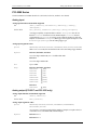
PCI-2500 Series.............................................................................................................................. 31
PCI-DAS6000 Series ...................................................................................................................... 38
PCI-DAS4020 Series ...................................................................................................................... 44
PCI-DAS64/Mx/16 Series................................................................................................................ 49
PCI- and CIO-DAS6402 and DAS3202 Series................................................................................ 52
PCI-DAS1602, PCI-DAS1200 & PCI-DAS1000 Series ................................................................... 56
PCIM-DAS1602 and PCIM-DAS16JR Series.................................................................................. 60
CIO-DAS800 Series ........................................................................................................................ 63
CIO-, PCI-, and PC104-DAS08 Series ............................................................................................ 65
CIO-DAS08/Jr and CIO-DAS08/Jr/16 Series .................................................................................. 68
PCM-DAS08 ................................................................................................................................... 70
PPIO-AI08 ....................................................................................................................................... 71
CIO- and PC104-DAS16 ................................................................................................................. 72
PCM- and PC-CARD-DAS16 Series ............................................................................................... 76
CIO-DAS1400 and CIO-DAS1600 Series ....................................................................................... 79
CIO-DAS48/PGA ............................................................................................................................ 82
miniLAB 1008.................................................................................................................................. 83
USB-1208 Series ............................................................................................................................ 87
USB-1408 Series ............................................................................................................................ 92
USB-1608FS ................................................................................................................................... 96
USB-1608HS, USB-1608HS-2AO................................................................................................... 99
USB-1616FS ................................................................................................................................. 103
USB-1616HS, USB-1616HS-2, and USB-1616HS-4 .................................................................... 107
USB-1616HS-BNC ........................................................................................................................ 114
USB-2500 Series .......................................................................................................................... 120
DEMO-BOARD ............................................................................................................................. 127
7 Analog Output Boards ......................................................................... 129
Introduction ................................................................................................................................... 129
DAC04 HS Series ......................................................................................................................... 130
DAC Series (Excluding HS Series) ............................................................................................... 131
PCI-DAC6700 Series .................................................................................................................... 132
PCM- and PC-CARD- DAC Series ................................................................................................ 133
PCIM- and CIO- DDA06 Series..................................................................................................... 134
PCI- and CPCI- DDA Series ......................................................................................................... 135
cSBX-DDA04 ................................................................................................................................ 136
USB-3100 Series .......................................................................................................................... 137
8 Digital Input/Output Boards ................................................................. 140
Introduction ................................................................................................................................... 140
Basic signed integers ................................................................................................................ 140
AC5 Series .................................................................................................................................... 141
DIO Series .................................................................................................................................... 142
DIO24/CTR3 and D24/CTR3 Series ............................................................................................. 143
PCI-DIO48/CTR15 ........................................................................................................................ 144
PCIe-DIO24 and PCIe-DIO96H .................................................................................................... 145
PDISO8 and PDISO16 Series....................................................................................................... 146
Establishing and requesting control of an E-PDISO16 .............................................................. 146
Sending a request for control of an E-PDISO16 ........................................................................ 147
Receiving a request for control of an E-PDISO16 ..................................................................... 147
Receiving a message ................................................................................................................ 147
CIO-PDMA16 and CIO-PDMA32 .................................................................................................. 148
USB-1024 and USB-DIO24 Series ............................................................................................... 149
USB-DIO96 Series (formerly USB-1096 Series) ........................................................................... 151
USB-SSR Series ........................................................................................................................... 153
Switch & Sense 8/8 ....................................................................................................................... 154
DEMO-BOARD ............................................................................................................................. 155
9 Digital Input Boards ............................................................................. 157
Introduction ................................................................................................................................... 157
CIO- and PC104- DI Series........................................................................................................... 158
CIO-DISO48.................................................................................................................................. 159
6
Universal Library User's Guide
10 Digital Output Boards .......................................................................... 160
Introduction ................................................................................................................................... 160
CIO-RELAY Series ....................................................................................................................... 161
USB-ERB Series ........................................................................................................................... 162
CIO- and PC104-DO Series .......................................................................................................... 163
11 Counter Boards .................................................................................... 164
Introduction ................................................................................................................................... 164
Visual Basic signed integers ..................................................................................................... 164
Counter chip variables............................................................................................................... 164
CTR Series ................................................................................................................................... 165
INT32 Series ................................................................................................................................. 167
PPIO-CTR06 ................................................................................................................................. 168
QUAD Series ................................................................................................................................ 169
USB-4300 Series .......................................................................................................................... 171
12 Expansion Boards ................................................................................ 173
Introduction ................................................................................................................................... 173
AI-EXP48 ...................................................................................................................................... 174
CIO-EXP Series ............................................................................................................................ 175
MEGA-FIFO .................................................................................................................................. 176
13 MetraBus Boards .................................................................................. 177
Introduction ................................................................................................................................... 177
MDB64 Series ............................................................................................................................... 178
MIO and MII Digital I/O ................................................................................................................. 179
MEM Series Relay ........................................................................................................................ 180
MSSR-24 SSR .............................................................................................................................. 181
14 Temperature Input Boards................................................................... 182
Introduction ................................................................................................................................... 182
CIO-DAS-TEMP ............................................................................................................................ 183
DAS-TC Series ............................................................................................................................. 184
USB-TEMP Series, USB-TC Series .............................................................................................. 185
USB-5203, USB-5201 ................................................................................................................... 188
WEB-TEMP, WEB-TC .................................................................................................................. 191
WLS Series ................................................................................................................................... 195
15 Other Hardware .................................................................................... 200
Introduction ................................................................................................................................... 200
COM422 Series ............................................................................................................................ 201
COM485 Series ............................................................................................................................ 201
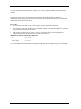
Appendix – Measurement Computing Device IDs ............................. 202
7
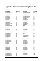
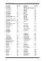
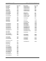
Table of MCC Hardware with UL Support
CPCI boards
CPCI-DIO24H ..................... 142
CPCI-DIO48H ..................... 142
CPCI-DIO96H ..................... 142
Ethernet boards
E-PDISO16 .................... 146–47
Expansion boards
AI-EXP48 ............................ 174
CIO-EXP16 ......................... 175
CIO-EXP32 ......................... 175
CIO-EXP-BRIDGE ............. 175
CIO-EXP-GP ....................... 175
CIO-EXP-RTD .................... 175
MEGA-FIFO ....................... 176
ISA boards
CIO-COM422 ...................... 201
CIO-COM485 ...................... 201
CIO-CTR05 ................... 165–66
CIO-CTR10 ................... 165–66
CIO-CTR10HD ............. 165–66
CIO-CTR20HD ............. 165–66
CIO-DAC02 ........................ 131
CIO-DAC02/16 ................... 131
CIO-DAC04/12-HS ............. 130
CIO-DAC04/16-HS ............. 130
CIO-DAC08 ........................ 131
CIO-DAC08/16 ................... 131
CIO-DAC08-I ...................... 131
CIO-DAC16 ........................ 131
CIO-DAC16/16 ................... 131
CIO-DAC16-I ...................... 131
CIO-DAS08 ..................... 65–67
CIO-DAS08/Jr ....................... 68
CIO-DAS08/Jr/16 .................. 68
CIO-DAS08/Jr/16-AO ........... 68
CIO-DAS08/Jr-AO ................ 68
CIO-DAS1401/12 ............ 79–81
CIO-DAS1402/12 ............ 79–81
CIO-DAS1402/16 ............ 79–81
CIO-DAS16 ..................... 72–75
CIO-DAS16/330 .............. 72–75
CIO-DAS16/330i ............. 72–75
CIO-DAS16/F .................. 72–75
CIO-DAS16/Jr ................. 72–75
CIO-DAS16/Jr/16 ............ 72–75
CIO-DAS16/M1 .............. 72–75
CIO-DAS16/M1/16 ......... 72–75
CIO-DAS1601/12 ............ 79–81
CIO-DAS1602/12 ............ 79–81
CIO-DAS1602/16 ............ 79–81
CIO-DAS48/PGA .................. 82
CIO-DAS48-I ........................ 82
CIO-DAS6402/12 ............ 52–55
CIO-DAS6402/16 ............ 52–55
CIO-DAS800 ................... 63–64
CIO-DAS801 ................... 63–64
CIO-DAS802 ................... 63–64
CIO-DAS802/16 .............. 63–64
CIO-DAS-TC....................... 184
CIO-DAS-TEMP ................. 183
CIO-DI192 ........................... 158
CIO-DI48 ............................. 158
CIO-DI96 ............................. 158
CIO-DIO192 ........................ 142
CIO-DIO24 .......................... 142
CIO-DIO24/CTR3 ............... 143
CIO-DIO24H ....................... 142
CIO-DIO48 .......................... 142
CIO-DIO48H ....................... 142
CIO-DIO96 .......................... 142
CIO-DISO48 ........................ 159
CIO-DO192H ...................... 163
CIO-DO24DD ..................... 163
CIO-DO48DD ..................... 163
CIO-DO48H ........................ 163
CIO-DO96H ........................ 163
CIO-DUAL422 .................... 201
CIO-DUAL-AC5 ................. 141
CIO-INT32 .......................... 167
CIO-PDISO16 ............... 146–47
CIO-PDISO8 ................. 146–47
CIO-PDMA16 ..................... 148
CIO-PDMA32 ..................... 148
CIO-QUAD02 ............... 169–70
CIO-QUAD04 ............... 169–70
CIO-RELAY08 .................... 161
CIO-RELAY16 .................... 161
CIO-RELAY16/M ............... 161
CIO-RELAY24 .................... 161
CIO-RELAY32 .................... 161
Demo-Board .....127–28, 155–56
ISA-MDB64 ........................ 178
Life support
devices/systems ............. 4
Memory boards
MEGA-FIFO ....................... 176
MetraBus boards
MEM-32 .............................. 180
MEM-8 ................................ 180
MSSR-24 ............................. 181
PC104 boards
PC104-AC5 ......................... 141
PC104-CTR10HD.......... 165–66
PC104-DAC06..................... 131
PC104-DAS08 ................. 65–67
PC104-DAS16Jr/12 ......... 72–75
PC104-DAS16Jr/16 ......... 72–75
PC104-DI48 ......................... 158
PC104-DIO48 ...................... 142
PC104-DO48H .................... 163
PC104-MDB64 .................... 178
PC104-PDISO8 ............. 146–47
8
PCI boards
PCI-2511.......................... 31–37
PCI-2513.......................... 31–37
PCI-2515.......................... 31–37
PCI-2517.......................... 31–37
PCI-CTR05 .................... 165–66
PCI-CTR10 .................... 165–66
PCI-CTR20HD .............. 165–66
PCI-DAC6702 ..................... 132
PCI-DAC6703 ..................... 132
PCI-DAS08...................... 65–67
PCI-DAS1000 .................. 56–59
PCI-DAS1001 .................. 56–59
PCI-DAS1002 .................. 56–59
PCI-DAS1200 .................. 56–59
PCI-DAS1200/JR ............ 56–59
PCI-DAS1602/12............. 56–59
PCI-DAS1602/16............. 56–59
PCI-DAS3202/16............. 52–55
PCI-DAS4020/12............. 44–48
PCI-DAS6013 .................. 38–43
PCI-DAS6014 .................. 38–43
PCI-DAS6023 .................. 38–43
PCI-DAS6025 .................. 38–43
PCI-DAS6030 .................. 38–43
PCI-DAS6031 .................. 38–43
PCI-DAS6032 .................. 38–43
PCI-DAS6033 .................. 38–43
PCI-DAS6034 .................. 38–43
PCI-DAS6035 .................. 38–43
PCI-DAS6036 .................. 38–43
PCI-DAS6040 .................. 38–43
PCI-DAS6052 .................. 38–43
PCI-DAS6070 .................. 38–43
PCI-DAS6071 .................. 38–43
PCI-DAS6402/12............. 52–55
PCI-DAS6402/16............. 52–55
PCI-DAS-TC ....................... 184
PCI-DIO24 .......................... 142
PCI-DIO24/LP ..................... 142
PCI-DIO24/S ....................... 142
PCI-DIO24H ........................ 142
PCI-DIO24H/CTR3 ............. 143
PCI-DIO48H ........................ 142
PCI-DIO48H/CTR15 ..... 144–46
PCI-DIO96 .......................... 142
PCI-DIO96H ........................ 142
PCI-DUAL-AC5 .................. 141
PCI-INT32 ........................... 167
PCIM-DAS1602/16 ......... 60–62
PCIM-DAS16JR/16 ......... 60–62
PCI-MDB64 ........................ 178
PCI-PDISO16 ................ 146–47
PCI-PDISO8 .................. 146–47
PCI-QUAD04 ................ 169–70
PCI-QUAD-AC5 ................. 141
Universal Library User's Guide
PCIe boards
PCIe-DIO24 ......................... 145
PCIe-DIO96H ...................... 145
PCMCIA cards
PC-CARD-D24/CTR3 ......... 143
PC-CARD-DAS16/12...... 76–78
PC-CARD-DAS16/12AO 76–78
PC-CARD-DAS16/16...... 76–78
PC-CARD-DAS16/16AO 76–78
PC-CARD-DAS16/330.... 76–78
PC-CARD-DIO48 ............... 142
PCM-D24/CTR3 .................. 143
PCM-DAS08 ......................... 70
PCM-DAS16D/12 ........... 76–78
PCM-DAS16D/12AO ...... 76–78
PCM-DAS16D/16 ........... 76–78
PCM-DAS16S/12 ............ 76–78
PCM-DAS16S/16 ............ 76–78
PCM-DAS16S/330 .......... 76–78
PCM-QUAD02 .............. 169–70
PPIO boards
PPIO-AI08 ............................. 71
PPIO-CTR06 ....................... 168
PPIO-DIO24 ........................ 142
USB devices
miniLAB 1008 ................. 83–86
Switch & Sense 8/8 .............. 154
USB-1024HLS............... 149–50
USB-1024LS ................. 149–50
USB-1096HFS ........ 151–52, See
USB-DIO96H
USB-1208FS.................... 87–91
USB-1208LS ................... 87–91
USB-1408FS.................... 92–95
USB-1608FS.................... 96–98
USB-1608HS ................. 99–102
USB-1608HS-2AO ........ 99–102
USB-1616FS.................... 103–6
USB-1616HS ................. 107–13
USB-1616HS-2 .............. 107–13
USB-1616HS-4 .............. 107–13
USB-1616HS-BNC........ 114–19
USB-2523 ...................... 113–26
USB-2527 ...................... 113–26
USB-2533 ...................... 113–26
USB-2537 ...................... 113–26
USB-3101 ...................... 137–39
USB-3102 ...................... 137–39
USB-3103 ...................... 137–39
USB-3104 ...................... 137–39
USB-3105 ...................... 137–39
USB-3106 ...................... 137–39
USB-3110 ...................... 137–38
USB-3112 ...................... 137–38
USB-3114 ...................... 137–38
USB-4301 ...................... 171–72
9
USB-4302 ...................... 171–72
USB-4303 ...................... 171–72
USB-4304 ...................... 171–72
USB-5201 ...................... 188–99
USB-5203 ...................... 188–99
USB-DIO24/37 .............. 149–50
USB-DIO24H/37 ........... 149–50
USB-DIO96H ................ 151–52
USB-DIO96H/50 ........... 151–52
USB-ERB08 ........................ 162
USB-ERB24 ........................ 162
USB-PDISO8................. 146–47
USB-PDISO8/40 ........... 146–47
USB-SSR08 ......................... 153
USB-SSR24 ......................... 153
USB-TC ......................... 185–87
USB-TC-AI ................... 185–87
USB-TEMP ................... 185–87
USB-TEMP-AI .............. 185–87
Web devices
WEB-TC ........................ 191–94
WEB-TEMP .................. 191–94
Wireless devices
WLS-IFC ....................... 195–99
WLS-TC ........................ 195–99
WLS-TEMP ................... 195–99
1
Introducing the Universal Library
Congratulations and thank you for selecting the Universal Library (UL). We believe it is the most
comprehensive and easiest-to-use data acquisition software interface available anywhere. As easy as
Universal Library is to use, significant documentation and explanation is still required to help new users get
going, and to allow previous users to take advantage of all the package's powerful features.
The fast changing nature of the software industry makes it very difficult to provide a totally up to date user
guide in written form. Adding to this complexity are the new features and functions that are constantly being
added to the library. To provide the most complete information possible and at the same time keep the
information current, the Universal Library documentation is offered in four parts:
Universal Library User's Guide: The User's Guide provides a general description of the UL, offers an
overview of the various features and functions, and discusses and how they can be used in different
operating systems and languages. The User's Guide also provides board-specific information relating to
the features and functions that are included with the Universal Library.
Universal Library Function Reference: The Function Reference contains detailed information about
the Universal Library functions, usage, and options. This document is available on our web site at
www.mccdaq.com/PDFmanuals/sm-ul-functions.pdf.
Example programs: The examples programs demonstrate the use of many of the most frequently used
functions, and are valuable learning tools. They are written for many popular languages. Each example
program is fully functional, and provides an ideal starting place for your own programming effort. You
can cut and paste from the example programs to create your own programs. It's easier to cut-and-paste
pieces from a known, working program than to start writing everything from scratch.
Readme files: The best way to get the latest, most up to date information is through Readme files. We
incorporate this information into our documentation as quickly as we can, but for the latest, greatest
information, read the Readme file.
Universal Library overview
The Universal Library is the software that you need to write your own programs for use with any of
Measurement Computing‘s data acquisition and control boards. The library is universal in three ways:
Universal across boards: The library contains high level functions for all of the common operations for all
boards. Each of the boards has different hardware but the Universal Library hides these differences from your
program. So, for example, a program written for use with one A/D board will work "as is" with a different
A/D board.
Universal across languages: The Universal Library provides the identical set of functions and arguments for
each supported language. If you switch languages, you will not have to learn a new library, with new syntax,
and different features.
If you are programming for the .NET framework, you will find that the Universal Library for .NET has the
same "look and feel" as the Universal Library for 32-bit windows applications, and is just as easy to program.
10
Universal Library User's Guide
Introducing the Universal Library
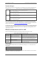
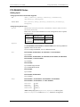
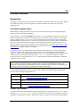
32-bit languages supported by the Universal Library at the time the library was released are listed in the
following table.
Microsoft Windows Languages
.NET Languages
Borland Windows Languages
Visual Basic
Visual C/C++
Quick C for Windows
Microsoft C
VB .NET
C# .NET
Borland C++
Borland C++ Builder
Delphi
Universal across platforms: The Universal Library provides the same sets of functions for Windows 2000,
Windows XP, and Windows Vista. Additionally, these functions have been extended to support the .NET
environment.
Windows Vista support
USB, PCI, WLS, and WEB devices are supported under Windows Vista. PCMCIA devices (PC-CARD and
PCM hardware) are not supported under Windows Vista.
11
2
Installation and Configuration
Installing the Universal Library
To install the Universal Library, follow the steps below.
1.
2.
3.
Place the Measurement Computing Data Acquisition Software CD in your CD drive.
The MCC DAQ dialog opens.
Select InstaCal & Universal Library and click the Install button.
Follow the installation instructions as prompted.
InstaCal is a powerful installation, test, and calibration software package that is installed with the Universal
Library application. Refer to the Quick Start Guide for examples of using InstaCal with Measurement
Computing's DEMO-BOARD.
The CB.CFG file and InstaCal
All board-specific information, including current installed options, is stored in the file CB.CFG file, which is
read by Universal Library. InstaCal creates and/or modifies this file when board configuration information is
added or updated. The Universal Library does not function without the CB.CFG file.
For this reason, you must use InstaCal to modify all board setups and configurations as well as to install or
remove boards from your system.
Installation – .NET support
Universal Library support for .NET requires that the Microsoft .NET framework already be installed on the
system before you install the Universal Library.
Licensing information
Each original copy of Universal Library is licensed for development use on one CPU at a time. It is theft to
make copies of this program for simultaneous program development.
Redistributing a custom UL application
The easiest way to distribute an application written with the Universal Library is to include a copy of
Measurement Computing's InstaCal installation package with the application. Instruct the end user to install
InstaCal before installing the application.
Some developers may want to integrate the installation of the required Universal Library drivers into the
custom application's installation. This should only be attempted by developers experienced in installation
development.
Following is an overview of the two methods.
12
Universal Library User's Guide
Installation and Configuration
Distributing InstaCal in addition to your custom UL application
If you create an application using the Universal Library, you may distribute the necessary runtime files
(Universal Library driver files) with the application royalty free. These files can be installed from
Measurement Computing's InstaCal installation package. To distribute a custom UL application, provide the
end user with two CDs or disks:
One CD or disk that contains Measurement Computing's InstaCal application. InstaCal must be installed
before the custom UL application.
One CD or disk that contains the setup program for their custom VB or C++ application.
You may not distribute any files that give the end user the ability to develop applications using the Universal
Library.
Integrating InstaCal into your custom UL installation CD or disk
For developers who wish to distribute their application on one CD, refer to the Universal Library
Redistribution Guide. This document contains procedures to merge the setup programs for both InstaCal and
the custom UL application into one setup program that you can distribute on one CD or disk. The merging
process is complicated — only experienced programmers should attempt to do this.
When you install the software, the Universal Library Redistribution Guide (ULRedistribution.pdf) is copied
to the default installation directory "C:\Program Files\Measurement Computing\DAQ\Documents" on your
local drive.
13
3
Getting Started
The Universal Library is callable from many languages and environments, including Visual Basic®, Visual
C++, Borland C++ Builder, and Delphi. A list of the languages currently supported by the Universal Library
is provided on page 11. Additionally, the UL is now callable from any language supported by the .NET
framework. This chapter describes how to use the library from each of the languages. The first section of the
chapter describes details of the library that apply to all languages. The following sections describe the
differences for each language.
Before starting your application, you should perform the following:
Set up and test your boards with InstaCal. The Universal Library will not function until InstaCal has
created a configuration file (CB.CFG).
Run the example programs for the language you program in.
Example programs
You can install example programs for supported languages when you install the Universal Library software. If
selected, the example programs are installed into the following installation subdirectories:
C
C#
CWIN
DELPHI
VB.NET
VBWIN
On Windows 2000 and Windows XP, the example programs are installed by default to \Program
Files\Measurement Computing\DAQ.
On Windows Vista, the example programs are installed by default to \Users\Public\Documents\Measurement
Computing\DAQ. When you install the example programs, an "Examples" shortcut is added to the directory
where you installed the Universal Library software. When selected, the directory containing the example
programs opens in Windows Explorer.
For a complete list of example programs, refer to the Universal Library Function Reference
The Universal Library Function Reference contains tables that list the UL and UL for .NET example
programs. Each table contains the name of the sample program and the functions that the program
demonstrates. This document is available on our web site at www.mccdaq.com/PDFmanuals/sm-ulfunctions.pdf.
14
4
Universal Library Description and Use
The Universal Library consists of a set of functions that are callable from your program. These functions are
grouped according to their purpose. All of the groups except for Miscellaneous are based on which type of
device they are used with.
Important - Read the UL documentation, Readme file, and run the example programs
In order to understand the functions, please read the board-specific information section contained in this
manual and in the Readme files supplied on the Universal Library disk. We also urge you to examine and run
one or more of the example programs supplied prior to attempting any programming of your own. Following
this advice can save you hours of frustration and wasted time.
General UL language interface description
The interface to all languages is a set of function calls and a set of constants. The list of function calls and
constants are identical for each language. All of the functions and constants are defined in a "header" file for
each language. Refer to the sections below, and especially to the example programs for each language. This
manual is brief with respect to details of language use and syntax. For more detailed information, review the
example programs. Example programs for each language are located in the installation directory.
Function arguments
Each library function takes a list of arguments and most return an error code. Some functions also return data
via their arguments. For example, one of the arguments to cbAIn() is the name of a variable in which the
analog input value will be stored. All function arguments that return data are listed in the "Returns" section of
the function description.
Constants
Many functions take arguments that must be set to one of a small number of choices. These choices are all
given symbolic constant names. For example, cbTIn() takes an argument called Scale that must be set to
CELSIUS, FAHRENHEIT, or KELVIN. These constant names are defined, and are assigned a value in the "header"
file for each language. Although it is possible to use the numbers rather than the symbolic constant names, we
strongly recommend that you use the names. Using constant names make your programs more readable and
more compatible with future versions of the library. The numbers may change in future versions, but the
symbolic names always remain the same.
Options arguments
Some library functions have an argument called Options. The Options argument is used to turn on and off
various optional features associated with the function. If you set Options = 0, the function sets all of these
options to the default value, or OFF.
Some options can have an alternative value, such as DTCONNECT and NODTCONNECT. If an option can have
more than one value, one of the values is designated as the default. Individual options can be turned on by
adding them to the Options argument. For example:
Options = BACKGROUND will turn on the "background execution" feature.
Options = BACKGROUND+CONTINUOUS will select both the "background execution" and the "continuous
execution" feature.
15
Universal Library User's Guide
Universal Library Description and Use
Error handling
Most library functions return an error code. If no errors occurred during a library call, 0 (or NOERRORS) is
returned as the error code. Otherwise, it is set to one of the codes listed in the Universal Library Function
Reference "Error Codes" chapter. This document is available on our web site at
www.mccdaq.com/PDFmanuals/sm-ul-functions.pdf.
If a non-zero error code is returned, you can use cbGetErrMsg() to convert the error code to a specific error
message. As an alternative to checking the error code after each function call, you can turn on the library's
internal error handling with cbErrHandling().
16-bit values using a signed integer data type
When using functions that require 16-bit values, the data is normally in the range of 0 to 65535. However,
some programming languages such as Visual Basic only provide signed data types. When using signed
integers, reading values above (32767) can be confusing.
The number (32767) in decimal is equivalent to (0111 1111 1111 1111) binary. The next increment (1000
0000 0000 0000) binary has a decimal value of (-32768). The maximum value (1111 1111 1111 1111)
binary translates to (-1) decimal. Keep this in mind if you are using Visual Basic (up to version 6) or other
languages that don‘t support unsigned integers.
There is additional information on this topic in the Universal Library Function Reference. This document is
available on our web site at www.mccdaq.com/PDFmanuals/sm-ul-functions.pdf. Also, refer to the
documentation supplied with your language compiler.
Using the Universal Library in Windows
All 32-bit applications (including console applications) access the 32-bit Windows Dynamic Link Library
(DLL) version of the Universal Library (CBW32.DLL). Example programs that illustrate the use of
CBW32.DLLs are provided for each supported language.
The Universal Library contains four functions for managing Windows global memory buffers:
cbWinBufAlloc()
cbWinBufFree()
cbWinArrayToBuf()
cbWinBufToArray()
Real-time acquisition under Windows
Real-time acquisition is available for Windows. To operate at full speed in Windows, the A/D board must
have an onboard FIFO buffer. All of our advanced designs have FIFO buffers, including our PCI-DAS boards
(except for the PCI-DAS08), and many of our CIO- boards, such as the CIO-DAS80x, CIO-DAS160x, CIODAS140x, and CIO-DAS16/330x. All of these data acquisition boards will operate at full speed in Windows.
Applying software calibration factors in real time on a per-sample basis eats up machine cycles. If your CPU
is slow, or if processing time is at a premium, withhold calibration until after the acquisition run is complete.
Turning off real-time software calibration saves CPU time during a high speed acquisition run.
Processor speed
Processor speed remains a factor for DMA transfers and for real-time software calibration. Processors of less
than a 150 megahertz (MHz) Pentium class may impose speed limits below the capability of the board (refer
to specific board information.)
16
Universal Library User's Guide
Universal Library Description and Use
If your processor is less than a 150 MHz Pentium and you need an acquisition speed in excess of 200 kilohertz
(kHz), use the NOCALIBRATEDATA option to a turn off real-time software calibration and save CPU time. After
the acquisition is run, calibrate the data with cbACalibrateData().
Visual Basic for Windows
To use the Universal Library with Visual Basic, include the Universal Library declaration file CBW.BAS in
your program. Include the file as a module in the project, or include it by reference inside those Forms which
call into the Universal Library. Once the declarations for the Universal Library have been added to your
project, call the library functions from any Form's event handlers.
For Visual Basic 6.0 and older, Windows memory buffers cannot be mapped onto arrays. As a consequence,
the cbWinArrayToBuf() and cbWinBufToArray() functions must be used to copy data between arrays and
Windows buffers.
Example:
Count = 100
MemHandle = cbWinBufAlloc (Count)
cbAInScan (......, MemHandle,...)
cbWinBufToArray (MemHandle, DataArray(0), 0, Count)
For i = 0 To Count
Print DataArray(i)
Next i
cbWinBufFree (MemHandle)
Visual Basic example programs
A complete set of Visual Basic example programs is included in the VBWIN folder of the Universal Library
installation directory. Each program illustrates the use of a Universal Library function from within a Visual
Basic program. The .FRM files contain the programs, and the corresponding .VBP files are the project files
used to build the programs for Visual Basic.
Microsoft Visual C++
To use the Universal Library with MS Visual C++, include the Universal Library header file CBW.H in your
C/C++ program and add the library file CBW32.LIB to your library modules for linking to the CBW32.DLL.
Microsoft Visual C++ example programs
The CWIN folder of the Universal Library installation directory contains three sample programs - Wincai01,
Wincai02 and Wincai03. Each program is an example of a simple C program that calls a few of the Universal
Library functions from a Windows application. Use the .DSP project files to build a 32-bit application.
The non-Windows C examples in the C folder of the installation directory provide a more complete set of
examples. You can compile these programs as 32-bit console applications for Windows by using the
MAKEMC32.BAT file.
Borland C /C++ for Windows
For 32-bit Borland (or Inprise) C/C++ compilers, include the Universal Library header file CBW.H in your
program and link with the import library file CBW32BC.LIB.
Borland C/C++ example programs
The non-Windows C examples provide an extensive set of examples. These can be compiled as 32-bit console
applications using the MAKEBC32.BAT file.
17
Universal Library User's Guide
Universal Library Description and Use
Delphi example programs
A complete set of Delphi example programs is included in the DELPHI folder of the Universal Library
installation directory. Each program illustrates the use of one Universal Library function from within a Delphi
program. The .PAS files contain the programs. The corresponding .DPR file is the Project file used to build
the program in a 32-bit Delphi environment.
In 32-bit Delphi environments use the cbw32.dll header. Where integers are passed by reference to a
Universal Library function, use the SmallInt data type in 32-bit environments. The relevant functions are
defined this way in the 32-bit header, so if you try to pass an Integer data type you will get a compiler error.
18
5
Universal Library for .NET Description & Use
Programming the Universal Library API is now available through the various languages supported by the
Microsoft .NET framework. All .NET applications access the 32-bit Windows Universal Library
(CBW32.DLL) through the MccDaq .NET assembly (MCCDAQ.DLL). The MccDaq assembly provides an
interface that exposes each Universal Library function that is callable from the .NET language.
The Universal Library for .NET is designed to provide the same "look and feel" as the Universal Library for
32-bit Windows. This design makes it easier to port over existing data acquisition programs, and minimizes
the learning curve for programmers familiar with the CBW32.DLL interface.
In the Universal Library for .NET, each function is exposed as a class method with virtually the same
parameter set as their UL counterparts.
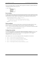
Configuring a UL for .NET project
In a .NET application, there are no header files to include in your project. You define methods and constants
by adding the MccDaq assembly, or Namespace, as a reference to your project. You access UL for .NET
methods through a class that has the Universal Library as a member.
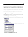
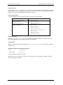
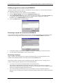
To add the MccDaq Namespace as a reference in a Visual Studio .NET project:
1.
2.
3.
4.
Start a new Visual Basic or C# project in Visual Studio .NET.
From the Visual Studio .NET Solution Explorer window, right-click on References and select Add
Reference.
The Add Reference window appears.
From the .NET tab, select the MccDaq option from the displayed list of .NET assemblies and click on the
Select button.
MccDaq displays in the Selected Components area on the window.
Click on the OK button.
19
Universal Library User's Guide
Universal Library for .NET Description & Use
MccDaq appears under the References folder in the Solution Explorer window.
The MccDaq Namespace is now referenced by your Visual Studio .NET project.
General UL for .NET language interface description
The MccDaq Namespace provides an interface that exposes each Universal Library for .NET method as a
member of a class with virtually the same parameters set as their UL counterparts. The MccDaq Namespace is
a logical naming scheme for grouping related types. The .NET Framework uses a hierarchical naming scheme
for grouping types into logical categories of related functionality.
When you develop a .NET application that uses the Universal Library, you add the MccDaq Namespace as a
reference to your project. There are no "header" files in a .NET project.
The MccDaq Namespace contains the classes and enumerated values by which UL for .NET applications
access the Universal Library data types and functions. The MccDaq Namespace contains five main classes:
MccBoard class
ErrorInfo class
MccService class
GlobalConfig class
DataLogger class
The MccDaq assembly allows you to design Common Language Specification (CLS)-compliant programs. A
CLS-compliant program contains methods that can be called from any existing or future language developed
for the Microsoft .NET framework. Use CLS-compliant data types to ensure future compatibility.
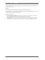
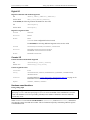
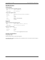
MccBoard class
The MccBoard class provides access to all of the methods for data acquisition and properties providing board
information and configuration for a particular board.
Class Constructors
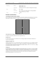
The MccBoard class provides two constructors; one which accepts a board number argument and one with no
arguments.
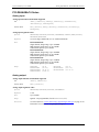
The following code examples demonstrate how to create a new instance of the MccBoard class using the latter
version with a default board number of 0:
Visual Basic
C#
Private DaqBoard As MccDaq.MccBoard
DaqBoard = New MccDaq.MccBoard()
private MccDaq.MccBoard DaqBoard;
DaqBoard = new MccDaq.MccBoard();
20
Universal Library User's Guide
Universal Library for .NET Description & Use
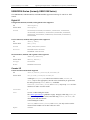
The following code examples demonstrate how to create a new instance of the MccBoard class with the board
number passed to it:
Visual Basic
C#
Private DaqBoard As MccDaq.MccBoard
DaqBoard = New MccDaq.MccBoard(BoardNumber)
private MccDaq.MccBoard DaqBoard;
DaqBoard = new MccDaq.MccBoard(BoardNumber);
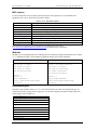
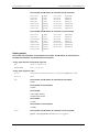
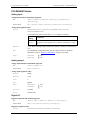
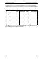
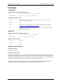
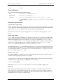
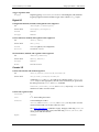
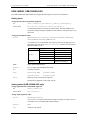
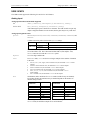
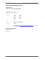
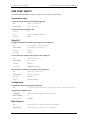
Class properties
The MccBoard class also contains six properties that you can use to examine or change the configuration of
your board. The configuration information for all boards is stored in the CB.CFG file, and is loaded from
CB.CFG by all programs that use the library.
Properties
Description
BoardName
BoardNum
BoardConfig
Name of the board associated with an instance of the MccBoard class.
Number of the board associated with an instance of the MccBoard class.
Gets a reference to a cBoardConfig class object. Use this class reference to get or set
various board settings.
Gets a reference to a cCtrConfig class object. Use this class reference to get or set
various counter settings.
Gets a reference to a cDioConfig class object. Use this class reference to get or set
various digital I/O settings.
Gets a reference to a cExpansionConfig class object. Use this class reference to get or set
various expansion board settings.
CtrConfig
DioConfig
ExpansionConfig
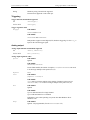
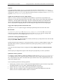
Class methods
The MccBoard class contains close to 80 methods that are equivalents of the function calls used in the standard
Universal Library. The MccBoard class methods have virtually the same parameters set as their UL
counterparts.
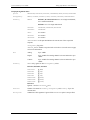
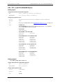
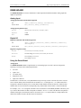
The following code examples demonstrate how to call the AIn()method of the MccBoard object MccDaq:
Visual Basic
ULStat = DaqBoard.AIn(Chan, Range, DataValue)
C#
ULStat = DaqBoard.AIn(Chan, Range, out DataValue);
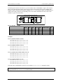
Many of the arguments are MccDaq enumerated values. Enumerated values take settings such as range types
or scan options and put them into logical groups. For example, to set a range value, reference a value from the
MCCDaq.Range enumerated type, such as Range.Bip5Volts. Refer to Table 1 on page 23 for a list of MccDaq
enumerated values.
The Universal Library Function Reference contains detailed information about all MccBoard class methods.
This document is available on our web site at www.mccdaq.com/PDFmanuals/sm-ul-functions.pdf.
ErrorInfo class
Most UL methods return ErrorInfo objects. These objects contain two properties that provide information on
the status of the method called:
ErrorInfo.Message property gets the text of the error message associated with a specific error code.
ErrorInfo.Value property gets the named constant value associated with the ErrorInfo object.
The ErrorInfo class also includes error code enumerated values, which define the error number and
associated message which can be returned when you call a method.
21
Universal Library User's Guide
Universal Library for .NET Description & Use
MccService class
The MccService class contains all members for calling utility UL functions. This class contains the following
static methods (you do not need to create an instance of the MccService class to call these methods):
DeclareRevision()
ErrHandling()
FileGetInfo()
FileRead()
GetBoardName()
GetRevision()
WinArrayToBuf()
WinBufAlloc()
WinBufAlloc32()
WinBufFree()
WinBufToArray()
WinBufToArray32()
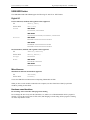
The following code examples demonstrate how to call a UL for .NET memory management method from
within a Universal Library program:
WindowHandle=MccService.WinBuffAlloc(1000)
MccService.WinBuffFree(WindowHandle)
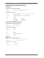
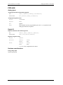
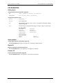
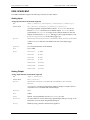
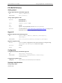
GlobalConfig class
The GlobalConfig class contains all of the members for getting global configuration information. This class
contains three properties:
MccDaq.GlobalConfig.NumBoards property returns the maximum number of boards that you can install
at one time. ConfigGlobal=MccDaq.GlobalConfig.NumBoards
MccDaq.GlobalConfig.NumExpBoards property returns the maximum number of expansions boards that
are allowed to be installed on the board. ConfigGlobal=MccDaq.GlobalConfig.NumExpBoards
MccDaq.GlobalConfig.Version property is used to determine compatibility with the library version.
ConfigGlobal=MccDaq.GlobalConfig.Version
Each of these properties is typed as an Integer.
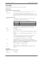
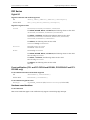
DataLogger Class
The DataLogger class contains all members for reading and converting the data contained in binary log files.
This class contains one property and 14 methods:
FileName property returns the file name associated with an instance of the DataLogger class.
ConvertFile() converts a binary log file to a comma-separated values (.CSV) text file or another text
file format that you specify.
GetAIChannelCount() retrieves the total number of analog channels that were logged in a binary file.
GetAIInfo() retrieves the channel number and unit value of each analog input channel logged in a binary
file.
GetCJCInfo() retrieves the number of CJC temperature channels logged in a binary file.
GetDIOInfo() retrieves the number of digital I/O channels logged in a binary file.
GetFileInfo() retrieves the version level and byte size of a binary file.
22
Universal Library User's Guide
Universal Library for .NET Description & Use
GetFileName() retrieves the name of the nth file in the directory containing binary log files.
GetPreferences retrieves API preference settings for time stamp data, analog temperature data, and CJC
temperature data. Returns the default values unless changed using SetPreferences().
GetSampleInfo() retrieves the sample interval, sample count, and the date and time of the first data point
in a binary file.
ReadAIChannels() retrieves analog input data from a binary file, and stores the values in an array.
ReadCJCChannels() retrieves CJC temperature data from a binary file, and stores the values in an array.
ReadDIOChannels()retrieves digital I/O channel data from a binary file, and stores the values in an array.
ReadTimeTags() retrieves date and time values logged in a binary file. This method stores date values in
the dateTags array, and time values in the timeTags array.
SetPreferences() sets formatting preferences for returned time stamp data, analog data, and CJC
temperature data.
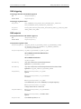
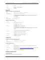
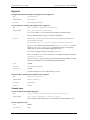
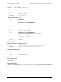
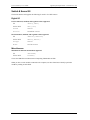
The following code examples demonstrate how to use the GetFileName()method from within a Universal
Library program to retrieve the name of a binary log file:
Visual Basic
C#
Status = DataLogger.GetFileName(MccService.GetFirst, path, filename)
status = DataLogger.GetFileName(MccService.GetFirst, ref path,
ref filename);
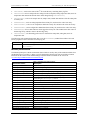
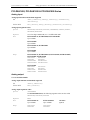
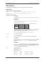
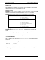
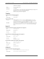
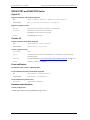
MccDaq enumerations
The MccDaq Namespace contains enumerated values which are used by many of the methods available from
the MccDaq classes (see Table 1). Refer to specific method descriptions in the Universal Library Function
Reference for the values of each enumerated type. This document is available on our web site at
www.mccdaq.com/PDFmanuals/sm-ul-functions.pdf.
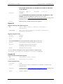
Table 1. MccDaq Enumerated Values
Enumeration Name
Description
MccDaq.BCDMode
MccDaq.C8254Mode
MccDaq.C8536OutputControl
MccDaq.C8536TriggerType
MccDaq.C9513OutputControl
MccDaq.CompareValue
MccDaq.ConnectionPin
Lists BCD mode options (enabled/disabled).
Lists all of the operating modes for 8254 counters.
Lists all of the types of output from an 8536 counters.
Lists all of the options for specifying the trigger type for 8536 counters.
List all of the types of output from a 9513 counters.
List all options for comparing values while configuring a 9513 counter.
Defines the connector pins to associate with the signal type and direction
when calling the SelectSignal() method.
Defines the possible state of each counter channel (enabled/disabled).
Defines the count direction when configuring counters.
Defines the edge used for counting.
Lists all of the register names used to load counters.
Lists all counter input sources.
Lists all valid modes for a C7266 counter configuration.
Lists all of the options for linking counter 1 to counter 2.
Defines the available DAC update modes
Lists the format of the data that is returned by a counter.
Configures a digital I/O port as input or output.
Defines all digital logic states.
Defines all digital port types.
Lists all modes to transfer to/from the memory boards.
Defines all error handling options.
Defines all error constants.
MccDaq.CounterControl
MccDaq.CountDirection
MccDaq.CountEdge
MccDaq.CounterRegister
MccDaq.CounterSource
MccDaq.CountingMode
MccDaq.CtrlOutput
MccDaq.DACUpdate
MccDaq.DataEncoding
MccDaq.DigitalPortDirection
MccDaq.DigitalLogicState
MccDaq.DigitalPortType
MccDaq.DTMode
MccDaq.ErrorHandling
MccDaq.ErrorInfo.ErrorCode
23
Universal Library User's Guide
Universal Library for .NET Description & Use
Enumeration Name
Description
MccDaq.ErrorReporting
MccDaq.EventType
MccDaq.FieldDelimiter
Defines all error reporting options.
Lists all available event conditions.
Lists all options for specifying the delimiter character used to separate fields
in a converted binary log file.
Lists all signals types that can be routed to the FLG1 and FLG2 pins on the
7266 counters.
List all valid function types used with data acquisition methods.
List all of the gating modes for configuring a 9513 counter.
List the actions to be taken when the index signal is received by a 7266
counter.
Lists the options used to specify the units for analog data in a binary file
Enables or disables various options.
Defines digital port types for bit level configuration.
Defines digital port types for bit level input/output methods.
Lists all of the resolution multipliers for quadrature input.
Defines the set of ranges within the UL for A/D and D/A operations.
Lists the recycle mode options for 9513 and 8536 counters.
Lists the options for reloading the 9513 counter.
List the available scan options for paced input/output methods.
List all signal types associated with a connector pin on boards supporting a
DAQ-Sync connector.
Lists all of the directions available from a specified signal type assigned to a
connector pin.
List all available polarities for a specified signal.
List all of the signal sources of the signal from which the frequency will be
calculated.
Defines trigger types for software triggering.
List all status bits available when reading counter status.
Lists the options used to specify the units for analog data in a converted file.
Lists all options for specifying the time format of timestamp data.
List all time of day options for initializing a 9513 counter.
Lists all options for specifying the time zone of timestamp data
List all valid trigger types for the MccBoard.SetTrigger method.
Specifies whether or not to apply smoothing to temperature readings.
MccDaq.FlagPins
MccDaq.FunctionType
MccDaq.GateControl
MccDaq.IndexMode
MccDaq.LoggerUnits
MccDaq.OptionState
MccDaq.PrimaryBitConfigPortType
MccDaq.PrimaryDigitalPortType
MccDaq.Quadrature
MccDaq.Range
MccDaq.RecycleMode
MccDaq.Reload
MccDaq.ScanOptions
MccDaq.SignalType
MccDaq.SignalDirection
MccDaq.SignalPolarity
MccDaq.SignalSource
MccDaq.SoftwareTriggerType
MccDaq.StatusBits
MccDaq.TempScale
MccDaq.TimeFormat
MccDaq.TimeOfDay
MccDaq.TimeZone
MccDaq.TriggerType
MccDaq.ThermocoupleOptions
24
Universal Library User's Guide
Universal Library for .NET Description & Use
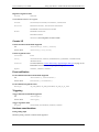
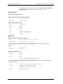
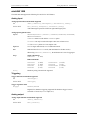
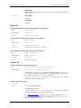
Parameter data types
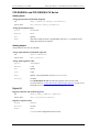
Many of the Universal Library for .NET methods are overloaded to provide for signed or unsigned data types
as parameters. The AConvertData() method is shown below using both signed and unsigned data types.
VB.NET
Public Function AConvertData(ByVal numPoints As Integer, ByRef adData As
Short, ByRef chanTags As Short) As MccDaq.ErrorInfo
Member of MccDaq.MccBoard
Public Function AConvertData(ByVal numPoints As Integer, ByRef adData As
System.UInt16, ByRef chanTags As System.UInt16) As MccDaq.ErrorInfo
Member of MccDaq.MccBoard
C# .NET
public MccDaq.ErrorInfo AConvertData (System.Int32 numPoints, System.Int16
adData, System.Int16 chanTags)
Member of MccDaq.MccBoard
public MccDaq.ErrorInfo AConvertData (System.Int32 numPoints, System.UInt16
adData, System.UInt16 chanTags)
Member of MccDaq.MccBoard
For most data acquisition applications, unsigned data values are easier to manage. However, since Visual
Basic (version 6 and earlier) does not support unsigned data types, it may be easier to port these programs to
.NET if the signed data types are used for the method parameters. For additional information on using signed
data types, refer to the section ―16-bit values using a signed integer data type‖ on page 16.
The short (Int16) data type is Common Language Specification (CLS) compliant, is supported in VB, and will
be included in any future .NET language developed for the .NET framework. Using CLS-compliant data types
ensures future compatibility. Unsigned data types are not CLS compliant, but are still supported by various
.NET languages, such as C#.
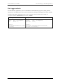
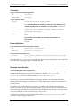
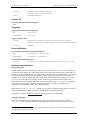
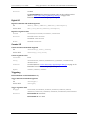
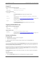
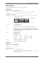
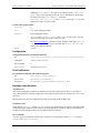
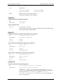
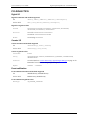
Differences between the UL and UL for .NET
Table 2 lists the differences between the Universal Library and the Universal Library for .NET.
Table 2. Differences between UL and UL for .NET
Board Number
Functions
Constants
Return value
Universal Library
Universal Library for .NET
The board number is included as a
parameter to the board functions.
Set of function calls defined in a header.
An MccBoard class is created for each board installed,
and the board number is passed to that board class.
Set of methods. Methods of MccBoard or MccService
classes. To access a method, instantiate a UL for .NET
class and call the appropriate method using that class.
Constants are defined as enumerated types.
Constants are defined and assigned a
value in the "header" file.
The return value is an Error code.
The return value is an ErrorInfo object that contains the
error's number and message.
Board number
In a .NET application, multiple boards may be programmed by creating an MccBoard Class object for each
board installed:
Board0 = new MccBoard(0)
Board1 = new MccBoard(1)
Board2 = new MccBoard(2)
Note that the board number may be passed into the MccBoard class, which eliminates the need to include the
board number as a parameter to the board methods.
25
Universal Library User's Guide
Universal Library for .NET Description & Use
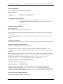
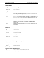
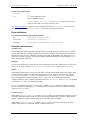
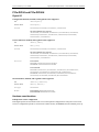
MCC classes
To use board-specific Universal Library functions inside a .NET application, you use methods of the
appropriate class. UL for .NET classes are listed in Table 3.
Table 3. UL for .NET Board Classes
UL for .NET Class
Description
MccBoard
ErrorInfo
BoardConfig
CtrConfig
DioConfig
ExpansionConfig
GlobalConfig
MccService
DataLogger
Access board-related Universal Library functions.
Utility class for storing and reporting error codes and messages.
Gets and sets board configuration settings.
Gets and sets counter configuration settings.
Gets and sets digital I/O configuration settings.
Gets and sets expansion board configuration settings.
Gets and sets global configuration settings.
Access utility Universal Library functions.
Reads and converts binary log files.
Refer to the Universal Library Function Reference (available on our web site at
www.mccdaq.com/PDFmanuals/sm-ul-functions.pdf) for additional class information.
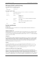
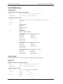
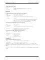
Methods
Methods are accessed through the class containing them. The following example demonstrates how to call the
AIn() method from within a 32-bit Windows application and also from a .NET application.
VB Application using CBW32.DLL
VB .NET Application using MCCDAQ.DLL
Dim
Dim
Dim
Dim
Dim
Dim Board0 As MccBoard
Board0 = new MccDaq.MccBoard(0)
Dim Channel As Integer
Dim Range As MccDaq.Range
Dim ULStat As ErrorInfo
Dim DataValue As UInt16
Board As Integer
Channel As Integer
Range As Integer
ULStat As Integer
DataValue As Short
Board =0
Channel = 0
Range =BIP5VOLTS;
ULStat =cbAIn(Board, Channel, Range,
DataValue)
Channel = 0
Range =Range.BIP5VOLTS;
ULStat =Board0.AIn(Channel, Range,
DataValue)
Enumerated types
Instead of using constants such as BIP5VOLTS, the Universal Library for .NET uses enumerated types. An
enumerated type takes settings such as range types, scan options or digital port numbers and puts them into
logical groups. Some examples are:
Range.Bip5Volts
Range.Bip10Volts
Range.Uni5Volts
Range.Uni10Volts
ScanOptions.Background
ScanOptions.Continuous
ScanOptions.BurstMode
TimeZone.GMT
FileType.Text
26
Universal Library User's Guide
Universal Library for .NET Description & Use
If you are programming inside of Visual Studio .NET, the types that are available for a particular enumerated
value display automatically when you type code:
Error handling
For .NET applications, the return value for the Universal Library functions is an object (ErrorInfo), rather than
a single integer value. The ErrorInfo object contains both the numeric value for the error that occurred, as well
as the associated error message. Within a .NET application, error checking may be performed as follows:
ULStat=Board0.AIn(Channel, Range, DataValue)
'check the numeric value of ULStat
If Not ULStat.Value = ErrorInfo.ErrorCode.NoErrors Then
'if there was an error, then display the error message
MsgBox ULStat.Message
EndIf
Service methods
You can access other Universal Library functions that are not board-specific through the MccService class.
This class contains a set of static methods you can access directly, without having to instantiate an
MccService object. The following examples demonstrate library calls to .NET memory management methods:
WindowHandle = MccService.WinBuffAlloc(1000)
MccService.WinBuffFree(WindowHandle)
Configuration methods
In 32-bit Windows applications, you access board configuration information by calling the cbGetConfig and
cbSetConfig API functions. In .NET applications, you access board configuration information through
separate classes, such as cBoardConfig, cCtrConfig, cDioConfig, and cExpansionConfig. Each
configuration item has a separate get and set method.
Some examples of how to access board configuration within a .NET application are shown below:
UlStat = Board0.BoardConfig.GetRange(RangeValue)
UlStat = Board1.DioConfig.GetNumBits(DevNumber, Number)
UlStat = Board2.CtrConfig.GetCtrType(DevNumber, CounterType)
UlStat = Board3.BoardConfig.SetClock(ClockSource)
UlStat = Board4.ExpansionConfig.SetCJCChan(DevNumber, CjcChan)
27
Universal Library User's Guide
Universal Library for .NET Description & Use
Data Logger methods
In 32-bit Windows applications, you access information contained in binary log files by calling the API
functions. In .NET applications, you access this information by calling the DataLogger class and its methods.
The following example demonstrates how to retrieve the name of the first binary log file using the
cbLogGetFileName() function and GetFileName() method.
C/C++ application
C# application
char
char*
int
string
string
ErrorInfo
filename(50);
path = "C:\\LogData";
retval = 0;
retval =
cbLogGetFileName(GetFirst, path,
filename);
filename = new string('\0',50);
path = "C:\\LogData";
status;
status =
DataLogger.GetFileName(MccService.GetFirst,
ref path, ref filename);
28
6
Analog Input Boards
Introduction
All boards that have analog input support the cbAIn()/AIn() and cbAInScan()/AInScan() functions, except
expansion boards, which only support cbAIn(). Boards released after the printing of this manual are described
in Readme files contained on the Universal Library disk.
When hardware-paced A/D conversion is not supported, cbAInScan()/AInScan() loops through software
paced conversions. The scan will execute at the maximum speed possible. This speed will vary with CPU
speed. The only valid option in this case is CONVERTDATA.
Concurrent analog input and output for paced analog inputs, paced analog outputs
For boards with both paced analog inputs and paced analog outputs, concurrent analog input and output scans
are supported. That is, these boards allow operations with analog input functions (cbAInScan/AInScan() and
cbAPretrig/APretrig) and analog output functions (cbAOutScan/AOutScan()) to overlap without having to
call cbStopBackground()/StopBackground() between the start of input and output scans.
Trigger support
Digital trigger
If trigger support is "Polled gate" (as opposed to "Hardware"), you implement a trigger by gating the on-board
pacer. This disables the on-board pacer. The trigger input is then polled continuously until the trigger occurs.
When that happens, the software disables the gate input so that when the trigger returns to its original state, it
does not affect the pacer, and acquisition continues until the requested number of samples has been acquired.
There are two side effects to this type of trigger:
The polling portion of the function does not occur in the background, even if the BACKGROUND option was
specified (although the actual data acquisition does).
The trigger does not necessarily occur on the rising edge. Acquisition can start at any time after the
function is called if the trigger input is at "active" level. For this reason, it is best to use a trigger that goes
active for a much shorter time than it is inactive.
Similar to ‗Polled gate‘ triggering is ‗Polled digital input‘ triggering, where the pacer is disabled while the
state of a digital input is polled. When the state changes to active, the pacer is enabled by the software. The
polled digital input trigger type limitations are very similar to the polled gate type explained above.
Analog trigger
You set up the trigger levels for an analog trigger using the function cbSetTrigger / SetTrigger, and passing
the appropriate values to the HighThreshold and LowThreshold arguments.
For most boards that support analog triggering, you can calculate the HighThreshold and LowThreshold
values by passing the required trigger voltage level and the appropriate Range to the cbFromEngUnits /
FromEngUnits function.
However, for some boards, you must manually calculate HighThreshold and LowThreshold. If a board
requires manual calculation, that information will be included in the Trigger information for the specific
product in this section. The procedure for manually calculating these values is detailed in the Universal
Library Function Reference in the description of the cbSetTrigger / SetTrigger function.
29
Universal Library User's Guide
Analog Input Boards
Pretrigger implementations
Pretrigger functionality may be implemented through software or hardware. These two methods have different
limitations and requirements. Most Measurement Computing products with pretrigger capability are
implemented in hardware.
When implemented in hardware, the buffer created using cbWinBufAlloc() must be large enough to hold 512
samples more than the requested TotalCount. The trigger location is tracked by a counter on the board. When
the trigger condition is met, data is acquired and the library functions return the actual number of pretrigger
points that were acquired. When run in BACKGROUND mode, the cbGetStatus() function will typically show
CurCount rise to the value of PretrigCount and remain there while CurIndex cycles from 0 to TotalCount
continuously until the trigger is received.
With the software implementation of pretrigger, the additional space in the buffer is not required. The trigger
location is tracked by software. Any triggers that occur before the number of samples defined by the
pretrigger count argument are ignored. When run in BACKGROUND mode, the cbGetStatus() function will
typically show CurCount at a value of 0 and CurIndex at a value of -1 until the trigger is received. They will
then rise from of PretrigCount to TotalCount.
Sampling rate using SINGLEIO
When using this mode of data transfer, the maximum analog sampling rate is dependent on the speed of the
computer in which the board is installed. In general, it is in the range of 5 to 50 kHz. If the requested speed
cannot be sustained, an overrun error will occur. Data will be returned, but likely there will be gaps. Some
boards, such as the CIO-DAS08, support this mode only, so the maximum rate attainable with these boards is
system-dependent.
30
Universal Library User's Guide
Analog Input Boards - PCI-2500 Series
PCI-2500 Series
The PCI-2500 Series includes the PCI-2511, PCI-2513, PCI-2515, and PCI -2517 boards.
Analog input
Analog input functions and methods supported
UL:
cbAIn(), cbAInScan(), cbFileAInScan(), cbAPretrig()*, cbATrig(),
cbALoadQueue()
UL for .NET:
AIn(), AInScan(), FileAInScan(), APretrig()*, ATrig(), ALoadQueue()
* Pretrigger capability is implemented in software. PretrigCount must be less
than the TotalCount and cannot exceed 100000 samples. TotalCount must be
greater than the PretrigCount. If a trigger occurs while the number of collected
samples is less than the PretrigCount, that trigger will be ignored. Requires a call
to cbSetTrigger (SetTrigger) for the analog trigger type.
Analog input argument values
Options
BACKGROUND, CONTINUOUS, EXTCLOCK, CONVERTDATA, DMAIO, BLOCKIO, EXTTRIGGER
With EXTTRIGGER mode, the first channel in the scan is the analog trigger channel.
HighChan
PCI-2517, PCI-2515, PCI-2513:
0 to 15 in single-ended mode, 0 to 7 in differential mode
PCI-2511:
0 to 15 in single-ended mode.
Rate
Up to 1 MHz
Range
PCI-2517, PCI-2515, PCI-2513:
BIP10VOLTS
( 10 V)
BIP5VOLTS
( 5 V)
BIP2VOLTS
( 2 V)
BIP1VOLTS
( 1 V)
BIPPT5VOLTS
( 0.5 V)
BIPPT2VOLTS
( 0.2 V)
BIPPT1VOLTS
( 0.1 V)
PCI-2511:
BIP10VOLTS
( 10 V)
Analog output (PCI-2517 and PCI-2515 only)
Analog output functions and methods supported
UL:
cbAOut(), cbAOutScan()
UL for .NET:
AOut(), AOutScan()
Analog output argument values
Options
BACKGROUND, CONTINUOUS, EXTCLOCK, SIMULTANEOUS, NONSTREAMEDIO,
ADCCLOCKTRIG, ADCCLOCK
NONSTREAMEDIO can only be used with the number of samples set equal to the size
of the FIFO or less. The FIFO holds 524288 samples.
HighChan
PCI-2517: 0 to 3
PCI-2515: 0 to 1
31
Universal Library User's Guide
Analog Input Boards - PCI-2500 Series
Rate
1 MHz
Range
Ignored - Not programmable; fixed at BIP10VOLTS ( 10 volts)
DataValue
0 to 65535 (Refer to "16-bit values using a signed integer data type" on page 16 for
information on 16-bit values using unsigned integers).
Pacing
Hardware pacing, external or internal clock supported.
Digital I/O
Configuration functions, methods, and argument values supported
UL:
cbDConfigPort()
UL for .NET:
DConfigPort()
PortNum
FIRSTPORTA, FIRSTPORTB, FIRSTPORTC
PortType
FIRSTPORTA
Port I/O functions, methods, and argument values supported
UL:
cbDIn(), cbDOut(), cbDInScan(), cbDOutScan()*
UL for .NET:
DIn(), DOut(), DInScan(), DOutScan()*
*FIRSTPORTA and FIRSTPORTB must be set for output to use this function. Refer to
DIO PortNum on page 37 for more information.
Options
BACKGROUND, CONTINUOUS, EXTCLOCK, EXTTRIGGER, WORDXFER, NONSTREAMEDIO,
ADCCLOCKTRIG, ADCCLOCK
The EXTTRIGGER option can only be used with the cbDInScan() function. You can
use the cbSetTrigger() function to program the trigger for rising edge, falling
edge, or the level of the digital trigger input (TTL).
The WORDXFER option can only be used with FIRSTPORTA.
The NONSTREAMEDIO, ADCCLOCKTRIG, and ADCCLOCK options can only be used with
the cbDOutScan() function.
The NONSTREAMEDIO option can only be used with the number of samples set equal
to the size of the FIFO or less. The FIFO holds 524288 samples.
Rate
12 MHz
PortNum
FIRSTPORTA, FIRSTPORTB, FIRSTPORTC
DataValue
0 to 255
0 to 65535 using the WORDXFER option with FIRSTPORTA
Bit I/O functions, methods, and argument values supported
UL:
cbDBitIn(), cbDBitOut()
UL for .NET:
DBitIn(), DBitOut()
PortType
FIRSTPORTA
BitNum
0 to 23
32
Universal Library User's Guide
Analog Input Boards - PCI-2500 Series
Counter input
Counter functions and methods supported
UL:
cbCIn(), cbCIn32(), cbCConfigScan(), cbCInScan(), cbCClear()
UL for .NET:
CIn(), CIn32(), CConfigScan(), CInScan(), CClear()
Note: Counters on these boards are zero-based (the first counter number is "0").
Counter argument values
Rate
6 MHz
CounterNum
0 to 3
Options
BACKGROUND, CONTINUOUS, EXTTRIGGER
You can use the cbSetTrigger() function to program the trigger for rising edge,
falling edge, or the level of the digital trigger input (TTL).
LoadValue
0 to 65535 (Refer to "16-bit values using a signed integer data type" on page 16 for
information on 16-bit values using unsigned integers.)
Timer output
Timer functions and methods supported
UL:
cbTimerOutStart(), cbTimerOutStop()
UL for .NET:
TimerOutStart(), TimerOutStop()
Timer argument values
TimerNum
0 to 1
Frequency
15.260 Hz to 1.0 MHz
Triggering
Trigger functions and methods supported
UL:
cbSetTrigger()
UL for .NET:
SetTrigger()
Trigger argument values
TrigType
TRIGABOVE, TRIGBELOW, TRIGHIGH, TRIGLOW, TRIGPOSEDGE, TRIGNEGEDGE
Digital triggering (TRIGHIGH, TRIGLOW, TRIGPOSEDGE, TRIGNEGEDGE) is not
supported for pre-trigger acquisitions (cbAPretrig() function). Analog triggering
(TRIGABOVE, TRIGBELOW) is not supported for the cbDInScan() function and the
cbCInScan() function.
Threshold
Analog hardware triggering, 12-bit resolution:
0 to 4095 (supported for cbAInScan() only)
Analog software triggering, 16-bit resolution:
0 to 65535 (supported for cbAPretrig() only)
DAQ input
DAQ input functions and methods supported
UL:
cbDaqInScan()
UL for .NET:
DaqInScan()
33
Universal Library User's Guide
Analog Input Boards - PCI-2500 Series
DAQ input argument values
Options
BACKGROUND, CONTINUOUS, EXTCLOCK, CONVERTDATA, DMAIO, BLOCKIO, EXTTRIGGER
ChanTypeArray
ANALOG, DIGITAL8, DIGITAL16, CTR16, CTR32LOW, CTR32HIGH, SETPOINTSTATUS
ChanArray
ANALOG:
PCI-2517, PCI-2515, PCI-2513: 0 to 15 in single-ended mode,
0 to 7 in differential mode
PCI-2511: 0 to 15 in single-ended mode
DIGITAL8:
FIRSTPORTA, FIRSTPORTB, FIRSTPORTC
DIGITAL16:
FIRSTPORTA
CTR16:
0-3 counters
CTR32LOW:
0-3 counters
CTR32HIGH:
0-3 counters
SETPOINTSTATUS: 16-bit port that indicates the current state of the 16 possible
setpoints.
ChanTypeArray flag value:
SETPOINT_ENABLE: Enables a setpoint. Refer to Hardware Considerations on page
36 for more information.
Rate
GainArray
Analog:
Up to 1 MHz
Digital:
Up to 12 MHz if no analog channel is selected. Otherwise up to
1 MHz.
Counter:
Up to 12 MHz if no analog channel is selected. Otherwise up to
1 MHz.
ANALOG only; ignore for other ChanTypeArray values.
PCI-2517, PCI-2515, PCI-2513:
BIP10VOLTS
BIP5VOLTS
BIP2VOLTS
BIP1VOLTS
BIPPT5VOLTS
BIPPT2VOLTS
BIPPT1VOLTS
(
(
(
(
(
(
(
10 V)
5 V)
2 V)
1 V)
0.5 V)
0.2 V)
0.1 V)
PCI-2511:
Ignored – fixed at BIP10VOLTS ( 10 V)
ChanCount
Number of elements in ChanArray, ChanTypeArray and GainArray. Up to 512
elements max.
PretrigCount
100000 max. This argument is ignored if the EXTTRIGGER option is not specified.
34
Universal Library User's Guide
Analog Input Boards - PCI-2500 Series
DAQ triggering
DAQ trigger functions and methods supported
UL:
cbDaqSetTrigger()
UL for .NET:
DaqSetTrigger()
DAQ trigger argument values
TrigSource
TRIG_IMMEDIATE, TRIG_EXTTTL, TRIG_ANALOGHW, TRIG_ ANALOGSW,
TRIG_DIGPATTERN, TRIG_COUNTER, TRIG_SCANCOUNT
TrigSense
RISING_EDGE, FALLING_EDGE, ABOVE_LEVEL, BELOW_LEVEL, EQ_LEVEL, NE_LEVEL
TrigEvent
START_EVENT, STOP_EVENT
DAQ setpoint
DAQ setpoint functions and methods supported
UL:
cbDaqSetSetpoints()
UL for .NET:
DaqSetSetpoints()
DAQ setpoint argument values
SetpointFlagsArray
SF_EQUAL_LIMITA, SF_LESSTHAN_LIMITA, SF_GREATERTHAN_LIMITB,
SF_OUTSIDE_LIMITS, SF_HYSTERESIS, SF_UPDATEON_TRUEONLY,
SF_UPDATEON_TRUEANDFALSE
SetpointOutputArray SO_NONE, SO_FIRSTPORTC, SO_TMR0, SO_TMR1
also available for PCI-2515 and PCI-2517:
SO_DAC0, SO_DAC1
also available for PCI-2517:
SO_DAC2, SO_DAC3
LimitAArray
Any value valid for the associated input channel
Ignored for SF_GREATERTHAN_LIMITB
LimitBArray
Any value valid for the associated input channel and less than LimitA
Ignored for SF_EQUAL_LIMITA, SF_LESSTHAN_LIMITA
Output#Array
For SetpointOutputArray = SO_NONE:
Ignored
For SetpointOutputArray = SO_FIRSTPORTC:
0 to 65535
For SetpointOutputArray = SO_TMR#:
0 (to disable timer) or 15.26 to 1000000 (to set output frequency)
For SetpointOutputArray = SO_DAC#:
Voltage values between -10 and +10
OutputMask#Array
For SetpointOutputArray = SO_FIRSTPORTC:
0 to 65535
For SetpointOutputArray = all other values:
Ignored
SetpointCount
0 (to disable setpoints) to 16
35
Universal Library User's Guide
Analog Input Boards - PCI-2500 Series
DAQ output (PCI-2517 and PCI-2515 only)
DAQ output functions and methods supported
UL:
cbDaqOutScan()
UL for .NET:
DaqOutScan()
DAQ output argument values
Options
BACKGROUND, CONTINUOUS, EXTCLOCK, SIMULTANEOUS, NONSTREAMEDIO,
ADCCLOCKTRIG, ADCCLOCK
ChanType
ANALOG, DIGITAL16
ChanArray
ANALOG:
PCI-2517: 0 to 3
PCI-2515: 0 to 1
Rate
DIGITAL16:
FIRSTPORTA (FIRSTPORTB must be configured as an output)
ANALOG:
Up to 1 MHz
DIGITAL16:
Up to 12 MHz if no analog channel is selected.
Otherwise up to 1 MHz.
Range
Ignored
Hardware considerations
Channel count
For input and output scans, the count must be set to an integer multiple of the number of channels or a
BADCOUNT error is returned.
Sampling and update rates
Sampling and update rates are system-dependent. Data overruns/underruns may occur with higher sampling
rates when using BACKGROUND and CONTINUOUS modes. To avoid this, use a larger buffer/count size, or use
NONSTREAMEDIO mode, if supported. The minimum size buffer is 256 for cbAOutScan(). Values less than that
result in a BADBUFFERSIZE error.
Settling time
For most applications, settling time should be left at the default value of 1 µs. However, if you are scanning
multiple channels and one or more channels are connected to a high impedance source, you may get better
results by increasing the settling time. Keep in mind that increasing the settling time reduces the maximum
acquisition rate. You can set the time between A/D conversions with the ADC Settling Time option in
InstaCal. Select between 1 µs, 5 µs, 10 µs, or 1 ms.
Setpoints
You enable setpoints with the SETPOINT_ENABLE flag. This flag must be OR'ed with the ChanTypeArray
argument values. You set the setpoint criteria with the cbDaqSetSetpoints()/DaqSetSetpoints(). The
number of channels set with the SETPOINT_ENABLE flag must match the number of setpoints set by the
SetpointCount argument (cbDaqSetSetpoints()/DaqSetSetpoints()).
Output non-streamed data to a DAC output channel
With NONSTREAMEDIO mode, you can output non-streamed data to a specific DAC output channel. The
aggregate size of the data output buffer must be less than or equal to the size of the internal data output FIFO
in the device. The FIFO holds 524288 samples. This allows the data output buffer to be loaded into the
device‘s internal output FIFO. Once the sample data are transferred or downloaded to the device, the device is
responsible for outputting the data. You can't make any changes to the output buffer once the output begins.
36
Universal Library User's Guide
Analog Input Boards - PCI-2500 Series
Trigger DAC output operations with the ADC clock
Specify the ADCCLOCKTRIG option to trigger a data output operation upon the start of the ADC clock.
DIO PortNum
For cbDOutScan()/DOutScan() and cbDaqOutScan()/DaqOutScan(), FIRSTPORTA and FIRSTPORTB are
treated as one 16-bit port. These functions can only be used with FIRSTPORTA. You must configure both
FIRSTPORTA and FIRSTPORTB for output using the cbDConfigPort() function.
Synchronous scanning with multiple boards
You can operate up to four PCI-2500 Series boards synchronously by setting the direction of the A/D and D/A
pacer pins (XAPCR or XDPCR) in InstaCal.
On the board used to pace each device, set the pacer pin that you want to use (XAPCR or XDPCR) for
Output. On the board(s) that you want to synchronize with this board, set the pacer pin that you want to use
(XAPCR or XDPCR) for Input.
You set the direction using the InstaCal configuration dialog's XAPCR Pin Direction and XDPCR Pin
Direction settings. If you have an older version of InstaCal, these settings might be labeled "ADC Clock
Output" (set to Enabled to configure XAPCR for output) or "DAC Clock Output" (set to Enabled to configure
XDPCR for output).
Wire the pacer pin configured for output to each of the pacer input pins that you want to synchronize.
37
Universal Library User's Guide
Analog Input Boards - PCI-DAS6000 Series
PCI-DAS6000 Series
Analog input
Analog input functions and methods supported
UL:
cbAIn(), cbAInScan(), cbATrig(), cbAPretrig(), cbFileAInScan(),
cbFilePretrig(), cbALoadQueue()
UL for .NET:
AIn(), AInScan(), ATrig(), APretrig(), FileAInScan(), FilePretrig(),
ALoadQueue()
Analog input argument values
Options
BACKGROUND, CONTINUOUS, EXTCLOCK, CONVERTDATA, SINGLEIO, DMAIO, BLOCKIO,
BURSTMODE, EXTTRIGGER
Packet size is 512 for all PCI-6000 Series in most configurations. The exceptions
are shown below.
HighChan
Device
Aggregate rate
Packet size
PCI-DAS6040
PCI-DAS6070
PCI-DAS6071
400 kHz – 800 kHz
1024
Greater than 800 kHz
2048
0 to 15 in single-ended mode, 0 to 7 in differential mode
For PCI-DAS6031, PCI-DAS6033, and PCI-DAS6071, the following additional
argument values are also valid:
16 to 63 in single-ended mode, 8 to 31 in differential mode
Rate
PCI-DAS6030, PCI-DAS6031, PCI-DAS6032, and PCI-DAS6033
Up to 100000
PCI-DAS6013, PCI-DAS6014, PCI-DAS6023, PCI-DAS6025, PCI-DAS6034,
PCI-DAS6035, and PCI-DAS6036
Up to 200000
PCI-DAS6040
Up to 500000 Single-channel
Up to 250000 Multi-channel
PCI-DAS6052
Up to 333000
PCI-DAS6070, PCI-DAS6071
Up to 1250000
Range
PCI-DAS6013*, PCI-DAS6014*, PCI-DAS6023, PCI-DAS6025,
PCI-DAS6034*, PCI-DAS6035*, and PCI-DAS6036*
BIP10VOLTS
BIP5VOLTS
BIPPT5VOLTS
BIPPT05VOLTS
(
(
(
(
10 V)
5 V)
0.5 V)
0.05 V)
* Note: Mixing high gains (BipPt05Volts, BipPt5Volts) with low gains
(Bip5Volts, Bip10Volts) within an AInScan() function is not supported.
38
Universal Library User's Guide
Analog Input Boards - PCI-DAS6000 Series
PCI-DAS6030, PCI-DAS6031, PCI-DAS6032 and PCI-DAS6033
BIP10VOLTS
BIP5VOLTS
BIP2VOLTS
BIP1VOLTS
BIPPT5VOLTS
BIPPT2VOLTS
BIPPT1VOLT
(
(
(
(
(
(
(
10 V)
5 V)
2 V)
1 V)
0.5 V)
0.2 V)
0.1 V)
UNI10VOLTS
UNI5VOLTS
UNI2VOLTS
UNI1VOLTS
UNIPT5VOLTS
UNIPT2VOLTS
UNIPT1VOLTS
(0 to 10 V)
(0 to 5 V)
(0 to 2 V)
(0 to 1 V)
(0 to 0.5 V)
(0 to 0.2 V)
(0 to 0.1 V)
PCI-DAS6040, PCI-DAS6052, PCI-DAS6070 and PCI-DAS6071
BIP10VOLTS
BIP5VOLTS
BIP2PT5VOLTS
BIP1VOLTS
BIPPT5VOLTS
BIPPT25VOLTS
BIPPT1VOLTS
BIPPT05VOLTS
(
(
(
(
(
(
(
(
10 V)
5 V)
2.5 V)
1 V)
0.5 V)
0.25 V)
0.1 V)
0.05 V)
UNI10VOLTS
UNI5VOLTS
UNI2VOLTS
UNI1VOLTS
UNIPT5VOLTS
UNIPT2VOLTS
UNIPT1VOLTS
(0 to 10 V)
(0 to 5 V)
(0 to 2 V)
(0 to 1 V)
(0 to 0.5 V)
(0 to 0.2 V)
(0 to 0.1 V)
Analog output
PCI-DAS6014, PCI-DAS6025, PCI-DAS6030, PCI-DAS6031, PCI-DAS6035, PCI-DAS6036, PCIDAS6040, PCI-DAS6052, PCI-DAS6070 and PCI-DAS6071
Analog output functions and methods supported
UL:
cbAOut(), cbAOutScan()
UL for .NET:
AOut(), AOutScan()
Analog output argument values
Options
SIMULTANEOUS, BACKGROUND, EXTCLOCK, CONTINUOUS (packet size = 512)
HighChan
0 to 1
Rate
PCI-DAS6014, PCI-DAS6025, PCI-DAS6035, PCI-DAS6036
10 kHz
PCI-DAS6030 and PCI-DAS6031
100 kHz
PCI-DAS6040
1 MHz single-channel
500 kHz multi-channel
PCI-DAS6052
333 kHz
PCI-DAS6070 and PCI-DAS6071
1.0 MHz
Range
PCI-DAS6014, PCI-DAS6025, PCI-DAS6035 and PCI-DAS6036
Ignored - Not programmable; fixed at BIP10VOLTS ( 10 V)
39
Universal Library User's Guide
Analog Input Boards - PCI-DAS6000 Series
PCI-DAS6030, PCI-DAS6031, PCI-DAS6040, PCI-DAS6052, PCI-DAS6070
and PCI-DAS6071
BIP10VOLTS
DataValue
( 10 V)
UNI10VOLTS
(0 to 10 V)
0 to 4095
For the PCI-DAS6014, PCI-DAS6030, PCI-DAS6031, PCI-DAS6036 and PCIDAS6052, the following additional argument value is also valid:
0 to 65535 (Refer to "16-bit values using a signed integer data type" on page 16 for
information on 16-bit values using unsigned integers).
Pacing
Hardware pacing, external or internal clock supported.
Digital I/O
Digital I/O functions and methods supported
UL:
cbDOut(), cbDIn(), cbDBitIn(), cbDBitOut(), cbDConfigBit(),
cbDConfigPort()
UL for .NET:
DOut(), DIn(), DBitIn(), DBitOut(), DConfigBit(), DConfigPort(),
GetDInMask(), GetDOutMask()
Digital I/O argument values
PortNum
AUXPORT*
DataValue
0 to 255
BitNum
0 to 7
For the PCI-DAS6025, the following additional argument values are also valid
PortNum
FIRSTPORTA, FIRSTPORTB, FIRSTPORTCL, FIRSTPORTCH
DataValue
0 to 15 for FIRSTPORTCL or FIRSTPORTCH;
0 to 255 for FIRSTPORTA or FIRSTPORTB
BitNum
0 to 23 for FIRSTFIRSTPORTA
*AUXPORT is bitwise configurable for these boards, and must be configured using
cbDConfigBit()/DConfigBit() or cbDConfigPort()/DConfigPort() before use.
Counter I/O
Counter functions and methods supported
UL:
cbC8254Config(), cbCIn(), cbCLoad()
UL for .NET:
C8254Config(), CIn(), CLoad()
Counter argument values
CounterNum
1 to 2
Config
HIGHONLASTCOUNT, ONESHOT, RATEGENERATOR, SQUAREWAVE, SOFTWARESTROBE,
HARDWARESTROBE
LoadValue
0 to 65535 (Refer to "16-bit values using a signed integer data type" on page 16 for
information on 16-bit values using unsigned integers.)
RegNum:
LOADREG1, LOADREG2
40
Universal Library User's Guide
Analog Input Boards - PCI-DAS6000 Series
Triggering
Trigger functions and methods supported
UL:
cbSetTrigger()
UL for .NET:
SetTrigger()
Trigger argument values
TrigType
TRIGPOSEDGE, TRIGNEGEDGE, GATEHIGH, GATELOW
For the PCI-DAS6030, PCI-DAS6031, PCI-DAS6032, PCI-DAS6033, PCIDAS6040, PCI-DAS6052, PCI-DAS6070 and PCI-DAS6071, the following
additional argument values are valid:
TRIGABOVE, TRIGBELOW, GATENEGHYS, GATEPOSHYS, GATEABOVE, GATEBELOW,
GATEINWINDOW, GATEOUTWINDOW
Threshold
PCI-DAS6040, PCI-DAS6070 and PCI-DAS6071
0 to 255
PCI-DAS6030, PCI-DAS6031, PCI-DAS6032, PCI-DAS6033, and
PCI-DAS6052
0 to 4095
Event notification
Event notification functions and methods supported
UL:
cbEnableEvent(), cbDisableEvent()
UL for .NET:
EnableEvent(), DisableEvent()
Event notification argument values
EventType
ON_SCAN_ERROR, ON_PRETRIGGER*, ON_DATA_AVAILABLE, ON_END_OF_AI_SCAN,
ON_END_OF_AO_SCAN**
*Note that the EventData for ON_PRETRIGGER events may not be accurate. In general, this value will be below
the actual number of pretrigger samples available in the buffer.
**Not supported for PCI-DAS6013, PCI-DAS6023, PCI-DAS6032, PCI-DAS6033, and PCI-DAS6034.
Hardware considerations
Advanced timing and control configuration
You can access the advanced features provided by the Auxiliary Input/Output and DAQ-Sync interfaces
through the board configuration page of InstaCal and the UL functions cbGetSignal() and
cbSelectSignal(), or the UL for .NET methods GetSignal() and SelectSignal()*.
ADC_TB_SRC and DAC_TB_SRC are intended to synchronize the timebase of the analog input and output pacers
across two or more boards. Internal calculations of sampling and update rates assume that the external
timebase has the same frequency as its internal clock. Adjust sample rates to compensate for differences in
clock frequencies.
For example, if the external timebase has a frequency of 10 MHz on a board that has an internal clock
frequency of 40 MHz, the scan function samples or updates at a rate of about 1/4 the rate entered. However,
while compensating for differences in the external timebase and internal clock frequency, if the rate entered
results in an invalid pacer count, the function returns a BADRATE error.
*Although the PCI-DAS6013 and PCI-DAS6014 both support cbSelectSignal/SelectSignal(), these
boards do not support DAQ-Sync. Therefore:
41
Universal Library User's Guide
Analog Input Boards - PCI-DAS6000 Series
Using the DS_CONNECT option with the Connection argument for the cbSelectSignal() function
generates a BADCONNECTION error.
Using the DsConnector option with the connectionPin parameter for the SelectSignal() method
generates a BADCONNECTION error.
Pacing analog input
Hardware pacing, external or internal clock supported. The clock edge is selectable through InstaCal and
cbSelectSignal / SelectSignal().
When using EXTCLOCK and BURSTMODE together, do not use the A/D External Pacer to supply the clock. Use
the A/D Start Trigger input instead. Since BURSTMODE is actually paced by the internal burst clock, specifying
EXTCLOCK when using BURSTMODE is equivalent to specifying EXTTRIGGER.
Except for SINGLEIO transfers, CONTINUOUS mode scans require enough memory for two packets, or 1024
samples. The packet size is 512 samples.
Analog input configuration
16 channel boards: The analog input mode may be 8 channel differential, 16 channel single-ended referenced
to ground or 16 channel single-ended non-referenced, and may be selected using InstaCal.
64-channel boards: The analog input mode may be 32 channel differential, 64 channel single-ended
referenced to ground, or 64 channel single-ended non-referenced, and may be selected using InstaCal.
Triggering and gating
Digital (TTL) hardware triggering is supported for the entire series. cbSetTrigger() / SetTrigger() is
supported for GATEHIGH, GATELOW, TRIGPOSEDGE, TRIGNEGEDGE.
The A/D PACER GATE input is used for gating with GATEHIGH or GATELOW. The A/D START TRIGGER input is used
for triggering with TRIGPOSEDGE and TRIGNEGEDGE.
When using cbAPretrig() or cbFilePretrig() / APretrig() or FilePretrig() , use the A/D Stop Trigger
input to supply the trigger.
For the PCI-DAS6030, PCI-DAS6031, PCI-DAS6032, PCI-DAS6033, PCI-DAS6040, PCI-DAS6052,
PCI-DAS6070 and PCI-DAS6071: Analog hardware triggering and gating are supported.
cbSetTrigger()/SetTrigger() is supported for TRIGABOVE, TRIGBELOW, GATENEGHYS, GATEPOSHYS,
GATEABOVE, GATEBELOW, GATEINWINDOW, GATEOUTWINDOW.
The analog trigger source may be set via InstaCal as either the ATRIG input (pin #43 on the I/O connector),
or as the first channel in the scan (CH# IN). To use the ATRIG input as the trigger source, set the InstaCal
"Analog Input Trig Source" to "Analog Trigger Pin." To use the first scanned channel as the trigger source,
set InstaCal to "1st Chan in the Scan."
Recommended trigger source when using analog gating features
If using analog gating features, we strongly recommend setting the ATRIG input as the trigger source.
Using the ATRIG input as the Trigger Input
When the trigger source is set to "Analog Trigger Pin," analog thresholds are set relative to the ± 10 V range.
Using the "First Channel in Scan" as the Trigger Input
When the trigger source is set to "1st Chan in Scan," the range used for the thresholds is the same as the A/D
channel. When using analog gating features with "1st Channel in Scan" as the trigger source, be careful to
only scan a single channel.
42
Universal Library User's Guide
Analog Input Boards - PCI-DAS6000 Series
Calculating Analog Trigger Thresholds
Analog thresholds for the PCI-DAS6030, PCI-DAS6031, PCI-DAS6032, PCI-DAS6033 and PCI-DAS6052
are 12-bit values. For example: a threshold value of 0 equates to -10 volts (V), while a threshold value of 4095
equates to +9.9976 volts (V). Analog thresholds for the PCI-DAS6040, PCI-DAS6070 and PCI-DAS6071
are 8-bit values. For example: a threshold value of 0 equates to -10 V, while a threshold value of 255 equates
to +9.92188 V.
You need to manually calculate trigger threshold values for these PCI-DAS6000 Series boards. For
information on calculating thresholds, refer to the "Notes" section in the "cbSetTrigger()" and
"SetTrigger()" in the Universal Library Function Reference.
Channel-Gain queue
When using cbALoadQueue()/ALoadQueue(), up to 8k elements may be loaded into the queue. For Models
PCI-DAS6013, PCI-DAS6014, PCI-DAS6034, PCI-DAS6035, and PCI-DAS6036: Mixing high gains
(BipPt05Volts, BipPt5Volts) with low gains (Bip5Volts, Bip10Volts) within an AInScan() function is not
supported.
Analog Output
Using cbAOutScan()/AOutScan() in CONTINUOUS mode requires a minimum sample size of two packets. A
packet is 512 samples.
Digital I/O configuration
AUXPORT is bitwise configurable for these boards, and must be configured using cbDConfigBit() or
cbDConfigPort() / DConfigBit() or DConfigPort() before use.
Counters
The source for counters 1 and 2 may be internal 10 MHz, internal 100 kHz, or external, and is selectable using
InstaCal.
43
Universal Library User's Guide
Analog Input Boards - PCI-DAS4020 Series
PCI-DAS4020 Series
Analog Input
Analog input functions and methods supported
UL:
cbAIn(), cbAInScan(), cbATrig(), cbAPretrig(), cbFileAInScan(),
cbFilePretrig()
UL for .NET:
AIn(), AInScan(), ATrig(), APretrig(), FileAInScan(), FilePretrig()
Analog input argument values
Options
BACKGROUND, BLOCKIO*, CONTINUOUS, CONVERTDATA, DMAIO, EXTCLOCK,
EXTTRIGGER, and SINGLEIO
* PCI-4020 Series packet size based on Options settings is as follows:
Options
setting
Packet size
BLOCKIO
2048
See details on chain and packet size in "Memory configuration" on page
46.
HighChan
3 max. When scanning multiple channels, the number of channels scanned must be
even.
Rate
Up to 20000000. Contiguous memory may be required to achieve maximum
performance. Refer to "Memory configuration" on page 46 for details.
Range
BIP5VOLTS
BIP1VOLTS
( 5 V)
( 1 V)
Analog output
Analog output functions and methods supported
UL:
cbAOut(), cbAOutScan()
UL for .NET:
AOut(), AOutScan()
Analog output argument values
Options
NONE
HighChan
1 max
Count
2
Rate
Ignored
Range
BIP10VOLTS
BIP5VOLTS
DataValue
0 to 4095
Pacing
Software only
( 10 V)
( 5 V)
Digital I/O
Digital I/O functions and methods supported
UL:
cbDOut(), cbDIn(), cbDBitIn(), cbDBitOut(), cbDConfigPort()
UL for .NET:
DOut(), DIn(), DBitIn(), DBitOut(), DConfigPort()
Digital I/O argument values
PortNum
FIRSTPORTA, FIRSTPORTB, FIRSTPORTCL, FIRSTPORTCH
44
Universal Library User's Guide
Analog Input Boards - PCI-DAS4020 Series
DataValue
0 to 255 for FIRSTPORTA or FIRSTPORTB;
0 to 15 for FIRSTPORTCL or FIRSTPORTCH
BitNum
0 to 23 for FIRSTPORTA
Counter I/O
Counter functions and methods supported
None
Triggering
Trigger functions and methods supported
UL:
cbSetTrigger()
UL for .NET:
SetTrigger()
Trigger argument values
TrigType
TRIGPOSEDGE, TRIGNEGEDGE, TRIGABOVE, TRIGBELOW, GATEHIGH, GATELOW,
GATENEGHYS, GATEPOSHYS, GATEABOVE, GATEBELOW, GATEINWINDOW, GATEOUTWINDOW
Threshold
0 to 4095
Event notification
Event notification functions and methods supported
UL:
cbEnableEvent(), cbDisableEvent()
UL for .NET:
EnableEvent(), DisableEvent()
Event notification argument values
EventType
ON_SCAN_ERROR, ON_PRETRIGGER†, ON_DATA_AVAILABLE, ON_END_OF_AI_SCAN
Hardware considerations
Pacing analog input
Hardware pacing, external or internal clock supported. The clock source can be set via InstaCal to either the
"Trig/Ext Clk" BNC input or the "A/D External Clock" input on the 40 pin connector (P3). Configuring for
the BNC clock input will disable the clock input (pin 10) on the 40-pin connector. When the EXTCLOCK option
is used, the clock signal presented to the "Trig/Ext Clk" BNC input or the "A/D External Clock" input is
divided by 2 in one or two channel mode and is divided by 4 in four channel mode. If both EXTCLOCK and
EXTTRIGGER are used, both the Trigger BNC and pin 10 on the 40-pin connector require signals. This is
further explained in the "Triggering and gating" section below. When using EXTCLOCK, the Rate argument is
used by the Universal Library to calculate the appropriate chain size. Set the Rate argument to the
approximate rate used by the external clock to pace acquisitions.
When executing cbAInScan()/AInScan() with the EXCLOCK option, the first three clock pulses are used to set
up the PCI-DAS4020/12, and the first sample is actually taken on the fourth clock pulse.
The packet size varies. See "Memory configuration" on page 46 for more information.
Triggering and gating
Digital (TTL) hardware triggering supported. The trigger source can be set via InstaCal to either the
"Trig/Ext Clk" BNC input, the "A/D Start Trigger" input on the 40-pin connector (P3) or the "A/D Stop
† The EventData for ON_PRETRIGGER events may not be accurate. In general, this value is below the actual number of
pretrigger samples available in the buffer.
45
Universal Library User's Guide
Analog Input Boards - PCI-DAS4020 Series
Trigger" input on the 40-pin connector (P3). Use the A/D Start Trigger input for the cbAInScan() and
cbFileAInScan() functions, and AInScan() and FileAInScan() methods. For the cbAPretrig() or
cbFilePretrig() functions, and the APretrig() or FilePretrig() method, use the A/D Stop Trigger
input.
When using both EXTCLOCK and EXTTRIGGER options, one of the signals (either clock or trigger) must be
assigned to the Trig/Ext Clk BNC input. The function of the Trigger BNC is determined by the setting of
"Trig/Ext Clock Mode" in InstaCal. The Trig/Ext Clock BNC can be set to function as either the trigger ("A/D
Start Trigger") or the clock ("A/D External Clock"). Pin 10 on the 40-pin connector then assumes the opposite
function.
Analog hardware triggering supported. The trigger source can be set via InstaCal to any of the analog BNC
inputs. cbSetTrigger()/SetTrigger() is supported for TRIGBELOW and TRIGABOVE trigger types. Analog
thresholds are set relative to the voltage range set in the scan. For example, using a range of BIP1VOLTS during
a cbAInScan()/AInScan(), (0) corresponds to –1 volt (V) and 4095 corresponds to +1 V.
When using the cbAPretrig() function or the APretrig() method, use either the TRIGGER BNC or pin 8 of
the 40 pin connector. To use the BNC, set InstaCal "Trig/Ext Clock Mode" to A/D Stop Trigger; otherwise, if
not set to this selection, pin 8 of the 40-pin connector is used.
When using cbAPretrig()/APretrig() with EXTCLOCK, the two inputs are required. The TRIGGER BNC
can be set to function as either the pacer clock or the trigger. For the BNC to be setup as the pacer clock, set
InstaCal "Trig/Ext Clk Mode" to A/D External Clock. To use the BNC as the trigger, set this InstaCal option
to A/D Stop Trigger. If neither of these selections are used, the 40-pin connector will be used for both inputs;
pin 8 will be input for A/D Stop Trigger, and pin 10 will be input for the pacer clock signal.
Digital (TTL) hardware gating supported. The gate source can be set via InstaCal to either the "Trig/Ext Clk"
BNC input or the "A/D Pacer Gate" input on the 40-pin connector (P3).
Analog hardware gating supported. Analog thresholds are set relative to the voltage range set in the scan. For
example, using a range of BIP1VOLTS during a cbAInScan()/AInScan(), (0) corresponds to (-1V) and 4095
corresponds to +1V.
The gate must be in the active (enabled) state before starting an acquisition.
For EXTCLOCK or EXTTRIGGER (digital triggering) using the BNC connector, InstaCal provides a configuration
setting for thresholds. The selections available are either 0 V or 2.5 V. Use 0 V if the incoming signal is
BIPOLAR. Use the 2.5 V option if the signal is UNIPOLAR, for example, standard TTL.
When using both EXTCLOCK and EXTTRIGGER options, one of the signals (either clock or trigger) must be
assigned to the Trig/Ext Clk BNC input.
Memory configuration
In order to achieve the maximum sample rate under some conditions, a contiguous area of memory must be
set up. The following is a guide that can be used to determine whether or not you need to set up this memory,
and how to accomplish it using InstaCal.
If the number of samples you are acquiring is less than 2k samples (2,048), then you do NOT need to set up
contiguous memory (leave the Memory Size edit box in InstaCal at zero).
If you are acquiring more than 2,048 samples, contiguous memory may be required, depending on sample
rate. Use the table below to determine if contiguous memory is required.
46
Universal Library User's Guide
Analog Input Boards - PCI-DAS4020 Series
# of Channels
Rate requiring contiguous memory
(when sample count > 2048)
1
2
4
> 4 MHz
>2 MHz
>1 MHz
If contiguous memory is required, follow the InstaCal procedures below to set the size of the contiguous
memory to reserve:
1.
2.
Run InstaCal, select the PCI-DAS4020 board and click the Configure tab.
In the Memory Size edit box for the Contiguous Memory Settings, enter the amount of memory in
kilobytes that you need for the acquisition.
To calculate the number of kilobytes required, use the following formula:
(# of kilobytes (KB)) = {(# of samples) x (2 bytes/sample) x (1 KB/1024 bytes)}
or
(# of KB) = {(# of samples)/512}
Memory is allocated in blocks of 4 KB. As a consequence, InstaCal adjusts the amount entered upward to
the nearest integer multiple of 4 KB. For example, the contiguous memory requirements for a 10,000sample acquisition would be:
(10,000/512) = 19.5 rounded up to multiple of 4 KB = 20 KB.
The maximum number of samples allowed for the given contiguous memory size is displayed as the
Sample Count (displayed below the Memory Size edit box).
Note: You can set the size of the contiguous memory up to 262144k, or 134,217,728 samples.
3.
4.
Reboot the computer. The Universal Library attempts to reserve the desired amount of contiguous
memory at boot up time. If it is unable to reserve all the memory requested, the amount successfully
reserved memory displays in the Memory Size entry when you run InstaCal.
Run InstaCal. In the Memory Size entry, verify the size of the contiguous memory that was successfully
reserved.
Repeat this procedure to change or free the contiguous memory.
The size of the block shown in InstaCal is the total contiguous memory that is available to all boards
installed. Other installed boards that call the cbWinBufAlloc() function or WinBufAlloc() method will also
use this contiguous memory, so plan the size of the contiguous memory buffer accordingly.
With the following functions and methods, be aware of packet size, and adjust the number of samples
acquired accordingly:
cbAPretrig()/APretrig()
cbAInScan()/AInScan() with the CONTINUOUS scan option.
These functions and methods use a circular buffer. Align the data by packets in the buffer. For these functions,
the total number of samples must be greater than one packet (refer to the following table), and must be an
integer multiple of packet size. In addition, contiguous memory must be used if noted in the following table.
The minimum value for contiguous memory is calculated using the formula from step 2 above:
( # of KB ) = {( # of samples ) / 512}
47
Universal Library User's Guide
Analog Input Boards - PCI-DAS4020 Series
For example, to run cbAInScan on one channel at 18 MHz with the CONTINUOUS option set, determine the
minimum sample size from the table to be 262,144 (since the Rate is between 14 and 20 MHz). The minimum
contiguous memory is calculated as:
(262,144 / 512 ) = 512 KB
Number
of
Channels
Rate in MHz
Packet
Size in
Samples
Minimum Sample
Size (two packets)
Contiguous
Memory
Min Contiguous
Memory (based on
Min Sample Size)
1
20 ≥ Rate ≥13.3
13.3 > Rate > 4
4 ≥ Rate ≥ 2
2 > Rate
20 ≥ Rate ≥ 6.6
6.6 > Rate ≥ 2
2 > Rate ≥ 1
1 > Rate
10 ≥ Rate ≥ 3.3
3.3 > Rate ≥ 1
1 > Rate ≥ 0.5
0.5 > Rate
131,072
65,536
4,096
2,048
131,072
65,536
4,096
2,048
131,072
65,536
4,096
2,048
262,144
131,072
8,192
4,096
262,144
131,072
8,192
4,096
262,144
131,072
8,192
4,096
Required
Required
Not Required
Not Required
Required
Required
Not Required
Not Required
Required
Required
Not Required
Not Required
512 KB
256 KB
0 KB
0 KB
512 KB
256 KB
0 KB
0 KB
512 KB
256 KB
0 KB
0 KB
2
4
*Note that the EventData for ON_PRETRIGGER events may not be accurate. In general, this value will be below
the actual number of pretrigger samples available in the buffer.
48
Universal Library User's Guide
Analog Input Boards - PCI-DAS64/Mx/16 Series
PCI-DAS64/Mx/16 Series
Analog input
Analog input functions and methods supported
UL:
cbAIn(), cbAInScan(), cbATrig(), cbAPretrig(), cbFileAInScan(),
cbFilePretrig(), cbALoadQueue()
UL for .NET:
AIn(), AInScan(), ATrig(), APretrig(), FileAInScan(), FilePretrig(),
ALoadQueue()
Analog input argument values
Options
BACKGROUND, CONTINUOUS, EXTCLOCK, CONVERTDATA, SINGLEIO, DMAIO, BLOCKIO,
BURSTMODE, EXTTRIGGER
HighChan
0 to 63 in single-ended mode, 0 to 31 in differential mode
Rate
PCI-DAS64/M3/16
Single-channel, Single-range: Up to 3000000
Multi-channel, Single-range: Up to 1500000
Channel/Gain Queue: Up to 750000
PCI-DAS64/M2/16
Single-channel, Single-range: Up to 2000000
Multi-channel, Single-range: Up to 1500000
Channel/Gain Queue: Up to 750000
PCI-DAS64/M1/16
Single-channel, Single-range: Up to 1000000
Multi-channel, Single-range: Up to 1000000
Channel/Gain Queue: Up to 750000
Range
BIP5VOLTS
BIP2PT5VOLTS
BIP1PT25VOLTS
BIPPT625VOLTS
(±5 V)
(±2.5 V)
(±1.25 V)
(±.625 V)
UNI5VOLTS
(0-5 V)
UNI2PT5VOLTS (0-2.5 V)
UNI1PT25VOLTS (0-1.25 V)
Analog output
Analog output functions and methods supported
UL:
cbAOut(), cbAOutScan()
UL for .NET:
AOut(), AOutScan()
Analog output argument values
Options
BACKGROUND, CONTINUOUS, EXTCLOCK, SIMULTANEOUS
HighChan
1 max
Rate
Up to 100000
Range
Ignored - Not programmable; fixed at BIP5VOLTS (±5 V)
DataValue
0 to 65535 (Refer to "16-bit values using a signed integer data type" on page 16 for
information on 16-bit values using unsigned integers.)
49
Universal Library User's Guide
Analog Input Boards - PCI-DAS64/Mx/16 Series
Digital I/O
Digital I/O functions and methods supported
UL:
cbDOut(), cbDIn(), cbDBitIn(), cbDBitOut(), cbDConfigPort()
UL for .NET:
DOut(), DIn(), DBitIn(), DBitOut(), DConfigPort()
Digital I/O argument values
PortNum
FIRSTPORTA, FIRSTPORTB, FIRSTPORTCL, FIRSTPORTCH, AUXPORT
DataValue
0 to 15 for FIRSTPORTCL or FIRSTPORTCH or AUXPORT
0 to 255 for FIRSTPORTA or FIRSTPORTB
BitNum
0 to 23 for FIRSTPORTA
0 to 3 for AUXPORT
Counter I/O
Counter functions and methods supported
UL:
cbC8254Config(), cbCIn(), cbCLoad()
UL for .NET:
C8254Config(), CIn(), CLoad()
Counter argument values
CounterNum
1
Config
HIGHONLASTCOUNT, ONESHOT, RATEGENERATOR, SQUAREWAVE, SOFTWARESTROBE,
HARDWARESTROBE
LoadValue
0 to 65535 (Refer to "16-bit values using a signed integer data type" on page 16 for
information on 16-bit values using unsigned integers.)
RegNum:
LOADREG1
Triggering
Trigger functions and methods supported
UL:
cbSetTrigger()
UL for .NET:
SetTrigger()
Trigger argument values
TrigType
TRIGPOSEDGE, TRIGNEGEDGE, TRIGABOVE, TRIGBELOW, GATEHIGH, GATELOW,
GATENEGHYS, GATEPOSHYS, GATEABOVE, GATEBELOW, GATEINWINDOW, GATEOUTWINDOW
Threshold
0 to 65535 (Refer to "16-bit values using a signed integer data type" on page 16 for
information on 16-bit values using unsigned integers.)
Event notification
Event notification functions and methods supported
UL:
cbEnableEvent(), cbDisableEvent()
UL for .NET:
EnableEvent(), DisableEvent()
Event notification argument values
EventType
ON_SCAN_ERROR, ON_PRETRIGGER, ON_DATA_AVAILABLE, ON_END_OF_AI_SCAN,
ON_END_OF_AO_SCAN
50
Universal Library User's Guide
Analog Input Boards - PCI-DAS64/Mx/16 Series
Hardware considerations
Pacing analog input
Hardware pacing, external or internal clock supported.
The clock edge used to trigger acquisition for the external pacer may be rising or falling and is selectable
using InstaCal.
The packet size is 512 samples.
Analog Input configuration
The analog input mode may be 32 channel differential or 64 channel single-ended and may be selected using
InstaCal.
Analog Input options
Except for SINGLEIO transfers, CONTINUOUS mode scans require enough memory for half FIFO of memory.
Triggering and gating
Digital (TTL) hardware triggering supported. Use the A/D Start Trigger Input (pin 55) for triggering and
gating with cbAInScan() and cbFileAInScan() / AInScan() and FileAInScan(). Use the A/D Stop Trigger
Input (pin 54) for cbAPretrig() and cbFilePretrig() / APretrig() and FilePretrig().
Analog hardware triggering and gating are supported. cbSetTrigger() / SetTrigger() are supported for
TRIGABOVE, TRIGBELOW, GATENEGHYS, GATEPOSHYS, GATEABOVE, GATEBELOW, GATEINWINDOW, GATEOUTWINDOW.
Use the Analog Trigger Input (pin 56) for analog triggering. Analog thresholds are set relative to the ±5 V
range. For example: a threshold of 0 equates to -5 V, and a threshold of 65535 equates to +4.999847 V.
When using analog trigger feature, one or both of the DACs are used to set the threshold and are unavailable
for other functions. If the trigger function requires a single reference (GATEABOVE, GATEBELOW, TRIGABOVE,
TRIGBELOW) then DAC0 is available. If the trigger function requires two references (GATEINWINDOW, GATE
OUTWINDOW, GATENEGHYS, GATEPOSHYS) then neither DAC is available for other functions.
Caution! Gating should NOT be used with BURSTMODE scans.
Pacing analog output
Hardware pacing, external or internal clock supported.
The clock edge used to trigger analog output updates for the external pacer may be rising or falling and is
selectable using InstaCal.
EventData for ON_PRETRIGGER events may not be accurate. In general, this value will be below the actual
number of pretrigger samples available in the buffer.
These boards support concurrent analog input and output scans. That is, these boards allow for operations of
analog input functions and methods (cbAInScan() and cbAPretrig() / AInScan() and APretrig()) and
analog output functions and methods (cbAOutScan() / AOutScan()) to overlap without having to call
cbStopBackground() between the start of input and output scans.
Output pin 59 configuration
Pin 59 may be configured as the DAC Pacer Output, SSH Output with hold configured as high level, or
SSH Output with hold configured as low level. These options are selected via InstaCal
51
Universal Library User's Guide
Analog Input Boards - PCI- and CIO-DAS6402 and DAS3202 Series
PCI- and CIO-DAS6402 and DAS3202 Series
Analog Input
Analog input functions and methods supported
UL:
cbAIn(), cbAInScan(), cbATrig(), cbAPretrig(), cbFileAInScan(),
cbFilePretrig()
For PCI-Versions, the following function also applies:
cbALoadQueue()
UL for .NET:
AIn(), AInScan(), ATrig(), APretrig(), FileAInScan(), FilePretrig()
For PCI-Versions, the following method also applies:
ALoadQueue()
Analog input argument values
Options
BACKGROUND, CONTINUOUS, EXTCLOCK, CONVERTDATA, SINGLEIO, BLOCKIO*,
BURSTMODE, EXTTRIGGER
*Packet size: 512 for both CIO- and PCI- boards.
HighChan
PCI-DAS6402 and CIO-DAS6402
0 to 63 in single-ended mode, 0 to 31 in differential mode
PCI-DAS3202
0 to 31
Rate
CIO-DAS6402/12
Up to 330000
CIO-DAS6402/16
Up to 100000
Range
BIP10VOLTS
BIP5VOLTS
BIP2PT5VOLTS
BIP1PT25VOLTS
UNI10VOLTS
UNI5VOLTS
UNI2PT5VOLTS
UNI1PT25VOLTS
All others
Up to 200000
Analog output
Analog output functions and methods supported
UL:
cbAOut(), cbAOutScan()
UL for .NET:
AOut(), AOutScan()
Analog output argument values
Options
SIMULTANEOUS
For PCI Versions, the following argument values are also valid:
BACKGROUND, EXTCLOCK, CONTINUOUS
HighChan
1 max
Rate
PCI Versions
Up to 100000
CIO Versions
Ignored
Range
PCI Versions, CIO-DAS6402/12
CIO-DAS6402/16
BIP10VOLTS
Ignored - Not programmable
BIP5VOLTS
UNI10VOLTS
UNI5VOLTS
52
Universal Library User's Guide
DataValue
Analog Input Boards - PCI- and CIO-DAS6402 and DAS3202 Series
0 to 4095
For PCI-DAS6402/16, PCI-DAS3202/16, CIO-DAS6402/16, the following
additional argument values are also valid: 0 to 65535 (Refer to "16-bit values using
a signed integer data type" on page 16 for information on 16-bit values using
unsigned integers.)
Digital I/O
Digital I/O functions and methods supported
UL:
cbDOut(), cbDIn(), cbDBitIn(), cbDBitOut()
For PCI- Versions, the following additional function is also valid:
cbDConfigPort()
UL for .NET:
DOut(), DIn(), DBitIn(), DBitOut()
For PCI- Versions, the following additional method is also valid:
DConfigPort()
Digital I/O argument values
PortNum
AUXPORT*
DataValue
0 to 15
BitNum
0 to 3
* AUXPORT is not configurable for these boards.
For PCI- Versions, the following additional argument values are also valid:
PortNum
FIRSTPORTA, FIRSTPORTB, FIRSTPORTCL, FIRSTPORTCH
DataValue
0 to 15 for PORTCL or PORTCH;
0 to 255 for PORTA or PORTB
BitNum
0 to 23 for FIRSTPORTA
Counter I/O
Counter functions and methods supported
UL:
cbC8254Config(), cbCIn(), cbCLoad()
UL for .NET:
C8254Config(), CIn(), CLoad()
Counter argument values
CounterNum
1
Config
HIGHONLASTCOUNT, ONESHOT, RATEGENERATOR, SQUAREWAVE, SOFTWARESTROBE,
HARDWARESTROBE
LoadValue
0 to 65535 (Refer to "16-bit values using a signed integer data type" on page 16 for
information on 16-bit values using unsigned integers.)
RegNum:
LOADREG1
Triggering
Trigger functions and methods supported
UL:
cbSetTrigger()
UL for .NET:
SetTrigger()
53
Universal Library User's Guide
Analog Input Boards - PCI- and CIO-DAS6402 and DAS3202 Series
Trigger argument values
TrigType
TRIGPOSEDGE, TRIGNEGEDGE, GATEHIGH, GATELOW
For PCI- versions, the following additional argument values are also valid:
TRIGABOVE, TRIGBELOW, GATENEGHYS, GATEPOSHYS, GATEABOVE, GATEBELOW,
GATEINWINDOW, GATEOUTWINDOW
Threshold
0 to 4095
For /16 versions the following argument values are also valid:
0 to 65535 (Refer to "16-bit values using a signed integer data type" on page 16 for
information on 16-bit values using unsigned integers).
Event notification
Event notification functions and methods supported (PCI versions Only)
UL:
cbEnableEvent(), cbDisableEvent()
UL for .NET:
EnableEvent(), DisableEvent()
Event notification argument values
EventType
ON_SCAN_ERROR, ON_PRETRIGGER, ON_DATA_AVAILABLE, ON_END_OF_AI_SCAN,
ON_END_OF_AO_SCAN
Hardware considerations
Pacing Analog input
Hardware pacing, external or internal clock supported. The packet size is 512 samples for both CIO versions
and for PCI versions.
Triggering and gating
Digital (TTL) hardware triggering supported. The PCI version also supports analog hardware triggering.
Analog thresholds are set relative to the ±10 V range. For example, a threshold of 0 equates to -10 V and a
threshold of 65535 equates to +9.999695 V.
When using the UL functions cbAPretrig() or cbFilePretrig() (or the UL for .NET methods APretrig()
or FilePretrig()) on the PCI-DAS6402/16 or PCI-DAS3202/16, use the A/D Stop Trigger In (pin 47) input
to supply the trigger.
When using both EXTCLOCK and BURSTMODE on the PCI-DAS6402/16 or PCI-DAS3202/16, use the A/D Start
Trigger In (pin 45) input to supply the clock and not the A/D External Pacer (pin 42). Since BURSTMODE is
actually paced by the internal burst clock, specifying EXTCLOCK when using BURSTMODE is equivalent to
specifying EXTTRIGGER.
When using analog trigger feature, one or both of the DACs are used to set the threshold and are unavailable
for other functions. If the trigger function requires a single reference (GATEABOVE, GATEBELOW, TRIGABOVE,
TRIGBELOW) then DAC0 is available. If the trigger function requires two references (GATEINWINDOW, GATE
OUTWINDOW, GATENEGHYS, GATEPOSHYS), then neither DAC is available for other functions.
Caution! Gating should NOT be used with BURSTMODE scans.
Gain queue
When using the UL function cbALoadQueue() or the UL for .NET method ALoadQueue() with the PCI
version, up to 8k elements can be loaded into the queue.
Pacing analog output
CIO Version: Software only
54
Universal Library User's Guide
Analog Input Boards - PCI- and CIO-DAS6402 and DAS3202 Series
PCI Version: Hardware pacing, external or internal clock supported.
Output pin 49 configuration
On the PCI version, pin 49 may be configured as the DAC Pacer Output, SSH Output with hold configured as
high level or SSH Output with hold configured as low level. These options are selected via InstaCal.
Event notification
The PCI versions of these boards support concurrent analog input and output scans. That is, these boards
allow for operations of analog input functions (cbAInScan() and cbAPretrig()) and analog output functions
(cbAOutScan()) to overlap without having to call cbStopBackground() between the start of input and output
scans. Equivalent UL for .NET methods are AInScan(), APretrig(), AOutScan()and StopBackground().
55
Universal Library User's Guide
Analog Input Boards - PCI-DAS1602, PCI-DAS1200 & PCI-DAS1000 Series
PCI-DAS1602, PCI-DAS1200 & PCI-DAS1000 Series
Analog input
Analog input functions and methods supported
UL:
cbAIn(), cbAInScan(), cbATrig(), cbAPretrig(), cbFileAInScan(),
cbFilePretrig()
UL for .NET:
AIn(), AInScan(), ATrig(), APretrig(), FileAInScan(), FilePretrig()
Analog input argument values
Options
BACKGROUND, CONTINUOUS, EXTCLOCK, CONVERTDATA, SINGLEIO, BLOCKIO,
BURSTMODE, EXTTRIGGER
HighChan
0 to 15 in single-ended mode, 0 to 7 in differential mode
Rate
PCI-DAS1602/12, PCI-DAS1200, PCI-DAS1200/JR
Up to 330000
PCI-DAS1000
Up to 250000
PCI-DAS1602/16, PCI-DAS1002
Up to 200000
PCI-DAS1001
Up to 150000
Range
PCI-DAS1602/12, PCI-DAS1602/16, PCI-DAS1200, PCI-DAS1200Jr,
PCI-DAS1002, PCI-DAS1000
BIP10VOLTS
BIP5VOLTS
BIP2PT5VOLTS
BIP1PT25VOLTS
UNI10VOLTS
UNI5VOLTS
UNI2PT5VOLTS
UNI1PT25VOLTS
PCI-DAS1001
BIP10VOLTS
BIP1VOLTS
BIPPT1VOLTS
BIPPT01VOLTS
UNI10VOLTS
UNI1VOLTS
UNIPT1VOLTS
UNIPT01VOLTS
Analog output
Excludes PCI-DAS1200Jr.
Analog output functions and methods supported
UL:
cbAOut(), cbAOutScan()
UL for .NET:
AOut(), AOutScan()
Analog output argument values
Options
SIMULTANEOUS
For PCI-DAS1602 Series, the following argument values are also valid:
BACKGROUND, CONTINUOUS, EXTCLOCK
HighChan
0 to 1
Rate
PCI-DAS1602/16
Up to 100000
PCI-DAS1602/12
Up to 250000
Range
BIP10VOLTS
BIP5VOLTS
UNI10VOLTS
UNI5VOLTS
56
All others
Ignored
Universal Library User's Guide
DataValue
Analog Input Boards - PCI-DAS1602, PCI-DAS1200 & PCI-DAS1000 Series
0 to 4095
For PCI-DAS1602/16, the following argument values are also valid: 0 to 65535
(Refer to "16-bit values using a signed integer data type" on page 16 for
information on 16-bit values using unsigned integers.)
Digital I/O
Digital I/O functions and methods supported
UL:
cbDOut(), cbDIn(), cbDBitIn(), cbDBitOut(), cbDConfigPort()
UL for .NET:
DOut(), DIn(), DBitIn(), DBitOut(), DConfigPort()
Digital I/O argument values
PortNum
FIRSTPORTA, FIRSTPORTB, FIRSTPORTCL, FIRSTPORTCH
DataValue
0 to 15 for PORTCL or PORTCH
0 to 255 for PORTA or PORTB
BitNum
0 to 23 for FIRSTPORTA
Counter I/O
Counter functions and methods supported
UL:
cbC8254Config(), cbCIn(), cbCLoad()
UL for .NET:
C8254Config(), CIn(), CLoad()
Counter argument values
CounterNum
4 to 6
Config
HIGHONLASTCOUNT, ONESHOT, RATEGENERATOR, SQUAREWAVE, SOFTWARESTROBE,
HARDWARESTROBE
LoadValue
0 to 65535 (Refer to "16-bit values using a signed integer data type" on page 16 for
information on 16-bit values using unsigned integers.)
RegNum:
LOADREG4, LOADREG5, LOADREG6
Triggering
PCI-DAS1602/16 and PCI-DAS1602/12 only
Trigger functions and methods supported
UL:
cbSetTrigger()
UL for .NET:
SetTrigger()
Trigger argument values
TrigType
TRIGPOSEDGE, TRIGNEGEDGE, TRIGABOVE, TRIGBELOW, GATEHIGH, GATELOW,
GATENEGHYS, GATEPOSHYS, GATEABOVE, GATEBELOW, GATEINWINDOW, GATEOUTWINDOW
Threshold
PCI-DAS1602/16: 0 to 65535
PCI-DAS1602/12: 0 to 4095
57
Universal Library User's Guide
Analog Input Boards - PCI-DAS1602, PCI-DAS1200 & PCI-DAS1000 Series
Event notification
Event notification functions and methods supported
PCI Versions Only
UL:
UL for .NET:
cbEnableEvent(), cbDisableEvent()
EnableEvent(), DisableEvent()
Event notification argument values
EventType
ON_SCAN_ERROR, ON_PRETRIGGER, ON_DATA_AVAILABLE, ON_END_OF_AI_SCAN
For PCI-DAS1602/16 and PCI-DAS1602/12 the following argument values are
also valid:
ON_END_OF_AO_SCAN
Hardware considerations
Pacing analog input
Hardware pacing, external or internal clock supported.
The clock edge used to trigger acquisition for the external pacer may be rising or falling, and is selectable
using InstaCal.
For the PCI-DAS1602/16, the packet size is 256 samples. All others in this series have a packet size of 512
samples.
Analog input configuration
The analog input mode is selectable via InstaCal for either 8-channel differential or 16-channel single-ended.
Triggering and gating - PCI-DAS1602 Series
Digital (TTL) and analog hardware triggering supported.
Analog thresholds are set relative to the ±10 V range. For example: a threshold of 0 equates to -10 V.
Thresholds of 65535 and 4095 correspond to +9.999695 and +9.995116 V for the 16-bit and 12-bit boards,
respectively.
When using analog trigger feature, one or both of the DACs are unavailable for other functions. If the trigger
function requires a single reference (GATE_ABOVE, GATE_BELOW, TRIGABOVE, and TRIGBELOW), DAC0 is
available. If the trigger function requires two references (GATE_IN_WINDOW, GATE_ OUT_WINDOW,
GATE_NEG_HYS and GATE_ POS_HYS), neither DAC is available for other functions.
Triggering and gating - PCI-DAS1200, PCI-DAS1000 Series
Digital (TTL) hardware triggering supported.
Concurrent operations - PCI-DAS1602 Series
Concurrent analog input and output scans supported. That is, PCI-DAS1602 Series boards allow for
operations of analog input functions (cbAInScan() and cbAPretrig()) and analog output functions
(cbAOutScan()) to overlap without having to call cbStopBackground() between the start of input and output
scans. Equivalent UL for .NET methods are AInScan(), APretrig(), AOutScan(), and StopBackground().
Pacing analog output - PCI-DAS1602 Series
Hardware pacing, external or internal clock supported.
58
Universal Library User's Guide
Analog Input Boards - PCI-DAS1602, PCI-DAS1200 & PCI-DAS1000 Series
The clock edge used to trigger analog output updates for the external pacer may be rising or falling and is
selectable using InstaCal.
Counters
The source for counter 4 may be internal or external and is selectable using InstaCal.
Although counters 4, 5 and 6 are programmable through the counter functions, the primary purpose for some
of these counters may conflict with these functions.
Potential conflicts include:
PCI-DAS1200, PCI-DAS1000 Series: Counters 5 and 6 are always available to the user. Counter 4 is
used as a residual counter by some of the analog input functions and methods.
PCI-DAS1602 Series: Counters 5 and 6 are used as DAC pacers by some analog output functions and
methods. Counter 4 is used as a residual counter by some of the analog input functions and methods.
59
Universal Library User's Guide
Analog Input Boards - PCIM-DAS1602 and PCIM-DAS16JR Series
PCIM-DAS1602 and PCIM-DAS16JR Series
Analog input
Analog input functions and methods supported
UL:
cbAIn(), cbAInScan(),cbFileAInScan(), cbATrig()
UL for .NET:
AIn(), AInScan(),FileAInScan(),ATrig()
Analog input argument values
Options
BACKGROUND, CONTINUOUS, EXTCLOCK, CONVERTDATA, SINGLEIO, BLOCKIO,
BURSTMODE, EXTTRIGGER
HighChan
0 to 15 in single-ended mode, 0 to 7 in differential mode
Rate
100000
Range
BIP10VOLTS
BIP5VOLTS
BIP2PT5VOLTS
BIP1PT25VOLTS
UNI10VOLTS
UNI5VOLTS
UNI2PT5VOLTS
UNI1PT25VOLTS
Analog output (PCIM-DAS1602/16 only)
Analog output functions and methods supported
UL:
cbAOut(), cbAOutScan()
UL for .NET:
AOut(), AOutScan()
Analog output argument values
Options
Ignored
HighChan
1 max
Count
2
Rate
Ignored
Range
Ignored - Not programmable
DataValue
0 to 4095
Digital I/O
Digital I/O functions and methods supported
UL:
cbDOut(), cbDIn(), cbDBitIn(), cbDBitOut()
UL for .NET:
DOut(), DIn(), DBitIn(), DBitOut()
The PCIM-DAS1602/16 also supports:
UL:
cbDConfigPort()
UL for .NET:
DConfigPort()
60
Universal Library User's Guide
Analog Input Boards - PCIM-DAS1602 and PCIM-DAS16JR Series
Digital I/O argument values
PortNum:
AUXPORT*
The PCIM-DAS1602/16 also supports:
PortNum:
FIRSTPORTA, FIRSTPORTB, FIRSTPORTCL, FIRSTPORTCH
DataValue:
0 to 15 FIRSTPORTCL, FIRSTPORTCH or AUXPORT*
0 to 255 for FIRSTPORTA or FIRSTPORTB
BitNum:
0 to 23 for FIRSTPORTA
0 to 3 for AUXPORT*
*AUXPORT is not configurable for these boards.
Counter I/O
Counter functions and methods supported
UL:
cbC8254Config(), cbCIn(), cbCLoad()
UL for .NET:
C8254Config(), CIn(), CLoad()
Counter argument values
CounterNum
1 to 3
Config
HIGHONLASTCOUNT, ONESHOT, RATEGENERATOR, SQUAREWAVE, SOFTWARESTROBE,
HARDWARESTROBE
LoadValue
0 to 65535 (Refer to "16-bit values using a signed integer data type" on page 16 for
information on 16-bit values using unsigned integers.)
RegNum:
LOADREG1, LOADREG2, LOADREG3
Event notification
Event notification functions and methods supported
UL:
cbEnableEvent(), cbDisableEvent()
UL for .NET:
EnableEvent(), DisableEvent()
Event notification argument values
EventType
ON_SCAN_ERROR, ON_DATA_AVAILABLE, ON_END_OF_AI_SCAN
Triggering
Trigger functions and methods supported
UL:
cbSetTrigger()
UL for .NET:
SetTrigger()
Trigger argument values
TrigType
TRIGPOSEDGE, TRIGNEGEDGE, GATEHIGH, GATELOW
Hardware considerations
Pacing analog input
Hardware pacing, external or internal clock supported.
61
Universal Library User's Guide
Analog Input Boards - PCIM-DAS1602 and PCIM-DAS16JR Series
Analog input ranges
For the PCIM-DAS1602/16, the A/D ranges are configured with a combination of a switch (Unipolar /
Bipolar) and a programmable gain code. The state of this switch is set in the configuration file using InstaCal.
After the UNI/BIP switch setting is selected, only matching ranges can be used in Universal Library
programs.
Triggering and gating
Digital (TTL) hardware triggering supported.
Pacing analog output
Software pacing only
62
Universal Library User's Guide
Analog Input Boards - CIO-DAS800 Series
CIO-DAS800 Series
Analog input
Analog input functions and methods supported
UL:
cbAIn(), cbAInScan(), cbATrig(), cbFileAInScan()
UL for .NET:
AIn(), AInScan(), ATrig(), FileAInScan()
Analog input argument values
Options
BACKGROUND, CONTINUOUS, EXTCLOCK, CONVERTDATA, SINGLEIO, BLOCKIO,
EXTTRIGGER
HighChan
0 to 7
Rate
CIO-DAS802/16
100000
All others in series
50,000
Range
CIO-DAS800
Ignored - Not programmable.
CIO-DAS801 supports the following A/D ranges
BIP10VOLTS
BIP5VOLTS
BIP1VOLTS
BIPPT5VOLTS
BIPPT05VOLTS
BIPPT01VOLTS
UNI10VOLTS
UNI1VOLTS
UNIPT1VOLTS
UNIPT01VOLTS
CIO-DAS802 supports the following A/D ranges
BIP10VOLTS
BIP5VOLTS
BIP2PT5VOLTS
BIP1PT25VOLTS
BIPPT625VOLTS
UNI10VOLTS
UNI5VOLTS
UNI2PT5VOLTS
UNI1PT25VOLTS
CIO-DAS802/16 supports the following A/D ranges
BIP10VOLTS
BIP5VOLTS
BIP2PT5VOLTS
BIP1PT25VOLTS
UNI10VOLTS
UNI5VOLTS
UNI2PT5VOLTS
UNI1PT25VOLTS
Analog Output
These boards do not have D/A converters and do not support analog output functions.
Digital I/O
Digital I/O functions and methods supported
UL:
cbDOut(), cbDIn(), cbDBitIn(), cbDBitOut()
UL for .NET:
DOut(), DIn(), DBitIn(), DBitOut()
Digital I/O argument values
PortNum
AUXPORT (not configurable for these boards)
DataValue
cbDOut()
cbDIn()
0 to 15
BitNum
cbDOut()
0 to 3
0 to 7
cbDIn()
0 to 2
63
Universal Library User's Guide
Analog Input Boards - CIO-DAS800 Series
Counter I/O
Counter functions and methods supported
UL:
cbC8254Config(), cbCIn(), cbCLoad()
UL for .NET:
C8254Config(), CIn(), CLoad()
Counter argument values
CounterNum
1 to 3
Config
HIGHONLASTCOUNT, ONESHOT, RATEGENERATOR, SQUAREWAVE, SOFTWARESTROBE,
HARDWARESTROBE
LoadValue
0 to 65535 (Refer to "16-bit values using a signed integer data type" on page 16 for
information on 16-bit values using unsigned integers.)
RegNum:
LOADREG1, LOADREG2, LOADREG3
Hardware considerations
Pacing analog input
Hardware pacing, external or internal clock supported.
The packet size is 128 samples. Note that digital output is not compatible with concurrent
cbAInScan()/AInScan() operation, since the channel multiplexer control shares the register with the digital
output control. Writing to this register during a scan may adversely affect the scan.
Triggering and gating
Digital hardware triggering supported.
64
Universal Library User's Guide
Analog Input Boards - CIO-, PCI-, and PC104-DAS08 Series
CIO-, PCI-, and PC104-DAS08 Series
Analog input
Analog input functions and methods supported
UL:
cbAIn(), cbAInScan(), cbATrig(), cbFileAInScan()
UL for .NET:
AIn(), AInScan(), ATrig(), FileAInScan()
Analog input argument values
Options
BACKGROUND, CONTINUOUS, EXTCLOCK, CONVERTDATA, SINGLEIO, EXTTRIGGER
HighChan
0 to 7
Rate
From 63 up to 50000 (Refer to the "Sampling Rate using SINGLEIO" on page 30.)
Range
DAS08 series
Since the DAS08 series does not have programmable gain, the Range arguments
for the analog input functions are ignored.
PCI-DAS08
BIP5VOLTS (±5 V)
CIO-DAS08 and PC104-DAS08
BIP10VOLTS
BIP5VOLTS
UNI10VOLTS
CIO-DAS08-PGH and CIO-DAS08-AOH
BIP10VOLTS
BIP5VOLTS
BIP1VOLTS
BIPPT5VOLTS
BIPPT1VOLTS
BIPPT05VOLTS
UNI10VOLTS
UNI1VOLTS
UNIPT1VOLTS
UNIPT01VOLTS
BIPPT01VOLTS
BIPPT005VOLTS
CIO-DAS08-PGL and CIO-DAS08-AOL
BIP10VOLTS
BIP5VOLTS
BIP2PT5VOLTS
BIP1PT25VOLTS
BIPPT625VOLTS
UNI10VOLTS
UNI5VOLTS
UNI2PT5VOLTS
UNI1PT25VOLTS
CIO-DAS08-PGM and CIO-DAS08-AOM
BIP10VOLTS
BIP5VOLTS
BIPPT5VOLTS
BIPPT1VOLTS
BIPPT05VOLTS
UNI10VOLTS
UNI1VOLTS
UNIPT1VOLTS
UNIPT01VOLTS
Analog output
AO, -AOH, -AOM, -AOL versions only
Analog output functions and methods supported
UL:
cbAOut(), AOutScan()
UL for .NET:
AOut(), AOutScan()
Analog output argument values
Options
SIMULTANEOUS
HighChan
1 max
Rate
Ignored
65
Universal Library User's Guide
Analog Input Boards - CIO-, PCI-, and PC104-DAS08 Series
Count
2 max
Range
Ignored - Not programmable
DataValue
0 to 4095
Digital I/O
Digital I/O functions and methods supported
UL:
cbDOut(), cbDIn(), cbDBitIn(), cbDBitOut()
UL for .NET:
DOut(), DIn(), DBitIn(), DBitOut()
For CIO-DAS08 and CIO-DAS08-AOx, the following function and method is
also supported:
UL:
cbDConfigPort()
UL for .NET:
DConfigPort()
Digital I/O argument values
PortNum
AUXPORT
DataValue
0 to 15 using cbDOut()or DOut()
0 to 7 using cbDIn()or DIn()
BitNum
0 to 3 using cbDBitOut() or DBitOut()
0 to 2 using cbDBitIn()or DBitIn()
For CIO-DAS08 and CIO-DAS08-AOx the following argument values are also
valid:
FIRSTPORTA, FIRSTPORTB, FIRSTPORTCL, FIRSTPORTCH
PortNum
0 to 15 for FIRSTPORTCL or FIRSTPORTCH
0 to 255 for FIRSTPORTA or FIRSTPORTB
DataValue
0 to 15 for FIRSTPORTCL or FIRSTPORTCH
0 to 255 for FIRSTPORTA or FIRSTPORTB
BitNum
0 to 23 for FIRSTPORTA
Counter I/O
Counter functions and methods supported
UL:
cbC8254Config(), cbCIn(), cbCLoad()
UL for .NET:
C8254Config(), CIn(), CLoad()
Counter argument values
CounterNum
1 to 3
Config
HIGHONLASTCOUNT, ONESHOT, RATEGENERATOR, SQUAREWAVE, SOFTWARESTROBE,
HARDWARESTROBE
LoadValue
0 to 65535 (Refer to "16-bit values using a signed integer data type" on page 16 for
information on 16-bit values using unsigned integers.)
RegNum:
LOADREG1, LOADREG2, LOADREG3
Hardware considerations
Pacing analog input
Hardware pacing, external or internal clock supported.
66
Universal Library User's Guide
Analog Input Boards - CIO-, PCI-, and PC104-DAS08 Series
Before using the cbAInScan() function or the AInScan() method for timed analog input with a CIO- or
PC104- series board, the output of counter 1 must be wired to the Interrupt input; if you have a CIO-DAS08
board revision 3 or higher, a jumper is provided on the board to accomplish this. An interrupt level must have
been selected in InstaCal and the CB.CFG file saved.
Triggering and gating
Polled digital input triggering (TTL) supported. Refer to "Trigger support" on page 29 for more information.
Use pin 25 as the trigger input.
Pacing analog output
Software pacing only
Digital Output
Since the channel settings and DOut bits share a register, attempting to change the digital output value during
an analog input scan may result in no change or unexpected values in digital output ports.
67
Universal Library User's Guide
Analog Input Boards - CIO-DAS08/Jr and CIO-DAS08/Jr/16 Series
CIO-DAS08/Jr and CIO-DAS08/Jr/16 Series
Analog Input
Analog input functions and methods supported
UL:
cbAIn(), cbAInScan(), cbATrig(), cbFileAInScan()
UL for .NET:
AIn(), AInScan(), ATrig(), FileAInScan()
Analog input argument values
Options
CONVERTDATA
HighChan
0 to 7
Rate
Ignored
Range
Since these boards do not have programmable gain, the Range arguments for the
analog input functions are ignored.
Analog output
(If optional D/A converters are installed)
Analog output functions and methods supported
UL:
cbAOut(), cbAOutScan()
UL for .NET:
AOut(), AOutScan()
Analog output argument values
Options
SIMULTANEOUS
HighChan
1 max
Rate
Ignored
Count
2 max
Range
Ignored - Not programmable; fixed at BIP5VOLTS (±5 V)
DataValue
0 to 4095
For CIO-DAS08/Jr/16-AO, the following argument values are also valid:
0 to 65535 (Refer to "16-bit values using a signed integer data type" on page 16 for
information on 16-bit values using unsigned integers.)
Digital I/O
Digital I/O functions and methods supported
UL:
cbDOut(), cbDIn(), cbDBitIn(), cbDBitOut()
UL for .NET:
DOut(), DIn(), DBitIn(), DBitOut()
Digital I/O argument values
PortNum
AUXPORT*
DataValue
0 to 255
BitNum
0 to 7
* AUXPORT is not configurable for these boards.
68
Universal Library User's Guide
Analog Input Boards - CIO-DAS08/Jr and CIO-DAS08/Jr/16 Series
Counter I/O
Counter functions and methods supported
None
Hardware considerations
Pacing analog input
Software pacing only
69
Universal Library User's Guide
Analog Input Boards - PCM-DAS08
PCM-DAS08
Analog Input
Analog input functions and methods supported
UL:
cbAIn(), cbAInScan(), cbATrig(), cbFileAInScan()
UL for .NET
AIn(), AInScan(), ATrig(), FileAInScan()
Analog input argument values
Options
BACKGROUND, CONTINUOUS, EXTCLOCK, CONVERTDATA, SINGLEIO, NOTODINTS,
EXTTRIGGER, NOCALIBRATEDATA
HighChan
0 to 7
Rate
25000 max. For other restrictions, refer to the PCM-DAS08 User's Manual at
www.mccdaq.com/PDFmanuals/pcm-das08.pdf.
Range
This board does not have programmable gain, so the Range argument to analog
input functions is ignored.
Digital I/O
Digital I/O functions and methods supported
UL:
cbDIn(), cbDOut(), cbDBitIn(), cbDBitOut()
UL for .NET:
DIn(), DOut(), DBitIn(), DBitOut()
Digital I/O argument values
PortNum
AUXPORT
DataValue
0 to 7
BitNum
0 to 2
Hardware considerations
Pacing analog input
Internal or external clock
Maximizing sampling rates
When paced by the onboard clock, the rate is set by an onboard oscillator running at 25 kHz. The oscillator
output may be divided by 2, 4 or 8, resulting in rates of 12.5 kHz, 6.25 kHz or 3.13 kHz. When pacing a single
channel from the onboard clock, these are the four choices of rate available. When a rate is requested within
the range of 3000 to 25000, the library selects the closest of the four available rates.
Scanning more than one channel divides the rate requested among the number of channels requested. The
maximum rate when scanning eight channels is 3130 (25000 divided by eight channels).
70
Universal Library User's Guide
Analog Input Boards - PPIO-AI08
PPIO-AI08
Analog Input
Analog input functions and methods supported
UL:
cbAIn(), cbAInScan(), cbATrig(), cbFileAInScan()
UL for .NET:
AIn(), AInScan(), ATrig(), FileAInScan()
Analog input argument values
Options
CONVERTDATA
HighChan
0 to 7
Rate
Ignored
Range
This board does not have programmable gain, so the Range arguments for the
analog input functions are ignored.
Digital I/O
Digital I/O functions and methods supported
UL:
cbDOut(), cbDIn(), cbDBitIn(), cbDBitOut()
UL for .NET:
DOut(), DIn(), DBitIn(), DBitOut()
Digital I/O argument values
PortNum
AUXPORT*
DataValue
cbDOut()
cbDIn()
0 to 15
0 to 7
cbDOut()
cbDIn()
0 to 3
0 to 2
BitNum
* AUXPORT is not configurable for this board.
Hardware considerations
Pacing analog input
Software pacing only
71
Universal Library User's Guide
Analog Input Boards - CIO- and PC104-DAS16
CIO- and PC104-DAS16
Analog Input
Analog input functions and methods supported
UL:
cbAIn(), cbAInScan(), cbATrig(), cbFileAInScan()
UL for .NET:
AIn(), AInScan(), ATrig(), FileAInScan()
The DAS16/330, DAS16/330i, DAS16/M1, and DAS16/M1/16 also support:
UL:
cbAPretrig(), cbFileAInScan(), cbFilePretrig()
UL for .NET:
APretrig(), FileAInScan(), FilePretrig()
The DAS16/330i and DAS16/M1 also support:
UL:
cbALoadQueue()
UL for .NET:
cbALoadQueue()
Analog input argument values
Options
BACKGROUND, CONTINUOUS, EXTCLOCK, CONVERTDATA, EXTTRIGGER
For DAS16/330, DAS16/330i, DAS16/M1 and DAS16/M1/16, the following
argument values are also valid:
DTCONNECT, BLOCKIO (packet size: 512), EXTMEMORY
For DAS16, DAS16/F, DAS16/Jr, DAS16/Jr/16 and PC104-DAS16Jr series, the
following argument values are also valid:
SINGLEIO, DMAIO
For DAS16/M1/16, the following argument value is also valid:
BURSTMODE
HighChan
DAS16/M1 and DAS16/M1/16
0 to 7
All others
0 to 15 in single-ended mode, 0 to 7 in differential mode
Rate
DAS16/M1 & DAS16/M1/16
Up to 1000000
DAS16/330 & 330i
Up to 330000
PC104-DAS16Jr/12
Up to 160000
CIO-DAS16Jr
Up to 130000
DAS16/F & DAS16Jr/16 CIO-DAS16
Up to 100000
Up to 50000
Range
CIO-DAS16 & CIO-DAS16/F
These boards do not have programmable gain so the Range argument to analog
input functions is ignored.
All other boards in this series support the following ranges:
BIP5VOLTS
BIP2PT5VOLTS
BIP1PT25VOLTS
UNI10VOLTS
UNI5VOLTS
UNI2PT5VOLTS
UNI1PT25VOLTS
For all programmable gain boards in this series except the DAS16/M1/16, the
following argument value is also valid:
BIP10VOLTS
72
Universal Library User's Guide
Analog Input Boards - CIO- and PC104-DAS16
For all programmable gain boards in this series except the CIO-DAS16Jr/16 and
PC104-DAS16Jr/16, the following argument value is also valid:
BIPPT625VOLTS
Analog output
CIO-DAS16 & CIO-DAS16/F only
Analog output functions and methods supported
UL:
cbAOut(), cbAOutScan()
UL for .NET:
AOut(), AOutScan()
Analog output argument values
Options
SIMULTANEOUS
HighChan
1 max
Rate
Ignored
Count
2 max
Range
Ignored - Not programmable
DataValue
0 to 4095
Digital I/O
Digital I/O functions and methods supported
UL:
cbDOut(), cbDIn(), cbDBitIn(), cbDBitOut()
UL for .NET:
DOut(), DIn(), DBitIn(), DBitOut()
The CIO-DAS16 & 16/F, CIO-DAS16/M1 and CIO-DAS16/M1/16, the following function is also
supported:
UL:
cbDConfigPort()
UL for .NET:
DConfigPort()
Digital I/O argument values
PortNum
AUXPORT*
DataValue
0 to 15
BitNum
0 to 3
* AUXPORT is not configurable for these boards.
For CIO-DAS16 & 16/F, CIO-DAS16/M1 and CIO-DAS16/M1/16 the following additional argument
values are also valid:
PortNum
FIRSTPORTA, FIRSTPORTB, FIRSTPORTCL, FIRSTPORTCH
DataValue
0 to 15 for FIRSTPORTCL or FIRSTPORTCH
0 to 255 for FIRSTPORTA or FIRSTPORTB
BitNum
0 to 23 for FIRSTPORTA
73
Universal Library User's Guide
Analog Input Boards - CIO- and PC104-DAS16
Counter I/O
Counter functions and methods supported
UL:
cbC8254Config(), cbCIn(), cbCLoad()
UL for .NET:
C8254Config(), CIn(), CLoad()
Counter argument values
CounterNum
1 to 3
The CIO-DAS16/M1/16 also supports these argument values:
4 to 6
Config
HIGHONLASTCOUNT, ONESHOT, RATEGENERATOR, SQUAREWAVE, SOFTWARESTROBE,
HARDWARESTROBE
LoadValue
0 to 65535 (Refer to "16-bit values using a signed integer data type" on page 16 for
information on 16-bit values using unsigned integers.)
RegNum:
LOADREG1, LOADREG2, LOADREG3
For CIO-DAS16/M1/16 the following argument values are also valid
LOADREG4, LOADREG5, LOADREG6
Triggering (CIO-DAS16/M1/16 only)
Trigger functions and methods supported
UL:
cbSetTrigger()
UL for .NET:
SetTrigger()
Trigger argument values
TrigType
TRIGPOSEDGE, TRIGNEGEDGE, GATEHIGH, GATELOW
Threshold
0 to 65535 (Refer to "16-bit values using a signed integer data type" on page 16 for
information on 16-bit values using unsigned integers.)
Hardware considerations
Pacing analog input
Hardware pacing, external or internal clock supported.
The packet size is 512 samples
The DMAIO option cannot be used while using the chan/gain queue on the DAS-330i board.
CIO-DAS16/M1
If you use the timed analog functions with the CIO-DAS16/M1 board to acquire more than 2048 data points,
you may not be able to achieve the full 1 MHz rate. On slow machines, these functions may hang if the scan
rate is fast, generally in the range of 500 to 700 kHz.
Determine the maximum rate by passing in different high rates until the maximum rate is achieved without
hanging the system. If the full 1.0 MHz rate is required, add a MEGA FIFO memory board and specify the
EXTMEMORY option on the call to cbAInScan()or AInScan().
CIO-DAS16/M1/16 also supports counter numbers 4 through 6, with counter 4 being the only independent
user counter.
Triggering and gating
For the CIO-DAS16/M1/16, Digital (TTL) and analog hardware triggering is supported.
74
Universal Library User's Guide
Analog Input Boards - CIO- and PC104-DAS16
For all others in this series, digital (TTL) polled gate triggering is supported. Refer to "Trigger support"
on page 29
Pacing analog output
Software only
75
Universal Library User's Guide
Analog Input Boards - PCM- and PC-CARD-DAS16 Series
PCM- and PC-CARD-DAS16 Series
Analog Input
Analog input functions and methods supported
UL:
cbAIn(), cbAInScan(), cbATrig(), cbFileAInScan()
UL for .NET:
AIn(), AInScan(), ATrig(), FileAInScan()
Analog input argument values
Options
BACKGROUND, CONTINUOUS*, EXTCLOCK, CONVERTDATA, SINGLEIO, BLOCKIO,
EXTTRIGGER, NOTODINTS, NOCALIBRATEDATA
The PC-CARD-DAS16 series also supports BURSTMODE.
HighChan
DAS16/S and DAS16/330
0 to 15
DAS16/D
0 to 7
Rate
DAS16/330
330000
PC-CARD-DAS16/16
200000
All others in series
100000
Range
For DAS16x/12, the following A/D ranges are valid:
BIP10VOLTS
UNI10VOLTS
BIP5VOLTS
UNI5VOLTS
BIP2PT5VOLTS
UNI2PT5VOLTS
BIP1PT25VOLTS
UNI1PT25VOLTS
For DAS16x/16, the following A/D ranges are valid:
BIP10VOLTS
BIP5VOLTS
BIP2PT5VOLTS
BIP1PT25VOLTS
For DAS16/330, the following A/D ranges are valid:
BIP10VOLTS
BIP5VOLTS
Analog output
PCM-DAS16D/12AO and PC-CARD-DAS16/xx-AO only
Analog output functions and methods supported
UL:
cbAOut(), cbAOutScan()
UL for .NET:
AOut(), AOutScan()
Analog output argument values
Options
SIMULTANEOUS (PCM version only)
HighChan
1 max
76
Universal Library User's Guide
Analog Input Boards - PCM- and PC-CARD-DAS16 Series
Rate
Ignored
Count
2 max
Range
Ignored - Not programmable; fixed at BIP10VOLTS (±10 V)
For PC-CARD-DAS16/12AO and PCM-DAS16D/12AO, the following argument
values are also valid:
BIP10VOLTS
BIP5VOLTS
DataValue
0 to 4095
For PC-CARD-DAS16/16AO, the following argument values are also valid:
0 to 65535 (Refer to "16-bit values using a signed integer data type" on page 16.)
Digital I/O
Digital I/O functions and methods supported
UL:
cbDOut(), cbDIn(), cbDBitIn(), cbDBitOut(), cbDConfigPort()
UL for .NET:
DOut(), DIn(), DBitIn(), DBitOut(), DConfigPort()
Digital I/O argument values
PortNum
PC-CARD-DAS16/xxAO
FIRSTPORTA
All others in this series:
FIRSTPORTA, FIRSTPORTB
DataValue
PC-CARD-DAS16/xxAO
0 to 15 for FIRSTPORTA
All others in this series:
0 to 15 for FIRSTPORTA or FIRSTPORTB
BitNum
PC-CARD-DAS16/xxAO
0 to 3 for FIRSTPORTA
All others in this series:
0 to 7 for FIRSTPORTA
Counter I/O
Counter functions and methods supported
UL:
cbC8254Config(), cbCIn(), cbCLoad()
UL for .NET:
C8254Config(), CIn(), CLoad()
Counter argument values
CounterNum
1 to 3
Config
HIGHONLASTCOUNT, ONESHOT, RATEGENERATOR, SQUAREWAVE, SOFTWARESTROBE,
HARDWARESTROBE
LoadValue
0 to 65535 (Refer to "16-bit values using a signed integer data type" on page 16 for
information on 16-bit values using unsigned integers.)
RegNum:
LOADREG1, LOADREG2, LOADREG3
77
Universal Library User's Guide
Analog Input Boards - PCM- and PC-CARD-DAS16 Series
Triggering
PC-Card Only
Trigger functions and methods supported
UL:
cbSetTrigger()
UL for .NET:
SetTrigger()
Trigger argument values
TrigType
TRIGPOSEDGE, TRIGNEGEDGE, GATEHIGH, GATELOW (All at A/D External trigger
input)
Hardware considerations
Pacing analog input
Internal or external clock
The packet size is 256 samples for PCM boards; 2048 samples for
PC-CARD boards.
For CONTINUOUS mode scans, the sample count should be at least one packet size (>=2048 samples) for
the PC-CARD- boards.
These cards do not have residual counters, so BLOCKIO transfers must acquire integer multiples of the packet
size before completing the scan. This can be lengthy for the PC-CARDs which must acquire 2048 samples
between interrupts for BLOCKIO transfers. In general, it is best to allow the library to determine the best
transfer mode (SINGLEIO vs. BLOCKIO) for these boards.
Triggering and gating
External digital (TTL) polled gate trigger supported on PCM versions. Refer to "Trigger support" on
page 29.
External digital (TTL) hardware trigger supported on PC-CARD versions.
78
Universal Library User's Guide
Analog Input Boards - CIO-DAS1400 and CIO-DAS1600 Series
CIO-DAS1400 and CIO-DAS1600 Series
Analog Input
Analog input functions and methods supported
UL:
cbAIn(), cbAInScan(), cbATrig(), cbFileAInScan()
UL for .NET:
AIn(), AInScan(), ATrig(),FileAInScan()
Analog input argument values
Options
BACKGROUND, CONTINUOUS, EXTCLOCK, CONVERTDATA, SINGLEIO, DMAIO, BURSTMODE,
EXTTRIGGER
For CIO-DAS1600, the following argument values are also valid:
DTCONNECT, EXTMEMORY.
HighChan
0 to 15 in single-ended mode, 0 to 7 in differential mode
Rate
DAS1401/12, DAS1402/12, DAS1601/12, DAS1602/12
160000
DAS1602/16, DAS1402/16
100000
DAS1401/12, DAS1402/12, DAS1601/12, DAS1602/12 to external memory
330000
Range
CIO-DAS1402, CIO-DAS1602, CIO-DAS1402/16 and CIO-DAS1602/16
BIP10VOLTS
BIP5VOLTS
BIP2PT5VOLTS
BIP1PT25VOLTS
UNI10VOLTS
UNI5VOLTS
UNI2PT5VOLTS
UNI1PT25VOLTS
CIO-DAS1401 and CIO-DAS1601
BIP10VOLTS
BIP1VOLTS
BIPPT1VOLTS
BIPPT01VOLTS
UNI10VOLTS
UNI1VOLTS
UNIPT1VOLTS
UNIPT01VOLTS
Analog output (CIO-DAS1600 series only)
Analog output functions and methods supported
UL:
cbAOut(), cbAOutScan()
UL for .NET:
AOut(), AOutScan()
Analog output argument values
Options
SIMULTANEOUS
HighChan
1 max
Count
2 max
Rate
Ignored
Pacing
Software pacing only
Range
Analog output gain is not programmable, so the Range argument is ignored.
DataValue
0 to 4095
79
Universal Library User's Guide
Analog Input Boards - CIO-DAS1400 and CIO-DAS1600 Series
Digital I/O
Digital I/O functions and methods supported
UL:
cbDOut(), cbDIn(), cbDBitIn(), cbDBitOut()
UL for .NET:
DOut(), DIn(), DBitIn(), DBitOut()
For DAS1600, the following function and method are also valid:
UL:
cbDConfigPort()
UL for .NET:
DConfigPort()
Digital I/O argument values
PortNum
AUXPORT*
DataValue
0 to 15
BitNum
0 to 3
* AUXPORT is not configurable for these boards.
For DAS1600, the following additional argument values are also valid:
PortNum
FIRSTPORTA, FIRSTPORTB, FIRSTPORTCL, FIRSTPORTCH
DataValue
0 to 15 for FIRSTPORTCL or FIRSTPORTCH;
0 to 255 for FIRSTPORTA or FIRSTPORTB
BitNum
0 to 23 for FIRSTPORTA
Counter I/O
Counter functions and methods supported
UL:
cbC8254Config(), cbCIn(), cbCLoad()
UL for .NET:
C8254Config(), CIn(), CLoad()
Counter argument values
CounterNum
1 to 3
Config
HIGHONLASTCOUNT, ONESHOT, RATEGENERATOR, SQUAREWAVE, SOFTWARESTROBE,
HARDWARESTROBE
LoadValue
0 to 65535 (Refer to "16-bit values using a signed integer data type" on page 16 for
information on 16-bit values using unsigned integers.)
RegNum:
LOADREG1, LOADREG2, LOADREG3
Hardware considerations
Pacing analog input
Hardware pacing, external or internal clock supported.
Specifying SINGLEIO while also specifying BURSTMODE is not recommended. If this combination is used, the
Count value should be set as low as possible, preferably to the number of channels in the scan. Otherwise,
overruns may occur.
When EXTMEMORY is used with the CIO-DAS1600 the cbGetStatus() function or GetStatus() method does
not return the current count and current index. This is a limitation imposed by maintaining identical registers
to the KM-DAS1600.
80
Universal Library User's Guide
Analog Input Boards - CIO-DAS1400 and CIO-DAS1600 Series
Triggering and gating
External digital (TTL) polled gate trigger supported. Refer to "Trigger support" on page 29.
Range
The CIO-DAS1400 and CIO-DAS1600 A/D ranges are configured with a combination of a switch (Unipolar
/ Bipolar) and a programmable gain code. The state of this switch is set in the configuration file using
InstaCal. After the UNI/BIP switch setting is selected, only matching ranges can be used in Universal Library
programs.
81
Universal Library User's Guide
Analog Input Boards - CIO-DAS48/PGA
CIO-DAS48/PGA
Analog Input
Analog input functions and methods supported
UL:
cbAIn(), cbAInScan(), cbATrig(), cbFileAInScan()
UL for .NET:
AIn(), AInScan(), ATrig(), FileAInScan()
Analog input argument values
Options
CONVERTDATA
HighChan
47 (23 differential)
Rate
This board does not have a timer, so the Rate argument to the analog scanning
functions is ignored.
Range
The board may be configured with a jumper for either voltage or current input.
In voltage mode
BIP10VOLTS
BIP5VOLTS
BIP2PT5VOLTS
BIP1PT25VOLTS
BIPPT625VOLTS
UNI10VOLTS
UNI5VOLTS
UNI2PT5VOLTS
UNI1PT25VOLTS
In current mode
MA4TO20
MA1TO5
MA2TO10
MAPT5TO2PT5
Analog output
Analog output functions and methods supported
The CIO-DAS48/PGA board does not support any of the analog output functions.
Digital I/O
Digital I/O functions and methods supported
The CIO-DAS48/PGA does not support any of the digital I/O functions.
Counter I/O
Counter functions and methods supported
The CIO-DAS48/PGA does not support any of the counter I/O functions.
82
Universal Library User's Guide
Analog Input Boards - miniLAB 1008
miniLAB 1008
The miniLAB 1008 supports the following UL and UL for .NET features.
Analog Input
Analog input functions and methods supported
UL:
cbAIn(), cbAInScan(), cbALoadQueue()*, cbFileAInScan(), cbATrig()
UL for .NET:
AIn(), AInScan(), ALoadQueue()*, FileAInScan(), ATrig()
*The channel-gain queues are limited to eight channel-gain pairs.
Analog input argument values
Options
BACKGROUND, BLOCKIO***, BURSTIO**, CONTINUOUS, EXTTRIGGER, CONVERTDATA,
and NOCALIBRATEDATA.
**BURSTIO cannot be used with the CONTINOUS option.
** BURSTIO can only be used with sample count scans of 4096 or less.
*** The BLOCKIO packet size is 64 samples wide.
HighChan
0 to 7 in single-ended mode, 0 to 3 in differential mode.
Rate
8000 maximum for BURSTIO mode (1200 maximum for all other modes.)
When using cbAInScan() or AInScan(), the minimum rate is 100 S/s aggregate.
Range
Single-ended mode:
BIP10VOLTS
(± 10 V)
Differential mode:
BIP20VOLTS
BIP10VOLTS
BIP5VOLTS
BIP4VOLTS
Pacing
BIP2PT5VOLTS
BIP2VOLTS
BIP1PT25VOLTS
BIP1VOLTS
(± 20 V)
(± 10 V)
(± 5 V)
(± 4 V)
(± 2.5 V)
(± 2 V)
(± 1.25 V)
(± 1 V)
Hardware pacing, internal clock supported.
Triggering
Trigger functions and methods supported
UL:
cbSetTrigger()
UL for .NET:
SetTrigger()
Trigger argument values
TrigType
TRIGHIGH, TRIGLOW
Digital (TTL) hardware triggering supported. The hardware trigger is source
selectable via InstaCal (AUXPORT inputs 0–3).
Analog output
Analog output functions and methods supported
UL:
cbAOut(), cbAOutScan()
UL for .NET:
AOut(), AOutScan()
83
Universal Library User's Guide
Analog Input Boards - miniLAB 1008
Analog output argument values
HighChan
1
Range
Ignored - Not programmable; fixed at UNI5VOLTS (0 to 5 V)
DataValue
0 to 1023
Digital I/O
Configuration functions, methods, and argument values supported
UL:
cbDConfigBit(), cbDConfigPort()
UL for .NET:
DConfigBit(), DConfigPort()
PortNum
AUXPORT*, FIRSTPORTA, FIRSTPORTB, FIRSTPORTCL, FIRSTPORTCH
PortType
AUXPORT*
* Only AUXPORT is bitwise configurable on this board, and must be configured
using cbDConfigBit() or cbDConfigPort() (or the UL for .NET methods
DConfigBit() or DConfigPort()) before use for output.
Port I/O functions, methods, and argument values supported
UL:
cbDIn(),cbDOut()
UL for .NET:
DIn(), DOut()
PortNum
FIRSTPORTA, FIRSTPORTB, FIRSTPORTCL, FIRSTPORTCH, AUXPORT
DataValue
0 to 15 for AUXPORT, FIRSTPORTCL or FIRSTPORTCH
0 to 255 for FIRSTPORTA or FIRSTPORTB
Bit I/O functions, methods, and argument values supported
UL:
cbDBitIn(), cbDBitOut()
UL for .NET:
DBitIn(), DBitOut()
PortType
AUXPORT, FIRSTPORTA
BitNum
0 to 3 on AUXPORT
0 to 23 on FIRSTPORTA
Counter I/O
Counter I/O functions and methods supported
UL:
cbCIn()*, cbCIn32(), cbCLoad()**, cbCLoad32()**
UL for .NET:
CIn()*, CIn32(), CLoad()**, CLoad32()**
*Although cbCIn() and CIn() are valid for use with this counter, cbCIn32() or CIn32() may be more
appropriate. The values returned may be greater than the data types that are used by cbCIn() and CIn() can
handle.
**cbCLoad(), CLoad32(), CLoad() and CLoad32() only accept Count=0. These functions are used to reset the
counter.
84
Universal Library User's Guide
Analog Input Boards - miniLAB 1008
Counter I/O argument values
CounterNum
1
Count:
232-1 when reading the counter.
LoadValue
0 when loading the counter.
cbCLoad() and cbCLoad32() / CLoad() and CLoad32()are only used to reset the
counter for this board to 0. No other values are valid.
The ―Basic signed integers‖ guidelines on page 140 apply when using cbCIn() or
CIn() for values greater than 32767, and when using cbCIn32() or CIn32() for
values greater than 2147483647.
RegNum:
LOADREG1
Event notification
Even notification functions and methods supported
UL:
cbEnableEvent(), cbDisableEvent()
UL for .NET:
EnableEvent(), DisableEvent()
Event types:
ON_SCAN_ERROR, ON_DATA_AVAILABLE, ON_END_OF_AI_SCAN
Hardware considerations
Resolution
When configured for single-ended mode, the resolution of the data is 11-bits (data values between 0 and
2047). However, the Universal Library maps this data to 12-bit values, so the range of data is no different
from the differential configuration. Consequently, the data returned contains only even numbers between 0
and 4094 when the NOCALIBRATEDATA option is used.
BURSTIO
Allows higher sampling rates (up to 8000 Hz) for sample counts up to 4096. Data is collected into the
miniLAB 1008's local FIFO. Data is collected into the USB device's local FIFO. Data transfers to the PC don't
occur until the scan completes. For BACKGROUND scans, the Count and Index returned by cbGetStatus() and
GetStatus() remain 0, and Status=RUNNING until the scan finishes. The Count and Index are not updated
until the scan is completed. When the scan is complete and the data is retrieved, cbGetStatus()and
GetStatus()are updated to the current Count and Index, and Status = IDLE.
BURSTIO is the default mode for non-CONTINUOUS fast scans (aggregate sample rates above 1000 Hz) with
sample counts up to 4096. BURSTIO mode allows higher sampling rates (up to 8000 Hz) for sample counts up
to 4096. Non-BURSTIO scans are limited to a maximum of 1200 Hz. To avoid the BURSTIO default, specify
BLOCKIO mode.
Continuous scans
When running cbAInScan() with the CONTINUOUS option, you should consider the packet size and the
number of channels being scanned. In order to keep the data aligned properly in the array, make the total
number of samples an integer multiple of the packet size and the number of channels.
Concurrent operations
Concurrent operations on a particular USB device are not allowed. If you invoke a UL or UL for .NET
function on a USB device while another function is running on that USB device, the ALREADYACTIVE error is
returned.
85
Universal Library User's Guide
Analog Input Boards - miniLAB 1008
Miscellaneous functions and methods supported
UL:
cbFlashLED()
UL for .NET:
FlashLED()
Causes the LED on a Measurement Computing USB device to blink.
When you have several USB devices connected to the computer, use these functions to identify a particular
device by making its LED blink.
86
Universal Library User's Guide
Analog Input Boards - USB-1208 Series
USB-1208 Series
The USB-1208LS and USB-1208FS support the following UL and UL for .NET features.
Analog input
Analog input functions and methods supported
UL:
cbAIn(), cbAInScan(), cbALoadQueue(), cbFileAInScan(), cbATrig()
UL for .NET:
AIn(), AInScan(), ALoadQueue(), FileAInScan(), ATrig()
Analog input argument values
Options
USB-1208LS
BACKGROUND, BLOCKIO*, BURSTIO**, CONTINUOUS, EXTTRIGGER, NOCALIBRATEDATA,
and CONVERTDATA
USB-1208FS
BACKGROUND, BLOCKIO*, CONTINUOUS, EXTCLOCK, EXTTRIGGER, RETRIGMODE***,
NOCALIBRATEDATA, and SINGLEIO
* USB-1208 Series packet size based on Options settings are as follows:
Device
Options setting
Packet size
USB-1208LS
BLOCKIO
BLOCKIO
SINGLEIO
64
31
1
USB-1208FS
** BURSTIO can only be used with the number of samples (Count) set equal to the
size of the FIFO or less. The USB-1208LS FIFO holds 4096 samples. BURSTIO
cannot be used with the CONTINUOUS option.
*** RETRIGMODE can only be used with cbAInScan()/AInScan().
HighChan
0 to 7 in single-ended mode
0 to 3 in differential mode
Count
In CONTINUOUS mode, Count must be an integer multiple of the packet size.
Rate
USB-1208LS
8000 Hz maximum for BURSTIO mode. The maximum rate is 1200 Hz for all other
modes. When using cbAInScan() or AInScan(), the minimum sample rate is
100 Hz.
USB-1208FS
50 kHz maximum for BLOCKIO mode. The throughput is system
dependant. Most systems will be able to achieve 40 kHz aggregate. Best results are
obtained when using Windows XP or Windows Vista. When using cbAInScan() or
AInScan(), the minimum sample rate is 1 Hz.
Range
Single-ended mode:
BIP10VOLTS
(± 10 V)
Differential mode:
BIP20VOLTS
BIP10VOLTS
BIP5VOLTS
BIP4VOLTS
BIP2PT5VOLTS
BIP2VOLTS
BIP1PT25VOLTS
BIP1VOLTS
(± 20 V)
(± 10 V)
(± 5 V)
(± 4 V)
87
(± 2.5 V)
(± 2 V)
(± 1.25 V)
(± 1 V)
Universal Library User's Guide
Pacing
Analog Input Boards - USB-1208 Series
Hardware pacing, internal clock supported.
External clock supported via the SYNC pin.
Triggering
Trigger functions and methods supported
UL:
cbSetTrigger()
UL for .NET:
SetTrigger()
Trigger argument values
TrigType
USB-1208LS
TRIGHIGH and TRIGLOW
USB-1208FS
TRIGPOSEDGE and TRIGNEGEDGE
Both products support external digital (TTL) hardware triggering. Use the Trig_In
input for the external trigger signal.
Analog output
Analog output functions and methods supported
UL:
cbAOut(), cbAOutScan()
UL for .NET:
AOut(), AOutScan()
Analog output argument values
Options
USB-1208LS
Ignored
USB-1208FS
BACKGROUND, CONTINUOUS
For the USB-1208FS, the number of samples (Count) in a CONTINUOUS scan needs
to be an integer multiple of the packet size (32).
HighChan
0 to 1
Count
USB-1208LS
(HighChan – LowChan) + 1
USB-1208FS
Count must be an integer multiple of the number of channels in the scan. In a
CONTINUOUS scan, Count must be an integer multiple of the packet size (32).
Rate
USB-1208LS
Ignored
USB-1208FS
Up to 10 kHz maximum for a single channel
Up to 5 kHz maximum for two channels
Performance varies when operating on systems other than Windows XP or
Windows Vista.
Range
USB-1208LS
Ignored - Not programmable; fixed at UNI5VOLTS (0 to 5 V)
88
Universal Library User's Guide
Analog Input Boards - USB-1208 Series
USB-1208FS
Ignored - Not programmable; fixed at UNI4VOLTS (0 to 4 V, nominal. Actual range
is 0 to 4.096 V)
DataValue
USB-1208LS
0 to 1023
USB-1208FS
0 to 4095
Digital I/O
Configuration functions, methods, and argument values supported
UL:
cbDConfigPort()
UL for .NET:
DConfigPort()
PortNum
FIRSTPORTA, FIRSTPORTB
Port I/O functions, methods, and argument values supported
UL:
cbDOut(), cbDIn()
UL for .NET:
DOut(), DIn()
PortNum
FIRSTPORTA, FIRSTPORTB
DataValue
0 to 255 for FIRSTPORTA or FIRSTPORTB
Bit I/O functions, methods, and argument values supported
UL:
cbDBitIn(), cbDBitOut()
UL for .NET:
DBitIn(), DBitOut()
PortType
FIRSTPORTA
BitNum
0 to 15 on FIRSTPORTA
Counter I/O
Counter I/O functions and methods supported
UL:
cbCIn()*, cbCIn32(), cbCLoad()**, cbCLoad32()**
UL for .NET:
CIn()*, CIn32(), CLoad()**, CLoad32()**
*Although cbCIn() and CIn() are valid for use with this counter, cbCIn32() or
CIn32() may be more appropriate, since the values returned may be greater than
the data types used by cbCIn() and CIn() can handle.
**cbCLoad(), cbCLoad32(), CLoad() and CLoad32() only accept Count=0. These
functions are used to reset the counter.
Counter I/O argument values
CounterNum
1
Count
232-1 when reading the counter.
0 when loading the counter.
cbCLoad() and cbCLoad32() / CLoad() and CLoad32()are only used to reset the
counter for this board to 0. No other values are valid.
The ―Basic signed integers‖ guidelines on page 140 apply when using cbCIn() or
CIn() for values greater than 32767, and when using cbCIn32() or CIn32() for
values greater than 2147483647.
89
Universal Library User's Guide
RegNum
Analog Input Boards - USB-1208 Series
LOADREG1
Event notification
Even notification functions and methods supported
UL:
cbEnableEvent(), cbDisableEvent()
UL for .NET:
EnableEvent(), DisableEvent()
Event types:
ON_SCAN_ERROR (analog input), ON_DATA_AVAILABLE, ON_END_OF_AI_SCAN
The USB-1208FS also supports ON_END_OF_AO_SCAN and ON_SCAN_ERROR (analog
output)
Hardware considerations
Acquisition Rate (USB-1208FS)
Since the maximum data acquisition rate depends on the system connected to the USB-1208FS, it is possible
to "lose" data points when scanning at higher rates. The Universal Library cannot always detect this data loss.
Maximum rates may be lower in Windows operating systems that predate Windows XP.
Most systems can sustain rates of 40 kS/s aggregate in BLOCKIO mode, and 1 kS/s aggregate in SINGLEIO
mode.
BURSTIO (USB-1208LS)
BURSTIO mode allows higher sampling rates for sample counts up to the size of the FIFO. The USB-1208LS
FIFO holds 4096 samples. Data is collected into the device's local FIFO. Data transfers to the PC don't occur
until the scan completes. For BACKGROUND scans, the Count and Index returned by cbGetStatus() and
GetStatus() remain 0, and Status=RUNNING until the scan finishes. The Count and Index are not updated
until the scan is completed. When the scan is complete and the data is retrieved, cbGetStatus() and
GetStatus() are updated to the current Count and Index, and Status = IDLE.
The USB-1208LS uses BURSTIO as the default mode for non-CONTINUOUS fast scans with sample counts up to
the size of the FIFO (4096 samples). BURSTIO mode allows higher sampling rates for sample counts up to the
size of the FIFO. Maximum Rate values of non-BURSTIO scans are limited (see Rate on page 87). To avoid
the BURSTIO default, specify BLOCKIO mode.
EXTCLOCK (USB-1208FS)
By default, the SYNC pin is configured for pacer output and provides the internal pacer A/D clock signal. To
configure the pin for pacer input, use the EXTCLOCK option.
If you use the EXTCLOCK option, make sure that you disconnect from the external clock source when you test
or calibrate the device with InstaCal, as the SYNC pin drives the output.
RETRIGMODE (USB-1208FS)
When using cbAInScan()/AInScan(), you can use RETRIGMODE to set up repetitive trigger events.
Resolution
When configured for single-ended mode, the resolution of the data is 11 bits (data values between 0 and
2047). However, the Universal Library maps this data to 12-bit values, so the range of data is no different
from the differential configuration. Consequently, the data returned contains only even numbers between 0
and 4094 when the NOCALIBRATEDATA option is used.
90
Universal Library User's Guide
Analog Input Boards - USB-1208 Series
Continuous scans
When running cbAInScan() with the CONTINUOUS option, consider the packet size and the number of channels
being scanned. To keep the data aligned properly in the array, make the total number of samples an integer
multiple of the packet size and the number of channels in the scan.
Concurrent operations
USB-1208LS: Concurrent operations are not allowed. If you invoke a UL or UL for .NET function on a USB1208LS while another function is running on that same unit, the ALREADYACTIVE error is returned.
USB-1208FS: The following table lists the concurrent operations supported by the USB-1208FS.
UL function/method
Can be run with…
cbAOutScan()/AOutScan()
(BACKGROUND mode)
cbAInScan()/AInScan()
(BACKGROUND mode)
cbDOut()/DOut()
cbCLoad()/CLoad()
cbCLoad32()/CLoad32()
cbAOut()/AOut()
cbDIn()/DIn()
cbDBitIn()/DBitIn()
cbDOut()/DOut()
cbDBitOut()/DBitOut()
cbDConfigPort()/DConfigPort()
cbCIn()/CIn()
cbCIn32()/CIn32()
cbCLoad()/CLoad()
cbCLoad32()/CLoad32()
Channel-gain queue
USB-1208LS: When using cbALoadQueue()/ALoadQueue(), the channel gain queue is limited to eight
elements.
USB-1208FS: When using cbALoadQueue()/ALoadQueue(), the channel gain queue is limited to 16
elements.
The queue accepts any combination of valid channels and gains in each element.
Analog output (USB-1208FS)
When you include both analog output channels in cbAOutScan()/AOutScan(), the two channels are updated
simultaneously.
Miscellaneous functions and methods supported
UL:
cbFlashLED()
UL for .NET:
FlashLED()
Causes the LED on a USB device to blink.
When you have several USB devices connected to the computer, use these functions to identify a particular
device by making its LED blink.
91
Universal Library User's Guide
Analog Input Boards - USB-1408 Series
USB-1408 Series
The USB-1408FS supports the following UL and UL for .NET features.
Analog input
Analog input functions and methods supported
UL:
cbAIn(), cbAInScan(), cbALoadQueue(), cbFileAInScan(), cbATrig()
UL for .NET:
AIn(), AInScan(), ALoadQueue(), FileAInScan(), ATrig()
Analog input argument values
Options
BACKGROUND, BLOCKIO*, CONTINUOUS, EXTCLOCK, EXTTRIGGER, NOCALIBRATEDATA,
RETRIGMODE**, and SINGLEIO
* USB-1408 Series packet size based on Options settings are as follows:
Device
Options setting
Packet size
USB-1408FS
BLOCKIO
SINGLEIO
31
1
** RETRIGMODE can only be used with cbAInScan()/AInScan().
HighChan
0 to 7 in single-ended mode
0 to 3 in differential mode
Count
In CONTINUOUS mode, Count must be an integer multiple of the packet size.
Rate
48 kHz maximum for BLOCKIO mode. The throughput is system dependent. Most
systems will be able to achieve 40 kHz aggregate. Best results are obtained when
using Windows XP or Windows Vista. When using cbAInScan() or AInScan() the
minimum sample rate is 1 Hz.
Range
Single-ended mode:
BIP10VOLTS
(± 10 V)
Differential mode:
BIP20VOLTS
BIP10VOLTS
BIP5VOLTS
BIP4VOLTS
Pacing
BIP2PT5VOLTS
BIP2VOLTS
BIP1PT25VOLTS
BIP1VOLTS
(± 20 V)
(± 10 V)
(± 5 V)
(± 4 V)
(± 2.5 V)
(± 2 V)
(± 1.25 V)
(± 1 V)
Hardware pacing, internal clock supported.
External clock supported via the SYNC pin.
Triggering
Trigger functions and methods supported
UL:
cbSetTrigger()
UL for .NET:
SetTrigger()
Trigger argument values
TrigType
TRIGPOSEDGE and TRIGNEGEDGE
External digital (TTL) hardware triggering supported. Use the Trig_In input for
the external trigger signal.
92
Universal Library User's Guide
Analog Input Boards - USB-1408 Series
Analog output
Analog output functions and methods supported
UL:
cbAOut(), cbAOutScan()
UL for .NET:
AOut(), AOutScan()
Analog output argument values
Options
BACKGROUND, CONTINUOUS
For the USB-1408FS, the number of samples (Count) in a CONTINUOUS scan needs
to be an integer multiple of the packet size (32).
HighChan
0 to 1
Count
The Count needs to be an integer multiple of the number of channels in the scan. In
a CONTINUOUS scan, Count needs to be an integer multiple of the packet size (32).
Rate
Up to 10 kHz maximum for a single channel
Up to 5 kHz maximum for two channels
Performance varies when operating on systems other than Windows XP or
Windows Vista.
Range
Ignored - Not programmable; fixed at UNI4VOLTS (0 to 4 V, nominal. Actual range
is 0 to 4.096 V)
DataValue
0 to 4095
Digital I/O
Configuration functions, methods, and argument values supported
UL:
cbDConfigPort()
UL for .NET:
DConfigPort()
PortNum
FIRSTPORTA, FIRSTPORTB
Port I/O functions, methods, and argument values supported
UL:
cbDIn(), cbDOut()
UL for .NET:
DIn(), DOut()
PortNum
FIRSTPORTA, FIRSTPORTB
DataValue
0 to 255 for FIRSTPORTA or FIRSTPORTB
Bit I/O functions, methods, and argument values supported
UL:
cbDBitIn(), cbDBitOut()
UL for .NET:
DBitIn(), DBitOut()
PortType
FIRSTPORTA
BitNum
0 to 15 on FIRSTPORTA
Counter I/O
Counter I/O functions and methods supported
UL:
cbCIn()*, cbCIn32(), cbCLoad()**, cbCLoad32()**
UL for .NET:
CIn()*, CIn32(), CLoad()**, CLoad32()**
93
Universal Library User's Guide
Analog Input Boards - USB-1408 Series
*Although cbCIn() and CIn() are valid for use with this counter, cbCIn32() or
CIn32() may be more appropriate, since the values returned may be greater than
the data types used by cbCIn() and CIn() can handle.
**cbCLoad(), cbCLoad32(), CLoad() and CLoad32() only accept Count=0. These
functions are used to reset the counter.
Counter I/O argument values
CounterNum
1
Count
232-1 when reading the counter.
0 when loading the counter.
cbCLoad() and cbCLoad32() / CLoad() and CLoad32()are only used to reset the
counter for this board to 0. No other values are valid.
The ―Basic signed integers‖ guidelines on page 140 apply when using cbCIn() or
CIn() for values greater than 32767, and when using cbCIn32() or CIn32() for
values greater than 2147483647.
RegNum
LOADREG1
Event notification
Event notification functions and methods supported
UL:
cbEnableEvent(), cbDisableEvent()
UL for .NET:
EnableEvent(), DisableEvent()
Event types:
ON_SCAN_ERROR (analog input), ON_DATA_AVAILABLE, ON_END_OF_AI_SCAN,
ON_END_OF_AO_SCAN and ON_SCAN_ERROR (analog output)
Hardware considerations
Acquisition Rate
Since the maximum data acquisition rate depends on the system connected to the USB-1408FS, it is possible
to "lose" data points when scanning at higher rates. The Universal Library cannot always detect this data loss.
Maximum rates may be lower in Windows operating systems that predate Windows XP. Most systems can
sustain rates of 40 kS/s aggregate in BLOCKIO mode, and 1 kS/s aggregate in SINGLEIO mode.
EXTCLOCK
By default, the SYNC pin is configured for pacer output and provides the internal pacer A/D clock signal. To
configure the pin for pacer input, use the EXTCLOCK option.
If you use the EXTCLOCK option, make sure that you disconnect from the external clock source when you test
or calibrate the device with InstaCal, as the SYNC pin drives the output.
RETRIGMODE
When using cbAInScan()/AInScan(), you can use RETRIGMODE to set up repetitive trigger events.
Resolution
When configured for single-ended mode, the resolution of the data is 13 bits (data values between 0 and
8191). However, the Universal Library maps this data to 14-bit values, so the range of data is no different
from the differential configuration. Consequently, the data returned contains only even numbers between 0
and 16383 when the NOCALIBRATEDATA option is used.
94
Universal Library User's Guide
Analog Input Boards - USB-1408 Series
Continuous scans
When running cbAInScan() with the CONTINUOUS option, consider the packet size and the number of channels
being scanned. To keep the data aligned properly in the array, set the total number of samples to be an integer
multiple of the packet size and the number of channels in the scan.
Concurrent operations
The following table lists the concurrent operations supported by the USB-1408FS.
UL function/method
Can be run with…
cbAOutScan()/AOutScan()
(BACKGROUND mode)
cbAInScan()/AInScan()
(BACKGROUND mode)
cbDOut()/DOut()
cbCLoad()/CLoad()
cbCLoad32()/CLoad32()
cbAOut()/AOut()
cbDIn()/DIn()
cbDBitIn()/DBitIn()
cbDOut()/DOut()
cbDBitOut()/DBitOut()
cbDConfigPort()/DConfigPort()
cbCIn()/CIn()
cbCIn32()/CIn32()
cbCLoad()/CLoad()
cbCLoad32()/CLoad32()
Channel-gain queue
When using cbALoadQueue()/ALoadQueue(), the channel gain queue is limited to 16 elements. The queue
accepts any combination of valid channels and gains in each element.
Analog output
When you include both analog output channels in cbAOutScan()/AOutScan(), the two channels are updated
simultaneously.
Miscellaneous functions and methods supported
UL:
cbFlashLED()
UL for .NET:
FlashLED()
Causes the LED on a USB device to blink.
When you have several USB devices connected to the computer, use these functions to identify a particular
device by making its LED blink.
95
Universal Library User's Guide
Analog Input Boards - USB-1608FS
USB-1608FS
The USB-1608FS supports the following UL and UL for .NET features:
Analog input
Analog input functions and methods supported
UL:
cbAIn(), cbAInScan(), cbALoadQueue()*, cbFileAInScan(), cbATrig()
UL for .NET:
AIn(), AInScan(), ALoadQueue()*, FileAInScan(), ATrig()
* The channel-gain queue is limited to eight elements. The USB-1608FS accepts
only unique contiguous channels in each element, but the gains may be any valid
value.
Analog input argument values
Options
BACKGROUND, BLOCKIO*, SINGLEIO*, BURSTIO**, CONTINUOUS, EXTTRIGGER,
CONVERTDATA, NOCALIBRATEDATA, and EXTCLOCK
*The packet size is based on the Options setting as follows:
Options setting
Packet size
BLOCKIO
SINGLEIO
31
Equals the number of channels being sampled.
** BURSTIO can only be used with the number of samples
(Count) set equal to the size of the FIFO or less. The USB-1608FS FIFO holds
32,768 samples. BURSTIO cannot be used with the CONTINUOUS option.
Mode
Single-ended
HighChan
0 to 7 in single-ended mode
Count
In BURSTIO mode, Count must be an integer multiple of the number of channels in
the scan.
▪ For one-, two- , four-, and eight-channel scans, the maximum Count is 32768
samples.
▪ For three- and six-channel scans, the maximum Count is 32766 samples.
▪ For five-channel scans, the maximum Count is 32765 samples.
▪ For seven-channel scans, the maximum Count is 32767 samples.
Rate
200 kHz maximum for BURSTIO mode (50 kHz for any one channel). The
maximum rate is 100 kHz for all other modes (50 kHz for any one channel). When
using cbAInScan() or AInScan(), the minimum sample rate is 1 Hz. In BURSTIO
mode, the minimum sample rate is 20 Hz/channel.
Range
BIP10VOLTS (± 10 V)
BIP2VOLTS (± 2 V)
BIP5VOLTS (± 5 V)
BIP1VOLTS (± 1 V)
Pacing
Hardware pacing, internal clock supported. External clock supported via the
SYNC pin.
Triggering
Trigger functions and methods supported
UL:
cbSetTrigger()
UL for .NET:
SetTrigger()
96
Universal Library User's Guide
Analog Input Boards - USB-1608FS
Trigger argument values
TrigType
Digital triggering: TRIGPOSEDGE, TRIGNEGEDGE. External digital (TTL) hardware
triggering supported. Set the hardware trigger source with the Trig_In input.
Digital I/O
Configuration functions, methods, and argument values supported
UL:
cbDConfigBit(), cbDConfigPort()
UL for .NET:
DConfigBit(), DConfigPort()
PortNum
AUXPORT
PortType
AUXPORT
Port I/O functions, methods, and argument values supported
UL:
cbDOut(), cbDIn()
UL for .NET:
DOut(), DIn()
PortNum
AUXPORT (eight bits, bit-configurable)
DataValue
0 to 255 for AUXPORT
Bit I/O functions, methods, and argument values supported
UL:
cbDBitIn(), cbDBitOut()
UL for .NET:
DBitIn(), DBitOut()
PortType
AUXPORT
BitNum
0 to 7 on AUXPORT
Counter I/O
Counter I/O functions and methods supported
UL:
cbCIn()*, cbCIn32(), cbCLoad()**, cbCLoad32()**
UL for .NET:
CIn()*, CIn32(), CLoad()**, CLoad32()**
*Although cbCIn() and CIn() are valid for use with this counter, cbCIn32() or
CIn32() may be more appropriate, since the values returned may be greater than
the data types used by cbCIn() and CIn() can handle.
**cbCLoad(), cbCLoad32(), CLoad() and CLoad32() only accept Count=0. These
functions are used to reset the counter.
Counter I/O argument values
CounterNum
1
Count
232-1 when reading the counter.
LoadValue
0 when loading the counter.
cbCLoad() and cbCLoad32() / CLoad() and CLoad32()are only used to reset the
counter for this board to 0. No other values are valid.
The ―Basic signed integers‖ guidelines on page 140 apply when using cbCIn() or
CIn() for values greater than 32767, and when using cbCIn32() or CIn32() for
values greater than 2147483647.
RegNum
LOADREG1
97
Universal Library User's Guide
Analog Input Boards - USB-1608FS
Event notification
Even notification functions and methods supported
UL:
cbEnableEvent(), cbDisableEvent()
UL for .NET:
EnableEvent(), DisableEvent()
Event types:
ON_SCAN_ERROR, ON_DATA_AVAILABLE, ON_END_OF_AI_SCAN
Hardware considerations
Acquisition rate
Since the maximum data acquisition rate depends on the system connected to the device, it is possible to
"lose" data points when scanning at higher rates. If the requested speed cannot be sustained, an OVERRUN error
will occur.
Maximum rates may be lower in Windows operating systems that predate Windows XP.
Continuous scans
When running cbAInScan() with the CONTINUOUS option, you should consider the packet size and the number
of channels being scanned. In order to keep the data aligned properly in the array, make the total number of
samples an integer multiple of the packet size and the number of channels.
EXTCLOCK
You can set the SYNC pin on the USB-1608FS as a pacer input or a pacer output from InstaCal. By default,
this pin is set for pacer input. If set for output when using the cbAInScan()/AInScan() option, EXTCLOCK
results in a BADOPTION error.
BURSTIO
BURSTIO mode allows higher sampling rates for sample counts up to the size of the FIFO. The USB-1608FS
device's FIFO holds 32,768 samples. Data is collected into the device's local FIFO. Data transfers to the PC
don't occur until the scan completes. For BACKGROUND scans, the Count and Index returned by cbGetStatus()
and GetStatus() remain 0, and Status=RUNNING until the scan finishes. The Count and Index are not
updated until the scan is completed. When the scan is complete and the data is retrieved, cbGetStatus() and
GetStatus() are updated to the current Count and Index, and Status = IDLE.
BURSTIO is required for aggregate Rate settings above 100 kHz, but Count is limited to sample counts up to
the size of the FIFO (32,768 samples). Count settings must be an integer multiple of the number of channels
in the scan.
Miscellaneous functions and methods supported
UL:
cbFlashLED()
UL for .NET:
FlashLED()
Causes the LED on a USB device to blink. When you have several USB devices connected to the computer,
use these functions to identify a particular device by making its LED blink.
98
Universal Library User's Guide
Analog Input Boards - USB-1608HS, USB-1608HS-2AO
USB-1608HS, USB-1608HS-2AO
The USB-1608HS and USB-1608HS-2AO support the following UL and UL for .NET features:
Analog input
Analog input functions and methods supported
UL:
cbAIn(), cbAInScan(), cbFileAInScan(), cbATrig(),cbALoadQueue()*
UL for .NET:
AIn(), AInScan(), FileAInScan(), ATrig(), ALoadQueue()*
* The channel-gain queue is limited to eight elements. The USB-1608HS series
accepts only unique contiguous channels in each element, but the gains may be any
valid value.
Analog input argument values
Options
BACKGROUND, BLOCKIO*, SINGLEIO*, CONTINUOUS, EXTTRIGGER, CONVERTDATA,
NOCALIBRATEDATA, RETRIGMODE, and EXTCLOCK
* The packet size is rate-dependent. The following table lists the aggregate rates
and packet sizes when using cbAInScan()/AInScan() with devices connected to a
high-speed USB 2.0 port:
Options setting
Aggregate rate
Packet size
BLOCKIO
<100 kHz
100 kHz to 200 kHz
200 kHz to 500 kHz
500 kHz to 1 MHz
> 1 MHz
256 samples
512 samples
1024 samples
2048 samples
4096 samples
Equals the number of
channels being sampled.
SINGLEIO
Mode
Single-ended and differential
HighChan
0 to 7 in single-ended and differential mode
Rate
250 kHz per channel
Range
BIP10VOLTS (± 10 V)
BIP2VOLTS (± 2 V)
BIP5VOLTS (± 5 V)
BIP1VOLTS (± 1 V)
Pacing
Hardware pacing, internal clock supported.
External clock supported via the SYNC_IN pin.
Analog output (USB-1608HS-2AO only)
Analog output functions and methods supported
UL:
cbAOut(), cbAOutScan()
UL for .NET:
AOut(), AOutScan()
Analog output argument values
Options
BACKGROUND, CONTINUOUS
NONSTREAMEDIO can only be used with the number of samples set equal to the size
of the FIFO or less. The FIFO holds 524288 samples.
HighChan
0 to 1
Rate
70 kHz for one channel
99
Universal Library User's Guide
Analog Input Boards - USB-1608HS, USB-1608HS-2AO
47 kHz for two channels
Range
BIP10VOLTS ( 10 volts)
Packet size
512 samples
DataValue
0 to 65535 (Refer to "16-bit values using a signed integer data type" on page 16 for
information on 16-bit values using unsigned integers).
Pacing
Hardware pacing, internal clock supported.
Triggering
Trigger functions and methods supported
UL:
cbSetTrigger()
UL for .NET:
SetTrigger()
Trigger argument values
TrigType
Analog triggering: TRIGABOVE, TRIGBELOW. Digital triggering: TRIGPOSEDGE,
TRIGNEGEDGE, TRIGHIGH, TRIGLOW. External digital (TTL) hardware triggering
supported. Set the hardware trigger source with the Trig_In input.
Threshold
0 to 65535 (BIP10VOLTS) (Hardware actually has 12 bit resolution, but the library
uses a 16 bit value so that cbFromEngUnits() can be used to obtain the trigger
value.)
Digital I/O
Configuration functions, methods, and argument values supported
UL:
cbDConfigPort()
UL for .NET:
DConfigPort()
PortNum
AUXPORT
PortType
AUXPORT
Port I/O functions, methods, and argument values supported
UL:
cbDOut(), cbDIn()
UL for .NET:
DOut(), DIn()
PortNum
AUXPORT
DataValue
0 to 255 for AUXPORT
Bit I/O functions, methods, and argument values supported
UL:
cbDBitIn(), cbDBitOut()
UL for .NET:
DBitIn(), DBitOut()
PortType
AUXPORT
BitNum
0 to 7 on AUXPORT
Counter I/O
Counter I/O functions and methods supported
UL:
cbCIn()*, cbCIn32(), cbCLoad()**, cbCLoad32()**
UL for .NET:
CIn()*, CIn32(), CLoad()**, CLoad32()**
100
Universal Library User's Guide
Analog Input Boards - USB-1608HS, USB-1608HS-2AO
*Although cbCIn() and CIn() are valid for use with this counter, cbCIn32() or
CIn32() may be more appropriate, since the values returned may be greater than
the data types used by cbCIn() and CIn() can handle.
**cbCLoad(), cbCLoad32(), CLoad() and CLoad32() only accept Count=0. These
functions are used to reset the counter.
Counter I/O argument values
CounterNum
1
Count
232-1 when reading the counter.
LoadValue
0 when loading the counter.
cbCLoad() and cbCLoad32() / CLoad() and CLoad32()are only used to reset the
counter for this board to 0. No other values are valid.
The ―Basic signed integers‖ guidelines on page 140 apply when using cbCIn() or
CIn() for values greater than 32767, and when using cbCIn32() or CIn32() for
values greater than 2147483647.
RegNum
LOADREG1
Configuration
Configuration functions and methods supported
UL:
cbGetConfig(), cbSetConfig(), cbGetConfigString(), cbSetConfigString()
ConfigItem:
BIADTRIGCOUNT, BINODEID
Device Number:
0
maxConfigLen:
At least 64 for BINODEID
Event notification
Even notification functions and methods supported
UL:
cbEnableEvent(), cbDisableEvent()
UL for .NET:
EnableEvent(), DisableEvent()
Event types:
ON_SCAN_ERROR, ON_DATA_AVAILABLE, ON_END_OF_AI_SCAN
Hardware considerations
Acquisition rate
Since the maximum data acquisition rate depends on the system connected to the device, it is possible to
"lose" data points when scanning at higher rates. If the requested speed cannot be sustained, an OVERRUN error
will occur.
Maximum rates may be lower in Windows operating systems that predate Windows XP.
Continuous scans
When running cbAInScan() with the CONTINUOUS option, you should consider the packet size and the number
of channels being scanned. In order to keep the data aligned properly in the array, make the total number of
samples an integer multiple of the packet size and the number of channels.
Device identifier
You can enter up to 64 characters for the value of the device's text identifier using the ConfigItem option
BINODEID with cbSetConfigString().
101
Universal Library User's Guide
Analog Input Boards - USB-1608HS, USB-1608HS-2AO
Output scan restriction
You cannot access cbSetTrigger()/SetTrigger() or call BINODEID while an analog output scan is in
progress.
Analog triggering
When using cbAInScan()/AInScan() with EXTTRIGGER, the value entered to cbSetTrigger() threshold
arguments for analog trigger modes should be a 16 bit value. The resolution of the circuitry is actually 12 bits,
but the library uses a 16 bit value so that cbFromEngUnits() can be used to obtain the trigger value.
Retriggering
When using cbAInScan()/AInScan(), you can use RETRIGMODE to set up repetitive trigger events. When using
RETRIGMODE, it is best to set the values for the Count argument (cbAInScan()/AInScan()) and the
BIADTRIGCOUNT argument (cbSetConfig()/SetAdRetrigCount()) to an integer multiple of the packet size
(and the number of channels if using CONTINUOUS). That way, the entire buffer, or the portion of the buffer
defined by BIADTRIGCOUNT, will contain updated data.
Remote sensing (USB-1608HS-2AO)
You can enable remote sensing for each of the two analog outputs on the USB-1608HS-2AO with InstaCal.
The remote sensing feature compensates for the voltage drop error that occurs in applications where the USB1608HS-2AO's analog outputs are connected to its load through a long wire or cable type interconnect.
The remote sensing feature can compensate for I*R induced voltage losses up to 750 mV, and for any series
resistance up to 75 Ω between its remote sensing terminal pins and its output load.
To configure the remote sensing connection, connect two separate output wires — one from the
VDACn_F (force) output terminal, and one from the VDACn_S (sense) output terminal — to the high
side or positive input terminal of the field device (load).
If you are not using the remote sensing feature, simply connect a single output wire or cable from the
VDACn_F (force) output terminal to the load, and leave the VDACn_S (sense) terminal unconnected.
Refer to the USB-1608HS-2AO User's Guide for more information about remote sensing.
Miscellaneous functions and methods supported
UL:
cbFlashLED()
UL for .NET:
FlashLED()
Causes the LED on a USB device to blink. When you have several USB devices connected to the computer,
use these functions to identify a particular device by making its LED blink.
102
Universal Library User's Guide
Analog Input Boards - USB-1616FS
USB-1616FS
The USB-1616FS supports the following UL and UL for .NET features.
Analog input
Analog input functions and methods supported
UL:
cbAIn(), cbAInScan(), cbALoadQueue()*, cbFileAInScan(), cbATrig()
UL for .NET:
AIn(), AInScan(), ALoadQueue()*, FileAInScan(), ATrig()
*The channel-gain queue is limited to 16 elements. The USB-1616FS accepts only
unique contiguous channels in each element, but the gains may be any valid value.
Analog input argument values
Options:
BACKGROUND, BLOCKIO**, BURSTIO***, CONTINUOUS, EXTTRIGGER, SINGLEIO**, and
EXTCLOCK
**USB-1616 Series packet size based on Options settings
Device
Options setting
Packet size
USB-1616FS
BLOCKIO
SINGLEIO
62
Equals the number of channels being sampled.
*** BURSTIO can only be used with the number of samples (Count) set equal to the
size of the FIFO or less. The USB-1616FS FIFO holds 32,768 samples. Also,
BURSTIO cannot be used with the CONTINUOUS option.
HighChan
0 to 15 in single-ended mode
Count
In BURSTIO mode, Count needs to be an integer multiple of the number of channels
in the scan.
Rate:
For one-, two- , four-, eight-, and 16-channel scans, the maximum Count is 32768
samples.
For three- and six-channel scans, the maximum Count is 32766 samples
For five-channel scans, the maximum Count is 32765 samples
For seven-channel scans, the maximum Count is 32767 samples
For 9-, 10-, 12-, 13-, 14-, and 15-channel scans, the maximum Count is
32760 samples
For 11-channel scans, the maximum Count is 32758 samples.
200 kilohertz (kHz) maximum for BURSTIO mode (50 kHz for any one channel).
For all other modes, the maximum rate per channel depends on the number of
channels being scanned.
No. of channels
in the scan
Maximum rate
No. of channels
in the scan
Maximum rate
1 or 2
3
4
5
6
7
8
9
50 kHz
36 kHz
30 kHz
25 kHz
22 kHz
19 kHz
17 kHz
15 kHz
10
11
12
13
14
15
16
14 kHz
12.5 kHz
12 kHz
11.25 kHz
10.5 kHz
10 kHz
9.5 kHz
When using cbAInScan() or AInScan(), the minimum sample rate is 1 Hz. In
BURSTIO mode, the minimum sample rate is 20 Hz/channel.
103
Universal Library User's Guide
Range:
Analog Input Boards - USB-1616FS
Single-ended:
BIP10VOLTS (± 10 volts)
BIP2VOLTS (± 2 volts)
Pacing:
BIP5VOLTS (± 5 volts)
BIP1VOLTS (± 1 volt)
Hardware pacing, internal clock supported.
External clock supported via the SYNC pin.
Triggering
Triggering functions and methods supported
UL:
cbSetTrigger()
UL for .NET:
SetTrigger()
Trigger argument values
TrigType:
TRIGPOSEDGE, TRIGNEGEDGE
External digital (TTL) hardware triggering supported. You set the hardware trigger
source with the TRIG_IN input terminal.
Digital I/O
Configuration functions, methods, and argument values supported
UL:
cbDConfigBit(), cbDConfigPort()
UL for .NET:
DConfigBit(), DConfigPort()
PortNum
AUXPORT
PortType
AUXPORT
Port I/O functions, methods, and argument values supported
UL:
cbDOut(), cbDIn()
UL for .NET:
DOut(), DIn()
PortNum
AUXPORT
DataValue
0 to 255 for AUXPORT
Bit I/O functions, methods, and argument values supported
UL:
cbDBitIn(), cbDBitOut()
UL for .NET:
DBitIn(), DBitOut()
PortType
AUXPORT
BitNum
0 to 7 on AUXPORT
Counter I/O
Counter I/O functions and methods supported
UL:
cbCIn()*, cbCIn32(), cbCLoad()**, cbCLoad32()**
UL for .NET:
CIn()*, CIn32(), CLoad()**, CLoad32()** *
Although cbCIn() and CIn() are valid for use with this counter, cbCIn32() or
CIn32() may be more appropriate, since the values returned may be greater than
the data types used by cbCIn() and CIn() can handle. **cbCLoad(),
cbCLoad32(), CLoad() and CLoad32() only accept Count=0. These functions are
used to reset the counter.
104
Universal Library User's Guide
Analog Input Boards - USB-1616FS
Counter I/O argument values
CounterNum:
1
Count
232-1 when reading the counter.
0 when loading the counter.
cbCLoad() and cbCLoad32() / CLoad() and CLoad32()are only used to reset the
counter for this board to 0. No other values are valid.
The ―Basic signed integers‖ guidelines on page 140 apply when using cbCIn() or CIn() for values greater
than 32767, and when using cbCIn32() or CIn32() for values greater than 2147483647.
Event notification
Even notification functions and methods supported
UL:
cbEnableEvent(), cbDisableEvent()
UL for .NET:
EnableEvent(), DisableEvent()
Event types:
ON_SCAN_ERROR, ON_DATA_AVAILABLE, ON_END_OF_AI_SCAN
Hardware considerations
Acquisition rate
Since the maximum data acquisition rate depends on the system connected to the USB-1616FS, it is possible
to "lose" data points when scanning at higher rates. The Universal Library cannot always detect this data loss.
Maximum rates may be lower in Windows operating systems that predate Windows XP. Most systems can
sustain rates of 80 kS/s aggregate. If you need to sample at higher rates than this, consider using the BURSTIO
option explained later in this topic.
EXTCLOCK
You can set the SYNC pin as a pacer input or a pacer output from InstaCal. By default, this pin is set for pacer
input. If set for output, using the cbAInScan()/AInScan() option EXTCLOCK results in a BADOPTION error.
BURSTIO
Allows higher sampling rates up to the size of the FIFO. The USB-1616FS FIFO holds 32,768 samples. Data
is collected into the USB device's local FIFO. Data transfers to the PC don't occur until the scan completes.
For BACKGROUND scans, the Count and Index returned by cbGetStatus() and GetStatus() remain 0, and
STATUS=RUNNING until the scan finishes. The Count and Index are not updated until the scan is
completed. When the scan is complete and the data is retrieved, cbGetStatus() and GetStatus() are updated
to the current Count and Index, and STATUS=IDLE.
BURSTIO is required for aggregate Rate settings above 100 kHz, but Count is limited to sample counts up to
the size of the FIFO (32,768 samples). Count settings must be an integer multiple of the number of channels
in the scan (see Count above).
Continuous scans
When running cbAInScan()/AInScan() with the CONTINUOUS option, you should consider the packet size and
the number of channels being scanned. In order to keep the data aligned properly in the array, make the total
number of samples an integer multiple of the packet size and the number of channels.
When running cbAInScan()/AInScan() with the CONTINUOUS option, you must set the count to an integer
multiple of the packet size (62) and the number of channels in the scan.
105
Universal Library User's Guide
Analog Input Boards - USB-1616FS
Miscellaneous functions and methods supported
UL:
cbFlashLED()
UL for .NET:
FlashLED()
Causes the USB LED on a Measurement Computing USB module to blink.
When you have several modules connected to the computer, use these functions to identify a particular
module by making its LED blink.
106
Universal Library User's Guide
Analog Input Boards - USB-1616HS, USB-1616HS-2, and USB-1616HS-4
USB-1616HS, USB-1616HS-2, and USB-1616HS-4
The USB-1616HS Series includes the USB-1616HS, USB-1616HS-2, and USB-1616HS-4.
Analog input
Analog input functions and methods supported
UL:
cbAIn(), cbAInScan(), cbALoadQueue(), cbFileAInScan(), cbATrig(),
cbAPretrig()*
UL for .NET:
AIn(), AInScan(), ALoadQueue(), FileAInScan(), ATrig, APretrig()*
* Pretrigger capability is implemented in software. PretrigCount must be less
than the TotalCount and cannot exceed 100000 samples. TotalCount must be
greater than the PretrigCount. If a trigger occurs while the number of collected
samples is less than the PretrigCount, that trigger will be ignored. Requires a call
to cbSetTrigger/SetTrigger for the analog trigger type.
Analog input argument values
Options
BACKGROUND, CONTINUOUS, EXTCLOCK, CONVERTDATA, DMAIO, BLOCKIO, EXTTRIGGER*
* With EXTTRIGGER mode, the first channel in the scan is the analog trigger
channel.
HighChan
0 to 15 in single-ended mode, 0 to 7 in differential mode. (0 to 63 single-ended,
0 to 31 differential if the AI-EXP48 expansion board is installed.)
Rate
Up to 1 MHz
Range
BIP10VOLTS
BIP5VOLTS
BIP2VOLTS
BIP1VOLTS
BIPPT5VOLTS
BIPPT2VOLTS
BIPPT1VOLTS
(
(
(
(
(
(
(
10 V)
5 V)
2 V)
1 V)
0.5 V)
0.2 V)
0.1 V)
Analog output (USB-1616HS-2 and USB-1616HS-4 only)
Analog output functions and methods supported
UL:
cbAOut(), cbAOutScan()
UL for .NET:
AOut(), AOutScan()
Analog output argument values
Options
BACKGROUND, CONTINUOUS, EXTCLOCK, SIMULTANEOUS, NONSTREAMEDIO,
ADCCLOCKTRIG, ADCCLOCK
NONSTREAMEDIO can only be used with the number of samples set equal to the size
of the FIFO or less. The FIFO holds 524288 samples.
HighChan
USB-1616HS-4: 0 to 3
USB-1616HS-2: 0 to 1
Rate
1 MHz
Range
Ignored - Not programmable; fixed at BIP10VOLTS ( 10 volts)
DataValue
0 to 65535 (Refer to "16-bit values using a signed integer data type" on page 16 for
information on 16-bit values using unsigned integers).
Pacing
Hardware pacing, external or internal clock supported.
107
Universal Library User's Guide
Analog Input Boards - USB-1616HS, USB-1616HS-2, and USB-1616HS-4
Digital I/O
Configuration functions, methods, and argument values supported
UL:
cbDConfigPort()
UL for .NET:
DConfigPort()
PortNum
FIRSTPORTA, FIRSTPORTB, FIRSTPORTC
Port I/O functions, methods, and argument values supported
UL:
cbDIn(), cbDOut(), cbDInScan(), cbDOutScan()*
UL for .NET:
DIn(), DOut(), DInScan(), DOutScan()*
*FIRSTPORTA and FIRSTPORTB must be set for output to use this function. Refer to
"DIO PortNum" on page 113 for more information.
Options
BACKGROUND, CONTINUOUS, EXTCLOCK, EXTTRIGGER, WORDXFER, NONSTREAMEDIO,
ADCCLOCKTRIG, ADCCLOCK
The EXTTRIGGER option can only be used with cbDInScan()/DInScan(). You can
use cbSetTrigger()/SetTrigger() to program the trigger for rising edge, falling
edge, or the level of the digital trigger input (TTL).
The WORDXFER option can only be used with FIRSTPORTA.
The NONSTREAMEDIO, ADCCLOCKTRIG, and ADCCLOCK options can only be used with
cbDOutScan()/DOutScan().
The NONSTREAMEDIO option can only be used with the number of samples set equal
to the size of the FIFO or less. The FIFO holds 524288 samples.
Rate
12 MHz
PortNum
FIRSTPORTA, FIRSTPORTB, FIRSTPORTC
DataValue
0 to 255
0 to 65535 using the WORDXFER option with FIRSTPORTA
Bit I/O functions, methods, and argument values supported
UL:
cbDBitIn(), cbDBitOut()
UL for .NET:
DBitIn(), DBitOut()
PortType
FIRSTPORTA
BitNum
0 to 23
Counter input
Counter functions and methods supported
UL:
cbCIn(), cbCIn32(), cbCConfigScan(), cbCInScan(), cbCClear()
UL for .NET:
CIn(), CIn32(), CConfigScan(), CInScan(), CClear()
Note: Counters on these devices are zero-based (the first counter number is "0").
Counter argument values
Rate
6 MHz
CounterNum
0 to 3
Options
BACKGROUND, CONTINUOUS, EXTTRIGGER
108
Universal Library User's Guide
Analog Input Boards - USB-1616HS, USB-1616HS-2, and USB-1616HS-4
You can use cbSetTrigger()/SetTrigger() to program the trigger for rising
edge, falling edge, or the level of the digital trigger input (TTL).
LoadValue
0 to 65535 (Refer to "16-bit values using a signed integer data type" on page 16 for
information on 16-bit values using unsigned integers.)
Timer output
Timer functions and methods supported
UL:
cbTimerOutStart(), cbTimerOutStop()
UL for .NET:
TimerOutStart(), TimerOutStop()
Timer argument values
TimerNum
0 to 1
Frequency
15.260 Hz to 1.0 MHz
Triggering
Trigger functions and methods supported
UL:
cbSetTrigger()
UL for .NET:
SetTrigger()
Trigger argument values
TrigType
TRIGABOVE, TRIGBELOW, TRIGHIGH, TRIGLOW, TRIGPOSEDGE, TRIGNEGEDGE
Digital triggering (TRIGHIGH, TRIGLOW, TRIGPOSEDGE, TRIGNEGEDGE) is not
supported for pre-trigger acquisitions (cbAPretrig()/APretrig()). Analog
triggering (TRIGABOVE, TRIGBELOW) is not supported for cbDInScan()/DInScan()
and cbCInScan()/CInScan().
Threshold
Analog hardware triggering, 12-bit resolution:
0 to 4095 (supported for cbAInScan()/AInScan() only)
Analog software triggering, 16-bit resolution:
0 to 65535 (supported for cbAPretrig()/APretrig() only)
Temperature input
Temperature input functions and methods supported
UL:
cbTIn(), cbTInScan(), cbGetTCValues()
UL for .NET:
TIn(), TInScan(), GetTCValues()
Temperature input argument values
Options
NOFILTER
Scale
CELSIUS, FAHRENHEIT, KELVIN
HighChan
0 to 7 (0 to 31 if the AI-EXP48 expansion board is installed.)
DAQ input
DAQ input functions and methods supported
UL:
cbDaqInScan()
UL for .NET:
DaqInScan()
DAQ input argument values
Options
BACKGROUND, CONTINUOUS, EXTCLOCK, CONVERTDATA, DMAIO, BLOCKIO, EXTTRIGGER
109
Universal Library User's Guide
ChanTypeArray
Analog Input Boards - USB-1616HS, USB-1616HS-2, and USB-1616HS-4
ANALOG, DIGITAL8, DIGITAL16, CTR16, CTR32LOW, CTR32HIGH, CJC, TC,
SETPOINTSTATUS
Note: for information on associating CJC channels with TC channels, refer to
"Hardware considerations" on page 112.
ChanArray
ANALOG:
0 to 15 in single-ended mode, 0 to 7 in differential mode
(0 to 63 single-ended, 0 to 31 differential if the AI-EXP48
expansion board is installed.)
DIGITAL8:
FIRSTPORTA, FIRSTPORTB, FIRSTPORTC
DIGITAL16:
FIRSTPORTA
CTR16:
0-3 counters
CTR32LOW:
0-3 counters
CTR32HIGH:
0-3 counters
CJC:
0 to 5 (0 to 11 if the AI-EXP48 expansion board is installed.)
TC:
0 to 7 (0 to 31 if the AI-EXP48 expansion board is installed.)
SETPOINTSTATUS: 16-bit port that indicates the current state of
the 16 possible setpoints.
ChanTypeArray flag value:
SETPOINT_ENABLE: Enables a setpoint. Refer to "Hardware considerations"
on page 112 for more information.
Rate
GainArray
Analog:
Up to 1 MHz
Digital:
MHz.
Up to 12 MHz if no analog channel is selected. Otherwise up to 1
Counter:
MHz.
Up to 12 MHz if no analog channel is selected. Otherwise up to 1
ANALOG only; ignore for other ChanTypeArray values.
BIP10VOLTS
BIP5VOLTS
BIP2VOLTS
BIP1VOLTS
BIPPT5VOLTS
BIPPT2VOLTS
BIPPT1VOLT
PreTrigCount
(
(
(
(
(
(
(
10 V)
5 V)
2 V)
1 V)
0.5 V)
0.2 V)
0.1 V)
100000 max
DAQ triggering
DAQ trigger functions and methods supported
UL:
cbDaqSetTrigger()
UL for .NET:
DaqSetTrigger()
DAQ trigger argument values
TrigSource
TRIG_IMMEDIATE, TRIG_EXTTTL, TRIG_ANALOGHW, TRIG_ ANALOGSW,
TRIG_DIGPATTERN, TRIG_COUNTER, TRIG_SCANCOUNT
TrigSense
RISING_EDGE, FALLING_EDGE, ABOVE_LEVEL, BELOW_LEVEL, EQ_LEVEL, NE_LEVEL
110
Universal Library User's Guide
TrigEvent
Analog Input Boards - USB-1616HS, USB-1616HS-2, and USB-1616HS-4
START_EVENT, STOP_EVENT
DAQ setpoint
DAQ setpoint functions and methods supported
UL:
cbDaqSetSetpoints()
UL for .NET:
DaqSetSetpoints()
DAQ setpoint argument values
SetpointFlagsArray
SF_EQUAL_LIMITA, SF_LESSTHAN_LIMITA, SF_GREATERTHAN_LIMITB,
SF_OUTSIDE_LIMITS, SF_HYSTERESIS, SF_UPDATEON_TRUEONLY,
SF_UPDATEON_TRUEANDFALSE
SetpointOutputArray SO_NONE, SO_FIRSTPORTC, SO_TMR0, SO_TMR1
also available for USB-1616HS-2:
SO_DAC0, SO_DAC1
also available for USB-1616HS-4:
SO_DAC0, SO_DAC1, SO_DAC2, SO_DAC3
LimitAArray
Any value valid for the associated input channel
Ignored for SF_GREATERTHAN_LIMITB
LimitBArray
Any value valid for the associated input channel and less than LimitA
Ignored for SF_EQUAL_LIMITA, SF_LESSTHAN_LIMITA
Output#Array
For SetpointOutputArray = SO_NONE:
Ignored
For SetpointOutputArray = SO_FIRSTPORTC:
0 to 65535
For SetpointOutputArray = SO_TMR#:
0 (to disable timer) or 15.26 to 1000000 (to set output frequency)
For SetpointOutputArray = SO_DAC#:
Voltage values between -10 and +10
OutputMask#Array
For SetpointOutputArray = SO_FIRSTPORTC:
0 to 65535
For SetpointOutputArray = all other values:
Ignored
SetpointCount
0 (to disable setpoints) to 16
DAQ output (USB-1616HS-2 and USB-1616HS-4 only)
DAQ output functions and methods supported
UL:
cbDaqOutScan()
UL for .NET:
DaqOutScan()
DAQ output argument values
Options
BACKGROUND, CONTINUOUS, EXTCLOCK, SIMULTANEOUS, NONSTREAMEDIO,
ADCCLOCKTRIG, ADCCLOCK
ChanType
ANALOG, DIGITAL16
111
Universal Library User's Guide
ChanArray
Rate
Range
Analog Input Boards - USB-1616HS, USB-1616HS-2, and USB-1616HS-4
ANALOG:
USB-1616HS-4: 0 to 3
USB-1616HS-2: 0 to 1
DIGITAL16:
FIRSTPORTA (FIRSTPORTB must be configured as an output)
ANALOG:
Up to 1 MHz
DIGITAL16:
Up to 12 MHz (system-dependent) if no analog channel is
selected. Otherwise up to 1 MHz.
BIP10VOLTS
( 10 V)
Hardware considerations
Associating CJC channels with TC channels
The TC channels must immediately follow their associated CJC channels in the channel array. For accurate
thermocouple readings, associate CJC channels with the TC channels as listed in the following table:
CJC channels
TC channels
CJC0
CJC1
CJC2
CJC3
CJC4
CJC5
TC0
TC1 and TC2
TC3
TC4
TC5 and TC6
TC7
When the AI-EXP48 board is installed:
CJC6
CJC7
CJC8
CJC9
CJC10
CJC11
TC8 through TC11
TC12 through TC15
TC16 through TC19
TC20 through TC23
TC24 through TC27
TC28 through TC31
The board must be configured for differential inputs when using thermocouples
TC inputs are supported by differential mode configuration only.
Channel count
For input and output scans, the count must be set to an integer multiple of the number of channels or a
BADCOUNT error is returned.
Sampling and update rates
Sampling and update rates are system-dependent. Data overruns/underruns may occur with higher sampling
rates when using BACKGROUND and CONTINUOUS modes. To avoid this, use a larger buffer/count size, or use
NONSTREAMEDIO mode, if supported. The minimum size buffer is 256 for cbAOutScan()/AOutScan(). Values
less than that result in a BADBUFFERSIZE error.
Settling time
For most applications, settling time should be left at the default value of 1 µs. However, if you are scanning
multiple channels and one or more channels are connected to a high impedance source, you may get better
results by increasing the settling time. Keep in mind that increasing the settling time reduces the maximum
acquisition rate. You can set the time between A/D conversions with the ADC Settling Time option in
InstaCal. Select between 1 µs, 5 µs, 10 µs, or 1 ms.
112
Universal Library User's Guide
Analog Input Boards - USB-1616HS, USB-1616HS-2, and USB-1616HS-4
Setpoints
You enable setpoints with the SETPOINT_ENABLE flag. This flag must be OR'ed with the ChanTypeArray
argument values. You set the setpoint criteria with cbDaqSetSetpoints()/DaqSetSetpoints(). The number
of channels set with the SETPOINT_ENABLE flag must match the number of setpoints set by the SetpointCount
argument (cbDaqSetSetpoints()/DaqSetSetpoints()).
Output non-streamed data to a DAC output channel
With NONSTREAMEDIO mode, you can output non-streamed data to a specific DAC output channel. The
aggregate size of the data output buffer must be less than or equal to the size of the internal data output FIFO
in the device. The FIFO holds 524288 samples. This allows the data output buffer to be loaded into the
device's internal output FIFO. Once the sample updates are transferred or downloaded to the device, the
device is responsible for outputting the data. You can't change the output buffer once the output begins.
Trigger DAC output operations with the ADC clock
Specify the ADCCLOCKTRIG option to trigger a data output operation upon the start of the ADC clock.
DIO PortNum
For cbDOutScan()/DOutScan() and cbDaqOutScan()/DaqOutScan(), FIRSTPORTA and FIRSTPORTB are
treated as one 16-bit port. These functions can only be used with FIRSTPORTA. You must configure both
FIRSTPORTA and FIRSTPORTB for output using cbDConfigPort()/DConfigPort().
Synchronous scanning with multiple boards
You can operate up to four USB-1616HS Series boards synchronously by setting the direction of the A/D and
D/A pacer pins (APR or DPR) in InstaCal.
On the board used to pace each device, set the pacer pin that you want to use (APR or DPR) for Output. On
the board(s) that you want to synchronize with this board, set the pacer pin that you want to use (APR or
DPR) for Input.
You set the direction using the InstaCal configuration dialog's APR Pin Direction and DPR Pin Direction
settings
Wire the pacer pin configured for output to each of the pacer input pins that you want to synchronize.
Quadrature encoder operations
To configure a counter channel as a multi-axis quadrature encoder, use the cbCConfigScan()/CConfigScan()
Mode argument values to set a specified counter to encoder mode, set the encoder measurement mode to X1,
X2, or X4, and then set the count to be latched either by the internal "start of scan" signal (default) or by the
signal on the mapped counter.
You can optionally perform the following operations:
Enable gating, so that the counter is enabled when the mapped channel to gate the counter is high. When
the mapped channel is low, the counter is disabled but holds the count value.
Enable "latch on Z" to latch counter outputs using the Encoder Z mapped signal.
Enable "clear on Z" so that the counter is cleared on the rising edge of the mapped (Z) counter. By
default, clear on Z" is disabled, and the counter is not cleared.
113
Universal Library User's Guide
Analog Input Boards - USB-1616HS-BNC
USB-1616HS-BNC
The USB-1616HS-BNC supports the following UL and UL for .NET features.
Analog Input
Analog input functions and methods supported
UL:
cbAIn(), cbAInScan(), cbALoadQueue(), cbFileAInScan(), cbAPretrig()*
UL for .NET:
AIn(), AInScan(), ALoadQueue(), FileAInScan(), APretrig()*
* Pretrigger capability is implemented in software. PretrigCount must be less
than the TotalCount and cannot exceed 100000 samples. TotalCount must be
greater than the PretrigCount. If a trigger occurs while the number of collected
samples is less than the PretrigCount, that trigger will be ignored. Requires a call
to cbSetTrigger/SetTrigger for the analog trigger type.
Options:
BACKGROUND, CONTINUOUS, EXTCLOCK, CONVERTDATA, DMAIO, BLOCKIO, EXTTRIGGER*
* With EXTTRIGGER mode, the first channel in the scan is the analog trigger
channel.
HighChan:
0 to 15 (only differential mode available)
Rate:
Up to 1 MHz
Range:
BIP10VOLTS
(± 10 V)
BIP5VOLTS
(± 5 V)
BIP2VOLTS
(± 2 V)
BIP1VOLTS
(± 1 V)
BIPPT5VOLTS
(± 0.5 V)
BIPPT2VOLTS
(± 0.2 V)
BIPPT1VOLTS
(± 0.1 V)
Analog Output
Analog output functions and methods supported
UL:
cbAOut(), cbAOutScan()
UL for .NET:
AOut(), AOutScan()
Options:
BACKGROUND, CONTINUOUS, SIMULTANEOUS, NONSTREAMEDIO, ADCCLOCKTRIG,
ADCCLOCK
NONSTREAMEDIO can only be used with the number of samples set equal to the size
of the FIFO or less. The FIFO holds 524288 samples.
HighChan:
0 to 1
Rate:
1 MHz
Range:
Ignored - Not programmable; fixed at BIP10VOLTS (±10 volts)
DataValue:
0 to 65535 (Refer to "16-bit values using a signed integer data type" on page 16 for
information on 16-bit values using unsigned integers).
Pacing:
Hardware pacing, external or internal clock supported.
114
Universal Library User's Guide
Analog Input Boards - USB-1616HS-BNC
Digital I/O
Configuration functions, methods, and argument values supported
UL:
cbDConfigPort()
UL for .NET:
DConfigPort()
PortNum:
FIRSTPORTA, FIRSTPORTB
Port I/O functions, methods, and argument values supported
UL:
cbDIn(), cbDOut(), cbDInScan(), cbDOutScan()*
UL for .NET:
DIn(), DOut(), DInScan(), DOutScan()*
*FIRSTPORTA and FIRSTPORTB must be set for output to use this function.
Refer to "DIO PortNum" on page 119 for more information.
Options:
BACKGROUND, CONTINUOUS, EXTCLOCK, EXTTRIGGER, WORDXFER, NONSTREAMEDIO,
ADCCLOCKTRIG, ADCCLOCK
The EXTCLOCK option can only be used with cbDInScan()/DInScan().
The EXTTRIGGER option can only be used with cbDInScan()/DInScan(). You can
use the cbSetTrigger()/SetTrigger() to program the trigger for rising edge,
falling edge, or the level of the digital trigger input (TTL).
The WORDXFER option can only be used with FIRSTPORTA.
The NONSTREAMEDIO, ADCCLOCKTRIG, and ADCCLOCK options can only be used with
cbDOutScan()/DOutScan().
The NONSTREAMEDIO option can only be used with the number of samples set equal
to the size of the FIFO or less. The FIFO holds 524288 samples.
Rate:
12 MHz
PortNum:
FIRSTPORTA, FIRSTPORTB
DataValue:
0 to 255
0 to 65535 using the WORDXFER option with FIRSTPORTA
Bit I/O functions, methods, and argument values supported
UL:
cbDBitIn(), cbDBitOut()
UL for .NET:
DBitIn(), DBitOut()
PortType:
FIRSTPORTA
BitNum:
0 to 23
Counter Input
Counter functions and methods supported
UL:
cbCIn(), cbCIn32(), cbCConfigScan(), cbCInScan(), cbCClear()
UL for .NET:
CIn(), CIn32(), CConfigScan(), CInScan(), CClear()
Note: Counters on these devices are zero-based (the first counter number is "0").
Counter argument values
Rate:
6 MHz
CounterNum:
0 to 3
115
Universal Library User's Guide
Options:
Analog Input Boards - USB-1616HS-BNC
BACKGROUND, CONTINUOUS, EXTTRIGGER
You can use cbSetTrigger()/SetTrigger() to program the trigger for rising
edge, falling edge, or the level of the digital trigger input (TTL).
LoadValue:
0 to 65535
Refer to "16-bit values using a signed integer data type" on page 16 for information
on 16-bit values using unsigned integers.
Timer Output
Timer functions and methods supported
UL:
cbTimerOutStart(), cbTimerOutStop()
UL for .NET:
TimerOutStart(), TimerOutStop()
Timer argument values
TimerNum:
0 to 1
Frequency:
15.260 Hz to 1.0 MHz
Triggering
Trigger functions and methods supported
UL:
cbSetTrigger()
UL for .NET:
SetTrigger()
Trigger argument values
TrigType
TRIGABOVE, TRIGBELOW, TRIGHIGH, TRIGLOW, TRIGPOSEDGE, TRIGNEGEDGE
Digital triggering (TRIGHIGH, TRIGLOW, TRIGPOSEDGE, TRIGNEGEDGE) is not
supported for pre-trigger acquisitions (cbAPretrig()/ATrig()). Analog triggering
(TRIGABOVE, TRIGBELOW) is not supported for cbDInScan()/DInScan()and
cbCInScan()/CInScan().
Threshold
Analog hardware triggering, 12-bit resolution:
0 to 4095 (supported for cbAInScan()/AInScan() only)
Analog software triggering, 16-bit resolution:
0 to 65535 (supported for cbAPretrig()/ATrig() only)
DAQ input
DAQ input functions and methods supported
UL:
cbDaqInScan()
UL for .NET:
DaqInScan()
DAQ input argument values
Options
BACKGROUND, CONTINUOUS, EXTCLOCK, CONVERTDATA, DMAIO, BLOCKIO, EXTTRIGGER
ChanTypeArray
ANALOG, DIGITAL8, DIGITAL16, CTR16, CTR32LOW, CTR32HIGH, SETPOINTSTATUS
ChanArray
ANALOG: 0 to 15 (only differential mode available)
DIGITAL8:
FIRSTPORTA, FIRSTPORTB
DIGITAL16:
FIRSTPORTA
CTR16:
0-3 counters
CTR32LOW:
0-3 counters
116
Universal Library User's Guide
CTR32HIGH:
Analog Input Boards - USB-1616HS-BNC
0-3 counters
SETPOINTSTATUS: 16-bit port that indicates the current state of the 16 possible
setpoints.
ChanTypeArray flag value:
SETPOINT_ENABLE: Enables a setpoint. Refer to "Hardware considerations"
on page 118 for more information.
Rate
GainArray
Analog:
Up to 1 MHz
Digital:
Up to 12 MHz if no analog channel is selected. Otherwise up to 1
MHz.
Counter:
Up to 12 MHz if no analog channel is selected. Otherwise up to 1
MHz.
ANALOG only; ignore for other ChanTypeArray values.
BIP10VOLTS
BIP5VOLTS
BIP2VOLTS
BIP1VOLTS
BIPPT5VOLTS
BIPPT2VOLTS
BIPPT1VOLT
PreTrigCount
(
(
(
(
(
(
(
10 V)
5 V)
2 V)
1 V)
0.5 V)
0.2 V)
0.1 V)
100000 max
DAQ triggering
DAQ trigger functions and methods supported
UL:
cbDaqSetTrigger()
UL for .NET:
DaqSetTrigger()
DAQ trigger argument values
TrigSource
TRIG_IMMEDIATE, TRIG_EXTTTL, TRIG_ANALOGHW, TRIG_ ANALOGSW,
TRIG_DIGPATTERN, TRIG_COUNTER, TRIG_SCANCOUNT
TrigSense
RISING_EDGE, FALLING_EDGE, ABOVE_LEVEL, BELOW_LEVEL, EQ_LEVEL, NE_LEVEL
TrigEvent
START_EVENT, STOP_EVENT
DAQ setpoint
DAQ setpoint functions and methods supported
UL:
cbDaqSetSetpoints()
UL for .NET:
DaqSetSetpoints()
DAQ setpoint argument values
SetpointFlagsArray
SF_EQUAL_LIMITA, SF_LESSTHAN_LIMITA, SF_GREATERTHAN_LIMITB,
SF_OUTSIDE_LIMITS, SF_HYSTERESIS, SF_UPDATEON_TRUEONLY,
SF_UPDATEON_TRUEANDFALSE
SetpointOutputArray SO_NONE, SO_FIRSTPORTC, SO_TMR0, SO_TMR1, SO_DAC0, SO_DAC1
LimitAArray
Any value valid for the associated input channel
Ignored for SF_GREATERTHAN_LIMITB
117
Universal Library User's Guide
Analog Input Boards - USB-1616HS-BNC
LimitBArray
Any value valid for the associated input channel and less than LimitA
Ignored for SF_EQUAL_LIMITA, SF_LESSTHAN_LIMITA
Output#Array
For SetpointOutputArray = SO_NONE:
Ignored
For SetpointOutputArray = SO_TMR#:
0 (to disable timer) or 15.26 to 1000000 (to set output frequency)
For SetpointOutputArray = SO_DAC#:
Voltage values between -10 and +10
OutputMask#Array
Ignored
SetpointCount
0 (to disable setpoints) to 16
DAQ output
DAQ output functions and methods supported
UL:
cbDaqOutScan()
UL for .NET:
DaqOutScan()
DAQ output argument values
Options
BACKGROUND, CONTINUOUS, SIMULTANEOUS, NONSTREAMEDIO, ADCCLOCKTRIG,
ADCCLOCK
ChanType
ANALOG, DIGITAL16
ChanArray
ANALOG:
0 to 1
DIGITAL16:
FIRSTPORTA (FIRSTPORTB must be configured as an output)
ANALOG:
Up to 1 MHz
DIGITAL16:
Up to 12 MHz (system-dependent) if no analog channel is
selected. Otherwise up to 1 MHz.
BIP10VOLTS
( 10 V)
Rate
Range
Hardware considerations
Channel count
For input and output scans, the count must be set to an integer multiple of the number of channels or a
BADCOUNT error is returned.
Sampling and update rates
Sampling and update rates are system-dependent. Data overruns/underruns may occur with higher sampling
rates when using BACKGROUND and CONTINUOUS modes. To avoid this, use a larger buffer/count size, or use
NONSTREAMEDIO mode, if supported. The minimum size buffer is 256 for cbAOutScan()/AOutScan(). Values
less than that result in a BADBUFFERSIZE error.
Settling time
For most applications, settling time should be left at the default value of 1 µs. However, if you are scanning
multiple channels and one or more channels are connected to a high impedance source, you may get better
results by increasing the settling time. Keep in mind that increasing the settling time reduces the maximum
acquisition rate. You can set the time between A/D conversions with the ADC Settling Time option in
InstaCal. Select between 1 µs, 5 µs, 10 µs, or 1 ms.
118
Universal Library User's Guide
Analog Input Boards - USB-1616HS-BNC
Setpoints
You enable setpoints with the SETPOINT_ENABLE flag. This flag must be OR'ed with the ChanTypeArray
argument values. You set the setpoint criteria with cbDaqSetSetpoints()/DaqSetSetpoints(). The number
of channels set with the SETPOINT_ENABLE flag must match the number of setpoints set by the SetpointCount
argument (cbDaqSetSetpoints()/DaqSetSetpoints()).
Output non-streamed data to a DAC output channel
With NONSTREAMEDIO mode, you can output non-streamed data to a specific DAC output channel. The
aggregate size of the data output buffer must be less than or equal to the size of the internal data output FIFO
in the device. The FIFO holds 524288 samples. This allows the data output buffer to be loaded into the
device's internal output FIFO. Once the sample updates are transferred or downloaded to the device, the
device is responsible for outputting the data. You can't change the output buffer once the output begins.
Trigger DAC output operations with the ADC clock
Specify the ADCCLOCKTRIG option to trigger a data output operation upon the start of the ADC clock.
DIO PortNum
For cbDOutScan()/DOutScan() and cbDaqOutScan()/DaqOutScan(), FIRSTPORTA and FIRSTPORTB are
treated as one 16-bit port. These functions can only be used with FIRSTPORTA. You must configure both
FIRSTPORTA and FIRSTPORTB for output using cbDConfigPort()/DConfigPort().
Quadrature encoder operations
To configure a counter channel as a multi-axis quadrature encoder, use the cbCConfigScan()/CConfigScan()
Mode argument values to set a specified counter to encoder mode, set the encoder measurement mode to X1,
X2, or X4, and then set the count to be latched either by the internal "start of scan" signal (default) or by the
signal on the mapped counter.
You can optionally perform the following operations:
Enable gating, so that the counter is enabled when the mapped channel to gate the counter is high. When
the mapped channel is low, the counter is disabled but holds the count value.
Enable "latch on Z" to latch counter outputs using the Encoder Z mapped signal.
Enable "clear on Z" so that the counter is cleared on the rising edge of the mapped (Z) counter. By
default, clear on Z" is disabled, and the counter is not cleared.
119
Universal Library User's Guide
Analog Input Boards - USB-2500 Series
USB-2500 Series
The USB-2500 Series includes the USB-2523, USB-2527, USB-2533, and USB-2537 devices.
Analog input
Analog input functions and methods supported
UL:
cbAIn(), cbAInScan(), cbALoadQueue(), cbFileAInScan(), cbATrig(),
cbAPretrig()*
UL for .NET:
AIn(), AInScan(), ALoadQueue(), FileAInScan(), ATrig(), APretrig()*
* Pretrigger capability is implemented in software. PretrigCount must be less
than the TotalCount and cannot exceed 100000 samples. TotalCount must be
greater than the PretrigCount. If a trigger occurs while the number of collected
samples is less than the PretrigCount, that trigger will be ignored. Requires a call
to cbSetTrigger (SetTrigger) for the analog trigger type.
Analog input argument values
Options
BACKGROUND, CONTINUOUS, EXTCLOCK, CONVERTDATA, DMAIO, BLOCKIO, EXTTRIGGER
With EXTTRIGGER mode, the first channel in the scan is the analog trigger channel.
HighChan
USB-2537, USB-2533:
0 to 63 in single-ended mode, 0 to 31 in differential mode
USB-2527, USB-2523:
0 to 15 in single-ended mode, 0 to 7 in differential mode
Rate
Up to 1 MHz
Range
BIP10VOLTS
BIP5VOLTS
BIP2VOLTS
BIP1VOLTS
BIPPT5VOLTS
BIPPT2VOLTS
BIPPT1VOLTS
(
(
(
(
(
(
(
10 V)
5 V)
2 V)
1 V)
0.5 V)
0.2 V)
0.1 V)
Analog output (USB-2537 and USB-2527 only)
Analog output functions and methods supported
UL:
cbAOut(), cbAOutScan()
UL for .NET:
AOut(), AOutScan()
Analog output argument values
Options
BACKGROUND, CONTINUOUS, EXTCLOCK, SIMULTANEOUS, NONSTREAMEDIO,
ADCCLOCKTRIG, ADCCLOCK
NONSTREAMEDIO can only be used with the number of samples set equal to the size
of the FIFO or less. The FIFO holds 524288 samples.
HighChan
0 to 3
Rate
1 MHz
Range
Ignored - Not programmable; fixed at BIP10VOLTS ( 10 volts)
DataValue
0 to 65535 (Refer to "16-bit values using a signed integer data type" on page 16 for
information on 16-bit values using unsigned integers).
120
Universal Library User's Guide
Pacing
Analog Input Boards - USB-2500 Series
Hardware pacing, external or internal clock supported.
Digital I/O
Configuration functions, methods, and argument values supported
UL:
cbDConfigPort()
UL for .NET:
DConfigPort()
PortNum
FIRSTPORTA, FIRSTPORTB, FIRSTPORTC
Port I/O functions, methods, and argument values supported
UL:
cbDIn(), cbDOut(), cbDInScan(), cbDOutScan()*
UL for .NET:
DIn(), DOut(), DInScan(), DOutScan()*
*FIRSTPORTA and FIRSTPORTB must be set for output to use this function. Refer to
DIO PortNum on page 126 for more information.
Options
BACKGROUND, CONTINUOUS, EXTCLOCK, EXTTRIGGER, WORDXFER, NONSTREAMEDIO,
ADCCLOCKTRIG, ADCCLOCK
The EXTTRIGGER option can only be used with the cbDInScan() function. You can
use the cbSetTrigger() function to program the trigger for rising edge, falling
edge, or the level of the digital trigger input (TTL).
The WORDXFER option can only be used with FIRSTPORTA.
The NONSTREAMEDIO, ADCCLOCKTRIG, and ADCCLOCK options can only be used with
the cbDOutScan() function.
The NONSTREAMEDIO option can only be used with the number of samples set equal
to the size of the FIFO or less. The FIFO holds 524288 samples.
Rate
12 MHz
PortNum
FIRSTPORTA, FIRSTPORTB, FIRSTPORTC
DataValue
0 to 255
0 to 65535 using the WORDXFER option with FIRSTPORTA
Bit I/O functions, methods, and argument values supported
UL:
cbDBitIn(), cbDBitOut()
UL for .NET:
DBitIn(), DBitOut()
PortType
FIRSTPORTA
BitNum
0 to 23
Counter input
Counter functions and methods supported
UL:
cbCIn(), cbCIn32(), cbCConfigScan(), cbCInScan(), cbCClear()
UL for .NET:
CIn(), CIn32(), CConfigScan(), CInScan(), CClear()
Note: Counters on these devices are zero-based (the first counter number is "0").
Counter argument values
Rate
6 MHz
CounterNum
0 to 3
Options
BACKGROUND, CONTINUOUS, EXTTRIGGER
121
Universal Library User's Guide
Analog Input Boards - USB-2500 Series
You can use the cbSetTrigger() function to program the trigger for rising edge,
falling edge, or the level of the digital trigger input (TTL).
LoadValue
0 to 65535 (Refer to "16-bit values using a signed integer data type" on page 16 for
information on 16-bit values using unsigned integers.)
Timer output
Timer functions and methods supported
UL:
cbTimerOutStart(), cbTimerOutStop()
UL for .NET:
TimerOutStart(), TimerOutStop()
Timer argument values
TimerNum
0 to 1
Frequency
15.260 Hz to 1.0 MHz
Triggering
Trigger functions and methods supported
UL:
cbSetTrigger()
UL for .NET:
SetTrigger()
Trigger argument values
TrigType
TRIGABOVE, TRIGBELOW, TRIGHIGH, TRIGLOW, TRIGPOSEDGE, TRIGNEGEDGE
Digital triggering (TRIGHIGH, TRIGLOW, TRIGPOSEDGE, TRIGNEGEDGE) is not
supported for pre-trigger acquisitions (cbAPretrig() function). Analog triggering
(TRIGABOVE, TRIGBELOW) is not supported for the cbDInScan() function and the
cbCInScan() function.
Threshold
Analog hardware triggering, 12-bit resolution:
0 to 4095 (supported for cbAInScan() only)
Analog software triggering, 16-bit resolution:
0 to 65535 (supported for cbAPretrig() only)
Temperature input
Temperature input functions and methods supported
UL:
cbTIn(), cbTInScan(), cbGetTCValues()
UL for .NET:
TIn(), TInScan(), GetTCValues()
Temperature input argument values
Options
NOFILTER
Scale
CELSIUS, FAHRENHEIT, KELVIN
HighChan
0 to 3
DAQ input
DAQ input functions and methods supported
UL:
cbDaqInScan()
UL for .NET:
DaqInScan()
DAQ input argument values
Options
BACKGROUND, CONTINUOUS, EXTCLOCK, CONVERTDATA, DMAIO, BLOCKIO, EXTTRIGGER
122
Universal Library User's Guide
ChanTypeArray
Analog Input Boards - USB-2500 Series
ANALOG, DIGITAL8, DIGITAL16, CTR16, CTR32LOW, CTR32HIGH, CJC, TC,
SETPOINTSTATUS
Note: for information on associating CJC channels with TC channels, refer to
Hardware considerations on page 125.
ChanArray
ANALOG:
USB-2537, USB-2533: 0 to 63 in single-ended mode,
0 to 31 in differential mode
USB-2527, USB-2523: 0 to 15 in single-ended mode,
0 to 7 in differential mode
DIGITAL8:
FIRSTPORTA, FIRSTPORTB, FIRSTPORTC
DIGITAL16:
FIRSTPORTA
CTR16:
0-3 counters
CTR32LOW:
0-3 counters
CTR32HIGH:
0-3 counters
CJC:
0 to 2
TC:
0 to 3
SETPOINTSTATUS: 16-bit port that indicates the current state of the 16 possible
setpoints.
ChanTypeArray flag value:
SETPOINT_ENABLE: Enables a setpoint. Refer to Hardware considerations on page
125 for more information.
Rate
GainArray
Analog:
Up to 1 MHz
Digital:
MHz.
Up to 12 MHz if no analog channel is selected. Otherwise up to 1
Counter:
MHz.
Up to 12 MHz if no analog channel is selected. Otherwise up to 1
ANALOG only; ignore for other ChanTypeArray values.
BIP10VOLTS
BIP5VOLTS
BIP2VOLTS
BIP1VOLTS
BIPPT5VOLTS
BIPPT2VOLTS
BIPPT1VOLT
PreTrigCount
(
(
(
(
(
(
(
10 V)
5 V)
2 V)
1 V)
0.5 V)
0.2 V)
0.1 V)
100000 max
DAQ triggering
DAQ trigger functions and methods supported
UL:
cbDaqSetTrigger()
UL for .NET:
DaqSetTrigger()
DAQ trigger argument values
TrigSource
TRIG_IMMEDIATE, TRIG_EXTTTL, TRIG_ANALOGHW, TRIG_ ANALOGSW,
TRIG_DIGPATTERN, TRIG_COUNTER, TRIG_SCANCOUNT
123
Universal Library User's Guide
Analog Input Boards - USB-2500 Series
TrigSense
RISING_EDGE, FALLING_EDGE, ABOVE_LEVEL, BELOW_LEVEL, EQ_LEVEL, NE_LEVEL
TrigEvent
START_EVENT, STOP_EVENT
DAQ setpoint
DAQ setpoint functions and methods supported
UL:
cbDaqSetSetpoints()
UL for .NET:
DaqSetSetpoints()
DAQ setpoint argument values
SetpointFlagsArray
SF_EQUAL_LIMITA, SF_LESSTHAN_LIMITA, SF_GREATERTHAN_LIMITB,
SF_OUTSIDE_LIMITS, SF_HYSTERESIS, SF_UPDATEON_TRUEONLY,
SF_UPDATEON_TRUEANDFALSE
SetpointOutputArray SO_NONE, SO_FIRSTPORTC, SO_TMR0, SO_TMR1
also available for USB-2537 and USB-2527:
SO_DAC0, SO_DAC1, SO_DAC2, SO_DAC3
LimitAArray
Any value valid for the associated input channel
Ignored for SF_GREATERTHAN_LIMITB
LimitBArray
Any value valid for the associated input channel and less than LimitA
Ignored for SF_EQUAL_LIMITA, SF_LESSTHAN_LIMITA
Output#Array
For SetpointOutputArray = SO_NONE:
Ignored
For SetpointOutputArray = SO_FIRSTPORTC:
0 to 65535
For SetpointOutputArray = SO_TMR#:
0 (to disable timer) or 15.26 to 1000000 (to set output frequency)
For SetpointOutputArray = SO_DAC#:
Voltage values between -10 and +10
OutputMask#Array
For SetpointOutputArray = SO_FIRSTPORTC:
0 to 65535
For SetpointOutputArray = all other values:
Ignored
SetpointCount
0 (to disable setpoints) to 16
DAQ output (USB-2537 and USB-2527 only)
DAQ output functions and methods supported
UL:
cbDaqOutScan()
UL for .NET:
DaqOutScan()
DAQ output argument values
Options
BACKGROUND, CONTINUOUS, EXTCLOCK, SIMULTANEOUS, NONSTREAMEDIO,
ADCCLOCKTRIG, ADCCLOCK
ChanType
ANALOG, DIGITAL16
ChanArray
ANALOG:
0 to 3
124
Universal Library User's Guide
Rate
Analog Input Boards - USB-2500 Series
DIGITAL16:
FIRSTPORTA (FIRSTPORTB must be configured as an output)
ANALOG:
Up to 1 MHz
DIGITAL16:
Up to 12 MHz (system-dependent) if no analog channel is
selected. Otherwise up to 1 MHz.
Range
Ignored
Hardware considerations
Associating CJC channels with TC channels
The TC channels must immediately follow their associated CJC channels in the channel array. For accurate
thermocouple readings, associate CJC0 with TC0, CJC1 with TC1 and TC2, and CJC2 with TC3.
The board must be configured for differential inputs when using thermocouples
TC inputs are supported by differential mode configuration only.
Channel count
For input and output scans, the count must be set to an integer multiple of the number of channels or a
BADCOUNT error is returned.
Sampling and update rates
Sampling and update rates are system-dependent. Data overruns/underruns may occur with higher sampling
rates when using BACKGROUND and CONTINUOUS modes. To avoid this, use a larger buffer/count size, or use
NONSTREAMEDIO mode, if supported. The minimum size buffer is 256 for cbAOutScan(). Values less than that
result in a BADBUFFERSIZE error.
Settling time
For most applications, settling time should be left at the default value of 1 µs. However, if you are scanning
multiple channels and one or more channels are connected to a high impedance source, you may get better
results by increasing the settling time. Keep in mind that increasing the settling time reduces the maximum
acquisition rate. You can set the time between A/D conversions with the ADC Settling Time option in
InstaCal. Select between 1 µs, 5 µs, 10 µs, or 1 ms.
Setpoints
You enable setpoints with the SETPOINT_ENABLE flag. This flag must be OR'ed with the ChanTypeArray
argument values. You set the setpoint criteria with cbDaqSetSetpoints()/DaqSetSetpoints(). The number
of channels set with the SETPOINT_ENABLE flag must match the number of setpoints set by the SetpointCount
argument (cbDaqSetSetpoints()/DaqSetSetpoints()).
Output non-streamed data to a DAC output channel
With NONSTREAMEDIO mode, you can output non-streamed data to a specific DAC output channel. The
aggregate size of the data output buffer must be less than or equal to the size of the internal data output FIFO
in the device. The FIFO holds 524288 samples. This allows the data output buffer to be loaded into the
device's internal output FIFO. Once the sample updates are transferred or downloaded to the device, the
device is responsible for outputting the data. You can't change the output buffer once the output begins.
Trigger DAC output operations with the ADC clock
Specify the ADCCLOCKTRIG option to trigger a data output operation upon the start of the ADC clock.
125
Universal Library User's Guide
Analog Input Boards - USB-2500 Series
DIO PortNum
For cbDOutScan()/DOutScan() and cbDaqOutScan()/DaqOutScan(), FIRSTPORTA and FIRSTPORTB are
treated as one 16-bit port. These functions can only be used with FIRSTPORTA. You must configure both
FIRSTPORTA and FIRSTPORTB for output using the cbDConfigPort() function.
Synchronous scanning with multiple boards
You can operate up to four USB-2500 Series boards synchronously by setting the direction of the A/D and
D/A pacer pins (XAPCR or XDPCR) in InstaCal.
On the board used to pace each device, set the pacer pin that you want to use (XAPCR or XDPCR) for
Output. On the board(s) that you want to synchronize with this board, set the pacer pin that you want to use
(XAPCR or XDPCR) for Input.
You set the direction using the InstaCal configuration dialog's XAPCR Pin Direction and XDPCR Pin
Direction settings. If you have an older version of InstaCal, these settings might be labeled "ADC Clock
Output" (set to Enabled to configure XAPCR for output) or "DAC Clock Output" (set to Enabled to configure
XDPCR for output).
Wire the pacer pin configured for output to each of the pacer input pins that you want to synchronize.
126
Universal Library User's Guide
Analog Input Boards - DEMO-BOARD
DEMO-BOARD
The DEMO-BOARD is a software simulation of a data acquisition board that simulates analog input and
digital I/O operations.
Analog Input
Analog input functions and methods supported
UL:
cbAIn(), cbAInScan(), cbATrig(), cbFileAInScan()
UL for .NET:
AIn(), AInScan(), ATrig(), FileAInScan()
Analog input argument values
Options
BACKGROUND, CONTINUOUS, SINGLEIO, DMAIO
HighChan
7 max
Rate
300000
Digital I/O
Digital I/O functions and methods supported
UL:
cbDIn(), cbDBitIn(), cbDInScan(), cbDOut(), cbDBitOut(), cbDOutScan(),
cbDConfigPort()
UL for .NET:
DIn(), DBitIn(), DInScan(), DOut(), DBitOut(), DOutScan(), DConfigPort()
Digital I/O argument values
PortNum
FIRSTPORTA, FIRSTPORTB, AUXPORT
DataValue
0 to 255 using FIRSTPORTA, FIRSTPORTB, or AUXPORT
BitNum
0 to 15 using FIRSTPORTA
0 to 7 using AUXPORT
Using the DEMO-BOARD
Analog input
The DEMO-BOARD simulates eight channels of 16-bit analog input. InstaCal is used to configure the
following waveforms on the analog input channels:
sine wave
square wave
saw-tooth, ramp
damped sine wave
input from a data file
The data file is a streamer file, so any data that has been previously saved in a streamer file can be used as a
source of demo data by the board. Data files are named DEMO0.DAT through DEMO7.DAT. When a data file is
assigned to a channel, the library tries to extract data for that channel from the streamer file. If data for that
channel does not exist, then the first (and possibly only) channel data in the streamer is extracted and used.
For example, DEMO2.DAT is assigned as the data source for channel 5 on the DEMO-BOARD. The library will
try to extract data from the file that corresponds to channel 5. If DEMO2.DAT has scan data that corresponds to
channels 0 through 15, then channel 5 data is extracted. If DEMO2.DAT only has data for a single channel, the
data for that channel is used as the data source for channel 5.
127
Universal Library User's Guide
Analog Input Boards - DEMO-BOARD
Digital I/O
The DEMO-BOARD simulates the following:
One eight-bit AUXPORT configurable digital input/output port. Each bit of the AUXPORT generates a square
wave with a different period.
Two eight-bit configurable digital I/O ports—FIRSTPORTA, FIRSTPORTB—which can be used for high
speed scanning. FIRSTPORTA functions like AUXPORT in that it generates square waves. Each bit of
FIRSTPORTB generates a pulse with a different frequency.
128
7
Analog Output Boards
Introduction
All boards with analog outputs support the cbAOut() and cbAOutScan() functions. Boards released after the
printing of this manual are described in Readme files on the Universal Library disk.
cbAOutScan()/AOutScan() are designed primarily for boards that support hardware-paced analog output, but
it is also useful when simultaneous update of all channels is desired. If the hardware is configured for
simultaneous update, this function loads each DAC channel with the appropriate value before issuing the
update command.
129
Universal Library User's Guide
Analog Output Boards - DAC04 HS Series
DAC04 HS Series
Analog output
Analog output functions and methods supported
UL:
cbAOut(), cbAOutScan()
UL for .NET:
AOut(), AOutScan()
Analog output argument values
Options
BACKGROUND, CONTINUOUS, EXTCLOCK, SIMULTANEOUS
HighChan
0 to 3
Rate
500000
Range
Ignored - Not programmable
DataValue
0 to 4095
Digital I/O
Digital I/O functions and methods supported
UL:
cbDOut(), cbDIn(), cbDBitIn(), cbDBitOut()
UL for .NET:
DOut(), DIn(), DBitIn(), DBitOut()
Digital I/O argument values
PortNum
AUXPORT*
DataValue
0 to 255
BitNum
0 to 7
* AUXPORT is not configurable for these boards.
Hardware considerations
Pacing analog output
Hardware pacing, external or internal clock supported.
The external clock is hardwired to the DAC pacer. If an internal clock is to be used, do not connect a signal to
the External Pacer input.
130
Universal Library User's Guide
Analog Output Boards - DAC Series (Excluding HS Series)
DAC Series (Excluding HS Series)
Analog output
Analog output functions and methods supported
UL:
cbAOut(), cbAOutScan()
UL for .NET:
AOut(), AOutScan()
Analog output argument values
Options
SIMULTANEOUS
HighChan
DAC02
0 to 1
DAC08
0 to 7
DAC06
0 to 5
DAC16
0 to 15
Rate
Ignored
Count
HighChan - LowChan + 1 max
Range
Ignored - Not programmable
DataValue
0 to 4095
For the /16 series, the following argument values are also valid:
0 to 65535 (Refer to "16-bit values using a signed integer data type" on page 16 for
information on 16-bit values using unsigned integers.)
Hardware considerations
Pacing analog output
Software only
131
Universal Library User's Guide
Analog Output Boards - PCI-DAC6700 Series
PCI-DAC6700 Series
Analog output
Analog output functions and methods supported
UL:
cbAOut(), cbAOutScan()
UL for .NET:
AOut(), AOutScan()
Analog output argument values
HighChan:
PCI-DAC6702: 7
PCI-DAC6703: 15
Count:
HighChan - LowChan + 1 max
Rate:
Ignored
Range:
Ignored - Not programmable; fixed at BIP10VOLTS (±10.1 V)
DataValue:
0 to 65535 (Refer to "16-bit values using a signed integer data type" on page 16 for
information on 16-bit values using unsigned integers.)
Digital I/O
Digital I/O functions and methods supported
UL:
cbDOut(), cbDIn(), cbDBitIn(), cbDBitOut(), cbDConfigPort(),
cbDConfigBit()
UL for .NET:
DOut(), DIn(), DBitIn(), DBitOut(), DConfigPort(), DConfigBit()
Digital I/O argument values
PortNum:
AUXPORT is bitwise configurable for these boards, and must be configured using
cbDConfigBit() or cbDConfigPort() before use as output.
DataValue
0 to 255
BitNum
0 to 7
Configuration
Configuration functions and methods supported
UL:
cbGetConfig(), cbSetConfig()
UL for .NET:
GetDACStartup(), GetDACUpdateMode(), SetDACStartup(),
SetDACUpdateMode()
Configuration argument values
ConfigItem:
BIDACSTARTUP, BIDACUPDATEMODE, BIDACUPDATECMD
Hardware considerations
Pacing analog output
Software only
132
Universal Library User's Guide
Analog Output Boards - PCM- and PC-CARD- DAC Series
PCM- and PC-CARD- DAC Series
Analog output
Analog output functions and methods supported
UL:
cbAOut(), cbAOutScan()
UL for .NET:
AOut(), AOutScan()
Analog output argument values
Options
PCM-DAC02
Ignored
PCM-DAC08 and PC-CARD-DAC08
SIMULTANEOUS
HighChan
DAC02: 0 to 1
DAC08: 0 to 7
Rate
Ignored
Count
HighChan - LowChan + 1 max
Range
PCM-DAC08 and PC-CARD-DAC08
Ignored - Not programmable; fixed at BIP5VOLTS (±5 V)
PCM-DAC02
BIP10VOLTS
UNI10VOLTS
DataValue
BIP5VOLTS
UNI5VOLTS
0 to 4095
Digital I/O
Digital I/O functions and methods supported
UL:
cbDOut(), cbDIn(), cbDBitIn(), cbDBitOut(), cbDConfigPort()
UL for .NET:
DOut(), DIn(), DBitIn(), DBitOut(), DConfigPort()
Digital I/O argument values
PortNum
FIRSTPORTA, FIRSTPORTB
DataValue
0 to 15 for FIRSTPORTA or FIRSTPORTB
BitNum
0 to 7 using FIRSTPORTA
Hardware considerations
Pacing analog output
Software only
Digital configuration
Supports two configurable 4-bit ports—FIRSTPORTA and FIRSTPORTB. Each can be independently configured
as either inputs or outputs via cbDConfigPort() or DConfigPort().
133
Universal Library User's Guide
Analog Output Boards - PCIM- and CIO- DDA06 Series
PCIM- and CIO- DDA06 Series
Analog output
Analog output functions and methods supported
UL:
cbAOut(), cbAOutScan()
UL for .NET:
AOut(), AOutScan()
Analog output argument values
Options
SIMULTANEOUS (CIO-DDA06 Series only)
HighChan
0 to 5
Count
HighChan - LowChan + 1 max
Rate
Ignored
Range
Ignored - Not programmable
DataValue
0 to 4095
For the /16 series, the following argument values are also valid
0 to 65535 (Refer to "16-bit values using a signed integer data type" on page 16.)
Digital I/O
Digital I/O functions and methods supported
UL:
cbDOut(), cbDIn(), cbDBitIn(), cbDBitOut(), cbDConfigPort()
UL for .NET:
DOut(), DIn(), DBitIn(), DBitOut(), DConfigPort()
Digital I/O argument values
PortNum
FIRSTPORTA, FIRSTPORTB, FIRSTPORTCL, FIRSTPORTCH
DataValue
0 to 15 for FIRSTPORTC
0 to 255 for FIRSTPORTA or FIRSTPORTB
BitNum
0 to 23 using FIRSTPORTA
Hardware considerations
Pacing analog output
Software only
Initializing the ‘zero power-up’ state
When using the CIO-DDA06 "zero power-up state" hardware option, use cbAOutScan() or AOutScan() to set
the desired output value and enable the DAC outputs.
134
Universal Library User's Guide
Analog Output Boards - PCI- and CPCI- DDA Series
PCI- and CPCI- DDA Series
Analog output
Analog output functions and methods supported
UL:
cbAOut(), cbAOutScan()
UL for .NET:
AOut(), AOutScan()
Analog output argument ranges
Options
SIMULTANEOUS
HighChan
DDA02: 0 to 1
DDA04: 0 to 3
DDA08: 0 to 7
Rate
Ignored
Count
HighChan - LowChan + 1 max
Range
BIP10VOLTS
BIP5VOLTS
BIP2PT5VOLTS
DataValue
0 to 4095
UNI10VOLTS
UNI5VOLTS
UNI2PT5VOLTS
For the /16 series, the following argument values are also valid
0 to 65535 (Refer to "16-bit values using a signed integer data type" on page 16 for
information on 16-bit values using unsigned integers.)
Digital I/O
Digital I/O functions and methods supported
UL:
cbDOut(), cbDIn(), cbDBitIn(), cbDBitOut(), cbDConfigPort()
UL for .NET:
DOut(), DIn(), DBitIn(), DBitOut(), DConfigPort()
Digital I/O argument values
PortNum
FIRSTPORTA, FIRSTPORTB, FIRSTPORTCL, FIRSTPORTCH, SECONDPORTA,
SECONDPORTB, SECONDPORTCL, SECONDPORTCH
DataValue
0 to 15 for PORTCH and PORTCL
0 to 255 for PORTA or PORTB
BitNum
0 to 47 using FIRSTPORTA
Hardware considerations
Pacing analog output
Software only.
135
Universal Library User's Guide
Analog Output Boards - cSBX-DDA04
cSBX-DDA04
Analog output
Analog output functions and methods supported
UL:
cbAOut(), cbAOutScan()
UL for .NET:
AOut(), AOutScan()
Analog output argument ranges
Options
BACKGROUND, CONTINUOUS, EXTCLOCK, SIMULTANEOUS
Rate
300,000
Pacing
Hardware pacing, external or internal clock supported
Digital I/O
Digital I/O functions and methods supported
UL:
cbDIn(), cbDOut(), cbDBitIn(), cbDBitOut(), cbDInScan(), cbDOutScan()
UL for .NET:
DIn(), DOut(), DBitIn(), DBitOut(), DConfigPort()
Digital I/O argument values
PortNum
AUXPORT*
DataValue
0 to 255 using cbDIn() or cbDInScan(), 0 to 16383
BitNum
0 to 7 using cbDBitIn()
0 to 13 using cbDBitOut()
Rate
500 kHz (refer to "Notes" below).
Pacing
Hardware
* AUXPORT is not configurable for this board.
Notes
The cSBX-DDA04 board allows interleaving of analog and digital output data. To support interleaving, a
control bit indicates the data type. The control bit is the MSB of each 16-bit word of analog or digital data.
The MSB = 0 for analog data, and 1 for digital data. The data is passed to the board and then directed to the
correct output type by hardware on the board which detects and acts on the MSB control bit.
To use this interleaving capability with the UL, set HighChan and LowChan to NOTUSED, and indicate
the data type and channel in the most significant four bits of the data values in the buffer.
To use this interleaving capability with the UL for .NET, set HighChan and LowChan to NOTUSED, and
indicate the data type and channel in the most significant four bits of the data values in the buffer.
136
Universal Library User's Guide
Analog Output Boards - USB-3100 Series
USB-3100 Series
The USB-3100 Series includes the USB-3101, USB-3102, USB-3103, USB-3104, USB-3105, USB-3106,
USB-3110, USB-3112, and USB-3114 devices.
Analog output
Analog output functions and methods supported
UL:
cbAOut(), cbAOutScan()
UL for .NET:
AOut(), AOutScan()
Analog output argument ranges
Options
SIMULTANEOUS (cbAOutScan() / AOutScan() only)
HighChan
USB-3101, USB-3102, and USB-3110:
0 to 3
USB-3103, USB-3104, and USB-3112:
0 to 7
USB-3105, USB-3106, and USB-3114:
0 to 15
Rate
Ignored
Count
HighChan – LowChan + 1 max
Range
Ignored - Not programmable; selectable for BIP10VOLTS (±10 V), UNI10VOLTS
(0 to 10 V), or MA0TO20 (0 to 20 mA) via InstaCal
USB-3102, USB-3104, USB-3106:
Also selectable for MA0TO20 (0 to 20mA) via InstaCal
DataValue
0 to 65535 (Refer to "16-bit values using a signed integer data type" on page 16.)
Digital I/O
Configuration functions, methods, and argument values supported
UL:
cbDConfigBit(), cbDConfigPort()
UL for .NET:
DConfigBit(), DConfigPort()
PortNum
AUXPORT
PortType
AUXPORT
Port I/O functions, methods, and argument values supported
UL:
cbDOut(), cbDIn()
UL for .NET:
DOut(), DIn()
PortNum
AUXPORT
DataValue
0 to 255 for AUXPORT
Bit I/O functions, methods, and argument values supported
UL:
cbDBitIn(), cbDBitOut()
UL for .NET:
DBitIn(), DBitOut()
PortType
AUXPORT
BitNum
0 to 7 on AUXPORT
137
Universal Library User's Guide
Analog Output Boards - USB-3100 Series
Counter I/O
Counter I/O functions and methods supported
UL:
cbCIn()*, cbCIn32(), cbCLoad()**, cbCLoad32()**
UL for .NET:
CIn()*, CIn32(), CLoad()**, CLoad32()**
*Although cbCIn() and CIn() are valid for use with this counter, cbCIn32() or
CIn32() may be more appropriate, since the values returned may be greater than
the data types used by cbCIn() and CIn() can handle.
**cbCLoad(), cbCLoad32(), CLoad() and CLoad32() only accept Count=0. These
functions are used to reset the counter.
Counter I/O argument values
CounterNum
1
Count
232-1 when reading the counter.
LoadValue
0 when loading the counter.
cbCLoad() and cbCLoad32() / CLoad() and CLoad32()are only used to reset the
counter for this board to 0. No other values are valid.
The ―Basic signed integers‖ guidelines on page 140 apply when using cbCIn() or
CIn() for values greater than 32767, and when using cbCIn32() or CIn32() for
values greater than 2147483647.
RegNum
LOADREG1
Hardware considerations
Scan options
The SIMULTANEOUS scan option can only be used with cbAOutScan() / AOutScan().
Simultaneous mode
Set the direction of the SYNCLD pin (pin 49) with the Simultaneous Mode option in InstaCal to be either
Master (output) or Slave (input).
Specify the SIMULTANEOUS scan option and set the Simultaneous Mode option to Master to output the
internal D/A LOAD signal on the SYNCLD pin.
Specify the SIMULTANEOUS scan option and set the Simultaneous Mode option to Slave to configure the
SYNCLD pin to receive the D/A LOAD signal from an external source. Output channels are updated
simultaneously when the SYNCLD receives the signal.
In slave mode, analog outputs may either be updated immediately or when a positive edge is seen on the
SYNCLD pin (this is under software control.) The SYNCLD pin must be at a low logic level for DAC
outputs to update immediately. If an external source is pulling the pin high, no update will occur.
When you do not specify SIMULTANEOUS, the analog outputs are updated in sequential order, and the SYNCLD
pin is ignored.
External current limiting may be required for high drive devices (USB-3110, USB-3112, USB-3114)
The voltage outputs on the USB-3110, USB-3112, and USB-3114 incorporate high-drive current output
capability. The high drive current outputs allow each of the voltage outputs to sink/source up to 40 mA
(maximum) of load current.
The voltage outputs should not be kept in a short-circuit condition for longer than the specified 100 ms. For
those applications that may potentially exceed the 40 mA maximum current limit or the 100 ms short-circuit
condition, external current limiting must be used to prevent potential damage to the USB-3100 series device.
138
Universal Library User's Guide
Analog Output Boards - USB-3100 Series
Simultaneous update of voltage and current outputs (USB-3102, USB-3104, USB-3106)
Each voltage output channel on the USB-3102, USB-3104, and USB-3106 has an associated current output.
The voltage and current outputs are grouped as channel pairs. Each D/A converter output controls a voltage
and current channel pair simultaneously. When you write to a voltage output, its associated current output is
also updated. Each channel pair can be updated individually or simultaneously.
Each voltage/current channel pair can be updated individually or simultaneously. Leave each pair of unused
voltage and current outputs disconnected.
Miscellaneous functions and methods supported
UL:
cbFlashLED()
UL for .NET:
FlashLED()
Causes the USB LED on a USB device to blink.
When you have several USB devices connected to the computer, use these functions to identify a particular
device by making its USB LED blink.
139
8
Digital Input/Output Boards
Introduction
This section has details on using digital I/O boards in conjunction with the Universal Library. Boards released
after the printing of this manual will be described in Readme files on the Universal Library disk.
Basic signed integers
When reading or writing ports that are 16-bits wide, be aware of the following issue using signed integers (as
you are forced to do when using Basic):
On some boards, for example the PDISO16, the AUXPORT digital ports are set up as one 16-bit port. When
using cbDOut() or DOut(), the digital values are written as a single 16-bit word. Using signed integers,
writing values above 0111 1111 1111 1111 (32767 decimal) can be confusing. The next increment,
1000 0000 0000 0000, has a decimal value of -32768. Using signed integers, this is the value that you would
use for turning on the MSB only. The value for all bits on is −1. Keep this in mind if you are using Basic,
since Basic does not supply unsigned integers (values from 0 to 65536).
To fully understand and maximize the performance of this and other digital input function calls, refer to the
82C55 data sheet in the Documents subdirectory of the installation. This data sheet is also available from our
web site at www.mccdaq.com/PDFmanuals/82C55A.pdf. Also refer to the 8536 data sheet (this data sheet file
is not available in PDF format).
140
Universal Library User's Guide
Digital Input/Output Boards - AC5 Series
AC5 Series
Digital I/O
Digital I/O functions and methods supported
UL:
cbDOut(), cbDIn(), cbDBitIn(), cbDBitOut(), cbDConfigPort()
UL for .NET:
DOut(), DIn(), DBitIn(), DBitOut(), DConfigPort()
Digital I/O argument values
All boards in this series support:
PortNum
FIRSTPORTA, FIRSTPORTB, FIRSTPORTCL, FIRSTPORTCH
DataValue
0 to 15 using FIRSTPORTCL or FIRSTPORTCH
0 to 255 using FIRSTPORTA or FIRSTPORTB
BitNum
0 to 23 using FIRSTPORTA
DUAL-AC5 and QUAD-AC5 boards also support:
PortNum
SECONDPORTA, SECONDPORTB, SECONDPORTCL, SECONDPORTCH
DataValue
0 to 15 using SECONDPORTCL or SECONDPORTCH
0 to 255 using SECONDPORTA or SECONDPORTB
BitNum
0 to 47 using FIRSTPORTA
QUAD-AC5 boards also support:
PortNum
THIRDPORTA, THIRDPORTB, THIRDPORTCL, THIRDPORTCH, FOURTHPORTA,
FOURTHPORTB, FOURTHPORTCL, FOURTHPORTCH
DataValue
0 to 15 using THIRDPORTCL or THIRDPORTCH
0 to 255 using THIRDPORTA or THIRDPORTB
BitNum
0 to 95 using FIRSTPORTA
141
Universal Library User's Guide
Digital Input/Output Boards - DIO Series
DIO Series
Digital I/O
Digital I/O functions and methods supported
UL:
cbDOut(), cbDIn(), cbDBitIn(), cbDBitOut(), cbDConfigPort()
UL for .NET:
DOut(), DIn(), DBitIn(), DBitOut(), DConfigPort()
Digital I/O argument values
PortNum
FIRSTPORTA, FIRSTPORTB, FIRSTPORTCL, FIRSTPORTCH
For DIO48, DIO48H, DIO96, and DIO192, the following values are also valid:
SECONDPORTA, SECONDPORTB, SECONDPORTCL, SECONDPORTCH
For DIO96, and DIO192, the following argument values are also valid:
THIRDPORTA, THIRDPORTB, THIRDPORTCL, THIRDPORTCH, FOURTHPORTA,
FOURTHPORTB, FOURTHPORTCL, FOURTHPORTCH
For DIO192, the following values are also valid:
FIFTHPORTA through EIGHTHPORTCH
DataValue
0 to 15 for PORTCL or PORTCH
0 to 255 for PORTA or PORTB
BitNum
0 to 23 using FIRSTPORTA
For DIO48, DIO48H, DIO96, and DIO192, the following values are also valid:
24 to 47 using FIRSTPORTA
For DIO96, and DIO192, the following values are also valid:
48 to 95 using FIRSTPORTA
For DIO192, the following values are also valid:
96 to 191
Event notification (CIO- and PCI- DIO24 and DIO24H; PCI-DIO24/LP and PCIDIO24/S only)
Event notification functions and methods supported
UL:
cbEnableEvent(), cbDisableEvent()
UL for .NET:
EnableEvent(), DisableEvent()
Event notification argument values
EventType
ON_EXTERNAL_INTERRUPT (UL)/OnExternalInterrupt (UL for .NET)
Hardware considerations
Event Notification
DIO Series boards that support event notification only support external rising edge interrupts.
142
Universal Library User's Guide
Digital Input/Output Boards - DIO24/CTR3 and D24/CTR3 Series
DIO24/CTR3 and D24/CTR3 Series
Digital I/O
Digital I/O functions and methods supported
UL:
cbDOut(), cbDIn(), cbDBitIn(), cbDBitOut(), cbDConfigPort()
UL for .NET:
DOut(), DIn(), DBitIn(), DBitOut(), DConfigPort()
Digital I/O argument values
PortNum
FIRSTPORTA, FIRSTPORTB, FIRSTPORTCL, FIRSTPORTCH
DataValue
0 to 15 for FIRSTPORTCL or FIRSTPORTCH
0 to 255 for FIRSTPORTA or FIRSTPORTB
BitNum
0 to 23 using FIRSTPORTA
Counter I/O
Counter functions and methods supported
UL:
cbC8254Config(), cbCIn(), cbCLoad()
UL for .NET:
C8254Config(), CIn(), CLoad()
Counter argument values
CounterNum
1 to 3
Config
HIGHONLASTCOUNT, ONESHOT, RATEGENERATOR, SQUAREWAVE, SOFTWARESTROBE,
HARDWARESTROBE
LoadValue
0 to 65535 (Refer to "16-bit values using a signed integer data type" on page 16.)
RegNum
LOADREG1, LOADREG2, LOADREG3
Event notification
CIO-DIO24/CTR3 and PC-CARD-D24/CTR3
Event notification functions and methods supported
UL:
cbEnableEvent(), cbDisableEvent()
UL for .NET:
EnableEvent(), DisableEvent()
Event notification argument values
EventType
ON_EXTERNAL_INTERRUPT
Hardware considerations
Counter configuration
Counter source functions are programmable using InstaCal.
143
Universal Library User's Guide
Digital Input/Output Boards - PCI-DIO48/CTR15
PCI-DIO48/CTR15
Digital I/O
Digital I/O functions and methods supported
UL:
cbDOut(), cbDIn(), cbDBitIn(), cbDBitOut(), cbDConfigPort()
UL for .NET:
DOut(), DIn(), DBitIn(), DBitOut(), DConfigPort()
Digital I/O argument values
PortNum
FIRSTPORTA, FIRSTPORTB, FIRSTPORTCL, FIRSTPORTCH, SECONDPORTA,
SECONDPORTB, SECONDPORTCL, SECONDPORTCH
DataValue
0 to 15 for FIRSTPORTCL or FIRSTPORTCH
0 to 255 for FIRSTPORTA or FIRSTPORTB
BitNum
0 to 47 using FIRSTPORTA
Counter I/O
Counter functions and methods supported
UL:
cbC8254Config(), cbCIn(), cbCLoad()
UL for .NET:
C8254Config(), CIn(), CLoad()
Counter argument values
CounterNum
1 to 15
Config
HIGHONLASTCOUNT, ONESHOT, RATEGENERATOR, SQUAREWAVE, SOFTWARESTROBE,
HARDWARESTROBE
LoadValue
0 to 65535 (Refer to "16-bit values using a signed integer data type" on page 16 for
information on 16-bit values using unsigned integers.)
RegNum:
LOADREG1 – LOADREG15
Event notification
Event notification functions and methods supported
UL:
cbEnableEvent(), cbDisableEvent()
UL for .NET:
EnableEvent(), DisableEvent()
Event notification argument values
EventType
ON_EXTERNAL_INTERRUPT
144
Universal Library User's Guide
Digital Input/Output Boards - PCIe-DIO24 and PCIe-DIO96H
PCIe-DIO24 and PCIe-DIO96H
Digital I/O
Configuration functions, methods, and argument values supported
UL:
cbDConfigPort()
UL for .NET:
DConfigPort()
PortNum
FIRSTPORTA, FIRSTPORTB, FIRSTPORTCL, FIRSTPORTCH
The PCIe-DIO96H also supports:
SECONDPORTA, SECONDPORTB, SECONDPORTCL, SECONDPORTCH, THIRDPORTA,
THIRDPORTB, THIRDPORTCL, THIRDPORTCH, FOURTHPORTA, FOURTHPORTB,
FOURTHPORTCL, FOURTHPORTCH
Port I/O functions, methods, and argument values supported
UL:
cbDOut(), cbDIn()
UL for .NET:
DOut(), DIn()
PortNum
FIRSTPORTA, FIRSTPORTB, FIRSTPORTCL, FIRSTPORTCH
The PCIe-DIO96H also supports:
SECONDPORTA, SECONDPORTB, SECONDPORTCL, SECONDPORTCH, THIRDPORTA,
THIRDPORTB, THIRDPORTCL, THIRDPORTCH, FOURTHPORTA, FOURTHPORTB,
FOURTHPORTCL, FOURTHPORTCH
DataValue
PCIe-DIO24:
0 to 15 for FIRSTPORTCL or FIRSTPORTCH
0 to 255 for FIRSTPORTA or FIRSTPORTB
PCIe-DIO96H:
0 to 15 for FIRSTPORTCL, SECONDPORTCL, THIRDPORTCL, or FOURTHPORTCL,
FIRSTPORTCH, SECONDPORTCH, THIRDPORTCH, or FOURTHPORTCH
0 to 255 for FIRSTPORTA, SECONDPORTA, THIRDPORTA, or FOURTHPORTA,
FIRSTPORTB, SECONDPORTB, THIRDPORTB, or FOURTHPORTB
Bit I/O functions, methods, and argument values supported
UL:
cbDBitIn(), cbDBitOut()
UL for .NET:
DBitIn(), DBitOut()
PortType
FIRSTPORTA
BitNum
PCIe-DIO24: 0 to 23 on FIRSTPORTA
PCIe-DIO96H: 0 to 96 on FIRSTPORTA
Hardware considerations
Pull-up/down resistor configuration
Each digital port has an associated resistor. You set the up/down configuration of each port's resistor with
InstaCal. Configuration options are stored in non-volatile memory in EEPROM, and are loaded at power up.
145
Universal Library User's Guide
Digital Input/Output Boards - PDISO8 and PDISO16 Series
PDISO8 and PDISO16 Series
Digital I/O
Port I/O functions, methods, and argument values supported
UL:
cbDOut(), cbDIn()
UL for .NET:
DOut(), DIn()
PortNum
AUXPORT
DataValue
PDISO8
0 to 255 for AUXPORT
PDISO16
0 to 65535 for AUXPORT (Refer to "16-bit values using a signed integer data type"
on page 16 for information on 16-bit values using unsigned integers.)
Bit I/O functions, methods, and argument values supported
UL:
cbDBitIn(), cbDBitOut()
UL for .NET:
DBitIn(), DBitOut()
PortType
AUXPORT
BitNum
PDISO8
0 to 7 on AUXPORT
PDISO16
0 to 15 on AUXPORT
Miscellaneous
Miscellaneous functions and methods supported (USB-PDISO8, USB-PDISO8/40, and E-PDISO16
only)
UL:
cbFlashLED()
UL for .NET:
FlashLED()
These functions cause the USB LED on a Measurement Computing USB module to blink, and the LINK LED
on a Measurement Computing Ethernet module to blink.
When you have several USB modules connected to the computer, or Ethernet modules on the network, use
these functions to identify a particular module by making its LED blink.
Establishing and requesting control of an E-PDISO16
Through InstaCal, you can configure the system to automatically attempt to establish control over the
E-PDISO16 when an application starts up. To do this, check the "Try to acquire ownership on application
startup" option on InstaCal's Ethernet Settings tab. Note that only one computer should have this option
selected; otherwise, two or more computers might compete for control over the E-PDISO16. To manually
request control over the E-PDISO16, press the Request Ownership button on the Ethernet Settings tab.
Only one computer can establish control over an E-PDISO16 at a time. Additional computers that contact the
device can only query the state of the device and its ports. The name of the computer with control over the
E-PDISO16 appears in the Device Owner property on the Ethernet Settings tab.
146
Universal Library User's Guide
Digital Input/Output Boards - PDISO8 and PDISO16 Series
Sending a request for control of an E-PDISO16
If another computer already has control over E-PDISO16 when you connect to it, you can send a message to
the controlling computer. Do the following.
1.
2.
3.
4.
From InstaCal's main window, double-click on the E-PDISO16.
From the Ethernet Settings tab, click on the Request Ownership button.
On the Request Ownership dialog, enter your message (up to 256 characters). Press Ctrl and Enter to go
to a new line. You can set how long the message is displayed on the computer that controls the
E-PDISO16 from the Maximum Wait drop-down list box.
Click on the Send button to send the message.
Receiving a request for control of an E-PDISO16
If your computer controls an E-PDISO16 and you receive a message from another person requesting control
of the device, the message shows on your screen for the time set in the Maximum Wait drop-down list.
To disconnect and give control of the E-PDISO16 to the person requesting, click on the Yes button.
To retain control of the E-PDISO16, click on the No button.
Receiving a message
When a computer sends a message to the computer controlling the device, the message displays on the
monitor of the controlling computer for the time specified by the Time-out value.
The message box has two buttons used to respond to the message. When you receive a message, enter a
response in the message box and click on one of the following buttons.
Yes: Click on Yes to give up ownership/control over the network device.
The computer automatically disconnects from the network connection, and control over the device
transfers to the computer that sent the message. The Device Owner property in InstaCal updates with the
name of the computer that gained control of the device.
No: Click on No when you do not agree to give up ownership or control over the network device.
When you click on a button, the message box and selected response displays on the computer that sent the
message.
147
Universal Library User's Guide
Digital Input/Output Boards - CIO-PDMA16 and CIO-PDMA32
CIO-PDMA16 and CIO-PDMA32
Digital I/O
Digital I/O functions and methods supported
UL:
cbDOutScan(), cbDInScan(), cbDOut(), cbDIn(), cbDBitIn(), cbDBitOut(),
cbDConfigPort()
UL for .NET:
DOutScan(), DInScan(), DOut(), DIn(), DBitIn(), DBitOut(), DConfigPort()
Digital I/O argument values
PortNum
FIRSTPORTA, FIRSTPORTB, AUXPORT
DataValue
0 to 7 using AUXPORT (only cbDOut()is supported),
0 to 255 using FIRSTPORTA and FIRSTPORTB,
0 to 65535 using WORDXFER FIRSTPORTA.
BitNum
0 to 2 using AUXPORT (only cbDBitOut() and DBitOut()are supported),
0 to 15 using PORTA.
Rate
CIO-PDMA16: 125 Kwords
CIO-PDMA32: 750 Kwords
Options
BACKGROUND, CONTINUOUS, EXTCLOCK, WORDXFER
Hardware considerations
Digital I/O Pacing
Hardware pacing, external or internal clock supported.
148
Universal Library User's Guide
Digital Input/Output Boards - USB-1024 and USB-DIO24 Series
USB-1024 and USB-DIO24 Series
The USB-1024LS, USB-1024HLS, USB-DIO24/37, and USB-DIO24H/37 support the following UL and UL
for .NET features.
Digital I/O
Configuration functions, methods, and argument values supported
UL:
cbDConfigPort()
UL for .NET:
DConfigPort()
PortNum
FIRSTPORTA, FIRSTPORTB, FIRSTPORTCL, FIRSTPORTCH
Port I/O functions, methods, and argument values supported
UL:
cbDOut(), cbDIn()
UL for .NET:
DOut(), DIn()
PortNum
FIRSTPORTA, FIRSTPORTB, FIRSTPORTCL, FIRSTPORTCH
DataValue
0 to 15 for FIRSTPORTCL or FIRSTPORTCH
0 to 255 for FIRSTPORTA or FIRSTPORTB
Bit I/O functions, methods, and argument values supported
UL:
cbDBitIn(), cbDBitOut()
UL for .NET:
DBitIn(), DBitOut()
PortType
FIRSTPORTA
BitNum
0 to 23 on FIRSTPORTA
Counter I/O
Counter functions and methods supported
UL:
cbCIn()*, cbCIn32(), cbCLoad()**, cbCLoad32()**
UL for .NET:
CIn()*, CIn32(), CLoad()**, CLoad32()**
*Although cbCIn() and CIn() are valid for use with this counter, cbCIn32() or
CIn32() may be more appropriate, since the values returned may be greater than
the data types used by cbCIn() and CIn() can handle.
**cbCLoad(), cbCLoad32(), CLoad() and CLoad32() only accept Count=0. These
functions are used to reset the counter.
Counter argument values
CounterNum
1
Count
0 to 232-1 when reading the counter.
LoadValue
0 when loading the counter.
cbCLoad() and cbCLoad32() / CLoad() and CLoad32()are only used to reset the
counter for this board to 0. No other values are valid. The ―Basic signed integers‖
guidelines on page 140 apply when using cbCIn() or CIn() for values greater than
32767, and when using cbCIn32() or CIn32() for values greater than 2147483647.
RegNum
LOADREG1
149
Universal Library User's Guide
Digital Input/Output Boards - USB-1024 and USB-DIO24 Series
Miscellaneous functions and methods supported
UL:
cbFlashLED()
UL for .NET:
FlashLED()
Causes the LED on a USB device to blink.
When you have several USB devices connected to the computer, use these functions to identify a particular
device by making its LED blink.
150
Universal Library User's Guide
Digital Input/Output Boards - USB-DIO96 Series (formerly USB-1096 Series)
USB-DIO96 Series (formerly USB-1096 Series)
The USB-DIO96H, USB-DIO96H/50, and USB-1096HFS support the following UL and UL for .NET
features.
Digital I/O
Configuration functions, methods, and argument values supported
UL:
cbDConfigPort()
UL for .NET:
DConfigPort()
PortNum
FIRSTPORTA, FIRSTPORTB, FIRSTPORTCL, FIRSTPORTCH, SECONDPORTA,
SECONDPORTB, SECONDPORTCL, SECONDPORTCH, THIRDPORTA, THIRDPORTB,
THIRDPORTCL, THIRDPORTCH, FOURTHPORTA, FOURTHPORTB, FOURTHPORTCL,
FOURTHPORTCH
Port I/O functions, methods, and argument values supported
UL:
cbDOut(), cbDIn()
UL for .NET:
DOut(), DIn()
PortNum
PORTA, PORTB, PORTCL, PORTCH
DataValue
0 to 15 for PORTCL or PORTCH
0 to 255 for PORTA or PORTB
Bit I/O functions, methods, and argument values supported
UL:
cbDBitIn(), cbDBitOut()
UL for .NET:
DBitIn(), DBitOut()
PortType
FIRSTPORTA
BitNum
0 to 95 on FIRSTPORTA
Counter I/O
Counter functions and methods supported
UL:
cbCIn()*, cbCIn32(), cbCLoad()**, cbCLoad32()**
UL for .NET:
CIn()*, CIn32(), CLoad()**, CLoad32()**
*Although cbCIn()/CIn() are valid for use with this counter, cbCIn32() or
CIn32() may be more appropriate, since the values returned may be greater than
the data types used by cbCIn() and CIn() can handle.
**cbCLoad(), cbCLoad32(), CLoad() and CLoad32() only accept Count=0. These
functions are used to reset the counter.
CounterNum:
1
Count
0 to 232-1 when reading the counter.
The ―Basic signed integers‖ guidelines on page 140 apply when using cbCIn() or
CIn() for values greater than 32767, and when using cbCIn32() or CIn32() for
values greater than 2147483647.
0 when loading the counter.
cbCLoad() and cbCLoad32()/CLoad() and CLoad32()are only used to reset the
counter for this module to 0. No other values are valid.
RegNum
LOADREG1
151
Universal Library User's Guide
Digital Input/Output Boards - USB-DIO96 Series (formerly USB-1096 Series)
Miscellaneous functions and methods supported
UL:
cbFlashLED()
UL for .NET:
FlashLED()
Causes the USB LED on a Measurement Computing USB module to blink.
When you have several modules connected to the computer, use these functions to identify a particular
module by making its LED blink.
152
Universal Library User's Guide
Digital Input/Output Boards - USB-SSR Series
USB-SSR Series
The USB-SSR24 and USB-SSR08 support the following UL and UL for .NET features.
Digital I/O
Port I/O functions, methods, and argument values supported
UL:
cbDOut(), cbDIn()
UL for .NET:
DOut(), DIn()
PortNum
USB-SSR08:
FIRSTPORTCL, FIRSTPORTCH
USB-SSR24:
FIRSTPORTA, FIRSTPORTB, FIRSTPORTCL, FIRSTPORTCH
DataValue
USB-SSR08:
0 to 15 for FIRSTPORTCL or FIRSTPORTCH
USB-SSR24:
0 to 255 for FIRSTPORTA or FIRSTPORTB
0 to 15 for FIRSTPORTCL or FIRSTPORTCH
Bit I/O functions, methods, and argument values supported
UL:
cbDBitIn(), cbDBitOut()
UL for .NET:
DBitIn(), DBitOut()
PortType
FIRSTPORTA
BitNum
USB-SSR08:
16 to 23 on FIRSTPORTA
USB-SSR24:
0 to 23 on FIRSTPORTA
Miscellaneous
Miscellaneous functions and methods supported
UL:
cbFlashLED()
UL for .NET:
FlashLED()
Causes the USB LED on a Measurement Computing USB module to blink.
When you have several modules connected to the computer, use these functions to identify a particular
module by making its LED blink.
Hardware considerations
Do not change state of switches while program is running
Do not change the state of any switches (labeled S1, S2, and S3) on a USB-SSR module while a program is
running. UL stores the current state of each switch, and changing a switch setting while a program is running
can cause unpredictable results.
153
Universal Library User's Guide
Digital Input/Output Boards - Switch & Sense 8/8
Switch & Sense 8/8
The Switch & Sense 8/8 supports the following UL and UL for .NET features.
Digital I/O
Port I/O functions, methods, and argument values supported
UL:
cbDOut(), cbDIn()
UL for .NET:
DOut(), DIn()
PortNum
AUXPORT
DataValue
0 to 255 for AUXPORT
Bit I/O functions, methods, and argument values supported
UL:
cbDBitIn(), cbDBitOut()
UL for .NET:
DBitIn(), DBitOut()
PortType
AUXPORT
BitNum
0 to 7 on AUXPORT
Miscellaneous
Miscellaneous functions and methods supported
UL:
cbFlashLED()
UL for .NET:
FlashLED()
Causes the USB LED on a Measurement Computing USB module to blink.
When you have several modules connected to the computer, use these functions to identify a particular
module by making its LED blink.
154
Universal Library User's Guide
Digital Input/Output Boards - DEMO-BOARD
DEMO-BOARD
The DEMO-BOARD is a software simulation of a data acquisition board that simulates analog input and
digital I/O operations.
Analog Input
Analog input functions and methods supported
UL:
cbAIn(), cbAInScan(), cbATrig(), cbFileAInScan()
UL for .NET:
AIn(), AInScan(), ATrig(), FileAInScan()
Analog input argument values
Options
BACKGROUND, CONTINUOUS, SINGLEIO, DMAIO
HighChan
7 max
Rate
300000
Digital I/O
Digital I/O functions and methods supported
UL:
cbDIn(), cbDBitIn(), cbDInScan(), cbDOut(), cbDBitOut(), cbDOutScan(),
cbDConfigPort()
UL for .NET:
DIn(), DBitIn(), DInScan(), DOut(), DBitOut(), DOutScan(), DConfigPort()
Digital I/O argument values
PortNum
FIRSTPORTA, FIRSTPORTB, AUXPORT
DataValue
0 to 255 using FIRSTPORTA, FIRSTPORTB, or AUXPORT
BitNum
0 to 15 using FIRSTPORTA
0 to 7 using AUXPORT
Using the Demo-Board
Analog input
The DEMO-BOARD simulates eight channels of 16-bit analog input. InstaCal is used to configure the
following waveforms on the analog input channels:
sine wave
square wave
saw-tooth, ramp
damped sine wave
input from a data file
The data file is a streamer file, so any data that has been previously saved in a streamer file can be used as a
source of demo data by the board. Data files are named DEMO0.DAT through DEMO7.DAT. When a data file is
assigned to a channel, the library tries to extract data for that channel from the streamer file. If data for that
channel does not exist, then the first (and possibly only) channel data in the streamer is extracted and used.
For example, DEMO2.DAT is assigned as the data source for channel 5 on the DEMO_BOARD. The library will
try to extract data from the file that corresponds to channel 5. If DEMO2.DAT has scan data that corresponds to
channels 0 through 15, then channel 5 data is extracted. If DEMO2.DAT only has data for a single channel, the
data for that channel is used as the data source for channel 5.
155
Universal Library User's Guide
Digital Input/Output Boards - DEMO-BOARD
Digital I/O
The DEMO-BOARD simulates the following:
One eight-bit AUXPORT configurable digital input/output port. Each bit of the AUXPORT generates a square
wave with a different period.
Two eight-bit configurable digital I/O ports—FIRSTPORTA, FIRSTPORTB—which can be used for high
speed scanning. FIRSTPORTA functions like AUXPORT in that it generates square waves. Each bit of
FIRSTPORTB generates a pulse with a different frequency.
156
9
Digital Input Boards
Introduction
This section provides details on using digital input boards in conjunction with the Universal Library. Boards
released after the printing of this document will be described in Readme files on the Universal Library disk.
To fully understand and maximize the performance of this and other digital input function calls, refer to the
82C55 data sheet in the Documents subdirectory of the installation (C:\Program files\Measurement
Computing\DAQ\Documents by default), or from our web site at www.mccdaq.com/PDFmanuals/82C55A.pdf.
Refer also to the 8536 data sheet (this data sheet file is not available in PDF format).
157
Universal Library User's Guide
Digital Input Boards - CIO- and PC104- DI Series
CIO- and PC104- DI Series
Digital I/O
Digital input functions and methods supported
UL:
cbDIn, cbDBitIn()
UL for .NET:
DIn, DBitIn()
Digital input argument values
PortNum
FIRSTPORTA, FIRSTPORTB, FIRSTPORTCL and FIRSTPORTCH.
For DI48, DI96, and DI192, the following argument values are also valid:
SECONDPORTA, SECONDPORTB, SECONDPORTCL, SECONDPORTCH
For DI96, and DI192, the following argument values are also valid:
THIRDPORTA, THIRDPORTB, THIRDPORTCL, THIRDPORTCH, FOURTHPORTA,
FOURTHPORTB, FOURTHPORTCL, FOURTHPORTCH
For DI192, the following argument value is also valid:
FIFTHPORTA through EIGHTHPORTCH
DataValue
0 to 255 for PORTA or PORTB,
0 to 15 for PORTCL or PORTCH
BitNum
0 to 23 for FIRSTPORTA
For DI48, DI96, and DI192, the following argument values are also valid:
24 to 47 using FIRSTPORTA
For DI96, and DI192, the following argument values are also valid:
48 to 95 using FIRSTPORTA
For DI192, the following argument values are also valid:
96 to 191
158
Universal Library User's Guide
Digital Input Boards - CIO-DISO48
CIO-DISO48
Digital I/O
Digital input functions and methods supported
UL:
cbDIn, cbDBitIn()
UL for .NET:
DIn, DBitIn()
Digital input argument values
PortNum
FIRSTPORTA, SECONDPORTA, THIRDPORTA, FOURTHPORTA, FIFTHPORTA, SIXTHPORTA
DataValue
0 to 255
BitNum
0 to 47 using FIRSTPORTA
159
10
Digital Output Boards
Introduction
This chapter provides details on using digital output boards in conjunction with the Universal Library. Boards
released after the printing of this document will be described in Readme files on the Universal Library disk.
To fully understand and maximize the performance of this and other digital input function calls, refer to the
82C55 data sheet in the Documents subdirectory of the installation (C:\Program files\Measurement
Computing\DAQ\Documents by default), or from our web site at www.mccdaq.com/PDFmanuals/82C55A.pdf.
Refer also to the 8536 data sheet (this data sheet file is not available in PDF format).
160
Universal Library User's Guide
Digital Output Boards - CIO-RELAY Series
CIO-RELAY Series
Digital I/O
Digital output functions and methods supported
UL:
cbDOut, cbDBitOut()
UL for .NET:
DOut, DBitOut()
Digital output argument values
PortNum
FIRSTPORTA
For CIO-RELAY16 & 16/M, the following argument values are also valid:
FIRSTPORTB
For CIO-RELAY24, the following argument values are also valid:
SECONDPORTA
For CIO-RELAY32, the following argument values are also valid:
SECONDPORTB
DataValue
0 to 255
BitNum
0 to 7 using FIRSTPORTA
For CIO-RELAY16 & 16/M, the following argument values are also valid:
0 to 15 using FIRSTPORTA
For CIO-RELAY24, the following argument values are also valid:
0 to 23 using FIRSTPORTA
For CIO-RELAY32, the following argument values are also valid:
0 to 31 using FIRSTPORTA
161
Universal Library User's Guide
Digital Output Boards - USB-ERB Series
USB-ERB Series
The USB-ERB08 and USB-ERB24 support the following UL and UL for .NET features.
Digital I/O
Port I/O functions, methods, and argument values supported
UL:
cbDOut(), cbDIn()
UL for .NET:
DOut(), DIn()
PortNum
USB-ERB08:
FIRSTPORTCL, FIRSTPORTCH
USB-ERB24:
FIRSTPORTA, FIRSTPORTB, FIRSTPORTCL, FIRSTPORTCH
DataValue
USB-ERB08:
0 to 15 for FIRSTPORTCL or FIRSTPORTCH
USB-ERB24:
0 to 255 for FIRSTPORTA or FIRSTPORTB
0 to 15 for FIRSTPORTCL or FIRSTPORTCH
Bit I/O functions, methods, and argument values supported
UL:
cbDBitIn(), cbDBitOut()
UL for .NET:
DBitIn(), DBitOut()
PortType
FIRSTPORTA
BitNum
USB-ERB08:
16 to 23 on FIRSTPORTA
USB-ERB24:
0 to 23 on FIRSTPORTA
Miscellaneous
Miscellaneous functions and methods supported
UL:
cbFlashLED()
UL for .NET:
FlashLED()
Causes the USB LED on a Measurement Computing USB module to blink.
When you have several modules connected to the computer, use these functions to identify a particular
module by making its LED blink.
Do not change state of invert/non-invert switch (S1) while program is running
Do not change the state of the invert/non-invert switch (labeled S1) on a USB-ERB module while a program
is running. UL stores the current state of this switch, and changing the switch setting while a program is
running can cause unpredictable results.
162
Universal Library User's Guide
Digital Output Boards - CIO- and PC104-DO Series
CIO- and PC104-DO Series
Digital I/O
Digital output functions and methods supported
UL:
cbDOut, cbDBitOut()
UL for .NET:
DOut, DBitOut()
Digital output argument values
PortNum
FIRSTPORTA, FIRSTPORTB, FIRSTPORTCL and FIRSTPORTCH.
For DO48H, DO48DD, DO96H and DO192H, the following argument values are
also valid:
SECONDPORTA, SECONDPORTB, SECONDPORTCL, SECONDPORTCH
For DO96H and DO192H, the following argument values are also valid:
THIRDPORTA, THIRDPORTB, THIRDPORTCL, THIRDPORTCH, FOURTHPORTA,
FOURTHPORTB, FOURTHPORTCL, FOURTHPORTCH
For DO192H, the following argument values are also valid:
FIFTHPORTA through EIGHTHPORTCH
DataValue
0 to 255 for PORTA or PORTB,
0 to 15 for PORTCL or PORTCH
BitNum
0 to 23 for FIRSTPORTA
For DO48H, DO48DD, DO96H and DO192H the following argument values are
also valid:
24 to 47 using FIRSTPORTA
For DO96H and DO192H, the following argument values are also valid:
48 to 95 using FIRSTPORTA
For DO192H, the following argument values are also valid:
96 to 191
163
11
Counter Boards
Introduction
This chapter provides details on using counter/timer boards in conjunction with the Universal Library. Boards
released after the printing of this user‘s guide are explained in Readme files on the Universal Library
installation disk.
Visual Basic signed integers
When reading or writing ports that are 16-bits wide, be aware of the following issue using signed integers
(which is required when using Visual Basic):
On some boards, such as the CIO-CTR10 count register or AUXPORT digital ports, the ports are 16-bits wide.
When accessing the data at these ports, the digital values are arranged as a single 16-bit word. Using signed
integers, values above 0111 1111 1111 1111 (32767 decimal) can be confusing. The next increment, 1000
0000 0000 0000 has a decimal value of -32768. Using signed integers, this is the value that is returned from a
16-bit counter at half of maximum count. The value for full count (just before the counter turns over) is -1.
Keep this in mind if you are using Visual Basic, since Visual Basic does not supply unsigned integers (values
from 0 to 65535) or unsigned longs (values from 0 to 4,294,967,295). Refer to "16-bit values using a signed
integer data type" on page 16 for more information.
The Universal Library provides functions for the initialization and configuration of counter chips, and can
configure a counter for any of the counter operations. However, counter configuration does not include
counter-use, such as event counting and pulse width. Counter-use is accomplished by programs which use the
counter functions. The Universal Library provides the cbCFreqIn() function for counter use, while the
Universal Library for .NET provides the CFreqIn() method. Other functions and methods may be added for
counter use to later revisions.
Read the counter chip's data sheet
To use a counter for any but the simplest counting function, you must read, understand, and employ the
information contained in the chip manufacturer's data sheet. Technical support of the Universal Library does
not include providing, interpreting, or explaining the counter chip data sheet.
To fully understand and maximize the performance of the counter/timer boards and their related function
calls, review the following related data sheet(s):
Counter/Timer
Data Sheet
82C54
82C54.pdf is located in the Documents installation subdirectory, and is also available from our
web site at www.mccdaq.com/PDFmanuals/82C54.pdf.
9513A.pdf is located in the Documents installation subdirectory, and is also available from our
web site at www.mccdaq.com/PDFmanuals/9513A.pdf.
The data book for the Z8536 counter chip is included with the product that employs this chip.
LS7266R1.pdf is located in the Documents installation subdirectory, and is also available from
our web site at www.mccdaq.com/PDFmanuals/ls7266r1.pdf.
AM9513
Z8536
LS7266
Counter chip variables
UL counter initialization and configuration functions include names for bit patterns, such as ALEGATE, which
stands for Active Low Enabled Gate N. In any case where the UL has a name for a bit pattern, it is allowed
to substitute the bit pattern as a numeric. This will work, but your programs will be harder to read and debug.
164
Universal Library User's Guide
Counter Boards - CTR Series
CTR Series
Counter I/O
Counter functions and methods supported
UL:
cbC9513Config(), cbC9513Init(), cbCStoreOnInt(), cbCFreqIn(), cbCIn(),
cbCLoad()
UL for .NET:
C9513Config(), C9513Init(), CStoreOnInt(), CFreqIn(), CIn(), CLoad()
Counter argument values
CounterNum
1 to 5 (All boards in this series)
CTR10 & CTR10HD also support counters 6 through 10
CTR20HD also supports counters 11 through 20
RegNum
LOADREG1 – 5, HOLDREG1 – 5, ALARM1CHIP1, ALARM2CHIP1
CTR10 & CTR10HD also support LOADREG6 – 10, HOLDREG6 – 10,
ALARM1CHIP2, ALARM2CHIP2
CTR20HD also supports LOADREG11 – 20, HOLDREG11 – 20, ALARM1CHIP3,
ALARM2CHIP3, ALARM1CHIP4, ALARM2CHIP4
LoadValue
0 to 65535 (Refer to "16-bit values using a signed integer data type" on page 16 for
information on 16-bit values using unsigned integers.)
ChipNum
1 (All boards in this series)
CTR10 & CTR10HD also support chip 2
CTR20HD also support chips 3 and 4
FOutSource
CTRINPUT1 – 5, GATE1 – 5, FREQ1 – 5
These values refer to the sources on a particular 9513 chip, so are limited to the
sources on that particular chip. For example, to set the source to the input for
counter 6, use CTRINPUT1 (the first counter on the second 9513 chip).
CountSource
TCPREVCTR, CTRINPUT1 – 5, GATE1 – 5, FREQ1 – 5
These values refer to the sources on a particular 9513 chip, so are limited to the
sources on that particular chip. For example, to set the source to the input for
counter 6, use CTRINPUT1 (the first counter on the second 9513 chip). Likewise for
the TCPREVCTR value; when applied to the first counter on a chip (counter 6, for
example) the ―previous counter‖ is counter 5 on that chip (for this example,
counter 10).
Digital I/O
Digital I/O functions and methods supported
UL:
cbDOut(), cbDIn(), cbDBitIn(), cbDBitOut()
UL for .NET:
DOut(), DIn(), DBitIn(), DBitOut()
Digital I/O argument values
PortNum
AUXPORT*
DataValue
CTR05: 0 to 255
CTR10: 0 to 65535. Refer to "Basic signed integers" on page 164.
BitNum
CTR05: 0 to 7; CTR10: 0 to 15
* AUXPORT is not configurable for these boards.
165
Universal Library User's Guide
Counter Boards - CTR Series
Event notification
Event notification functions and methods supported
PCI-CTR05, PCI-CTR10 and PCI-CTR20HD only
UL:
cbEnableEvent(), cbDisableEvent()
UL for .NET:
EnableEvent(), DisableEvent()
Event notification argument values
EventType
ON_EXTERNAL_INTERRUPT (UL)/OnExternalInterrupt (UL for .NET)
Hardware considerations
Clock input frequency (PCI boards only)
The clock source for each of the four counters is configurable with InstaCal:
PCI-CTR05, PCI-CTR10:
1 MHz, 1.67 MHz, 3.33 MHz, 5 MHz
PCI-CTR20HD:
1 MHz, 1.67 MHz, 3.33 MHz, 5 MHz, or External
Event Notification
ON_EXTERNAL_INTERRUPT cannot be used with cbCStoreOnInt() or CStoreOnInt().
CTR Series boards that support event notification only support external rising edge interrupts.
166
Universal Library User's Guide
Counter Boards - INT32 Series
INT32 Series
Counter I/O
Counter functions and methods supported
UL:
cbC8536Config(), cbC8536Init(), cbCIn(), cbCLoad()
UL for .NET:
C8536Config(), C8536Init(), CIn(), CLoad()
Counter argument values
CounterNum
1 to 6
ChipNum
1 or 2
RegName
LOADREG1 through LOADREG6
LoadValue
Values up to 65,535 (216–1) can be used. Refer to "Basic signed integers" on page
164 for more information.
Digital I/O
Digital I/O functions and methods supported
UL:
cbDIn(), cbDOut(), cbDBitIn(), cbDBitOut(), cbDConfigPort()
UL for .NET:
DIn(), DOut(), DBitIn(), DBitOut(), DConfigPort()
Digital I/O argument values
PortNum
FIRSTPORTA, FIRSTPORTB, FIRSTPORTCL, SECONDPORTA, SECONDPORTB and
SECONDPORTCL.
DataValue
0 to 255 using PORTA or PORTB
0 to 15 using PORTCL
BitNum
0 to 39 using FIRSTPORTA
Hardware considerations
Argument Value vs. configuration
These boards have two 8536 chips, which have both counter and digital I/O and interrupt vectoring
capabilities. The numbers stated for digital I/O apply when both chips are configured for the maximum
number of digital devices. The numbers stated for counter I/O apply when both chips are configured for the
maximum number of counter devices.
167
Universal Library User's Guide
Counter Boards - PPIO-CTR06
PPIO-CTR06
Counter I/O
Counter functions and methods supported
UL:
cbC8254Config(), cbCIn(), cbCLoad()
UL for .NET:
C8254Config(), CIn(), CLoad()
Counter argument values
CounterNum
1 to 6
Digital I/O
Digital I/O functions and methods supported
UL:
cbDIn(), cbDOut(), cbDBitIn(), cbDBitOut()
UL for .NET:
DIn(), DOut(), DBitIn(), DBitOut()
Digital I/O argument values
PortNum
AUXPORT*
DataValue
0 to 15, or 0 to 255, depending on jumper setting
BitNum
0 to 3, or 0 to 7, depending on jumper setting
* AUXPORT is not configurable for this board.
168
Universal Library User's Guide
Counter Boards - QUAD Series
QUAD Series
Counter I/O
Counter functions and methods supported
UL:
cbC7266Config(), cbCIn(), cbCIn32(), cbCLoad(), cbCLoad32(), cbCStatus()
UL for .NET:
C7266Config(), CIn(), CIn32(), CLoad(), CLoad32(), CStatus()
Counter argument values
CounterNum
PCM-QUAD02, CIO-QUAD02
1 to 2
CIO-QUAD04, PCI-QUAD04
1 to 4
RegName
UL:
COUNT1, COUNT2, PRESET1, PRESET2, PRESCALER1, PRESCALER2
UL for .NET:
QuadCount1, QuadCount2, QuadPreset1, QuadPreset2, QuadPreScaler1,
QuadPreScaler2
CIO-QUAD04, PCI-QUAD04 also support:
UL:
COUNT3, COUNT4, PRESET3, PRESET4, PRESCALER3, PRESCALER4
UL for .NET:
QuadCount3, QuadCount4, QuadPreset3, QuadPreset4, QuadPreScaler3,
QuadPreScaler4
LoadValue
When using cbCLoad32() or CLoad32() to load the COUNT# or PRESET# registers,
values up to 16.78 million (224–1) can be loaded. Values using cbCLoad() and
CLoad()are limited to 65,535 (216–1). Refer to "Basic signed integers" on page 164
for more information. When loading the PRESCALER# register, values can be from 0
to 255. (Digital Filter Clock frequency = 10 MHz/LoadValue + 1.)
Hardware considerations
Loading and Reading 24-bit values
The QUAD series boards feature a 24-bit counter. For counts of less than 16-bits (65535), you can use the
cbCIn() and cbCLoad() functions, or the CIn() and CLoad() methods. You can use the cbCIn32() and
cbCLoad() functions, or the CIn32() and CLoad32() methods for any number supported by the LS7266
counter (24 bits = 16777216).
Cascading counters (PCI-QUAD04 only)
The PCI-QUAD04 can be set up for cascading counters. By setting the appropriate registers, you can have (4)
24-bit counters, (2) 48-bit counters, (1) 24-bit and (1) 72-bit counters, or (1) 96-bit counter. The OUTPUT pins
of a counter are directed to the next counter by setting the FLG1 to CARRY/BORROW and the FLG2 to UP/DOWN.
Bits 3 and 4 of the IOR Register control are set to 1,0 to accomplish this.
You can set these bits by using the functions cbC7266Config(BoardNum, CounterNum, Quadrature,
CountingMode, DataEncoding, IndexMode, InvertIndex, FlagPins, and GateEnable). When using the
Universal Library for .NET, use the C7266Config() method.
The constant CARRYBORROW_UPDOWN (value of 3) is used for the parameter FlagPins.
169
Universal Library User's Guide
Counter Boards - QUAD Series
The IOR register cannot be read. However, you can read the values of the BADR2+9 register. The value for
Base 2 can be determined by looking at the resources used by the board. The 8-bit region is BADR2. The
BADR+9 register contains values for PhxA and PhxB, for x = 1 to 4 to identify counters. The diagram below
indicates the routing of the FLG pins depending on the value of PhxA and PhxB. The actual values of the
BADR2+9 register are shown below:
Counter Cascading Functional Diagram
1A
1B
1A
1B
FLG1
3A
FLG2
3B
3A
4A
3B
LS7266
4A
4B
PH2A
2A
2B
1
0
1
1
0
0
1
0
2A
PH2A
2B
FLG1
4B
1
0
PH3A
10
FLG3
3A
1 PH3A
3B
0
3A
1
1
4A
0
0
3B
1
4B
10
0
4A
01
1
00
0
4B
FLG4
LS7266
PH4AB1/B0
FLG3
Register BADR2 + 9 D0-D6
Case 1: (4) 24-bit counters (1/2/3/4)
Case 2: (2) 48-bit counters (1-2/3/4)
Case 3: (1) 24-bit, (1) 72-bit (1/2-3-4)
Case 4: (1) 96-bit counter (1-2-3-4)
PH2A
PH2B
PH3A
PH3B
PH4A
PH4B1/PH4B0
Value
0
1
0
1
0
1
0
1
0
0
1
1
0
0
1
1
0
1
1
1
0,0
1,0
0,1
0,1
00
53
3C
3F
Defaults to 0x00 (no inter-counter connections).
Examples
Case 1: (4) 24-bit counters (1/2/3/4)
cbC7266Config(0,1,0,0,2,0,0,1,0)
cbC7266Config(0,2,0,0,2,0,0,1,0)
cbC7266Config(0,3,0,0,2,0,0,1,0)
cbC7266Config(0,4,0,0,2,0,0,1,0)
Case 2: (2) 48-bit counters (1-2/3-4)
cbC7266Config(0,1,0,0,2,0,0,3,0)
cbC7266Config(0,2,0,0,2,0,0,1,0)
cbC7266Config(0,3,0,0,2,0,0,3,0)
cbC7266Config(0,4,0,0,2,0,0,1,0)
Case 3: (1) 24-bit & (1) 72-bit counter (1/2-3-4)
cbC7266Config(0,1,0,0,2,0,0,1,0)
cbC7266Config(0,2,0,0,2,0,0,3,0)
cbC7266Config(0,3,0,0,2,0,0,3,0)
cbC7266Config(0,4,0,0,2,0,0,1,0)
Case 4: (1) 96-bit counter (1-2-3-4)
cbC7266Config(0,1,0,0,2,0,0,3,0)
cbC7266Config(0,2,0,0,2,0,0,3,0)
cbC7266Config(0,3,0,0,2,0,0,3,0)
cbC7266Config(0,4,0,0,2,0,0,1,0)
The actual value of the BADR+9 register is not set until the cbCLoad()/CLoad() command is called.
Counter4 setting
Setting Counter4 to CARRYBORROW-UPDOWN is NOT VALID.
170
Universal Library User's Guide
Counter Boards - USB-4300 Series
USB-4300 Series
The USB-4300 Series includes the USB-4301, USB-4302, USB-4303, and USB-4304 devices.
Counter I/O
Counter functions and methods supported
UL:
cbC9513Config(), cbC9513Init(), cbCStoreOnInt(), cbCFreqIn(),cbCIn32(),
cbCIn(), cbCLoad32(), cbCLoad()
UL for .NET:
C9513Config(), C9513Init(), CStoreOnInt(), CFreqIn(), CIn32(), CIn(),
Cload32(), CLoad()
Counter argument values
CounterNum
USB-4301 and USB-4302: 1 through 5
USB-4303 and USB-4304: 1 through 5, and 6 through 10
RegNum
USB-4301 and USB-4302: LOADREG1 – 5, HOLDREG1 – 5, ALARM1CHIP1,
ALARM2CHIP1
USB-4303 and USB-4304: LOADREG1 – 10, HOLDREG1 – 10, ALARM1CHIP1,
ALARM2CHIP1, ALARM1CHIP2, ALARM2CHIP2
LoadValue
0 to 65535 (Refer to "16-bit values using a signed integer data type" on page 16 for
information on 16-bit values using unsigned integers.)
ChipNum
USB-4301: 1
USB-4302: 1
USB-4303: 1, 2
USB-4304: 1, 2
FOutSource
CTRINPUT1 – 5, GATE1 – 5, FREQ1 – 5
These values refer to the sources on a particular 9513 chip, so are limited to the
sources on that particular chip. For example, to set the source to the input for
counter 6, use CTRINPUT1 (the first counter on the second 9513 chip).
CountSource
TCPREVCTR, CTRINPUT1 – 5, GATE1 – 5, FREQ1 – 5
These values refer to the sources on a particular 9513 chip, so are limited to the
sources on that particular chip.
For example, to set the source to the input for counter 6, use CTRINPUT1 (the first
counter on the second 9513 chip). Likewise for the TCPREVCTR value: when applied
to the first counter on a chip (for counter 6, the "previous counter" is counter 5 on
that chip (for this example, counter 10).
Digital I/O
Port I/O functions and methods supported
UL:
cbDIn(), cbDOut()
UL for .NET:
DIn(), DOut()
PortNum
AUXPORT*
DataValue
0 to 255
* AUXPORT is not configurable for these boards.
Bit I/O functions and methods supported
UL:
cbDBitIn(), cbDBitOut()
UL for .NET:
DBitIn(), DBitOut()
171
Universal Library User's Guide
PortType
AUXPORT*
BitNum
0 to 7
Counter Boards - USB-4300 Series
* AUXPORT is not configurable for these boards.
Event notification
Event notification functions and methods supported
UL:
cbEnableEvent(), cbDisableEvent()
UL for .NET:
EnableEvent(), DisableEvent()
Event notification argument values
EventType
ON_EXTERNAL_INTERRUPT
EventParameter
LATCH_DI, LATCH_DO
LATCH_DI can only be used with cbDIn() and cbDBitIn(). LATCH_DO can only be used with cbDOut() and
cbDBitOut().
Hardware considerations
Clock input frequency
The clock speed is configurable with InstaCal for 1 MHz, 1.67 MHz, 3.33 MHz, or 5 MHz.
Event Notification
ON_EXTERNAL_INTERRUPT can't be used with cbCStoreOnInt() or CStoreOnInt().
Interrupt Input pin
You can configure the interrupt input pin (INT) with InstaCal to trigger off rising or falling edge inputs. You
can program this pin to perform the following tasks:
Send an event notification to the computer. The transfer rate is system-dependent.
Latch digital input data.
Latch digital output data.
Save the current value of a counter. You can configure this option for each counter individually.
Digital bit latching
Digital input bit latching is supported by cbDIn() and cbDBitIn(). Digital output bit latching is supported by
cbDOut() and cbDBitOut().
Use the EventParam option LATCH_DI with cbDIn() and cbDBitIn() to return the data that was latched in
at the most recent interrupt edge. The current value of the digital inputs (0 or 1) is read and stored. The
stored value is updated when an active edge occurs on the Interrupt Input pin.
There is a latency period between when an active interrupt edge occurs on the INT pin and when the
action triggered by that interrupt occurs. This latency can be as long as 100 µs, but typically varies from
about 9 µs to about 40 µs between interrupts.
Use the EventParam option LATCH_DO with cbDOut() and cbDBitOut() to latch out the data most
recently written to the device. The digital outputs are not set to the value written until an active edge
occurs on the Interrupt Input pin.
172
12
Expansion Boards
Introduction
This chapter provides details on using expansion (EXP) boards in conjunction with the Universal Library.
Boards released after the printing of this user‘s guide are described in Readme files on the Universal Library
disk.
Auto-detected expansion boards are automatically added to the InstaCal configuration when InstaCal is
launched. The device properties are automatically adjusted to reflect the expansion properties. These types of
expansion boards are not shown as a separate device in the device tree.
Manually configured expansion boards, such as the CIO-EXP series, are added to the InstaCal configuration
by selecting the compatible board on the main InstaCal form, and selecting the Add Exp Board… option
from the Install menu. The expansion board will then be shown in the device tree as a branch attached to the
device it was added to.
173
Universal Library User's Guide
Expansion Boards - AI-EXP48
AI-EXP48
The AI-EXP48 expansion board can be used in combination with compatible parent boards, such as a USB1616HS Series board.
The AI-EXP48 supports all of the analog input and temperature input capabilities of the parent board, but
expands the channel count as follows:
Analog Input
Analog input argument values
HighChan
16 to 63 in single-ended mode, 8 to 31 in differential mode
Temperature Input
Temperature input argument values
HighChan
8 to 31
DAQ input
DAQ input argument values
ChanArray
ANALOG:
0 to 63 in single-ended mode, 0 to 31 in differential mode
CJC:
6 to 11
TC:
8 to 31
Hardware considerations
Associating CJC channels with TC channels
The TC channels must immediately follow their associated CJC channels in the channel array. For accurate
thermocouple readings, associate CJC channels with the TC channels as listed in the following table:
CJC channels
TC channels
CJC6
CJC7
CJC8
CJC9
CJC10
CJC11
TC8 through TC11
TC12 through TC15
TC16 through TC19
TC20 through TC23
TC24 through TC27
TC28 through TC31
The parent board must be configured for differential inputs when using thermocouples
TC inputs are supported by differential mode configuration only.
174
Universal Library User's Guide
Expansion Boards - CIO-EXP Series
CIO-EXP Series
Temperature Input
Temperature input functions and methods supported
UL:
cbTIn(), cbTInScan()
UL for .NET:
TIn(), TInScan()
Temperature input argument values
Options
NOFILTER
Scale
CELSIUS, FAHRENHEIT, KELVIN
HighChan
From 16 up to 255 for 16-channel boards, and from 64 up to 303 for 64-channel
boards. The value depends on the number of boards connected and the application.
Hardware considerations
CIO-EXP boards are used only in combination with an A/D board. Channel numbers for accessing the
expansion boards begin at 16 for 8-channel and 16-channel boards, and at 64 for 64-channel boards. To
calculate the channel number for access to CIO-EXP channels, use the following formula:
Chan = (ADChan * 16) + (16 + MuxChan)
MuxChan is a number ranging from 0 to 15 that specifies the channel number on a particular bank of the
expansion board. An EXP32 has two banks, so the channel numbers for one EXP32 connected to an A/D
board would range from 16 to 47.
If all A/D channels are not used for CIO-EXP output, direct input to the A/D board is still available at these
channels (using channel numbers below 16).
When CIO-EXP boards are used for temperature input, set the gain of the A/D board to a specific range.
When using A/D boards with programmable gain, the range is set by the Universal Library. However, when
using boards with switch-selectable gains, you must set the gain to a range that is dependent on the
temperature sensor in use. Generally, thermocouple measurements require the A/D board to be set to 5 V
bipolar, if available (or 10 V bipolar if not). RTD sensors require a setting of 10 V unipolar, if available.
These checks are made when you configure the system for temperature measurement using InstaCal.
175
Universal Library User's Guide
Expansion Boards - MEGA-FIFO
MEGA-FIFO
Memory I/O
Memory I/O is only used in combination with a board which has DT-Connect.
Memory functions and methods supported
UL:
cbMemSetDTMode(), cbMemReset(), cbMemRead(), cbMemWrite(),
cbMemReadPretrig()
UL for .NET:
MemSetDTMode(), MemReset(), MemRead(), MemWrite(), MemReadPretrig()
Some of these functions are integrated into the cbAInScan() function and AInScan() method. For example, if
you use MEGA-FIFO with an A/D board and select the EXTMEMORY option, you would not have to call the
cbMemSetDTMode() and cbMemWrite functions, or the MemSetDTMode() and MemWrite()methods.
EXTMEMORY option
Continuous mode can't be used with the EXTMEMORY/ExtMemory option.
176
13
MetraBus Boards
Introduction
This section provides details on using all MetraBus boards in conjunction with the Universal Library. Future
releases will be described in Readme files on the Universal Library installation disk.
To use any MetraBus I/O board, a MetraBus interface board, such as the ISA-MDB64, PCI-MDB64 or a
CPCI-MDB64, is required for the Universal Library functions to operate correctly. The interface board and a
MetraBus cable provide the interface between the PC bus (ISA-, PC104-, PCI-, or CPCI-) and the MetraBus
I/O Boards.
The MetraBus system is made up of at least one controller board that communicates with real world interface
boards via a data bus (ribbon cable). The implication is that there will always be two or more boards in the
system.
177
Universal Library User's Guide
MetraBus Boards - MDB64 Series
MDB64 Series
This series makes up the controller portion of the MetraBus system. The Universal Library contains no
function to communicate specifically with this board. The functions in the library are directed to the devices
on the bus instead.
For example, if this board was installed in InstaCal as board 0, and an MII-32 was installed as board 1, the
communication would be directed to board 1. If you wanted to read digital bits from this configuration, use
the cbDBitIn() function or the DBitIn() method. The value of the BoardNum argument would be 1.
178
Universal Library User's Guide
MetraBus Boards - MIO and MII Digital I/O
MIO and MII Digital I/O
All MetraBus boards require a cable and an interface board (such as an ISA-, PC104-, or PCI- MDB64) to
interface to the host computer system.
Digital In
MII-32 Only
Digital input functions and methods supported
UL:
cbDIn, cbDBitIn()
UL for .NET:
DIn, DBitIn()
Digital input argument values
PortNum
FIRSTPORTA, FIRSTPORTB, SECONDPORTA, SECONDPORTB
DataValue
0 to 255 for PORTA or PORTB
BitNum
0 to 31 for FIRSTPORTA
Digital Out
MIO-32 Only
Digital output functions and methods supported
UL:
cbDOut, cbDBitOut(), cbDBitIn(), cbDIn()
UL for .NET:
DOut, DBitOut(), DBitIn(), DIn()
Digital output argument values
PortNum
FIRSTPORTA, FIRSTPORTB, SECONDPORTA, SECONDPORTB
DataValue
0 to 255 for PORTA or PORTB
BitNum
0 to 31 for FIRSTPORTA
Functions/methods for reading back the MIO-32 output state
Although the MIO-32 is a digital output-only board, the state of the outputs can be read back using the UL
functions cbDIn() and cbDBitIn(), or the UL for .NET methods DIn() and DBitIn().
179
Universal Library User's Guide
MetraBus Boards - MEM Series Relay
MEM Series Relay
All MetraBus boards require a cable and an interface board (such as an ISA-, PC104-, or PCI- MDB64) to
interface to the host computer system.
Digital I/O
Digital I/O functions and methods supported
UL:
cbDOut(), cbDIn(), cbDBitIn(), cbDBitOut()
UL for .NET:
DOut(), DIn(), DBitIn(), DBitOut()
Digital I/O argument values
PortNum
FIRSTPORTA
For MEM-32, the following argument values are also valid:
FIRSTPORTB, SECONDPORTA, SECONDPORTB
DataValue
0 to 255 for PORTA or PORTB
BitNum
0 to 7 for FIRSTPORTA
For MEM-32, the following argument values are also valid:
0 to 31 for FIRSTPORTA
Functions/methods for reading back the MEM Series Relay output state
Although the MEM Series Relay is a digital output-only board, the state of the outputs can be read back
using the UL functions cbDIn() and cbDBitIn(), or the UL for .NET methods DIn() and DBitIn().
180
Universal Library User's Guide
MetraBus Boards - MSSR-24 SSR
MSSR-24 SSR
All MetraBus boards require a cable and an interface board (such as an ISA-, PC104-, or PCI- MDB64) to
interface to the host computer system.
Digital I/O
Digital I/O functions and methods supported
UL:
cbDIn, cbDBitIn(), cbDOut, cbDBitOut()
UL for .NET:
DIn, DBitIn(), DOut, DBitOut()
Digital I/O argument values
PortNum
FIRSTPORTA, FIRSTPORTB, SECONDPORTA
DataValue
0 to 255
BitNum
0 to 24 using FIRSTPORTA
181
14
Temperature Input Boards
Introduction
This chapter provides details on using temperature input boards in conjunction with the Universal Library and
Universal Library for .NET. Boards released after the printing of this user‘s guide will be described in
Readme files on the Universal Library disk.
For information on the CIO-EXP board series, refer to on page 174.
182
Universal Library User's Guide
Temperature Input Boards - CIO-DAS-TEMP
CIO-DAS-TEMP
Temperature input
Temperature input functions and methods supported
UL:
cbTIn(), cbTInScan()
UL for .NET:
TIn(), TInScan()
Temperature input argument values
Options
NOFILTER
Scale
CELSIUS, FAHRENHEIT, KELVIN
HighChan
0 to 31
Hardware considerations
Pacing Input
The rate of measurement is fixed at approximately 25 samples per second.
Selecting Thermocouples
J, K, E, T, R, S or B type thermocouples may be selected using InstaCal.
183
Universal Library User's Guide
Temperature Input Boards - DAS-TC Series
DAS-TC Series
Temperature Input
Temperature input functions and methods supported
UL:
cbTIn(), cbTInScan()
UL for .NET:
TIn(), TInScan()
Temperature input argument values
Options
NOFILTER
Scale
CELSIUS, FAHRENHEIT, KELVIN
HighChan
0 to 15
Hardware considerations
Pacing input
The rate of measurement is fixed at approximately 25 samples per second.
Selecting thermocouples
J, K, E, T, R, S, N, or B type thermocouples may be selected using InstaCal.
Open thermocouples
When using cbTInScan() or TInScan() with the DAS-TC, an open thermocouple error (OPENCONNECTION) on
any of the channels will cause all data to be returned as –9999.0. This is a hardware limitation. If your
application requires isolating channels with defective thermocouples attached and returning valid data for the
remainder of the channels, use the cbTIn() function or TIn() method instead.
To read the voltage input of the thermocouple, select VOLTS for the Scale parameter in cbTIn() and
cbTInScan(), or TIn() and TInScan().
184
Universal Library User's Guide
Temperature Input Boards - USB-TEMP Series, USB-TC Series
USB-TEMP Series, USB-TC Series
The USB-TEMP Series includes the USB-TEMP and USB-TEMP-AI devices. The USB-TC Series includes
the USB-TC and USB-TC-AI devices.
Each series supports the following UL and UL for .NET features:
Temperature input
Temperature input functions and methods supported
UL:
cbTIn(), cbTInScan()
UL for .NET:
TIn(), TInScan()
Temperature input argument values
Options
N/A
Scale
CELSIUS, FAHRENHEIT, KELVIN
HighChan
USB-TEMP and USB-TC: 0 to 7
USB-TEMP-AI and USB-TC-AI: 0 to 3
Voltage input (USB-TEMP-AI, USB-TC-AI)
Voltage input functions and methods supported
UL:
cbVIn()
UL for .NET:
VIn()
Voltage input argument values
Options
N/A
HighChan
0 to 3
Range
This board uses the Range set in InstaCal, so the Range argument to this function is
ignored.
Digital I/O
Configuration functions, methods, and argument values supported
UL:
cbDConfigBit(), cbDConfigPort()
UL for .NET:
DConfigBit(), DConfigPort()
PortNum
AUXPORT
PortType
AUXPORT
Port I/O functions, methods, and argument values supported
UL:
cbDIn(),cbDOut()
UL for .NET:
DOut(), DIn()
PortNum
AUXPORT
DataValue
0 to 255 on AUXPORT
Bit I/O functions, methods, and argument values supported
UL:
cbDBitIn(), cbDBitOut()
UL for .NET:
DBitIn(), DBitOut()
PortType
AUXPORT
185
Universal Library User's Guide
BitNum
Temperature Input Boards - USB-TEMP Series, USB-TC Series
0 to 7 on AUXPORT
Counter I/O (USB-TEMP-AI, USB-TC-AI)
Counter I/O functions and methods supported
UL:
cbCIn()*, cbCIn32(), cbCLoad()**, cbCLoad32()**
UL for .NET:
CIn()*, CIn32(), CLoad()**, CLoad32()**
*Although cbCIn() and CIn() are valid for use with this counter, cbCIn32() or
CIn32() may be more appropriate, since the values returned may be greater than
the data types used by cbCIn() and CIn() can handle.
**cbCLoad(), cbCLoad32(), CLoad() and CLoad32() only accept Count=0. These
functions are used to reset the counter.
Counter I/O argument values
CounterNum
1
Count
232-1 when reading the counter.
0 when loading the counter.
cbCLoad() and cbCLoad32() / CLoad() and CLoad32()are only used to reset the
counter for this board to 0. No other values are valid.
The ―Basic signed integers‖ guidelines on page 140 apply when using cbCIn() or
CIn() for values greater than 32767, and when using cbCIn32() or CIn32() for
values greater than 2147483647.
RegNum
LOADREG1
Hardware considerations
Pacing readings
The internal update rate for measurement is a fixed value for these devices. If the UL reads the device faster
than the internal update rate, readings "repeat." For example, if using cbTIn() in a loop to measure a rapidly
changing temperature, readings do not change for several iterations of the loop, then "jump" when the update
occurs internally.
Using single sensors with cbTInScan()
When using single sensors for RTD or thermistor sensors, you should ignore the data for channels that do not
have sensors attached. It is best to use cbTIn() for these configurations, since you can select which channels
to read. If you use cbTInScan(), however, data for all channels over the entire range of channels are returned.
Since some channels are not populated in this configuration, you should filter out the data for channels
without sensors.
Saving configuration settings
InstaCal allows you to save configuration settings to a file or load a configuration from a previously saved
file.
Each USB-TEMP and USB-TEMP-AI channel can be configured to measure temperature data collected
by one of five categories of temperature sensors: thermistors, thermocouples, RTDs, semiconductors, and
Disabled.
Each USB-TC and USB-TC-AI channel can be configured to measure temperature data collected by one
of eight types of thermocouples.
Each USB-TEMP-AI and USB-TC-AI voltage input channel can be configured for single-ended or
differential mode and for one of four ranges - ±10 V, ±5 V, ±2.5 V, or ±1.25 V.
186
Universal Library User's Guide
Temperature Input Boards - USB-TEMP Series, USB-TC Series
Recommended warm-up time
Allow the device to warm-up for 30 minutes before taking measurements. This warm-up time minimizes
thermal drift and achieves the specified rated accuracy of measurements.
For RTD or thermistor measurements, this warm-up time is also required to stabilize the internal current
reference.
Calibration
Any time the sensor category is changed in the configuration, a calibration is automatically performed by
InstaCal. If the device has not been warmed up when this occurs, you should re-calibrate after the specified
warm-up time.
Error codes
The UL returns -9999 when a value is out of range or an open connection is detected.
The UL returns -9000 when the device is not ready. This usually occurs right after the device is powered
up and calibration factors are being loaded.
Miscellaneous functions and methods supported
UL:
cbFlashLED()
UL for .NET:
FlashLED()
Causes the USB LED on a Measurement Computing USB module to blink.
When you have several modules connected to the computer, use these functions to identify a particular
module by making its LED blink.
187
Universal Library User's Guide
Temperature Input Boards - USB-5203, USB-5201
USB-5203, USB-5201
The USB-5203 and USB-5201 support the following UL and UL for .NET features.
Temperature input
Temperature input functions and methods supported
UL:
cbTIn(), cbTInScan()
UL for .NET:
TIn(), TInScan()
Temperature input argument values
Options
N/A
Scale
CELSIUS, FAHRENHEIT, KELVIN
HighChan
0 to 7
Digital I/O
Configuration functions, methods, and argument values supported
UL:
cbDConfigBit(), cbDConfigPort()
UL for .NET:
DConfigBit(), DConfigPort()
PortNum
AUXPORT
PortType
AUXPORT
Port I/O functions, methods, and argument values supported
UL:
cbDOut(), cbDIn()
UL for .NET:
DOut(), DIn()
PortNum
AUXPORT
DataValue
0 to 255 for AUXPORT
Bit I/O functions, methods, and argument values supported
UL:
cbDBitIn(), cbDBitOut()
UL for .NET:
DBitIn(), DBitOut()
PortType
AUXPORT
BitNum
0 to 7 on AUXPORT
Data Logging
Data logger functions and methods supported
UL:
cbLogConvertFile(), cbLogGetAIChannelCount(), cbLogGetAIInfo(),
cbLogGetCJCInfo(), cbLogGetDIOInfo(), cbLogGetFileInfo(),
cbLogGetFileName(), cbLogGetPreferences(), cbLogGetSampleInfo(),
cbLogReadAIChannels(), cbLogReadCJCChannels(), cbLogReadDIOChannels(),
cbLogReadTimeTags(), cbLogSetPreferences()
UL for .NET:
ConvertFile(), GetAIInfo(),GetAIChannelCount(), GetCJCInfo(),
GetDIOInfo(), GetFileInfo(), GetFileName(), GetPreferences(),
GetSampleInfo(), ReadAIChannels(), ReadCJCChannels(),
ReadDIOChannels(), ReadTimeTags(), SetPreferences()
The cbLogGetCJCInfo() function and the GetCJCInfo() method return the
number of CJC temperature channels logged in the binary file ("0" or "2".)
188
Universal Library User's Guide
Temperature Input Boards - USB-5203, USB-5201
The cbLogGetDIOInfo() function and the GetDIOInfo() method return the
number of digital I/O channels logged in the binary file ("0" to "8".)
Data logger argument values
Delimiter
Comma, Semicolon, Space, Tab
LoggerUnits
Temperature, Raw
Units
Celsius, Fahrenheit, Kelvin
TimeFormat
TwelveHour, TwentyFourHour
TimeZone
Local, GMT
Hardware considerations
Logging and storing measurement data
Temperature measurements can be stored onto a CompactFlash® memory card (64 MB CF card included with
hardware). Each sample is stored on the card in a binary file. You set up your logging options through
InstaCal:
temperature input channels to log
channel format as raw data or temperature
start mode to begin a logging session
interval (sec.) between samples
set up alarm conditions to trigger DIO bits
InstaCal provides further options for copying, converting, and deleting the binary files. You can access log
data stored on the memory card with a CompactFlash reader, or by transferring the files from InstaCal to a
computer for processing and conversion using the USB bus.
Note: A card reader is not required to access log data on a device installed with firmware 3.0 and later. A
device with this firmware version appears in Windows Explorer as a removable drive from which you can
directly access the log data.
External power required for data logging
Due to processing limitations, data logging to the memory card is not allowed when the device is connected to
your computer's active USB bus. When operating as a data logger, disconnect the USB cable from the
computer, and connect the external power supply shipped with the device.
Note: If you are using a self-powered hub, make sure it is attached to the PC‘s USB port before connecting it
to the USB-5201 or USB-5203. If a powered hub is connected to the device first, it may be detected by the
device as a power supply and go into logging mode.
Configuring the DIO channels to generate alarms
The USB-5203 and USB-5201 both provide eight independent temperature alarms. Each alarm controls an
associated digital I/O channel as an alarm output. The input to each alarm is one of the temperature input
channels. Use InstaCal to set up the temperature conditions to activate an alarm, and the output state of the
channel (active high or low) when activated.
Digital channels that are configured as alarms will power up in an output state. When an alarm is activated,
the associated DIO channel is driven to the output state defined by the alarm configuration.
The alarms function both in data logging mode and while attached to the USB port on a computer. The alarm
configurations are stored in non-volatile memory on the device and are loaded on power up.
189
Universal Library User's Guide
Temperature Input Boards - USB-5203, USB-5201
Pacing temperature readings
The internal update rate for temperature measurement is a fixed value for these devices. If the UL reads the
device faster than the internal update rate, temperature readings "repeat." For example, if using cbTIn() in a
loop to measure a rapidly changing temperature, readings do not change for several iterations of the loop, then
"jump" when the update occurs internally.
Using single sensors with cbTInScan()
When using single sensors for RTD or thermistor sensors, you should ignore the data for channels that do not
have sensors attached. It is best to use cbTIn() for these configurations, since you can select which channels
to read. If you use cbTInScan(), however, data for all channels over the entire range of channels are returned.
Since some channels are not populated in this configuration, you should filter out the data for channels
without sensors.
Saving configuration settings
InstaCal allows you to save USB-5203 and USB-5201 configuration settings to a file, or load a configuration
from a previously saved file.
Each USB-5203 channel can be configured to measure temperature data collected by one of five
categories of temperature sensors: thermistors, thermocouples (one of eight types), RTDs,
semiconductors, and Disabled.
Each USB-5201 channel can be configured to measure temperature data collected by one of eight types of
thermocouples.
Recommended warm-up time
Allow a warm-up time of 30 minutes before taking measurements. This warm-up time minimizes thermal drift
and achieves the specified rated accuracy of measurements.
For RTD or thermistor measurements (USB-5203 only), this warm-up time is also required to stabilize the
internal current reference.
Calibration
Any time the sensor category is changed in the configuration for the USB-5203, a calibration is automatically
performed by InstaCal. If the device has not been warmed up when this occurs, you should re-calibrate after
the specified warm-up time.
Error codes
The UL returns -9999 when a value is out of range or an open connection is detected.
The UL returns -9000 when the device is not ready. This usually occurs right after the device is powered
up and calibration factors are being loaded.
Miscellaneous functions and methods supported
UL:
cbFlashLED()
UL for .NET:
FlashLED()
Causes the LED on the side of the module to blink twice for visual identification.
When you have several modules connected to the computer, use these functions to identify a particular
module by making its LED blink.
190
Universal Library User's Guide
Temperature Input Boards - WEB-TEMP, WEB-TC
WEB-TEMP, WEB-TC
The WEB-TEMP and WEB-TC support the following UL and UL for .NET features.
Temperature input
Temperature input functions and methods supported
UL:
cbTIn(), cbTInScan()
UL for .NET:
TIn(), TInScan()
Temperature input argument values
Options
N/A
Scale
CELSIUS, FAHRENHEIT, KELVIN
HighChan
0 to 7
Digital I/O
Configuration functions, methods, and argument values supported
UL:
cbDConfigBit(), cbDConfigPort()
UL for .NET:
DConfigBit(), DConfigPort()
PortNum
AUXPORT
PortType
AUXPORT
Port I/O functions, methods, and argument values supported
UL:
cbDIn(), cbDOut()
UL for .NET:
DIn(), DOut()
PortNum
AUXPORT
DataValue
0 to 255 on AUXPORT
Bit I/O functions, methods, and argument values supported
UL:
cbDBitIn(), cbDBitOut()
UL for .NET:
DBitIn(), DBitOut()
PortType
AUXPORT
BitNum
0 to 7 on AUXPORT
Configuration
Configuration functions and methods supported
UL:
cbGetConfig(), cbSetConfig(), cbGetConfigString(), cbSetConfigString()
Configuration argument values
ConfigItem:
BINODEID, BINETIOTIMEOUT, BIHIDELOGINDLG
Device Number
0
maxConfigLen
Up to 48
Miscellaneous
UL:
cbDeviceLogin(), cbDeviceLogout(), cbFlashLED()
UL for .NET:
DeviceLogin(), DeviceLogout(), FlashLED()
191
Universal Library User's Guide
Temperature Input Boards - WEB-TEMP, WEB-TC
Hardware considerations
Web based
If the user name and password have been changed from the default, the user must log in with the new user
name and password to change configuration settings. Only one user can be logged in at a time. The log in
session times out after five minutes of inactivity. Log in is not required to view the current configuration in
InstaCal.
Hardware options are configurable on the web browser or with InstaCal. If hardware options are changed on
the web browser while InstaCal is open, restart or refresh InstaCal to update its configuration pages with the
settings stored on the device. Network parameters and some configuration settings for resistance measurement
are configurable with InstaCal only.
Configuration options are stored in non-volatile memory in EEPROM, and are loaded on power up.
Network parameters
The following network parameters are configurable with InstaCal. Configurable network options are enabled
when you start InstaCal if the default user name and password are still assigned. If a custom user name and
password have been assigned, the configurable network options are enabled after you log in.
Identifier: Text that identifies the WEB device. This value is optional, and is not set by default. You can
enter up to 48 alpha-numeric characters. You can set this value in code using the Universal Library
ConfigItem option BINODEID with cbSetConfigString().
DHCP: Enables automatic configuration of the IP address of the WEB device by a DHCP Server. When a
DHCP-enabled server is available, an IP address is automatically assigned to the device when it is
detected on the network. This value is set to Enabled by default. Disable this option when the server is
not DHCP-enabled, or when you want to enter a static IP address.
IP: The IP address that is currently stored on the device is displayed in the Current Settings frame in
InstaCal‘s Board Configuration dialog. By default, this address is set automatically when a DHCP server
is available. If you are setting a static IP address manually, enter it in the IP text box on the Default
Settings frame. Every device connected to the network must have a unique IP address. This value is set
to 192.168.0.101 by default.
Subnet: The Subnet Mask that is currently stored on the device is displayed in the Current Settings
frame in InstaCal‘s Board Configuration dialog. The Subnet Mask is the part of the IP address that
denotes the local Subnet. By default, the Subnet Mask is set automatically when a DHCP server is
available. If you are setting a static IP address manually, enter the Subnet Mask in the Subnet text box on
the Default Settings frame.
This value is set to 255.255.255.0 by default. The first three groups of numbers indicate the network
number to which the device is connected, and the last group indicates the node number within the
network that identifies the device.
Gateway: The Gateway IP address that is currently stored on the device is displayed in the Current
Settings frame in InstaCal‘s Board Configuration dialog. By default, the Gateway IP address is set
automatically when a DHCP server is available. If you are setting a static IP address manually, enter the
Gateway in the Gateway text box on the Default Settings frame. This value is set to 192.168.0.1 by
default. The Gateway parameter is used for communication between devices on different networks.
Server: Enables or disables the device's web page server. This value is set to Enabled by default. When
enabled, you can view the device's web page with a web browser. When disabled, you can only access the
device with InstaCal or the Universal Library. Disable when you want to restrict access to the device's
web page. Changes to this setting take affect the next time you power up the device.
Change Login button: Opens a dialog to change the user name and password used to log in to a device
session. Once changed, log in is required to change configurable options on the device. The user name
and password are not stored on the host computer, and must be entered each time you start the
application. Refer to Logging in to a device session on page 193 for more information.
192
Universal Library User's Guide
Temperature Input Boards - WEB-TEMP, WEB-TC
Login button: This button is enabled when login is required.
InstaCal's configuration page also lists the unique 64-bit physical (MAC) address assigned to the device. You
cannot change this address.
Logging in to a device session
You must be logged in to a device session in order to change the configuration settings of a device or change
the state of the digital outputs. A user name and password are required to log in if they are not set to the
default values. For security, it is recommended that you change the login values from the defaults. The log in
session times out after five minutes of inactivity.
The default user name is set to webtemp for the WEB-TEMP, and webtc for the WEB-TC. The default
password is mccdaq for both devices. You can change these values in InstaCal with the Change Login button
after you are logged in to a device session. Each value can be up to eight alphanumeric characters.
Using InstaCal, when the user name and password have been changed from the default values, the
configuration page opens with configurable items disabled and the Login button enabled. Click the Login
button and then enter the values. The INVALIDLOGIN error is returned if the login information is not valid. The
SESSIONINUSE error is returned if you attempt to log in when a session is currently open by another user. Only
one user can be logged in to a session at a time.
Similarly, applications written with the Universal Library will perform a background log in when required if
the login parameters are set to the default values. If custom values have been set, you have the option to allow
the default login dialog to pop up when required or to disable the default dialog and handle login in your code.
To disable the default login dialog when using the Universal Library, you can select the "Show Login dialog
prompt" option in InstaCal, or for a more permanent result, disable the default dialog using cbSetConfig()
with the BIHIDELOGINDLG ConfigItem argument within your application code.
Factory default reset
To restore the network parameters (including the user name and password) to the factory default settings,
press and hold the device's reset button for three seconds. You do not have to be logged in to restore the
default network settings.
Manually adding a device to InstaCal
If a device is not yet connected to the local network, or if it is connected remotely to a different LAN,
InstaCal will be unable to detect it. If autodetection fails, you can manually add the device to InstaCal using
the Web tab on the Board Selection List dialog, and specify the IP address and port to use in the broadcast.
The default IP address and port add a placeholder to the configuration of a WEB device detected on the
network. The default IP address broadcasts to all devices detected on the local subnet. The default port lists
the default port number that is used to interface with the UL.
Any instance of the device type responding to the broadcast will attach to the placeholder. You can specify the
device to attach to the placeholder by clicking the MAC check box and entering the device's type and instance
ID. Enter C0 to locate a WEB-TC, or C2 to locate a WEB-TEMP. Enter any value from 0x00000 to 0x2FFFE
(except 0x1FFFF) for the instance ID. The first three octets of a MAC address indicate the vendor ID and
cannot be changed.
Configuring the DIO channels to generate alarms
The WEB-TEMP and WEB-TC provide eight independent temperature alarms. Each alarm controls an
associated digital I/O channel as an alarm output. The input to each alarm is one of the temperature input
channels. You set up the temperature conditions to activate an alarm, and the output state of the digital
channel (active high or low) when activated. You can view the alarm status on the web browser.
193
Universal Library User's Guide
Temperature Input Boards - WEB-TEMP, WEB-TC
Digital channels that are configured as alarms will power up in an output state. When an alarm is activated,
the associated DIO channel is driven to the output state defined by the alarm configuration. The alarm
configurations are stored in non-volatile memory on the device and are loaded on power up. Alarm settings
can be configured using the device's web browser or InstaCal.
Pacing temperature readings
The internal update rate for temperature measurement is a fixed value for these devices. If the UL reads the
device faster than the internal update rate, temperature readings "repeat." For example, if using cbTIn() in a
loop to measure a rapidly changing temperature, readings do not change for several iterations of the loop, then
"jump" when the update occurs internally.
Using single sensors with cbTInScan() (WEB-TEMP only)
When using single sensors for RTD or thermistor sensors, you should ignore the data for channels that do not
have sensors attached. It is best to use cbTIn() for these configurations, since you can select which channels
to read. If you use cbTInScan(), however, data for all channels over the entire range of channels are returned.
Since some channels are not populated in this configuration, filter out the data for channels without sensors.
Channel names
You can specify a custom name for each of the device channels with InstaCal. Enter up to 10 alpha-numeric
characters in the Name text box on each channel configuration page.
Saving configuration settings
InstaCal allows you to save hardware configuration settings to a file, or load a configuration from a previously
saved file.
Each WEB-TEMP channel can be configured to measure temperature data collected by one of five categories
of temperature sensors: thermistors, thermocouples, RTDs, semiconductors, and Disabled. Each WEB-TC
channel can be configured to measure temperature data collected by one of eight types of thermocouples.
Recommended warm-up time
Allow the WEB device to warm-up for 30 minutes before taking measurements. This warm-up time
minimizes thermal drift and achieves the specified rated accuracy of measurements. For RTD or thermistor
measurements, this warm-up time is also required to stabilize the internal current reference.
Calibration
You can manually calibrate a WEB device using InstaCal or the web interface. Any time a sensor is changed
using the WEB interface, a calibration is automatically performed. If the device has not been warmed up when
this occurs, you should re-calibrate after the specified warm-up time.
Timeout errors
In some cases, there can be delays in obtaining the data from the WEB device, causing a NOREMOTEACK error to
be generated. This can be caused by other users making configuration changes on the device, or by slow or
busy network connections.
You can use the ConfigItem option BINETIOTIMEOUT with cbSetConfig() to set the time (in mS) to wait for
a device to acknowledge a command or query made via the network connection.
FlashLED()
Call this function to flash the POWER/COMM LED on a WEB device. This is useful if you have multiple
devices connected and you want to identify a particular device.
194
Universal Library User's Guide
Temperature Input Boards - WLS Series
WLS Series
The WLS-IFC, WLS-TEMP, and WLS-TC support the following UL and UL for .NET features.
Temperature input (WLS-TEMP and WLS-TC)
Temperature input functions and methods supported
UL:
cbTIn(), cbTInScan()
UL for .NET:
TIn(), TInScan()
Temperature input argument values
Options
N/A
Scale
CELSIUS, FAHRENHEIT, KELVIN
HighChan
0 to 7
Digital I/O (WLS-TEMP and WLS-TC)
Configuration functions, methods, and argument values supported
UL:
cbDConfigBit(), cbDConfigPort()
UL for .NET:
DConfigBit(), DConfigPort()
PortNum
AUXPORT
PortType
AUXPORT
Port I/O functions, methods, and argument values supported
UL:
cbDOut(), cbDIn()
UL for .NET:
DOut(), DIn()
PortNum
AUXPORT
DataValue
0 to 255 for AUXPORT
Bit I/O functions, methods, and argument values supported
UL:
cbDBitIn(), cbDBitOut()
UL for .NET:
DBitIn(), DBitOut()
PortType
AUXPORT
BitNum
0 to 7 on AUXPORT
Configuration
Configuration functions and methods supported
UL:
cbGetConfig(), cbSetConfig(), cbGetConfigString(), cbSetConfigString()
UL for .NET:
GetDeviceNotes(), SetDeviceNotes(), GetDeviceId(), SetDeviceId(),
GetPANID(), SetPANID(), GetRFChannel(), SetRFChannel(), GetRSS()
Configuration argument values
ConfigItem:
BIRFCHANNEL, BIPANID, BINODEID, BIDEVNOTES
The following argument value is also valid for the WLS-TEMP and WLS-TC
when they are operating as remote devices:
BIRSS
195
Universal Library User's Guide
Temperature Input Boards - WLS Series
Hardware considerations
Wireless operation
You can operate the WLS-TEMP and WLS-TC as remote devices that communicate with the computer
through a USB-to-wireless interface device, such as the WLS-IFC. The interface device can communicate
with multiple remote WLS-Series devices over a wireless link.
Network parameters (wireless operation)
Use InstaCal to configure the network parameters required for wireless communication. Configuration options
are stored in non-volatile memory in EEPROM, and are loaded on power up.
Network parameters can only be modified when the device is connected locally to the computer through the
USB port. After configuring the network settings for a remote device, unplug from the computer and move the
device to its remote location.
The following network parameters are programmable with InstaCal:
Identifier: Text that identifies the WLS Series device. This value is optional, and is not set by default.
You can enter up to 20 alpha-numeric characters.
You can set the text identifier value using the ConfigItem option BINODEID with cbSetConfigString()
or SetDeviceId() while the device is connected locally to the computer through the USB port, or when
the device is operating remotely.
PAN (hex): The personal area network ID assigned to the device. This value is set to 1000 hex by default
(4096 decimal).
Most users do not need to change this value. However, you may want to change the PAN value in the
following situations:
- You have multiple WLS Series devices and do not want to allow communication between all of them.
Set the PAN ID to the same value on each device that you want to communicate.
- If other WLS Series devices are operating in the vicinity, you can avoid accidental changes to your
device settings by changing the default PAN value.
To change the PAN ID, enter a 16-bit hexadecimal value between 0 and FFFE. (Hexadecimal values
consist of numbers between 0 and 9 and letters between A and F. In this case, up to four characters could
be entered.)
You can set the PAN value using the ConfigItem option BIPANID with cbSetConfig() when the device
is connected locally to the computer through the USB port.
CH: The IEEE 802.15.4 radio frequency (RF) channel number assigned to the device. This is the channel
number used to transmit and receive data over the wireless link.
The table below lists each channel available along with its corresponding transmission frequency.
RF
Channel
Transmission
Frequency (GHz)
RF
Channel
Transmission
Frequency (GHz)
12
13
14
15
16
17
2.410
2.415
2.420
2.425
2.430
2.435
18
19
20
21
22
23
2.440
2.445
2.450
2.455
2.460
2.465
The channel number is set to 16 by default. Select a different channel number if another group of WLS
Series devices is already transmitting on that channel, or if the signal is spotty or intermittent, indicating
noise on the channel. If you change the channel for one device, remember to also change the channel
number on all other devices with which you want to communicate.
196
Universal Library User's Guide
Temperature Input Boards - WLS Series
The level of noise per channel is system-dependent, and depends on the number of transmitters in the
local vicinity, including wireless telephones, video monitors, and so on.
You can set the RF channel using the ConfigItem option BIRFCHANNEL with cbSetConfig() while the
device is connected locally to the computer through the USB port.
AES Key: The value used to encrypt a message (optional).
This value is disabled by default. To enable encryption, click the AES Key button and enter up to
16 alpha-numeric characters in the text box. This value is write-only; it cannot be read back.
Unless you suspect that there are other users of WLS Series devices in the area, there should be no need
to enable encryption. However, if you suspect that there are other WLS Series devices in the area, and
you need to secure the devices from being accessed by other users, enable this feature.
Note that enabling encryption does NOT secure the device from access through a local USB connection.
A remote device configured for encryption can be connected locally through the USB port to access other
remote WLS Series devices with the same settings; you may need to physically secure the remote devices
to prevent tampering of the of device's network.
Set the PAN ID, RF channel, and AES key to the same value for each device that you want to
communicate
Only devices with matching parameter settings for PAN ID, RF channel, and AES encryption (if set) can
communicate with each other.
InstaCal's configuration page also lists the unique 64-bit address assigned to the device. You cannot change
this address.
Use the Device Notes tab to enter up to 239 ASCII characters of additional text — for example, what the
device is measuring, and which device it is communicating with. You can set the text to store in the device's
memory using the ConfigItem option BIDEVNOTES with cbSetConfigString().
Received Signal Strength (wireless operations)
When a WLS Series device is operating remotely, InstaCal's configuration page includes a bar graph. The bar
graph indicates the strength of the signal received by the remote device from the wireless interface module,
and the fade margin of signals received by a device (refer to the following table.)
Active bars
fade margin
Rss (dBm)
0 – Weak signal
1 – Moderate signal
2 – Strong signal
3 – Very strong signal
< 10 dBm
≥ 10 dBm
≥ 20 dBm
≥ 30 dBm
-82 dBm > rss
-72 dBm > rss >= -82 dBm
-62 dBm > rss >= -72 dBm
rss > -62 dBm
The number of bars corresponds to the number of LEDs that are lit on the remote device. The bar graph
display updates every two seconds on the InstaCal form.
If the signal is not strong enough for communication between the interface device and the remote device, no
bars or LEDs show, and a NOREMOTEACK error is returned. If this occurs, try moving or re-orienting the device
to increase the strength of the signal
You can retrieve the value in dBm of the signal strength received by a remote device using the ConfigItem
option BIRSS with cbGetConfig().
External power required for wireless operations
An external power supply is required to power remote devices. For wireless operations, connect the device's
USB cable to the AC-to-USB power adapter that shipped with the device.
197
Universal Library User's Guide
Temperature Input Boards - WLS Series
Always connect an external hub to its power supply
If you are using a hybrid hub — one that can operate in either self-powered or bus-powered mode — always
connect it to its external power supply.
If you use a hub of this type without connecting to external power, communication errors may occur that
could result in corrupt configuration information on the wireless device. You can restore the factory default
configuration settings with InstaCal.
Factory default reset
To restore factory default configuration settings, click on the Reset Defaults button on InstaCal's
configuration page. The device must be connected locally to the computer's USB port to restore default
settings.
Configuring the DIO channels to generate alarms (WLS-TEMP and WLS-TC)
The WLS-TEMP and WLS-TC both provide eight independent temperature alarms. Each alarm controls an
associated digital I/O channel as an alarm output. The input to each alarm is one of the temperature input
channels. Use InstaCal to set up the temperature conditions to activate an alarm, and the output state of the
channel (active high or low) when activated.
Digital channels that are configured as alarms will power up in an output state. When an alarm is activated,
the associated DIO channel is driven to the output state defined by the alarm configuration. The alarms
function both in wireless mode and while attached to the USB port on a computer. The alarm configurations
are stored in non-volatile memory on the device and are loaded on power up.
Alarm settings can be configured when the device is connected locally to the computer through the USB port,
or when the device is operated remotely through a wireless interface.
Pacing temperature readings
The internal update rate for temperature measurement is a fixed value for these devices. If the UL reads the
device faster than the internal update rate, temperature readings "repeat." For example, if using cbTIn() in a
loop to measure a rapidly changing temperature, readings do not change for several iterations of the loop, then
"jump" when the update occurs internally.
Using single sensors with cbTInScan()
When using single sensors for RTD or thermistor sensors, you should ignore the data for channels that do not
have sensors attached. It is best to use cbTIn() for these configurations, since you can select which channels
to read. If you use cbTInScan(), however, data for all channels over the entire range of channels are returned.
Since some channels are not populated in this configuration, you should filter out the data for channels
without sensors.
Saving configuration settings (WLS-TEMP and WLS-TC)
InstaCal allows you to save configuration settings to a file, or to load a configuration from a previously saved
file.
Each WLS-TEMP channel can be configured to measure temperature data collected by one of five
categories of temperature sensors: thermistors, thermocouples, RTDs, semiconductors, and Disabled.
Each WLS-TC channel can be configured to measure temperature data collected by one of eight types of
thermocouples.
Recommended warm-up time
Allow the WLS-TEMP and WLS-TC to warm-up for 30 minutes before taking measurements. This warm-up
time minimizes thermal drift and achieves the specified rated accuracy of measurements.
198
Universal Library User's Guide
Temperature Input Boards - WLS Series
For RTD or thermistor measurements, this warm-up time is also required to stabilize the internal current
reference.
Calibration
Any time the sensor category is changed in the configuration for the WLS-TEMP, a calibration is
automatically performed by InstaCal. If the device has not been warmed up when this occurs, you should recalibrate after the specified warm-up time.
Error codes
The UL returns -9999 when a value is out of range or an open connection is detected.
The UL returns -9000 when the device is not ready. This usually occurs right after the device is powered
up and calibration factors are being loaded.
With wireless operations, the UL returns NOREMOTEACK when the signal is not strong enough for
communication between the interface device and the remote device.
Miscellaneous functions and methods supported
UL:
cbFlashLED()
UL for .NET:
FlashLED()
Causes the USB LED on a Measurement Computing USB module to blink. When you have several modules
connected to the computer, use these functions to identify a particular module by making its LED blink.
199
15
Other Hardware
Introduction
This chapter provides details on using communications boards in conjunction with the Universal Library and
Universal Library for .NET. Boards released after the printing of this user‘s guide will be described in
Readme files on the Universal Library disk.
200
Universal Library User's Guide
Other Hardware - COM422 Series
COM422 Series
No library functions are supported for these boards, but InstaCal can be used to configure the serial protocol
in conjunction with the Set422.exe utility. All other serial communications are handled by Windows standard
serial communications handlers.
COM485 Series
The COM485 Series board supports the UL function cbRS485() and the UL for .NET method RS485() for
controlling the transmit and receive enable register. All other serial communications are handled by Windows
standard serial communications handlers.
201
Appendix – Measurement Computing Device IDs
This appendix lists the device ID associated with each Measurement Computing hardware type. This
information is returned by the BoardName and BoardNum arguments.
Board Name
PCI-DAS1602/16
Device ID
1
CIO-DAS6402/12
CIO-DAS16/M1/16
CIO-DAS6402/16
PCI-DIO48H
PCI-PDISO8
PCI-PDISO16
CPCI-GPIB
PCI-DAS1200
PCI-DAS1602/12
CIO-RELAY16M
CIO-PDMA32
CIO-DAC04/16-HS
PCI-DIO24H
PCI-DIO24H/CTR3
PCI-DIO48H/CTR15
PCI-DIO96H
PCI-CTR05
PCI-DAS1200Jr
PCI-DAS1001
PCI-DAS1002
PCI-DAS1602JR_16
PCI-DAS6402/16
PCI-DAS6402/12
PCI-DAS16/M1
PCI-DDA02/12
PCI-DDA04/12
PCI-DDA08/12
PCI-DDA02/16
PCI-DDA04/16
PCI-DDA08/16
PCI-DAC04/12HS
PCI-DAC04/16HS
PCI-DIO24
PCI-DAS08
CIO-RELAY24
CIO-RELAY32
PCI-INT32
DEMO-BOARD
CIO-DAS-TC
CIO-QUAD02
CIO-QUAD04
PCM-QUAD02
PCI-DAS64
PCI-DUAL-AC5
PCI-DAS-TC
PCI-DAS64/M1/16
PCI-DAS64/M2/16
PCI-DAS64/M3/16
8
9
10
11
12
13
14
15
16
17
18
19
20
21
22
23
24
25
26
27
28
29
30
31
32
33
34
35
36
37
38
39
40
41
42
43
44
45
46
47
48
49
50
51
52
53
54
55
202
Board Name
PC-CARD-DAS16/16
PC-CARD-DAS16/16-AO
PC-CARD-DAS16/12
PC-CARD-DAS16/12-AO
PC-CARD-DAS16/330
PC-CARD-D24/CTR3
PC-CARD-DIO48
PCI-COM232
PCI-COM232/2
PCI-COM232/4
PCI-COM422
PCI-COM422/2
PCI-COM485
PCI-COM485/2
ISA-MDB64
MII-32
MIO-32
MEM-8
MEM-32
PCI-MDB64
PCI-DAS1000
PCI-QUAD04
MSSR-24
PC104-MDB64
MAI-16
Device ID
56
57
58
59
60
61
62
63
64
65
66
67
68
69
70
71
72
73
74
75
76
77
78
79
80
PCI-DAS4020/12
PCIM-DDA06/16
PCI-DIO96
CPCI-DIO24H
PCIM-DAS1602/16
PCI-DAS3202/16
PC104-AC5
PCI-QUAD-AC5
CPCI-DIO96H
CPCI-DIO48H
PC-CARD-DAC08
PCI-DAS6023
PCI-DAS6025
PCI-DAS6030
PCI-DAS6031
PCI-DAS6032
PCI-DAS6033
PCI-DAS6034
PCI-DAS6035
PCI-DAS6040
PCI-DAS6052
PCI-DAS6070
PCI-DAS6071
82
83
84
85
86
87
88
89
90
91
92
93
94
95
96
97
98
99
100
101
102
103
104
Appendix – Measurement Computing Device IDs
Universal Library User's Guide
Board Name
PCI-CTR10
PCI-DAS6036
PCI-DAC6702
PCI-DAC6703
Device ID
110
111
112
113
PCI-CTR20HD
miniLAB 1008
PMD-1024LS
PCI-DIO24/LP
PCI-DAS6013
PCI-DAS6014
USB-1208LS, PMD-1208LS
PCIM-DAS16JR/16
116
117
118
119
120
121
122
123
USB-1608FS, PMD-1608FS
PCI-DIO24/S
USB-1024HLS, PMD-1024HLS
6K-EXP16
USB-1616FS
USB-1208FS, PMD-1208FS
USB-1096HFS
Switch & Sense 8/8
USB-SSR24
USB-SSR08
125
126
127
128
129
130
131
132
133
134
E-PDISO16
USB-ERB24
USB-ERB08
USB-PDISO8
USB-TEMP
137
138
139
140
141
USB-TC
144
USB-DIO96H
USB-DIO24/37
USB-DIO24H/37
USB-DIO96H/50
USB-PDISO8/50
USB-5203 (< Rev. 3 fw)
USB-5201 (< Rev. 3 fw)
USB-1608HS-2AO
USB-3101
USB-3102
USB-3103
USB-3104
USB-3105
USB-3106
146
147
148
149
150
151
152
153
154
155
156
157
158
159
USB-1408FS
USB-3110
USB-3112
USB-3114
PCI-2511
PCI-2513
PCI-2515
PCI-2517
161
162
163
164
165
166
167
168
203
Board Name
USB-4301
USB-5201 (Rev. 3 fw and later)
USB-5203 (Rev. 3 fw and later)
USB-2523
USB-2527
USB-2533
USB-2537
WLS-IFC
WLS-TC
WLS-TEMP
USB-4302
USB-4303
USB-4304
USB-TC-AI
USB-TEMP-AI
USB-1608HS
Device ID
174
175
176
177
178
179
180
181
182
183
184
185
186
187
188
189
WEB-TC
192
WEB-TEMP
194
USB-1616HS
USB-1616HS-2
USB-1616HS-4
203
204
205
USB-1616HS-BNC
PCIe-DIO96H
PCIe-DIO24
217
218
219
CIO-DAS16
CIO-DAS16/F
CIO-DAS16/Jr
CIO-DAS16/330
CIO-DAS16/330i
CIO-DAS16/M1
PC104-DAS16Jr/12
PC104-DAS16Jr/16
CIO-DAS16/Jr16
257
258
259
260
261
262
263
264
265
CIO-SSH16
513
CIO-EXP16
CIO-EXP32
CIO-EXP-GP
CIO-EXP-RTD
CIO-EXP-BRIDGE
769
770
771
772
773
CIO-DIO24
CIO-DIO24H
CIO-DIO48
CIO-DIO96
CIO-DIO192
CIO-DIO24/CTR3
CIO-DIO48H
CIO-DUAL-AC5
1025
1026
1027
1028
1029
1030
1031
1032
Appendix – Measurement Computing Device IDs
Universal Library User's Guide
Board Name
CIO-DI48
CIO-DO48H
CIO-DI96
CIO-DO96H
CIO-DI192
CIO-DO192H
CIO-DO24DD
CIO-DO48DD
PC104-DIO48
PC104-DI48
PC104-DO48H
Device ID
1033
1034
1035
1036
1037
1038
1039
1040
1041
1042
1043
CIO-PDMA16
CIO-DAC02
CIO-DAC08
CIO-DAC16
CIO-DAC16I
CIO-DAC08I
1281
1537
1538
1539
1540
1541
PC104-DAC06
CIO-DDA06/12
CIO-DDA06/16
CIO-DDA06/Jr
CIO-DAC02/16
CIO-DAC08/16
CIO-DAC16/16
CIO-DDA06Jr/16
1543
1793
1794
1795
1796
1797
1798
1799
CIO-CTR05
CIO-CTR10
CIO-CTR10-HD
CIO-CTR20-HD
PC104-CTR10-HD
2049
2050
2051
2052
2053
CIO-PDISO8
CIO-PDISO16
PC104-PDISO8
2305
2306
2307
CIO-DAC04/12-HS
2564
PPIO-DIO24H
PPIO-AI08
PPIO-CTR06
2817
2818
2819
CIO-DAS08
CIO-DAS08PGL
CIO-DAS08PGH
CIO-DAS08/AOL
CIO-DAS08/AOH
CIO-DAS08PGM
CIO-DAS08/AOM
CIO-DAS08/Jr
PC104-DAS08
CIO-DAS08Jr/16
3073
3074
3075
3076
3077
3078
3079
3080
3081
3082
CIO-DAS48PGA
3329
204
Board Name
CIO-DAS1601/12
CIO-DAS1602/12
CIO-DAS1602/16
CIO-DAS1401/12
CIO-DAS1402/12
CIO-DAS1402/16
Device ID
3585
3586
3587
3588
3589
3590
MEGA-FIFO
CIO-RELAY16
CIO-RELAY08
CIO-RELAY16/M
CIO-DAS-TEMP
3841
4097
4098
4099
4353
CIO-DISO48
8193
CIO-INT32
12289
PCM-DAS08
PCM-D24/CTR3
PCM-DAC02
PCM-COM422
PCM-COM485
PCM-DAS16D/12
PCM-DAS16S/12
PCM-DAS16D/16
PCM-DAS16S/16
PCM-DAS16S/330
PCM-DAS16D/12AO
16385
16386
16387
16388
16389
16390
16391
16392
16393
16394
16395
PCM-DAC08
16401
CIO-COM422
CIO-COM485
CIO-DUAL422
20481
20482
20483
CIO-DAS800
CIO-DAS801
CIO-DAS802
24577
24578
24579
CIO-DAS802/16
24580
Measurement Computing Corporation
10 Commerce Way
Suite 1008
Norton, Massachusetts 02766
(508) 946-5100
Fax: (508) 946-9500
E-mail: [email protected]
www.mccdaq.com