1
Manual
1 of 2
®
Universal Driver Library
CYDAS UDR
Universal Driver Support for
CYDAS Series Boards
User’s Manual
VER. 6.6 • JUL 2005
No part of this manual may be reproduced without permission
®
CyberResearch , Inc.
www.cyberresearch.com
25 Business Park Dr., Branford, CT 06405 USA
203-483-8815 (9am to 5pm EST) FAX: 203-483-9024
CYDAS UDR Library User's Manual
©Copyright 2005
All Rights Reserved.
July 1, 2005
The information in this document is subject to change without prior notice
in order to improve reliability, design, and function and does not represent
a commitment on the part of CyberResearch, Inc.
In no event will CyberResearch, Inc. be liable for direct, indirect, special,
incidental, or consequential damages arising out of the use of or inability
to use the product or documentation, even if advised of the possibility of
such damages.
This document contains proprietary information protected by copyright.
All rights are reserved. No part of this manual may be reproduced by any
mechanical, electronic, or other means in any form without prior written
permission of CyberResearch, Inc.
Trademarks
“CyberResearch,” and “CYDAS UDR,” are trademarks of CyberResearch,
Inc. Other product names mentioned herein are used for identification
purposes only and may be trademarks and/or registered trademarks of
their respective companies.
• NOTICE •
CyberResearch, Inc. does not authorize any CyberResearch product for
use in life support systems, medical equipment, and/or medical devices
without the written approval of the President of CyberResearch, Inc. Life
support devices and systems are devices or systems which are intended
for surgical implantation into the body, or to support or sustain life and
whose failure to perform can be reasonably expected to result in injury.
Other medical equipment includes devices used for monitoring, data
acquisition, modification, or notification purposes in relation to life
support, life sustaining, or vital statistic recording. CyberResearch
products are not designed with the components required, are not subject
to the testing required, and are not submitted to the certification required
to ensure a level of reliability appropriate for the treatment and diagnosis of
humans.
c
CYDAS UDR Library User's Manual
Intentionally Blank
d
©Copyright 2005 CyberResearch, Inc.
Table of Contents
1 Introducing the CYDAS UDR (Universal Driver) Library .......................1
CYDAS UDR Library overview.......................................................................................................... 1
2 Installation and Configuration.................................................................3
Installing the CYDAS UDR Library.................................................................................................... 3
The CB.CFG file and InstaCal........................................................................................................... 3
Installation – .NET support................................................................................................................ 3
Installation – HP VEE support........................................................................................................... 3
Licensing information ........................................................................................................................ 4
Redistributing a custom UDR Library application.............................................................................. 4
Distributing InstaCal in addition to your custom UDR Library application...................................... 4
Integrating InstaCal into your custom UDR Library installation CD or disk.................................... 4
3 Getting Started .........................................................................................5
Example programs............................................................................................................................ 5
4 CYDAS UDR Library Description and Use .............................................6
General UDR Library language interface description........................................................................ 6
Function arguments....................................................................................................................... 6
Constants ...................................................................................................................................... 6
Options arguments ........................................................................................................................ 6
Error handling................................................................................................................................ 7
16-bit values using a signed integer data type .............................................................................. 7
Using the CYDAS UDR Library in Windows...................................................................................... 7
Real-time acquisition under Windows ........................................................................................... 8
Processor speed ........................................................................................................................... 8
Visual Basic for Windows .............................................................................................................. 8
Microsoft Visual C++ ..................................................................................................................... 9
Borland C /C++ for Windows ......................................................................................................... 9
Delphi example programs ............................................................................................................. 9
Using the Library with DOS BASIC ................................................................................................. 10
BASIC header file........................................................................................................................ 10
Using the Library within the integrated BASIC environment........................................................ 10
Using the Library with the BASIC command line compiler .......................................................... 10
Sample BASIC programs ............................................................................................................ 10
Passing arguments to the CYDAS UDR Library.......................................................................... 10
Using the Library with VisualBasic® for DOS .................................................................................. 12
Compiling stand-alone EXE files ................................................................................................. 12
Using the Library with C for DOS .................................................................................................... 12
C header file................................................................................................................................ 12
Memory models........................................................................................................................... 13
Large data arrays ........................................................................................................................ 13
Compiling the sample C programs .............................................................................................. 13
Using the Library with HP VEE ....................................................................................................... 13
New HP VEE functions................................................................................................................ 14
Installation note ........................................................................................................................... 14
Using VEE 3.2 or later................................................................................................................. 14
5 CYDAS UDR Library for .NET Description & Use ................................15
Configuring a UDR Library for .NET project .................................................................................... 15
General UDR Library for .NET language interface description........................................................ 16
MccBoard class ........................................................................................................................... 16
ErrorInfo class ............................................................................................................................. 17
MccService class ........................................................................................................................ 18
GlobalConfig class ...................................................................................................................... 18
MccDaq enumerations ................................................................................................................ 18
Parameter data types .................................................................................................................. 20
Differences between the UDR Library and UDR Library for .NET................................................... 20
Board number ............................................................................................................................. 20
iii
CYDAS UDR Library User’s Guide
MCC classes................................................................................................................................21
Methods .......................................................................................................................................21
Enumerated types........................................................................................................................21
Error handling ..............................................................................................................................22
Service methods ..........................................................................................................................22
Configuration methods .................................................................................................................22
6 How to Use the "Streamer" File Functions .......................................... 23
File functions overview ....................................................................................................................23
Hard disk vs. RAM disk files ............................................................................................................23
Maximum sampling speed ...............................................................................................................23
How to determine the maximum sampling speed ........................................................................24
Speeding up disk files (defragmenting) ........................................................................................24
RAM disks .......................................................................................................................................25
Installing a RAM disk ...................................................................................................................25
Using the RAM disk .....................................................................................................................25
7 Analog Input Boards .............................................................................. 26
Introduction......................................................................................................................................26
Trigger support ................................................................................................................................26
Digital Trigger...............................................................................................................................26
Analog Trigger .............................................................................................................................26
Sampling rate using SINGLEIO .......................................................................................................27
CYDAS 4020 ...................................................................................................................................28
CYDAS 64MxHRDAP Series ...........................................................................................................33
CYDAS 6402 and CYDAS 3202 Series ...........................................................................................36
CYDAS 1602, CYDAS 1202 & CYDAS 100x Series........................................................................40
CYDAS 1602HDP and CYDAS 16JRHRU Series ...........................................................................44
CYDAS 800 Series ..........................................................................................................................47
CYDAS 08, 08P, and 4CYDAS 08 Series........................................................................................49
CYDAS 08JR and CYDAS 08JRHR Series .....................................................................................52
PCYDAS 8.......................................................................................................................................54
Determining the maximum sampling rate in DOS ........................................................................55
PPIO AI08........................................................................................................................................56
CYDAS 16 and 4CYDAS 16 Series .................................................................................................57
PCYDAS and PCCDAS 16 Series ...................................................................................................61
CYDAS 1400 and CYDAS 1600 Series ...........................................................................................64
CYDAS 48 .......................................................................................................................................67
UCDAS TC Series ...........................................................................................................................68
CYDAS TEMP .................................................................................................................................69
UCDAS TEMP, UCDAS TC.............................................................................................................70
UMDAS 08JR8O..............................................................................................................................72
UMDAS 0802 Series........................................................................................................................75
UMDAS 0802HR..............................................................................................................................80
UCDAS 1602HRS............................................................................................................................83
8 Analog Output Boards ........................................................................... 86
Introduction......................................................................................................................................86
CYDDA 04HS & CYDDA 04HRHS ..................................................................................................87
CYDDA & CYDAC Series (Excluding HS Series) ............................................................................88
CYDAC 6700 Series ........................................................................................................................89
PCYDAC & PCCDAC Series ...........................................................................................................90
CYDDA 06H & 06HRP Series .........................................................................................................91
CYDDA Series .................................................................................................................................92
9 Digital Input/Output Boards .................................................................. 93
Introduction......................................................................................................................................93
Basic signed integers ...................................................................................................................93
AC5 Series ......................................................................................................................................94
CYDIO Series ..................................................................................................................................95
CYDIO 24C and PCCDIO 24C Series .............................................................................................96
CYDIO 48HCP.................................................................................................................................97
CPDISO 8/P and CPDISO 16/P Series ...........................................................................................98
iv
CYDAS UDR Library User’s Guide
Establishing and requesting control of an CYPDISO 16E ........................................................... 98
Sending a request for control of an CYPDISO 16E ..................................................................... 98
Receiving a request for control of an CYPDISO 16E .................................................................. 99
Receiving a message .................................................................................................................. 99
CYPDMA 16 and CYPDMA 32 ..................................................................................................... 100
UMDIO 24 and UCDIO 24 Series ................................................................................................. 101
UCDIO 96 Series .......................................................................................................................... 102
UCSSR Series .............................................................................................................................. 103
UCPDISO 08L............................................................................................................................... 104
10 Digital Input Boards .............................................................................105
Introduction ................................................................................................................................... 105
CYDI Series .................................................................................................................................. 106
CYDIO 48...................................................................................................................................... 107
11 Digital Output Boards ..........................................................................108
Introduction ................................................................................................................................... 108
CYREL Series............................................................................................................................... 109
UCERB Series .............................................................................................................................. 110
4/CYDO Series ............................................................................................................................. 111
12 Counter Boards ....................................................................................112
Introduction ................................................................................................................................... 112
Basic signed integers ................................................................................................................ 112
Counter chip variables............................................................................................................... 112
CYCTM Series .............................................................................................................................. 113
CYINT 32 Series ........................................................................................................................... 115
PPIO CTR06 ................................................................................................................................. 116
CYQUAD Series ........................................................................................................................... 117
13 Expansion Boards ................................................................................120
Introduction ................................................................................................................................... 120
CYEXP Series............................................................................................................................... 121
CYDAS DT-FIFO .......................................................................................................................... 122
14 Other Hardware ....................................................................................123
Introduction ................................................................................................................................... 123
PCYCOM 422 Series .................................................................................................................... 124
PCYCOM 485 Series .................................................................................................................... 124
Demo Board.................................................................................................................................. 125
Appendix – Device IDs .........................................................................127
v
1
Introducing the CYDAS UDR (Universal Driver)
Library
Congratulations and thank you for selecting the CYDAS Universal Driver (UDR) Library. We believe it is the
most comprehensive and easiest-to-use data acquisition software interface available anywhere. As easy as
CYDAS UDR Library is to use, significant documentation and explanation is still required to help new users
get going, and to allow previous users to take advantage of all the package's powerful features.
The fast changing nature of the software industry makes it very difficult to provide a totally up to date user
guide in written form. Adding to this complexity are the new features and functions that are constantly being
added to the library. To provide the most complete information possible and at the same time keep the
information current, the CYDAS UDR Library documentation is offered in four parts:
CYDAS UDR Library User's Guide: The User's Guide provides a general description of the UDR
Library, offers an overview of the various features and functions, and discusses and how they can be used
in different operating systems and languages. The User's Guide also provides board-specific information
relating to the features and functions that are included with the CYDAS UDR Library.
CYDAS UDR Library Function Reference: The Function Reference contains detailed information
about the CYDAS UDR Library functions, usage, and options. This document is available on our website,
on this software CD, and C:\MCC\Documents (by default) after software is installed.
Example programs: The examples programs demonstrate the use of many of the most frequently used
functions, and are valuable learning tools. They are written for many popular languages. Each example
program is fully functional, and provides an ideal starting place for your own programming effort. You
can cut and paste from the example programs to create your own programs. It's easier to cut-and-paste
pieces from a known, working program than to start writing everything from scratch.
Readme files: The best way to get the latest, most up to date information is through Readme files. We
incorporate this information into our documentation as quickly as we can, but for the latest, greatest
information, read the Readme file.
CYDAS UDR Library overview
The CYDAS UDR Library is the software that you need to write your own programs for use many of
CyberResearch’s data acquisition and control boards. The library is universal in three ways:
Universal across boards: The library contains high level functions for all of the common operations for all
boards. Each of the boards has different hardware but the CYDAS UDR Library hides these differences from
your program. So, for example, a program written for use with one A/D board will work "as is" with a
different A/D board.
Universal across languages: The CYDAS UDR Library provides the identical set of functions and arguments
for each supported language. If you switch languages, you will not have to learn a new library, with new
syntax, and different features.
If you are programming for the .NET framework, you will find that the CYDAS UDR Library for .NET has
the same "look and feel" as the CYDAS UDR Library for 32-bit windows applications, and is just as easy to
program.
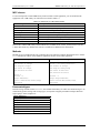
Languages supported by the CYDAS UDR Library, at the time this manual was published, are listed in the
following table. Both 16- and 32-bit versions are supported where applicable.
1
CYDAS UDR Library User’s Guide
Introducing the CYDAS UDR (Universal Driver) Library
Microsoft Windows Languages
Borland Windows Languages
Visual Basic
Visual C/C++
Quick C for Windows
Microsoft C
Borland C++
Borland C++ Builder
Delphi
Microsoft DOS Languages
Borland DOS Languages
QuickBasic 4.5
Professional Basic 7.0
Visual Basic for DOS
Quick C
Turbo C
Turbo C++
Borland C++
Hewlett Packard
(Now Agilent)
HP VEE
.NET Languages
VB .NET
C# .NET
Universal across platforms: The CYDAS UDR Library provides the same sets of functions for DOS,
Windows 3.x and 32-bit Windows (95/98/ME/NT/2000/XP). Additionally, these functions have been
extended to support the .NET environment.
2
2
Installation and Configuration
Installing the CYDAS UDR Library
To install the CYDAS UDR Library, follow the steps below
1.
Place the CYDAS UDR Library CD in your CD drive.
The CyberResearch CD dialog opens.
If the dialog does not open, use Windows Explorer to run the setup.exe on the root of the CD.
2.
From the CyberResearch CD dialog, click on the Install InstaCal and the CYDAS UDR Library button.
3.
Follow the installation instructions as prompted.
4.
Leave the CYDAS UDR Library CD in your CD drive, and restart your computer.
InstaCal is a powerful installation, test, and calibration software package that is installed as part of the
CYDAS UDR Library package. Refer to the Quick Start Guide for examples of using InstaCal with DEMO
BOARD
The CB.CFG file and InstaCal
All board-specific information, including current installed options, are stored in the file CB.CFG which is read
by CYDAS UDR Library. InstaCal creates and/or modifies this file when board configuration information is
added or updated. The CYDAS UDR Library will not function without the CB.CFG file.
For this reason, you must use InstaCal to modify all board setups and configurations as well as to install or
remove boards from your system.
Installation – .NET support
CYDAS UDR Library support for .NET requires that the Microsoft .NET framework already be installed on
the system before you install the CYDAS UDR Library.
Installation – HP VEE support
Before installing HP VEE support, install the CYDAS UDR Library and InstaCal.
After you install the HP VEE application and drivers, run InstaCal and configure the driver. InstaCal is an
installation, calibration, and test program that creates a required configuration file describing the specifics of
the hardware installed.
The changes made to your system when installing HP VEE Support are identical to the changes made when
installing the CYDAS UDR Library, except for the following:
The menu bar program VEE.MNU (or CBI.MNN, depending on the version) is written to the VEE
directory.
3
CYDAS UDR Library User’s Guide
Installation and Configuration
Handling multiple custom menu bars (VEE.MNU)
If you use a custom VEE.MNU, such as the one shipped with DT-VEE, the install program may overwrite it.
Contact technical support (203.483.8815) for information on handling multiple custom menu bars.
Example programs are added to the VEE installation directory. The CYDAS UDR Library sample VEE
programs have a .VEE extension. For a list of sample programs, refer to the "Example Programs" chart in
Chapter 1, "Functional Overview," of the CYDAS UDR Library Function Reference, available on our
website, on this software CD, and C:\MCC\Documents (by default) after software is installed.
Licensing information
Each original copy of CYDAS UDR Library is licensed for development use on one CPU at a time. It is theft
to make copies of this program for simultaneous program development.
Redistributing a custom UDR Library application
The easiest way to distribute an application written with the CYDAS UDR Library is to include a copy of
CyberResearch's InstaCal installation package with the application. Instruct the end user to install InstaCal
before installing the application.
Some developers may want to integrate the installation of the required CYDAS UDR Library drivers into the
custom application's installation. This should only be attempted by developers experienced in installation
development.
Following is an overview of the two methods.
Distributing InstaCal in addition to your custom UDR Library application
If you create an application using the CYDAS UDR Library, you may distribute the necessary runtime files
(CYDAS UDR Library driver files) with the application royalty free. These files can be installed from
CyberResearch's InstaCal installation package. To distribute a custom UDR Library application, provide the
end user with two CDs or disks:
One CD or disk that contains CyberResearch's InstaCal application. InstaCal must be installed before the
custom UDR Library application.
One CD or disk that contains the setup program for their custom VB or C++ application.
You may not distribute any files that give the end user the ability to develop applications using the CYDAS
UDR Library.
Integrating InstaCal into your custom UDR Library installation CD or disk
For developers who wish to distribute their application on one CD, refer to the CYDAS UDR Library
Redistribution Guide. This document contains procedures to merge the setup programs for both InstaCal and
the custom UDR Library application into one setup program that you can distribute on one CD or disk. The
merging process is complicated — only experienced programmers should attempt to do this.
When you install the software, the CYDAS UDR Library Redistribution Guide (ULRedist.pdf) is copied to the
default installation directory "C:\MCC\Documents" on your local drive.
4
3
Getting Started
The CYDAS UDR Library is callable from many languages and environments, including Visual Basic®,
Visual C++, Borland C++ Builder, and Delphi. A list of the languages currently supported by the CYDAS
UDR Library is provided on page 1. Additionally, the UDR Library is now callable from any language
supported by the .NET framework. This chapter describes how to use the library from each of the languages,
as well as several 16-bit environments. The first section of the chapter describes details of the library that
apply to all languages. The following sections describe the differences for each language.
Before starting your application, you should perform the following:
Set up and test your boards with InstaCal. The CYDAS UDR Library will not function until InstaCal has
created a configuration file (CB.CFG).
Run the example programs for the language you program in.
Example programs
Example programs are installed into the Sample32 and Sample16 installation subdirectory for each
programming language mentioned above. Note that 16-bit sample programs are only installed when you
install the 16-bit library. The names of the installation folders are:
C
CWIN
DELPHI
VBWIN
All .NET applications run in the 32-bit Windows environment. A complete set of UDR Library for .NET
example programs are included in the C# and VB.NET folders of the CYDAS UDR Library installation
directory. Each program illustrates the use of CYDAS UDR Library functions from within a .NET program.
For a complete list of example programs, refer to the CYDAS UDR Library Function Reference
The CYDAS UDR Library Function Reference contains tables that list the UDR Library and UDR Library for
.NET example programs. Each table contains the name of the sample program and the functions that the
program demonstrates. This document is available on our website, on this software CD, and
C:\MCC\Documents (by default) after software is installed.
5
4
CYDAS UDR Library Description and Use
The CYDAS UDR Library consists of a set of functions that are callable from your program. These functions
are grouped according to their purpose. All of the groups except for Miscellaneous are based on which type of
device they are used with.
Important - Read the UDR Library documentation, Readme file, and run the example programs
In order to understand the functions, please read the board-specific information section contained in this
manual and in the Readme files supplied on the CYDAS UDR Library disk. We also urge you to examine and
run one or more of the example programs supplied prior to attempting any programming of your own.
Following this advice can save you hours of frustration and wasted time.
General UDR Library language interface description
The interface to all languages is a set of function calls and a set of constants. The list of function calls and
constants are identical for each language. All of the functions and constants are defined in a "header" file for
each language. Refer to the sections below, and especially to the example programs for each language. This
manual is brief with respect to details of language use and syntax. For more detailed information, review the
example programs. Example programs for each language are located in the installation directory.
Function arguments
Each library function takes a list of arguments and most return an error code. Some functions also return data
via their arguments. For example, one of the arguments to cbAIn() is the name of a variable in which the
analog input value will be stored. All function arguments that return data are listed in the "Returns" section of
the function description.
Constants
Many functions take arguments that must be set to one of a small number of choices. These choices are all
given symbolic constant names. For example, cbTIn() takes an argument called Scale that must be set to
CELSIUS, FAHRENHEIT or KELVIN. These constant names are defined, and are assigned a value in the "header"
file for each language. Although it is possible to use the numbers rather than the symbolic constant names, we
strongly recommend that you use the names. Using constant names make your programs more readable and
more compatible with future versions of the library. The numbers may change in future versions, but the
symbolic names always remain the same.
Options arguments
Some library functions have an argument called Options. The Options argument is used to turn on and off
various optional features associated with the function. If you set Options = 0, the function sets all of these
options to the default value, or OFF.
Some options can have an alternative value, such as DTCONNECT and NODTCONNECT. If an option can have
more than one value, one of the values is designated as the default. Individual options can be turned on by
adding them to the Options argument. For example:
Options = BACKGROUND will turn on the "background execution" feature.
Options = BACKGROUND+CONTINUOUS will select both the "background execution" and the "continuous
execution" feature.
6
CYDAS UDR Library User’s Guide
CYDAS UDR Library Description and Use
Error handling
Most library functions return an error code. If no errors occurred during a library call, 0 (or NOERRORS) is
returned as the error code. Otherwise, it is set to one of the codes listed in the CYDAS UDR Library Function
Reference "Error Codes" chapter. This document is available on our website, on this software CD, and
C:\MCC\Documents (by default) after software is installed.
If a non-zero error code is returned, you can use cbGetErrMsg() to convert the error code to a specific error
message. As an alternative to checking the error code after each function call, you can turn on the library's
internal error handling with cbErrHandling().
16-bit values using a signed integer data type
When using functions that require 16-bit values, the data is normally in the range of 0 to 65535. However,
some programming languages, such as BASIC and Visual Basic only provide signed data types. When using
signed integers, reading values above (32767) can be confusing.
The number (32767) in decimal is equivalent to (0111 1111 1111 1111) binary. The next increment (1000
0000 0000 0000) binary has a decimal value of (-32768). The maximum value (1111 1111 1111 1111)
binary translates to (-1) decimal. Keep this in mind if you are using Basic, Visual Basic (up to version 6) or
other languages that don’t support unsigned integers.
There is additional information on this topic in the CYDAS UDR Library Function Reference. This document
is available on our website, on this software CD, and C:\MCC\Documents (by default) after software is
installed. Also, refer to the documentation supplied with your language compiler.
Using the CYDAS UDR Library in Windows
All 32-bit applications (including console applications) access the 32-bit Windows Dynamic Link Library
(DLL) version of the CYDAS UDR Library (CBW32.DLL). Example programs are provided for MS Visual
C++, MS Visual Basic, Borland C++, and Borland Delphi in the Sample32 subdirectories of the installation
directory. These sample programs illustrate the use of CBW32.DLL.
For 16-bit Windows applications, or Windows applications running in Windows 3.x, the 16-bit Windows
DLL version of the CYDAS UDR Library (CBW.DLL) should be used. Example programs are provided for
Visual Basic and both Borland and MS C in the Sample16 subdirectories of the installation directory. These
programs illustrate the use of CBW.DLL.
Due to the differences in memory management among DOS, Windows 3.x, and 32-bit Windows
(95/98/ME/NT/2000/XP), the scan functions have slightly different argument lists. In DOS libraries, all scan
functions take a pointer to a data array as one of their arguments. In Windows 3.x, these functions take a
handle to a Windows Global Memory buffer instead of a pointer to an array. In the 32-bit Windows version,
these functions take a pointer (a 32-bit virtual address) or a handle returned from cbWinBufAlloc().
The affected functions are:
cbAInScan()
cbAOutScan()
cbAPretrig()
cbDInScan()
cbDOutScan()
cbStoreOnInt()
7
CYDAS UDR Library User’s Guide
CYDAS UDR Library Description and Use
The Windows library contains four functions for managing these Windows global memory buffers:
cbWinBufAlloc()
cbWinBufFree()
cbWinArrayToBuf()
cbWinBufToArray()
Real-time acquisition under Windows
Real-time acquisition is available for Windows. To operate at full speed in Windows, the A/D board must
have an onboard FIFO buffer. All of our advanced designs have FIFO buffers, including our CYDAS xP
boards (except for the CYDAS 8P), and many of our ISA boards, such as the CYDAS 80x, CYDAS 160x,
CYDAS 140x, and CYDAS 1802ST. All of these data acquisition boards will operate at full speed in
Windows.
Applying software calibration factors in real time on a per-sample basis eats up machine cycles. If your CPU
is slow, or if processing time is at a premium, withhold calibration until after the acquisition run is complete.
Turning off real-time software calibration saves CPU time during a high speed acquisition run.
Processor speed
Processor speed remains a factor for DMA transfers and for real-time software calibration. Processors of less
than a 150 megahertz (MHz) Pentium class may impose speed limits below the capability of the board (refer
to specific board information.)
If your processor is less than a 150 MHz Pentium and you need an acquisition speed in excess of 200 kilohertz
(kHz), use the NOCALIBRATEDATA option to a turn off real-time software calibration and save CPU time.
After the acquisition is run, calibrate the data with cbACalibrateData().
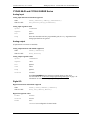
Visual Basic for Windows
To use the CYDAS UDR Library with Visual Basic, include the CYDAS UDR Library declaration file
CBW.BAS in your program. Include the file as a module in the project, or include it by reference inside those
Forms which call into the CYDAS UDR Library. Once the declarations for the CYDAS UDR Library have
been added to your project, call the library functions from any Form's event handlers.
When using the 32-bit version of Visual Basic, CBW.BAS references CBW32.DLL to call CYDAS UDR
Library functions. This is accomplished with conditional compile statements. When using 16-bit versions of
the Visual Basic (such as versions 3.0 or older), these conditional compile statements must be deleted.
For Visual Basic 6.0 and older, Windows memory buffers cannot be mapped onto arrays. As a consequence,
the cbWinArrayToBuf() and cbWinBufToArray() functions must be used to copy data between arrays and
Windows buffers.
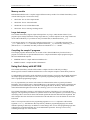
Example:
Count = 100
MemHandle = cbWinBufAlloc (Count)
cbAInScan (......,MemHandle,...)
cbWinBufToArray (MemHandle, DataArray(0), 0, Count)
For i = 0 To Count
Print DataArray(i)
Next i
cbWinBufFree (MemHandle)
8
CYDAS UDR Library User’s Guide
CYDAS UDR Library Description and Use
Visual Basic example programs
A complete set of Visual Basic example programs is included in the VBWIN folder of the CYDAS UDR
Library installation directory. Each program illustrates the use of a CYDAS UDR Library function from
within a Visual Basic program. The .FRM files contain the programs, and the corresponding .VBP or .MAK
files are the project files used to build the programs for Visual Basic.
Microsoft Visual C++
To use the CYDAS UDR Library with MS Visual C++, include the CYDAS UDR Library header file CBW.H
in your C/C++ program and add the library file CBW32.LIB to your library modules for linking to the
CBW32.DLL. When using a 16-bit version of MS Visual C++, replace the library file CBW32.LIB with
CBW.LIB.
Microsoft Visual C++ example programs
The CWIN folder of the CYDAS UDR Library installation directory contains three sample programs Wincai01, Wincai02 and Wincai03. Each program is an example of a simple C program that calls a few of the
CYDAS UDR Library functions from a Windows application. These programs contain directives for building
16- OR 32- bit applications. Use the .MAK project files to build a 16-bit application, and the .DSP project
files to build a 32-bit application.
The non-Windows C examples in the C folder of the installation directory provide a more complete set of
examples. You can compile these programs as 32-bit console applications for Windows by using the
MAKEMC32.BAT file.
Borland C /C++ for Windows
For 32-bit Borland (or Inprise) C/C++ compilers, include the CYDAS UDR Library header file CBW.H in
your program and link with the import library file CBW32BC.LIB.
When using the 16-bit version of Borland C/C++, use a tool called IMPLIB to generate an OMF-style import
library that your application can link with. For 16-bit users, IMPLIB accepts a DLL (CBW.DLL) as input and
creates an OMF-style import library (BCBW.LIB). You can run IMPLIB on CBW.DLL to emit a 16-bit
OMF-style import library (BCBW.LIB).
Borland C/C++ example programs
The non-Windows C examples provide an extensive set of examples. These can be compiled as 32-bit console
applications using the MAKEBC32.BAT file.
Delphi example programs
A complete set of Delphi example programs is included in the DELPHI folder of the CYDAS UDR Library
installation directory. Each program illustrates the use of one CYDAS UDR Library function from within a
Delphi program. The .PAS files contain the programs. The corresponding .DPR file is the Project file used to
build the program in a 16 bit or 32 bit Delphi environment.
In 16-bit Delphi environments, use the cbw.dll header. In 32-bit Delphi environments use the cbw32.dll
header. Conditionals within the example programs determine which of the DLLs is used. Where integers are
passed by reference to a CYDAS UDR Library function, use the SmallInt data type in 32-bit environments.
The relevant functions are defined this way in the 32-bit header, so if you try to pass an Integer data type you
will get a compiler error.
9
CYDAS UDR Library User’s Guide
CYDAS UDR Library Description and Use
Using the Library with DOS BASIC
Each of the supported versions of BASIC consists of two distinct systems. Programs can be loaded into the
BASIC editor and run from within the integrated BASIC environment. Programs can also be compiled by a
command line compiler into stand-alone executable programs that can be run on their own without the help of
the integrated BASIC environment. The CYDAS UDR Library provides the tools for both methods.
BASIC header file
Every BASIC program that uses the CYDAS UDR Library must have a line which includes the BASIC
CYDAS UDR Library header file - CB.BI. The following line should appear near the start of every program,
before the first library call is made.
'$INCLUDE: 'CB.BI'
Using the Library within the integrated BASIC environment
When you start up BASIC, load the "quick library" version of CYDAS UDR Library.
For Quick BASIC, type:
qb /l cbqb
For Professional BASIC, type:
qbx /l cbpb
For VisualBasic for DOS, type:
vbdos /l cbvb
Using the Library with the BASIC command line compiler
To build stand-alone executable files with the command line compiler, you must link your compiled BASIC
program with the stand-alone version of the CYDAS UDR Library. To do this, you must supply the linker
with the library name. The names of the .lib files are:
QuickBasic:
CBQB.LIB
Professional Basic:
CBPB.LIB
VisualBasic for DOS: CBVB.LIB
Sample BASIC programs
The sample BASIC programs demonstrate how to call each function in the CYDAS UDR Library. These
programs can be run from within the integrated BASIC environment. They can also be compiled using the
command line compiler with the batch file supplied. The names of the batch files are:
QuickBasic:
Professional BASIC: MAKEPB.BAT
VisualBasic for DOS: MAKEVB.BAT
MAKEQB.BAT
Passing arguments to the CYDAS UDR Library
All functions in the library require that arguments be passed to them. The file CB.BI contains the definition of
all the argument types that are passed. In general, there are two classes of arguments: inputs and outputs.
10
CYDAS UDR Library User’s Guide
CYDAS UDR Library Description and Use
Input arguments
Input arguments to a library function are listed in the CB.BI file definition as BYVAL. You can pass these
arguments as either a variable or a constant. For example, both of these versions are acceptable:
BoardNum% = 0
cbStopBackground (BoardNum%)
or
cbStopBackground (0)
Output arguments
Output arguments pass information back to the calling function. For example, cbAIn() returns the value from
an A/D to the DataValue% argument. Others arguments are both inputs and outputs. For example, the Rate&
argument specifies the requested sampling rate for cbAInScan() (Input).
The actual sampling rate can vary from the requested sampling rate. cbAInScan() returns the actual rate to the
Rate& argument (output). Output and input/output arguments are defined in the CB.BI function definitions as
SEG. All SEG arguments can only be passed via a variable.
The following example is correct:
Count& = 1000
Rate& = 15000
cbAInScan (0, 0, 1, Count&, Rate&, BIP5VOLTS, DataArray(0), 0)
The following example is NOT correct:
cbAInScan (0, 0, 1, 1000, 15000, BIP5VOLTS, DataArray(0), 0)
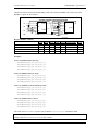
DataArray argument with multiple channels
Some functions have a DataArray argument. DataArray either receives the data from an input function, such
as cbAInScan(), or contains the data to send to an output function, such as cbAOutScan().
DataArray must be dimensioned to be large enough to contain all of the data. The array can either be
dimensioned with one-dimension or two dimensions. When sampling more than one channel, it is often more
straightforward to use a two-dimensional array. The code below shows both methods:
DIM DataBuffer (1999)
elements.
'One-dimensional array. 0 to 1,999 (2,000)
or
DIM DataBuffer (1, 999)
'Two-dimensional array. 0 & 1 with 0-999
(1,000) elements each.
LowChan% = 2
HighChan% = 3
Count& = 2000
Rate& = 1000
cbAInScan (0, LowChan%, HighChan%, Count&, Rate&, BIP5VOLTS, DataBuffer(0), 0)
or
cbAInScan (0, LowChan%, HighChan%, Count&, Rate&, BIP5VOLTS, DataBuffer(0,
0), 0)
11
CYDAS UDR Library User’s Guide
CYDAS UDR Library Description and Use
The advantage of using the two-dimensioned array is that you can directly address the data in the array by
channel. Therefore, in the example above, DataBuffer (0, 99) addresses the 100th sample for channel 2
(channel 2 was the first element in the array; LowChan%).
When running UDR Library for .NET, order Visual Basic arrays as DataArray (sample, chan). The above
example would be written in UDR Library for .NET as DataBuffer (99, 0).
String arguments
cbGetErrMsg() requires that a string variable be passed as an argument. This string variable must have been
previously allocated to be large enough to hold the longest error message. To do this, use Quick BASIC's
space$ function as it is done in the example program.
ErrStr$ = space$ (ERRSTRLEN)
Integer arguments
BASIC does not support unsigned integers (0 to 65,535). Values for the integer data type range from
–32,768 to 32,767. When using functions that require unsigned integers, the data must be converted. (Refer to
"16-bit values using a signed integer data type" on page 7 for information on 16-bit values using unsigned
integers.)
BACKGROUND operation
If you use the BACKGROUND option with any function, you must declare the associated data array as '$STATIC.
Unless you declare an array as '$STATIC, BASIC may move the array around in memory as the program is
executing. Whenever you use the BACKGROUND option, the I/O function reads/writes from the data array in the
background while the BASIC program continues executing in the "foreground.” If BASIC moves the array
while the I/O function is reading/writing to it, it will cause intermittent and unpredictable problems.
cbStopBackground() should be executed after normal termination of all background functions to clear
variables and flags.
Using the Library with VisualBasic® for DOS
Compiling stand-alone EXE files
Due to a quirk in VisualBasic for DOS, the following message displays if you compile a stand-alone EXE file
from within the IDE and set the EXE type to "Stand alone EXE file":
"fixup overflow at 334 in the segment -TEXT target external 'B$CEND'".
Disregard this error message. The compiled program will run without error.
Using the Library with C for DOS
The C libraries included with the system can be used with either the Microsoft or Borland C compilers.
C header file
Every C program that uses the CYDAS UDR Library must have a line which includes the CYDAS UDR
Library C header file, CB.H. The following line should appear near the start of every program, before the first
library call is made.
#include "cb.h"
12
CYDAS UDR Library User’s Guide
CYDAS UDR Library Description and Use
Memory models
Both Borland and Microsoft C compilers support different memory models. The CYDAS UDR Library comes
with the following four versions of the library.
CBCC.LIB - For use with compact model
CBCS.LIB - For use with small model
CBCM.LIB - For use with medium model
CBCL.LIB - For use with large and huge model
Large data arrays
The CYDAS UDR Library supports input and output from very large (>64K) amounts of data. If your
program requires storage and transfer of large single data sets, you must compile it for the "huge" model and
use the CBCL.LIB library. If you declare an array to hold the data, it should be declared __huge.
If you allocate memory (as is done in the example programs using malloc) it should be allocated using
_halloc (Microsoft) or halloc (Borland), the pointer declared as __huge and memory freed using _hfree
(Microsoft) or hfree (Borland). Note that you must also include the malloc.h header.
Compiling the sample C programs
The example programs demonstrate how to call each of the CYDAS UDR Library functions from a C
program. Two batch files are provided that show how to compile and link the sample programs using the
Microsoft and Borland compilers.
MAKEMC16.BAT - compile and link with Microsoft C
MAKETC16.BAT - compile and link with Borland C
Using the Library with HP VEE
The CYDAS UDR Library with HP VEE includes a complete interface to HP VEE providing a
DataAcq-specific menu bar addition and functions as well as complete examples of all the library functions.
To understand how the interface to HP VEE interacts with I/O boards, you need to study both this manual and
the example programs. This manual is written for symbolic programming languages such as BASIC and C.
VEE is a graphical programming language.
It is very important that you scan the entire manual for information that relates to general performance.
Remember, VEE is using the entire CYDAS UDR Library as the interface to the I/O boards. Limitations and
performance factors in the library are reflected in VEE programs that use the library. The manual contains
related information throughout the contents. We encourage you to review the entire manual.
The CYDAS UDR Library interface to VEE follows the structure of the library as it is used with all other
languages. The arguments presented here in symbolic format are the same arguments you will need to specify
when using VEE to control an I/O board. The manual explains the functions and each of the arguments. The
VEE examples show how the function is interfaced to VEE and show how to use the function to control the
I/O boards.
There is one exception to this rule: the programming argument MemHandle is replaced in VEE with the
argument DataArray. VEE allocates data arrays directly. Windows programming languages use another
method of pointing to data arrays. In addition to a name change, there is some VEE programming logic done
to dimension a two-dimensional data array for all multichannel operations. This logic can be seen by
examining the design view of the function.
13
CYDAS UDR Library User’s Guide
CYDAS UDR Library Description and Use
Each function is implemented as a panel. All the arguments are accessible on the panel and require a value. In
the example programs and in simple projects this method of presenting the functions is easiest to use. Each
value is hard-coded into the panel.
If more complex projects are undertaken, open the design view of the function and drag certain arguments
outside the panel. Dragging an object outside the panel will create a 'pin' to which you can connect constants,
variables, or objects such as slider bars. In large projects the ability to supply an argument with a variable that
acquires its value elsewhere is especially useful. See the VEE manual for information on how to do this.
See the example program ULAI06.VEE for an example of the multiple uses of several arguments, where it is
better to specify the argument values globally. In this example, we have brought several arguments out of the
panel.
Remember, if you drag an argument outside a panel you must reconnect the program flow (top and bottom
pins) of the remaining arguments; the one above to the one below the argument you removed.
New HP VEE functions
Several new functions have been added strictly for use with HP VEE. These functions are listed separately in
a section devoted to the VEE-specific functions. All VEE-specific functions begin with the name cbv, rather
than cb. The new functions add VEE style data and array handling to the library.
Using the HP VEE interface is simple, and is a great way to connect your VEE programs to the real world.
Read the manual, start with the examples, and then begin working up your own projects. Remember to call us
with suggestions!
Installation note
Install the CYDAS UDR Library in the default directory. The HP VEE library import block CBI_UL contains
an exact path specification for the library CBV.DLL and its header file CBV.H. If you do not install these files
into the default directory suggested by the install program, you will have to edit the library import block
CBI_UL to point to the directory where the files are installed.
To edit the library import block CBI_UDR:
1.
Click on the DataAcq menu item and then click on its cbLibrary sub-menu item.
2.
Place the mouse cursor at the desired location for the library import block and press the left mouse button
once.
3.
Double-click on the library import block object. A detailed CBI_UL library block will be displayed.
4.
Within the CBI_UL library block, click on the button to the right of File Name, then enter the new path
with the file name and click OK.
5.
Click on the button to the right of Definition File, then enter the new path with the file name and click
OK.
Using VEE 3.2 or later
If you are using VEE 3.2 or later, edit the library import block and change the library name from CBV.DLL to
CBV32.DLL. Be sure to include the proper path.
14
5
CYDAS UDR Library for .NET Description & Use
Programming the CYDAS UDR Library API is now available through the various languages supported by the
Microsoft .NET framework. All .NET applications access the 32-bit Windows CYDAS UDR Library
(CBW32.DLL) through the MccDaq .NET assembly (MCCDAQ.DLL). The MccDaq assembly provides an
interface that exposes each CYDAS UDR Library function that is callable from the .NET language.
The CYDAS UDR Library for .NET is designed to provide the same "look and feel" as the CYDAS UDR
Library for 32-bit Windows. This design makes it easier to port over existing data acquisition programs, and
minimizes the learning curve for programmers familiar with the CBW32.DLL interface.
In the CYDAS UDR Library for .NET, each function is exposed as a class method with virtually the same
parameter set as their UDR Library counterparts.
Configuring a UDR Library for .NET project
In a .NET application, there are no header files to include in your project. You define methods and constants
by adding the MccDaq assembly, or Namespace, as a reference to your project. You access UDR Library for
.NET methods through a class that has the CYDAS UDR Library as a member.
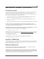
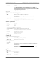
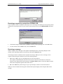
To add the MccDaq Namespace as a reference in a Visual Studio .NET project:
1.
Start a new Visual Basic or C# project in Visual Studio .NET.
2.
From the Visual Studio .NET Solution Explorer window, right-click on References and select Add
Reference.
The Add Reference window appears.
3.
From the .NET tab, select the MccDaq option from the displayed list of .NET assemblies and click on the
Select button.
MccDaq displays in the Selected Components area on the window.
15
CYDAS UDR Library User’s Guide
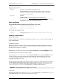
4.
CYDAS UDR Library for .NET Description & Use
Click on the OK button.
MccDaq appears under the References folder in the Solution Explorer window.
The MccDaq Namespace is now referenced by your Visual Studio .NET project.
General UDR Library for .NET language interface description
The MccDaq Namespace provides an interface that exposes each CYDAS UDR Library for .NET method as
a member of a class with virtually the same parameters set as their UDR Library counterparts. The MccDaq
Namespace is a logical naming scheme for grouping related types. The .NET Framework uses a hierarchical
naming scheme for grouping types into logical categories of related functionality.
When you develop a .NET application that uses the CYDAS UDR Library, you add the MccDaq Namespace
as a reference to your project. There are no "header" files in a .NET project.
The MccDaq Namespace contains the classes and enumerated values by which UDR Library for .NET
applications access the CYDAS UDR Library data types and functions.
The MccDaq Namespace contains four main classes:
MccBoard class
ErrorInfo class
MccService class
GlobalConfig class
The MccDaq assembly allows you to design Common Language Specification (CLS)-compliant programs. A
CLS-compliant program contains methods that can be called from any existing or future language developed
for the Microsoft .NET framework. Use CLS-compliant data types to ensure future compatibility.
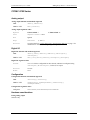
MccBoard class
The MccBoard class provides access to all of the methods for data acquisition and properties providing board
information and configuration for a particular board.
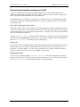
Class Constructors
The MccBoard class provides two constructors; one which accepts a board number argument and one with no
arguments.
The following code examples demonstrate how to create a new instance of the MccBoard class using the latter
version with a default board number of 0:
Visual Basic
C#
Private DaqBoard As MccDaq.MccBoard
DaqBoard = New MccDaq.MccBoard()
private MccDaq.MccBoard DaqBoard;
DaqBoard = new MccDaq.MccBoard();
16
CYDAS UDR Library User’s Guide
CYDAS UDR Library for .NET Description & Use
The following code examples demonstrate how to create a new instance of the MccBoard class with the board
number passed to it:
Visual Basic
C#
Private DaqBoard As MccDaq.MccBoard
DaqBoard = New MccDaq.MccBoard(BoardNumber)
private MccDaq.MccBoard DaqBoard;
DaqBoard = new MccDaq.MccBoard(BoardNumber);
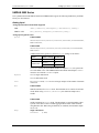
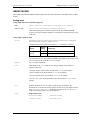
Class properties
The MccBoard class also contains six properties that you can use to examine or change the configuration of
your board. The configuration information for all boards is stored in the CB.CFG file, and is loaded from
CB.CFG by all programs that use the library.
Properties
Description
BoardName
BoardNum
BoardConfig
Name of the board associated with an instance of the MccBoard class.
Number of the board associated with an instance of the MccBoard class.
Gets a reference to a cBoardConfig class object. Use this class reference to get or set
various board settings.
Gets a reference to a cCtrConfig class object. Use this class reference to get or set various
counter settings.
Gets a reference to a cDioConfig class object. Use this class reference to get or set various
digital I/O settings.
Gets a reference to a cExpansionConfig class object. Use this class reference to get or set
various expansion board settings.
CtrConfig
DioConfig
ExpansionConfig
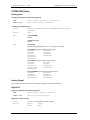
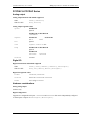
Class methods
The MccBoard class contains close to 80 methods that are equivalents of the function calls used in the standard
CYDAS UDR Library. The MccBoard class methods have virtually the same parameters set as their UDR
Library counterparts.
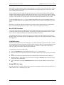
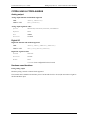
The following code examples demonstrate how to call the AIn()method of the MccBoard object MccDaq:
Visual Basic
ULStat = DaqBoard.AIn(Chan, Range, DataValue)
C#
ULStat = DaqBoard.AIn(Chan, Range, out DataValue);
Many of the arguments are MccDaq enumerated values. Enumerated values take settings such as range types
or scan options and put them into logical groups. For example, to set a range value, reference a value from the
MCCDaq.Range enumerated type, such as Range.Bip5Volts. Refer to Table 5-1 on page 18 for a list of
MccDaq enumerated values.
The CYDAS UDR Library Function Reference contains detailed information about all MccBoard class
methods. This document is available on our website, on this software CD, and C:\MCC\Documents (by
default) after software is installed.
ErrorInfo class
Most UDR Library methods return ErrorInfo objects. These objects contain two properties that provide
information on the status of the method called:
ErrorInfo.Message property gets the text of the error message associated with a specific error code.
ErrorInfo.Value property gets the named constant value associated with the ErrorInfo object.
The ErrorInfo class also includes error code enumerated values, which define the error number and
associated message which can be returned when you call a method.
17
CYDAS UDR Library User’s Guide
CYDAS UDR Library for .NET Description & Use
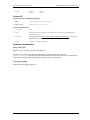
MccService class
The MccService class contains all members for calling utility UDR Library functions. This class contains
nine static methods (you do not need to create an instance of the MccService class to call these methods):
DeclareRevision()
WinArrayToBuf()
ErrHandling()
WinBufToArray()
GetRevision()
WinBufAlloc()
FileGetInfo()
WinBufFree()
FileRead()
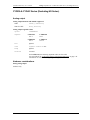
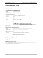
The following code examples demonstrate how to call a UDR Library for .NET memory management method
from within a CYDAS UDR Library program:
WindowHandle=MccService.WinBuffAlloc(1000)
MccService.WinBuffFree(WindowHandle)
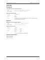
GlobalConfig class
The GlobalConfig class contains all of the members for getting global configuration information. This class
contains three properties:
MccDaq.GlobalConfig.NumBoards property returns the maximum number of boards that you can install
at one time. ConfigGlobal=MccDaq.GlobalConfig.NumBoards
MccDaq.GlobalConfig.NumExpBoards property returns the maximum number of expansions boards that
are allowed to be installed on the board. ConfigGlobal=MccDaq.GlobalConfig.NumExpBoards
MccDaq.GlobalConfig.Version property is used to determine compatibility with the library version.
ConfigGlobal=MccDaq.GlobalConfig.Version
Each of these properties is typed as an Integer.
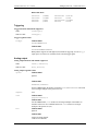
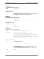
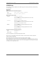
MccDaq enumerations
The MccDaq Namespace contains enumerated values which are used by many of the methods available from
the MccDaq classes (see Table 5-1). Refer to specific method descriptions in the CYDAS UDR Library
Function Reference for the values of each enumerated type. This document is available on our website, on this
software CD, and C:\MCC\Documents (by default) after software is installed.
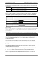
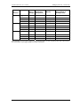
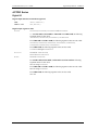
Table 5-1. MccDaq Enumerated Values
Enumeration Name
Description
MccDaq.BCDMode
MccDaq.C8254Mode
MccDaq.CompareValue
MccDaq.ConnectionPin
Lists all of the counting format options.
Lists all of the operating modes for 8254 counters.
List all options for comparing values while configuring a 9513 counter.
Defines the connector pins to associate with the signal type and direction when
calling the SelectSignal() method.
Defines the possible state of each counter channel (enabled/disabled).
MccDaq.CounterControl
18
CYDAS UDR Library User’s Guide
CYDAS UDR Library for .NET Description & Use
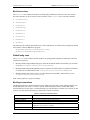
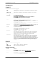
Enumeration Name
Description
MccDaq.CountDirection
MccDaq.CountEdge
MccDaq.CounterRegister
MccDaq.CounterSource
MccDaq.CountingMode
MccDaq.CtrlOutput
MccDaq.DACUpdate
MccDaq.DataEncoding
MccDaq.DigitalPortDirection
MccDaq.DigitalLogicState
MccDaq.DigitalPortType
MccDaq.DTMode
MccDaq.ErrorHandling
MccDaq.ErrorReporting
MccDaq.EventType
MccDaq.FlagPins
Defines the count direction when configuring counters.
Defines the edge used for counting.
Lists all of the register names to load the count to.
Lists all counter input sources.
Lists all valid modes for a C7266 counter configuration.
Lists all of the options for linking counter 1 to counter 2.
Defines the available DAC update modes
Lists the format of the data that is returned by a counter.
Configures a digital I/O port as input or output.
Defines all digital logic states.
Defines all digital port types.
Lists all modes to transfer to/from the memory boards.
Defines all error handling options.
Defines all error reporting options.
Lists all available event conditions.
Lists all signals types that can be routed to the FLG1 and FLG2 pins on the 7266
counters.
List all valid function types used with data acquisition methods.
List all of the gating modes for configuring a 9513 counter.
List the actions to be taken when the Index signal is received by a 7266 counter.
Lists all configuration information to be used with the MccBoard class
configuration methods.
Enables or disables various options.
List all of the types of output from a 9513 counters.
Lists all of the types of output from an 8536 counters.
Lists all of the resolution multipliers for quadrature input.
Defines the set of ranges within the UDR Library for A/D and D/A operations.
Lists the recycle mode options for 9513 and 8536 counters.
Lists the options for reloading the 9513 counter.
List the available options for paced input/output methods.
List all signal types associated with a connector pin on boards supporting ATCC.
Lists all of the directions available from a specified signal type assigned to a
connector pin.
List all available polarities for a specified signal.
List all of the signal sources of the signal from which the frequency will be
calculated.
List all status bits available when reading counter status.
Lists valid temperature scales that the input can be converted to.
List all time of day options for initializing a 9513 counter.
List all valid trigger types for the MccBoard.SetTrigger method.
Specifies whether or not to apply smoothing to temperature readings.
MccDaq.FunctionType
MccDaq.GateControl
MccDaq.IndexMode
MccDaq.InfoType
MccDaq.OptionState
MccDaq.C9513OutputControl
MccDaq.C8536OutputControl
MccDaq.Quadrature
MccDaq.Range
MccDaq.RecycleMode
MccDaq.Reload
MccDaq.ScanOptions
MccDaq.SignalType
MccDaq.SignalDirection
MccDaq.SignalPolarity
MccDaq.SignalSource
MccDaq.StatusBits
MccDaq.TempScale
MccDaq.TimeOfDay
MccDaq.TriggerType
MccDaq.ThermocoupleOptions
19
CYDAS UDR Library User’s Guide
CYDAS UDR Library for .NET Description & Use
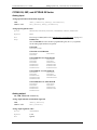
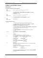
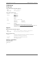
Parameter data types
Many of the CYDAS UDR Library for .NET methods are overloaded to provide for signed or unsigned data
types as parameters. The AConvertData() method is shown below using both signed and unsigned data
types.
VB.NET
Public Function AConvertData(ByVal numPoints As Integer, ByRef adData As
Short, ByRef chanTags As Short) As MccDaq.ErrorInfo
Member of MccDaq.MccBoard
Public Function AConvertData(ByVal numPoints As Integer, ByRef adData As
System.UInt16, ByRef chanTags As System.UInt16) As MccDaq.ErrorInfo
Member of MccDaq.MccBoard
C#
.NET
public MccDaq.ErrorInfo AConvertData (System.Int32 numPoints, System.Int16
adData, System.Int16 chanTags)
Member of MccDaq.MccBoard
public MccDaq.ErrorInfo AConvertData (System.Int32 numPoints, System.UInt16
adData, System.UInt16 chanTags)
Member of MccDaq.MccBoard
For most data acquisition applications, unsigned data values are easier to manage. However, since Visual
Basic (version 6 and earlier) does not support unsigned data types, it may be easier to port these programs to
.NET if the signed data types are used for the method parameters. For additional information on using signed
data types, refer to the section “16-bit values using a signed integer data type” on page 7.
The short (Int16) data type is Common Language Specification (CLS) compliant, is supported in VB, and will
be included in any future .NET language developed for the .NET framework. Using CLS-compliant data types
ensures future compatibility. Unsigned data types are not CLS compliant, but are still supported by various
.NET languages, such as C#.
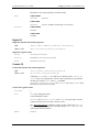
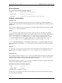
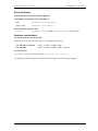
Differences between the UDR Library and UDR Library for .NET
Table 5-2 lists the differences between the CYDAS UDR Library and the CYDAS UDR Library for .NET.
Table 5-2. Differences between UDR Library and UDR Library for .NET
Board
Number
Functions
Constants
Return
value
CYDAS UDR Library
CYDAS UDR Library for .NET
The board number is included
as a parameter to the board
functions.
Set of function calls defined
in a header.
An MccBoard class is created for each board installed, and the
board number is passed to that board class.
Constants are defined and
assigned a value in the
"header" file.
The return value is an Error
code.
Set of methods. Methods of MccBoard or MccService classes. To
access a method, instantiate a UDR Library for .NET class and call
the appropriate method using that class.
Constants are defined as enumerated types.
The return value is an ErrorInfo object that contains the error's
number and message.
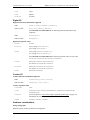
Board number
In a .NET application, multiple boards may be programmed by creating an MccBoard Class object for each
board installed:
Board0 = new MccBoard(0)
Board1 = new MccBoard(1)
Board2 = new MccBoard(2)
Note that the board number may be passed into the MccBoard class, which eliminates the need to include the
board number as a parameter to the board methods.
20
CYDAS UDR Library User’s Guide
CYDAS UDR Library for .NET Description & Use
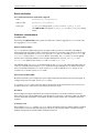
MCC classes
To use board-specific CYDAS UDR Library functions inside a .NET application, you use methods of the
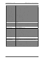
appropriate class. UDR Library for .NET classes are listed in Table 5-3.
Table 5-3. UDR Library for .NET Board Classes
UDR Library for .NET Class
Description
MccBoard
ErrorInfo
BoardConfig
CtrConfig
DioConfig
ExpansionConfig
GlobalConfig
MccService
Access board-related CYDAS UDR Library functions.
Utility class for storing and reporting error codes and messages.
Gets and sets board configuration settings.
Gets and sets counter board configuration settings.
Gets and sets digital I/O configuration settings.
Gets and sets expansion board configuration settings.
Gets and sets global configuration settings.
Access utility CYDAS UDR Library functions.
Refer to the CYDAS UDR Library Function Reference (available on our website, on this software CD, and
C:\MCC\Documents (by default) after software is installed.) for additional class information.
Methods
Methods are accessed through the class containing them. The following example demonstrates how to call the
AIn() method from within a 32-bit Windows application and also from a .NET application.
VB Application using CBW32.DLL
VB .NET Application using MCCDAQ.DLL
Dim
Dim
Dim
Dim
Dim
Dim Board0 As MccBoard
Board0 = new MccDaq.MccBoard(0)
Dim Channel As Integer
Dim Range As MccDaq.Range
Dim ULStat As ErrorInfo
Dim DataValue As UInt16
Board As Integer
Channel As Integer
Range As Integer
ULStat As Integer
DataValue As Short
Board =0
Channel = 0
Range =BIP5VOLTS;
ULStat =cbAIn(Board, Channel, Range,
DataValue)
Channel = 0
Range =Range.BIP5VOLTS;
ULStat =Board0.AIn(Channel, Range,
DataValue)
Enumerated types
Instead of using constants such as BIP5VOLTS, the CYDAS UDR Library for .NET uses enumerated types. An
enumerated type takes settings such as range types, scan options or digital port numbers and puts them into
logical groups. Some examples are:
Range.Bip5Volts
Range.Bip10Volts
Range.Uni5Volts
Range.Uni10Volts
ScanOptions.Background
ScanOptions.Continuous
ScanOptions.BurstMode
21
CYDAS UDR Library User’s Guide
CYDAS UDR Library for .NET Description & Use
If you are programming inside of Visual Studio .NET, the types that are available for a particular enumerated
value display automatically when you type code:
Error handling
For .NET applications, the return value for the CYDAS UDR Library functions is an object (ErrorInfo), rather
than a single integer value. The ErrorInfo object contains both the numeric value for the error that occurred, as
well as the associated error message. Within a .NET application, error checking may be performed as follows:
ULStat=Board0.AIn(Channel, Range, DataValue)
‘check the numeric value of ULStat
If Not ULStat.Value = ErrorInfo.ErrorCode.NoErrors Then
‘if there was an error, then display the error message
MsgBox ULStat.Message
EndIf
Service methods
You can access other CYDAS UDR Library functions that are not board-specific through the MccService
class. This class contains a set of static methods you can access directly, without having to instantiate an
MccService object. The following examples demonstrate library calls to .NET memory management methods:
WindowHandle = MccService.WinBuffAlloc(1000)
MccService.WinBuffFree(WindowHandle)
Configuration methods
In 32-bit Windows applications, you access board configuration information by calling the cbGetConfig and
cbSetConfig API functions. In .NET applications, you access board configuration information through
separate classes, such as cBoardConfig, cCtrConfig, cDioConfig, and cExpansionConfig. Each
configuration item has a separate get and set method.
Some examples of how to access board configuration within a .NET application are shown below:
UlStat = Board0.BoardConfig.GetRange(RangeValue)
UlStat = Board1.DioConfig.GetNumBits(DevNumber, Number)
UlStat = Board2.CtrConfig.GetCtrType(DevNumber, CounterType)
UlStat = Board3.BoardConfig.SetClock(ClockSource)
UlStat = Board4.ExpansionConfig.SetCJCChan(DevNumber, CjcChan)
22
6
How to Use the "Streamer" File Functions
File functions overview
The CYDAS UDR Library can collect very large amounts of data to a "streamer" file. Once all of the data is
streamed to a file, your program reads it back into arrays and processes it in chunks. This feature is
particularly useful when you are using the CYDAS UDR Library from DOS, where memory is limited. The
library contains four functions that are used with "streamer" files:
cbFileAInScan() and cbFilePretrig() read the A/D and store the data in a "streamer" file. The
equivalent UDR Library for .Net methods are FileAInScan() and FilePretrig().
cbFileGetInfo()returns information about the streamer file (the equivalent UDR Library for .Net
method is FileGetInfo().)
cbFileRead() reads data from a "streamer" file to an array (the equivalent UDR Library for .Net method
is FileRead().)
In addition to these library functions, the library comes with three utility programs for use with the
16-bit version of the library; MAKESTRM.EXE, FRAGTEST.EXE and RDSTREAM.EXE. These utilities
are not compatible with the 32-bit version of the library.
MAKESTRM creates a "streamer" file. When using the 16 bit library, this program should be run to allocate a
file large enough to hold all of the data that will be later collected with cbFileAInScan() or
cbFilePretrig() / FileAInScan() or FilePretrig(). The syntax is:
C:\MAKESTRM filename # <enter>
FRAGTEST checks an existing disk file to see if it is fragmented. In order to run at the faster sampling rates,
the "streamer" file must not be fragmented. Refer to "Speeding up Disk Files (De-fragmenting)" on page 24
for more information. The syntax is:
C:\FRAGTEST filename <enter>
RDSTREAM reads a "streamer" file and prints its contents on the screen. The syntax is:
C:\RDSTREAM filename <enter>
Hard disk vs. RAM disk files
The simplest type of file to use is a standard DOS file on a hard disk. Hard disk files have the disadvantage of
being slower than RAM disks. RAM disk (or virtual disk) files are faster but they are limited in size by the
amount of available memory in your computer.
Maximum sampling speed
The maximum sustainable sampling rate that can be specified with the cbFile functions is very hard to
predict. It depends on the speed of the CPU and the speed of the disk.
In addition to the variation in sampling speed from machine to machine, there can also be variations on the
same machine between consecutive operations of the same program. When reading an A/D to memory (nonstreaming modes) there is a hard and fast maximum sampling speed that cannot be exceeded. When using the
streaming modes the maximum rate is much fuzzier and must be arrived at by trial and error.
23
CYDAS UDR Library User’s Guide
How to Use the "Streamer" File Functions
A rough guideline of attainable speeds are those on a 33 MHz 80386 machine with a fast hard disk it should
be possible to collect a megabyte of data at 200 kHz sampling rate to a disk file. It should also be possible to
collect a megabyte of data to a RAM disk at 330 kHz. In general the maximum sustainable speed for
cbFilePretrig() / FilePretrig() will be somewhat less than for cbFileAInScan()/FileAInScan().
Another characteristic of these "streaming" modes is that the more data you collect the lower the maximum
speed will be. On any machine with any speed disk, you can collect 32000 samples to a disk file at the
maximum A/D speed of 330 kHz. If you are pushing the upper limits of speed you will find that you can
collect 100K samples at a faster rate than you can collect 500K samples, etc.
How to determine the maximum sampling speed
The only way to determine the maximum safe speed is to run it repeatedly. The speed may work the first time
but may not necessarily work the next time. The only way to be sure that you can reliably run at a particular
speed is to try it numerous times. Another method is to increase the speed to the point where it begins to fail
every time so that you get some sense of whether or not you are pushing the speed limit on your computer.
To test it, write a program that calls cbFileAInScan() or cbFilePretrig() / FileAInScan() or
FilePretrig() (depending on whether you need pre-trigger data). Check the returned error code. If you get
an OVERRUN error (error code of 29), the sampling rate is too high. Whenever you get OVERRUN error, some data
was collected but not all of it. It is often useful to check how much data was collected to find out whether it
was almost fast enough or not even close.
Speeding up disk files (defragmenting)
Because of the way that disks work, the time that it takes to write to them can vary tremendously. A large disk
file is made up of many small pieces that are written individually to the disk. If the file is contiguous (each
piece is side by side) the speed is very fast. If the file is fragmented (pieces are in different places on the disk)
the speed is much slower. If you create a large disk file, it will most likely be fragmented to some degree, and
the maximum sampling speed will be much lower than it would be for an unfragmented file.
To get around this problem, you should use a disk optimizer or defragmenter program immediately before
creating the streamer file with MAKESTRM. After you create the streamer file, it will remain unfragmented
so long as you do not erase and recreate it. The disk optimizer program included with Norton Utilities™, is
called Speed Disk, or SD. To run it type:
SD /Q
This will execute the "Quick" optimize, which works as well as the full optimization.
After de-fragmenting the disk, create a streamer file that is large enough to hold as much data as you plan to
collect with cbFileAInScan() or cbFilePretrig(). To create the disk file, run the standalone
MAKESTRM.EXE program. This will create a streamer file of the required size.
After the file is created, run FRAGTEST.EXE to see whether or not the file is fragmented. It is possible that
the file may be fragmented even though you just de-fragmented the disk. This is because the disk may contain
some bad sectors that could not be moved when the disk was optimized. When you create the new file and it
hits one of these bad sectors, it has to skip over it, hence fragmentized.
If FRAGTEST reports that the file is fragmented, create a second file and test that with FRAGTEST. Repeat
this until FRAGTEST reports that the file is OK. After you have an unfragmented disk file you can try using it
with cbFileAInScan() or cbFilePretrig() / FileAInScan() or FilePretrig() to collect data. If the
maximum sampling speed is still too slow, you should probably switch to a RAM disk.
24
CYDAS UDR Library User’s Guide
How to Use the "Streamer" File Functions
RAM disks
A RAM disk is not really a disk. It is a device driver that sets aside some of the computer's memory and
makes it appear to DOS as a disk drive. When you install a RAM disk on your computer, it appears exactly as
if you have another VERY fast hard disk drive. For example, if you have one hard disk (drive C:) then when
you install the RAM disk it will appear as if you have another hard disk, drive D.
After the RAM disk is installed, all DOS commands work exactly the same on the RAM disk as on the hard
disk. For example you can COPY, DEL, MKDIR, CD just as you would on a hard disk.
Installing a RAM disk
The RAM disk driver comes with DOS. Refer to your DOS manual for more information. In older versions of
DOS it is called either RAMDRIVE.SYS or VDISK.SYS. To install it you must add one line to your
\CONFIG.SYS file. Find which directory the DOS files are installed in on your machine. CD to that directory
and look for a file called RAMDRIVE.SYS or VDISK.SYS. If it is not there look at the other .SYS files in the
directory and refer to your DOS manual to find out if any of them are a RAM Disk driver. After you have
located the file add an entry to the \CONFIG.SYS file.
If the RAMDRIVE.SYS file was in a directory called DOS then you would add the following line to the
\CONFIG.SYS file.
device=c:\dos\ramdrive.sys
The default size for the RAM disk is usually 64K. You will almost certainly want to make it larger than that.
The larger you make it the more data you can collect but the less memory will be available for other
programs.
To set up a 4 megabyte RAM disk, add the following line to your CONFIG.SYS file:
device=c:\dos\ramdrive.sys 4000
If your computer is an 80x86, install the RAM disk in extended memory (above 1M) by specifying the /e
option:
device=c:\dos\ramdrive.sys 4000 /e
After you add the new line to the \CONFIG.SYS file, reboot the computer (Press CTRL-ALT-DEL) to install the
RAM disk. When the machine reboots it should print a message on the screen that describes the RAM disk.
Using the RAM disk
To use the RAM disk, specify the drive letter in the FileName argument of cbFileAInScan() or
cbFilePretrig()/FileAInScan() or FilePretrig(). For example, if the RAM disk is drive D: on your
system, you could set the name of the "streamer" file in your program to "D:TEST.DAT"
This file can be created with the MAKESTRM.EXE program supplied with the CYDAS UDR Library. To set
up a file large enough to hold a million samples, include the following line in your AUTOEXEC.BAT file:
C:\CB\MAKESTRM D:\TEST.DAT 1000000
The name TEST.DAT is an example. Use the name of your preference. When you execute cbFileAInScan() or
cbFilePreTrig()/FileAInScan() or FilePreTrig(), it will fill up the file on your RAM drive. This file
will be lost as soon as the power is switched off, so if you wish to keep the data you must copy it to the hard
disk before turning the computer off.
25
7
Analog Input Boards
Introduction
All boards that have analog input support the cbAIn()/AIn() and cbAInScan()/AInScan() functions, except
expansion boards, which only support cbAIn(). Boards released after the printing of this manual are described
in Readme files contained on the CYDAS UDR Library disk.
When hardware-paced A/D conversion is not supported, cbAInScan()/AInScan() loops through software
paced conversions. The scan will execute at the maximum speed possible. This speed will vary with CPU
speed. The only valid option in this case is CONVERTDATA.
Concurrent analog input and output for paced analog inputs, paced analog outputs
For boards with both paced analog inputs and paced analog outputs, concurrent analog input and output scans
are supported. That is, these boards allow operations with analog input functions (cbAInScan/AInScan() and
cbAPretrig/APretrig) and analog output functions (cbAOutScan/AOutScan()) to overlap without having to
call cbStopBackground()/StopBackground() between the start of input and output scans.
Trigger support
Digital Trigger
If trigger support is "Polled gate" (as opposed to "Hardware"), you implement a trigger by gating the on-board
pacer. This disables the on-board pacer. The trigger input is then polled continuously until the trigger occurs.
When that happens, the software disables the gate input so that when the trigger returns to its original state, it
does not affect the pacer and acquisition continues until the requested number of samples has been acquired.
There are two side effects to this type of trigger:
The polling portion of the function does not occur in the background, even if the BACKGROUND option was
specified (although the actual data acquisition does).
The trigger does not necessarily occur on the rising edge. Acquisition can start at any time after the
function is called if the trigger input is at "active" level. For this reason, it is best to use a trigger that goes
active for a much shorter time than it is inactive.
Similar to ‘Polled gate’ triggering is ‘Polled digital input’ triggering, where the pacer is disabled while the
state of a digital input is polled. When the state changes to active, the pacer is enabled by the software. The
polled digital input trigger type limitations are very similar to the polled gate type explained above.
Analog Trigger
You set up the trigger levels for an analog trigger using the function cbSetTrigger / SetTrigger, passing the
appropriate values to the HighThreshold and LowThreshold arguments.
For most boards that support analog triggering, you can calculate the HighThreshold and LowThreshold
values by passing the required trigger voltage level and the appropriate Range to the
cbFromEngUnits/FromEngUnits function.
However, for some boards, you must manually calculate HighThreshold and LowThreshold. If a board
requires manual calculation, that information will be included in the Trigger information for the specific
product in this section. The procedure for manually calculating these values is detailed in the CYDAS UDR
Library Function Reference in the description of the cbSetTrigger / SetTrigger function.
26
CYDAS UDR Library User’s Guide
Analog Input Boards
Sampling rate using SINGLEIO
When using this mode of data transfer, the maximum analog sampling rate is dependent on the speed of the
computer in which the board is installed. In general, it is in the range of 5 to 50 kHz. If the requested speed
cannot be sustained, an overrun error will occur. Data will be returned, but likely there will be gaps. Some
boards, such as the CYDAS 08, support only this mode, so the maximum rate attainable with these boards is
system-dependent.
27
CYDAS UDR Library User’s Guide
Analog Input Boards - CYDAS 4020
CYDAS 4020
Analog Input
Analog input functions and methods supported
UDR:
cbAIn(), cbAInScan(), cbATrig(), cbAPretrig(), cbFileAInScan(),
cbFilePretrig()
UDR for .NET:
AIn(), AInScan(), ATrig(), APretrig(), FileAInScan(), FilePretrig()
Analog input argument values
Options
BACKGROUND, CONTINUOUS, EXTCLOCK, CONVERTDATA, SINGLEIO, DMAIO, BLOCKIO,
EXTTRIGGER
HighChan
3 max (when scanning multiple channels, the number of channels scanned must be
even)
Rate
Up to 20000000 (Contiguous memory may be required to achieve maximum
performance. Refer to "Memory configuration" on page 30 for details.)
Range
BIP5VOLTS
BIP1VOLTS
(± 5 V)
(± 1 V)
Analog output
Analog output functions and methods supported
UDR:
cbAOut(), cbAOutScan()
UDR for .NET:
AOut(), AOutScan()
Analog output argument values
Options
NONE
HighChan
1 max
Count
2
Rate
Ignored
Range
BIP10VOLTS
BIP5VOLTS
DataValue
0 to 4095
Pacing
Software only
(± 10 V)
(± 5 V)
Digital I/O
Digital I/O functions and methods supported
UDR:
cbDOut(), cbDIn(), cbDBitIn(), cbDBitOut(), cbDConfigPort()
UDR for .NET:
DOut(), DIn(), DBitIn(), DBitOut(), DConfigPort()
Digital I/O argument values
PortNum
FIRSTPORTA, FIRSTPORTB, FIRSTPORTCL, FIRSTPORTCH
DataValue
0 to 255 for FIRSTPORTA or FIRSTPORTB;
0 to 15 for FIRSTPORTCL or FIRSTPORTCH
BitNum
0 to 23 for FIRSTPORTA
28
CYDAS UDR Library User’s Guide
Analog Input Boards - CYDAS 4020
Counter I/O
Counter functions and methods supported
None
Triggering
Trigger functions and methods supported
UDR:
cbSetTrigger()
UDR for .NET:
SetTrigger()
Trigger argument values
TrigType
TRIGPOSEDGE, TRIGNEGEDGE, TRIGABOVE, TRIGBELOW, GATEHIGH, GATELOW,
GATENEGHYS, GATEPOSHYS, GATEABOVE, GATEBELOW, GATEINWINDOW, GATEOUTWINDOW
Threshold
0 to 4095
Event notification
Event notification functions and methods supported
UDR:
cbEnableEvent(), cbDisableEvent()
UDR for .NET:
EnableEvent(), DisableEvent()
Event notification argument values
EventType
ON_SCAN_ERROR, ON_PRETRIGGER†, ON_DATA_AVAILABLE, ON_END_OF_AI_SCAN
Hardware considerations
Pacing analog input
Hardware pacing, external or internal clock supported. The clock source can be set via InstaCal to either the
"Trig/Ext Clk" BNC input or the "A/D External Clock" input on the 40 pin connector (P3). Configuring for
the BNC clock input will disable the clock input (pin 10) on the 40-pin connector. When the EXTCLOCK option
is used, the clock signal presented to the "Trig/Ext Clk" BNC input or the "A/D External Clock" input is
divided by 2 in one or two channel mode and is divided by 4 in four channel mode. If both EXTCLOCK and
EXTTRIGGER are used, both the Trigger BNC and pin 10 on the 40-pin connector require signals. This is
further explained in the "Triggering and gating" section below. When using EXTCLOCK, the Rate argument is
used by the CYDAS UDR Library to calculate the appropriate chain size. Set the Rate argument to the
approximate rate used by the external clock to pace acquisitions.
When executing cbAInScan()/AInScan() with the EXCLOCK option, the first three clock pulses are used to set
up the CYDAS 4020P, and the first sample is actually taken on the fourth clock pulse.
The packet size varies. See "Memory configuration" on page 30 for more information.
Triggering and gating
Digital (TTL) hardware triggering supported. The trigger source can be set via InstaCal to either the
"Trig/Ext Clk" BNC input, the "A/D Start Trigger" input on the 40-pin connector (P3) or the "A/D Stop
Trigger" input on the 40-pin connector (P3). Use the A/D Start Trigger input for the cbAInScan() and
cbFileAInScan() functions, and AInScan() and FileAInScan() methods. For the cbAPretrig() or
cbFilePretrig() functions, and the APretrig() or FilePretrig() method, use the A/D Stop Trigger
input.
† The EventData for ON_PRETRIGGER events may not be accurate. In general, this value is below the actual number of
pretrigger samples available in the buffer.
29
CYDAS UDR Library User’s Guide
Analog Input Boards - CYDAS 4020
When using both EXTCLOCK and EXTTRIGGER options, one of the signals (either clock or trigger) must be
assigned to the Trig/Ext Clk BNC input. The function of the Trigger BNC is determined by the setting of
"Trig/Ext Clock Mode" in InstaCal. The Trig/Ext Clock BNC can be set to function as either the trigger ("A/D
Start Trigger") or the clock ("A/D External Clock"). Pin 10 on the 40-pin connector then assumes the opposite
function.
Analog hardware triggering supported. The trigger source can be set via InstaCal to any of the analog BNC
inputs. cbSetTrigger()/SetTrigger() is supported for TRIGBELOW and TRIGABOVE trigger types. Analog
thresholds are set relative to the voltage range set in the scan. For example, using a range of BIP1VOLTS during
a cbAInScan()/AInScan(), (0) corresponds to –1 volt (V) and 4095 corresponds to +1 V.
When using the cbAPretrig() function or the APretrig() method, use either the TRIGGER BNC or pin 8 of
the 40 pin connector. To use the BNC, set InstaCal "Trig/Ext Clock Mode" to A/D Stop Trigger; otherwise, if
not set to this selection, pin 8 of the 40-pin connector is used.
When using cbAPretrig()/APretrig() with EXTCLOCK, the two inputs are required. The TRIGGER BNC
can be set to function as either the pacer clock or the trigger. For the BNC to be setup as the pacer clock, set
InstaCal "Trig/Ext Clk Mode" to A/D External Clock. To use the BNC as the trigger, set this InstaCal option
to A/D Stop Trigger. If neither of these selections are used, the 40-pin connector will be used for both inputs;
pin 8 will be input for A/D Stop Trigger, and pin 10 will be input for the pacer clock signal.
Digital (TTL) hardware gating supported. The gate source can be set via InstaCal to either the "Trig/Ext Clk"
BNC input or the "A/D Pacer Gate" input on the 40-pin connector (P3).
Analog hardware gating supported. Analog thresholds are set relative to the voltage range set in the scan. For
example, using a range of BIP1VOLTS during a cbAInScan()/AInScan(), (0) corresponds to (-1V) and 4095
corresponds to +1V.
The gate must be in the active (enabled) state before starting an acquisition.
For EXTCLOCK or EXTTRIGGER (digital triggering) using the BNC connector, InstaCal provides a configuration
setting for thresholds. The selections available are either 0 V or 2.5 V. Use 0 V if the incoming signal is
BIPOLAR. Use the 2.5 V option if the signal is UNIPOLAR, for example, standard TTL.
When using both EXTCLOCK and EXTTRIGGER options, one of the signals (either clock or trigger) must be
assigned to the Trig/Ext Clk BNC input.
Memory configuration
In order to achieve the maximum sample rate under some conditions, a contiguous area of memory must be
set up. The following is a guide that can be used to determine whether or not you need to set up this memory
and how to accomplish it using InstaCal.
If the number of samples you are acquiring is less than 2K (2,048) samples then you do NOT need to set up
contiguous memory (leave the Memory Size edit box in InstaCal at zero).
If you are acquiring more than 2048 samples, contiguous memory may be required depending on sample rate.
Use the table below to determine if contiguous memory is required.
# of Channels
Rate Requiring Contiguous Memory
(when sample count > 2048)
1
2
4
> 4 MHz
>2 MHz
>1 MHz
30
CYDAS UDR Library User’s Guide
Analog Input Boards - CYDAS 4020
If contiguous memory is required, follow the InstaCal procedures below to set the size of the contiguous
memory to reserve:
1.
Run InstaCal, select the CYDAS 4020 board and click the Configure tab.
2.
In the Memory Size edit box for the Contiguous Memory Settings, enter the amount of memory in
kilobytes that you need for the acquisition.
To calculate the number of kilobytes required, use the following formula:
(# of kilobytes (KB)) = {(# of samples) x (2 bytes/sample) x (1 KB/1024 bytes)}
or
(# of KB) = {(# of samples)/512}
Memory is allocated in blocks of 4 KB. As a consequence, InstaCal adjusts the amount entered upward to
the nearest integer multiple of 4 KB. For example, the contiguous memory requirements for a 10,000sample acquisition would be:
(10,000/512) = 19.5 rounded up to multiple of 4 KB = 20 KB.
Note that the maximum number of samples allowed for the given contiguous memory size is displayed as
the Sample Count (displayed below the Memory Size edit box).
3.
Reboot the computer. The CYDAS UDR Library attempts to reserve the desired amount of contiguous
memory at boot up time. If it is unable to reserve all the memory requested, the amount successfully
reserved memory displays in the Memory Size entry when you run InstaCal.
4.
Run InstaCal. In the Memory Size entry, verify the size of the contiguous memory that was successfully
reserved.
Repeat this procedure to change or free the contiguous memory.
The size of the block shown in InstaCal is the total contiguous memory that is available to all boards
installed. Other installed boards that call the cbWinBufAlloc() function or WinBufAlloc() method will also
use this contiguous memory, so plan the size of the contiguous memory buffer accordingly.
With the following functions and methods, be aware of packet size, and adjust the number of samples
acquired accordingly:
cbAPretrig()/APretrig()
cbAInScan()/AInScan() with the CONTINUOUS scan option.
These functions and methods use a circular buffer. Align the data by packets in the buffer. For these functions,
the total number of samples must be greater than one packet (refer to the following table), and must be an
integer multiple of packet size. In addition, contiguous memory must be used if noted in the following table.
The minimum value for contiguous memory is calculated using the formula from step 2 above:
( # of KB ) = {( # of samples ) / 512}
For example, to run cbAInScan on one channel at 18 MHz with the CONTINUOUS option set, determine the
minimum sample size from the table to be 262,144 (since the Rate is between 14 and 20 MHz). The minimum
contiguous memory is calculated as:
(262,144 / 512 ) = 512 KB
31
CYDAS UDR Library User’s Guide
Analog Input Boards - CYDAS 4020
Number
of
Channels
Rate in MHz
Packet
Size in
Samples
Minimum
Sample Size
(two packets)
Contiguous
Memory
Min Contiguous
Memory (based on
Min Sample Size)
1
20 >= Rate
>=13.3
13.3 > Rate >= 4
4 > Rate >= 2
2 > Rate
20 >= Rate >=
6.6
6.6 > Rate >= 2
2 > Rate >= 1
1 > Rate
20 >= Rate >=
3.3
3.3 > Rate >= 1
1 > Rate >= 0.5
0.5 > Rate
131,072
262,144
Required
512 KB
65,536
4,096
2,048
131,072
131,072
8,192
4,096
262,144
Required
Not Required
Not Required
Required
256 KB
0 KB
0 KB
512 KB
65,536
4,096
2,048
131,072
131,072
8,192
4,096
262,144
Required
Not Required
Not Required
Required
256 KB
0 KB
0 KB
512 KB
65,536
4,096
2,048
131,072
8,192
4,096
Required
Not Required
Not Required
256 KB
0 KB
0 KB
2
4
*Note that the EventData for ON_PRETRIGGER events may not be accurate. In general, this value will be below
the actual number of pretrigger samples available in the buffer.
32
CYDAS UDR Library User’s Guide
Analog Input Boards - CYDAS 64MxHRDAP Series
CYDAS 64MxHRDAP Series
Analog input
Analog input functions and methods supported
UDR:
cbAIn(), cbAInScan(), cbATrig(), cbAPretrig(), cbFileAInScan(),
cbFilePretrig(), cbALoadQueue()
UDR for .NET:
AIn(), AInScan(), ATrig(), APretrig(), FileAInScan(), FilePretrig(),
ALoadQueue()
Analog input argument values
Options
BACKGROUND, CONTINUOUS, EXTCLOCK, CONVERTDATA, SINGLEIO, DMAIO, BLOCKIO,
BURSTMODE, EXTTRIGGER
HighChan
0 to 63 in single-ended mode, 0 to 31 in differential mode
Rate
CYDAS 64M3HRDAP
Single-channel, Single-range: Up to 3000000
Multi-channel, Single-range: Up to 1500000
Channel/Gain Queue: Up to 750000
CYDAS 64M2HRDAP
Single-channel, Single-range: Up to 2000000
Multi-channel, Single-range: Up to 1500000
Channel/Gain Queue: Up to 750000
CYDAS 64M1HRDAP
Single-channel, Single-range: Up to 1000000
Multi-channel, Single-range: Up to 1000000
Channel/Gain Queue: Up to 750000
Range
BIP5VOLTS
BIP2PT5VOLTS
BIP1PT25VOLTS
BIPPT625VOLTS
(±5 V)
(±2.5 V)
(±1.25 V)
(±.625 V)
UNI5VOLTS
(0-5 V)
UNI2PT5VOLTS (0-2.5 V)
UNI1PT25VOLTS (0-1.25 V)
Analog output
Analog output functions and methods supported
UDR:
cbAOut(), cbAOutScan()
UDR for .NET:
AOut(), AOutScan()
Analog output argument values
Options
BACKGROUND, CONTINUOUS, EXTCLOCK, SIMULTANEOUS
HighChan
1 max
Rate
Up to 100000
Range
BIP5VOLTS
DataValue
0 to 65535 (Refer to "16-bit values using a signed integer data type" on page 7 for
information on 16-bit values using unsigned integers.)
33
CYDAS UDR Library User’s Guide
Analog Input Boards - CYDAS 64MxHRDAP Series
Digital I/O
Digital I/O functions and methods supported
UDR:
cbDOut(), cbDIn(), cbDBitIn(), cbDBitOut(), cbDConfigPort()
UDR for .NET:
DOut(), DIn(), DBitIn(), DBitOut(), DConfigPort()
Digital I/O argument values
PortNum
FIRSTPORTA, FIRSTPORTB, FIRSTPORTCL, FIRSTPORTCH, AUXPORT
DataValue
0 to 15 for FIRSTPORTCL or FIRSTPORTCH or AUXPORT
0 to 255 for FIRSTPORTA or FIRSTPORTB
BitNum
0 to 23 for FIRSTPORTA
0 to 3 for AUXPORT
Counter I/O
Counter functions and methods supported
UDR:
cbC8254Config(), cbCIn(), cbCLoad()
UDR for .NET:
C8254Config(), CIn(), CLoad()
Counter argument values
CounterNum
1
Config
HIGHONLASTCOUNT, ONESHOT, RATEGENERATOR, SQUAREWAVE, SOFTWARESTROBE,
HARDWARESTROBE
LoadValue
0 to 65535 (Refer to "16-bit values using a signed integer data type" on page 7 for
information on 16-bit values using unsigned integers.)
RegNum:
LOADREG1
Triggering
Trigger functions and methods supported
UDR:
cbSetTrigger()
UDR for .NET:
SetTrigger()
Trigger argument values
TrigType
TRIGPOSEDGE, TRIGNEGEDGE, TRIGABOVE, TRIGBELOW, GATEHIGH, GATELOW,
GATENEGHYS, GATEPOSHYS, GATEABOVE, GATEBELOW, GATEINWINDOW, GATEOUTWINDOW
Threshold
0 to 65535 (Refer to "16-bit values using a signed integer data type" on page 7 for
information on 16-bit values using unsigned integers.)
Event notification
Event notification functions and methods supported
UDR:
cbEnableEvent(), cbDisableEvent()
UDR for .NET:
EnableEvent(), DisableEvent()
Event notification argument values
EventType
ON_SCAN_ERROR, ON_PRETRIGGER, ON_DATA_AVAILABLE, ON_END_OF_AI_SCAN,
ON_END_OF_AO_SCAN
34
CYDAS UDR Library User’s Guide
Analog Input Boards - CYDAS 64MxHRDAP Series
Hardware considerations
Pacing analog input
Hardware pacing, external or internal clock supported.
The clock edge used to trigger acquisition for the external pacer may be rising or falling and is selectable
using InstaCal.
The packet size is 512 samples.
Analog Input configuration
The analog input mode may be 32 channel differential or 64 channel single-ended and may be selected using
InstaCal.
Analog Input options
Except for SINGLEIO transfers, CONTINUOUS mode scans require enough memory for half FIFO of memory.
Triggering and gating
Digital (TTL) hardware triggering supported. Use the A/D Start Trigger Input (pin 55) for triggering and
gating with cbAInScan() and cbFileAInScan() / AInScan() and FileAInScan(). Use the A/D Stop Trigger
Input (pin 54) for cbAPretrig() and cbFilePretrig() / APretrig() and FilePretrig().
Analog hardware triggering and gating are supported. cbSetTrigger() / SetTrigger() are supported for
TRIGABOVE, TRIGBELOW, GATENEGHYS, GATEPOSHYS, GATEABOVE, GATEBELOW, GATEINWINDOW, GATEOUTWINDOW.
Use the Analog Trigger Input (pin 56) for analog triggering. Analog thresholds are set relative to the ±5 V
range. For example: a threshold of 0 equates to -5 V, and a threshold of 65535 equates to +4.999847 V.
When using analog trigger feature, one or both of the DACs are used to set the threshold and are unavailable
for other functions. If the trigger function requires a single reference (GATEABOVE, GATEBELOW, TRIGABOVE,
TRIGBELOW) then DAC0 is available. If the trigger function requires two references (GATEINWINDOW, GATE
OUTWINDOW, GATENEGHYS, GATEPOSHYS) then neither DAC is available for other functions.
Caution!
Gating should NOT be used with BURSTMODE scans.
Pacing analog output
Hardware pacing, external or internal clock supported.
The clock edge used to trigger analog output updates for the external pacer may be rising or falling and is
selectable using InstaCal.
EventData for ON_PRETRIGGER events may not be accurate. In general, this value will be below the actual
number of pretrigger samples available in the buffer.
These boards support concurrent analog input and output scans. That is, these boards allow for operations of
analog input functions and methods (cbAInScan() and cbAPretrig() / AInScan() and APretrig()) and
analog output functions and methods (cbAOutScan() / AOutScan()) to overlap without having to call
cbStopBackground() between the start of input and output scans.
Output pin 59 configuration
Pin 59 may be configured as the DAC Pacer Output, SSH Output with hold configured as high level, or
SSH Output with hold configured as low level. These options are selected via InstaCal
35
CYDAS UDR Library User’s Guide
Analog Input Boards - CYDAS 6402 and CYDAS 3202 Series
CYDAS 6402 and CYDAS 3202 Series
Analog Input
Analog input functions and methods supported
UDR:
cbAIn(), cbAInScan(), cbATrig(), cbAPretrig(), cbFileAInScan(),
cbFilePretrig()
For PCI Versions, the following function also applies:
cbALoadQueue()
UDR for .NET:
AIn(), AInScan(), ATrig(), APretrig(), FileAInScan(), FilePretrig()
For PCI Versions, the following method also applies:
ALoadQueue()
Analog input argument values
Options
BACKGROUND, CONTINUOUS, EXTCLOCK, CONVERTDATA, SINGLEIO, BLOCKIO,
BURSTMODE, EXTTRIGGER
HighChan
CYDAS 6402 and CYDAS 6402HR
0 to 63 in single-ended mode, 0 to 31 in differential mode
CYDAS 3202HRDAP
0 to 31
Rate
CYDAS 6402
Up to 330000
CYDAS 6402HR
Up to 100000
Range
BIP10VOLTS
BIP5VOLTS
BIP2PT5VOLTS
BIP1PT25VOLTS
UNI10VOLTS
UNI5VOLTS
UNI2PT5VOLTS
UNI1PT25VOLTS
All others
Up to 200000
Analog output
Analog output functions and methods supported
UDR:
cbAOut(), cbAOutScan()
UDR for .NET:
AOut(), AOutScan()
Analog output argument values
Options
SIMULTANEOUS
For PCI Versions, the following argument values are also valid:
BACKGROUND, EXTCLOCK, CONTINUOUS
HighChan
1 max
Rate
PCI Versions
Up to 100000
Range
PCI Versions, CYDAS 6402
CYDAS 6402HR
BIP10VOLTS
Ignored
ISAVersions
Ignored
BIP5VOLTS
UNI10VOLTS
UNI5VOLTS
36
CYDAS UDR Library User’s Guide
DataValue
Analog Input Boards - CYDAS 6402 and CYDAS 3202 Series
0 to 4095
For CYDAS 6402HRDAP, CYDAS 3202HRDAP, CYDAS 6402HR, the
following additional argument values are also valid: 0 to 65535 (Refer to "16-bit
values using a signed integer data type" on page 7 for information on 16-bit values
using unsigned integers.)
Digital I/O
Digital I/O functions and methods supported
UDR:
cbDOut(), cbDIn(), cbDBitIn(), cbDBitOut()
For PCI Versions, the following additional function is also valid:
cbDConfigPort()
UDR for .NET:
DOut(), DIn(), DBitIn(), DBitOut()
For PCI Versions, the following additional method is also valid:
DConfigPort()
Digital I/O argument values
PortNum
AUXPORT*
DataValue
0 to 15
BitNum
0 to 3
* AUXPORT is not configurable for these boards.
For PCI Versions, the following additional argument values are also valid:
PortNum
FIRSTPORTA, FIRSTPORTB, FIRSTPORTCL, FIRSTPORTCH
DataValue
0 to 15 for PORTCL or PORTCH;
0 to 255 for PORTA or PORTB
BitNum
0 to 23 for FIRSTPORTA
Counter I/O
Counter functions and methods supported
UDR:
cbC8254Config(), cbCIn(), cbCLoad()
UDR for .NET:
C8254Config(), CIn(), CLoad()
Counter argument values
CounterNum
1
Config
HIGHONLASTCOUNT, ONESHOT, RATEGENERATOR, SQUAREWAVE, SOFTWARESTROBE,
HARDWARESTROBE
LoadValue
0 to 65535 (Refer to "16-bit values using a signed integer data type" on page 7 for
information on 16-bit values using unsigned integers.)
RegNum:
LOADREG1
Triggering
Trigger functions and methods supported
UDR:
cbSetTrigger()
UDR for .NET:
SetTrigger()
37
CYDAS UDR Library User’s Guide
Analog Input Boards - CYDAS 6402 and CYDAS 3202 Series
Trigger argument values
TRIGPOSEDGE, TRIGNEGEDGE, GATEHIGH, GATELOW
TrigType
For PCI versions, the following additional argument values are also valid:
TRIGABOVE, TRIGBELOW, GATENEGHYS, GATEPOSHYS, GATEABOVE, GATEBELOW,
GATEINWINDOW, GATEOUTWINDOW
0 to 4095
Threshold
For HR versions the following argument values are also valid:
0 to 65535 (Refer to "16-bit values using a signed integer data type" on page 7 for
information on 16-bit values using unsigned integers).
Event notification
Event notification functions and methods supported (PCI versions Only)
UDR:
cbEnableEvent(), cbDisableEvent()
UDR for .NET:
EnableEvent(), DisableEvent()
Event notification argument values
ON_SCAN_ERROR, ON_PRETRIGGER, ON_DATA_AVAILABLE, ON_END_OF_AI_SCAN,
ON_END_OF_AO_SCAN
EventType
Hardware considerations
Pacing Analog input
Hardware pacing, external or internal clock supported. The packet size is 512 samples for ISA versions, and
2048 for PCI versions.
Triggering and gating
Digital (TTL) hardware triggering supported. The PCI version also supports analog hardware triggering.
Analog thresholds are set relative to the ±10 V range. For example, a threshold of 0 equates to -10 V and a
threshold of 65535 equates to +9.999695 V.
When using the UDR Library functions cbAPretrig() or cbFilePretrig() (or the UDR Library for .NET
methods APretrig() or FilePretrig()) on the CYDAS 6402HRDAP or CYDAS 3202HRDAP, use the
A/D Stop Trigger In (pin 47) input to supply the trigger.
When using both EXTCLOCK and BURSTMODE on the CYDAS 6402HRDAP or CYDAS 3202HRDAP, use the
A/D Start Trigger In (pin 45) input to supply the clock and not the A/D External Pacer (pin 42). Since
BURSTMODE is actually paced by the internal burst clock, specifying EXTCLOCK when using BURSTMODE is
equivalent to specifying EXTTRIGGER.
When using analog trigger feature, one or both of the DACs are used to set the threshold and are unavailable
for other functions. If the trigger function requires a single reference (GATEABOVE, GATEBELOW, TRIGABOVE,
TRIGBELOW) then DAC0 is available. If the trigger function requires two references (GATEINWINDOW, GATE
OUTWINDOW, GATENEGHYS, GATEPOSHYS), then neither DAC is available for other functions.
Caution!
Gating should NOT be used with BURSTMODE scans.
Gain queue
When using the UDR Library function cbALoadQueue() or the UDR Library for .NET method ALoadQueue()
with the PCI version, up to 8k elements can be loaded into the queue.
38
CYDAS UDR Library User’s Guide
Analog Input Boards - CYDAS 6402 and CYDAS 3202 Series
Pacing analog output
ISA Version: Software only
PCI Version: Hardware pacing, external or internal clock supported.
Output pin 49 configuration
On the PCI version, pin 49 may be configured as the DAC Pacer Output, SSH Output with hold configured
as high level or SSH Output with hold configured as low level. These options are selected via InstaCal
Event notification:
The PCI versions of these boards support concurrent analog input and output scans. That is, these boards
allow for operations of analog input functions (cbAInScan() and cbAPretrig()) and analog output functions
(cbAOutScan()) to overlap without having to call cbStopBackground() between the start of input and output
scans. Equivalent UDR Library for .NET methods are AInScan(), APretrig(), AOutScan()and
StopBackground().
39
CYDAS UDR Library User’s Guide
Analog Input Boards - CYDAS 1602, CYDAS 1202 & CYDAS 100x Series
CYDAS 1602, CYDAS 1202 & CYDAS 100x Series
Analog input
Analog input functions and methods supported
UDR:
cbAIn(), cbAInScan(), cbATrig(), cbAPretrig(), cbFileAInScan(),
cbFilePretrig()
UDR for .NET:
AIn(), AInScan(), ATrig(), APretrig(), FileAInScan(), FilePretrig()
Analog input argument values
Options
BACKGROUND, CONTINUOUS, EXTCLOCK, CONVERTDATA, SINGLEIO, BLOCKIO,
BURSTMODE, EXTTRIGGER
HighChan
0 to 15 in single-ended mode, 0 to 7 in differential mode
Rate
CYDAS 1602DAP, CYDAS 1202DAP, CYDAS 1202P
Up to 330000
CYDAS 1000P
Up to 250000
CYDAS 1602HRDAP, CYDAS 1002DAP
Up to 200000
CYDAS 1001DAP
Up to 150000
Range
CYDAS 1602DAP, CYDAS 1602HRDAP, CYDAS 1202DAP, CYDAS 1202P,
CYDAS 1002DAP, CYDAS 1000P
BIP10VOLTS
BIP5VOLTS
BIP2PT5VOLTS
BIP1PT25VOLTS
UNI10VOLTS
UNI5VOLTS
UNI2PT5VOLTS
UNI1PT25VOLTS
CYDAS 1001DAP
BIP10VOLTS
BIP1VOLTS
BIPPT1VOLTS
BIPPT01VOLTS
UNI10VOLTS
UNI1VOLTS
UNIPT1VOLTS
UNIPT01VOLTS
Analog output
Excludes CYDAS 1202P
Analog output functions and methods supported
UDR:
cbAOut(), cbAOutScan()
UDR for .NET:
AOut(), AOutScan()
Analog output argument values
Options
SIMULTANEOUS
For CYDAS 1602 Series, the following argument values are also valid:
BACKGROUND, CONTINUOUS, EXTCLOCK
HighChan
0 to 1
Rate
CYDAS 1602HRDAP
Up to 100000
CYDAS 1602DAP
Up to 250000
40
All others
Ignored
CYDAS UDR Library User’s Guide
Range
BIP10VOLTS
BIP5VOLTS
DataValue
0 to 4095
Analog Input Boards - CYDAS 1602, CYDAS 1202 & CYDAS 100x Series
UNI10VOLTS
UNI5VOLTS
For CYDAS 1602HRDAP, the following argument values are also valid: 0 to
65535 (Refer to "16-bit values using a signed integer data type" on page 7 for
information on 16-bit values using unsigned integers.)
Digital I/O
Digital I/O functions and methods supported
UDR:
cbDOut(), cbDIn(), cbDBitIn(), cbDBitOut(), cbDConfigPort()
UDR for .NET:
DOut(), DIn(), DBitIn(), DBitOut(), DConfigPort()
Digital I/O argument values
PortNum
FIRSTPORTA, FIRSTPORTB, FIRSTPORTCL, FIRSTPORTCH
DataValue
0 to 15 for PORTCL or PORTCH
0 to 255 for PORTA or PORTB
BitNum
0 to 23 for FIRSTPORTA
Counter I/O
Counter functions and methods supported
UDR:
cbC8254Config(), cbCIn(), cbCLoad()
UDR for .NET:
C8254Config(), CIn(), CLoad()
Counter argument values
CounterNum
4 to 6
Config
HIGHONLASTCOUNT, ONESHOT, RATEGENERATOR, SQUAREWAVE, SOFTWARESTROBE,
HARDWARESTROBE
LoadValue
0 to 65535 (Refer to "16-bit values using a signed integer data type" on page 7 for
information on 16-bit values using unsigned integers.)
RegNum:
LOADREG4, LOADREG5, LOADREG6
Triggering
CYDAS 1602HRDAP and CYDAS 1602DAP only
Trigger functions and methods supported
UDR:
cbSetTrigger()
UDR for .NET:
SetTrigger()
Trigger argument values
TrigType
TRIGPOSEDGE, TRIGNEGEDGE, TRIGABOVE, TRIGBELOW, GATEHIGH, GATELOW,
GATENEGHYS, GATEPOSHYS, GATEABOVE, GATEBELOW, GATEINWINDOW, GATEOUTWINDOW
Threshold
CYDAS 1602HRDAP: 0 to 65535
CYDAS 1602DAP: 0 to 4095
41
CYDAS UDR Library User’s Guide
Analog Input Boards - CYDAS 1602, CYDAS 1202 & CYDAS 100x Series
Event notification
Event notification functions and methods supported
PCI Versions Only
UDR:
cbEnableEvent(), cbDisableEvent()
UDR for .NET:
EnableEvent(), DisableEvent()
Event notification argument values
EventType
ON_SCAN_ERROR, ON_PRETRIGGER, ON_DATA_AVAILABLE, ON_END_OF_AI_SCAN
For CYDAS 1602HRDAP and CYDAS 1602DAP the following argument values
are also valid:
ON_END_OF_AO_SCAN
Hardware considerations
Pacing analog input
Hardware pacing, external or internal clock supported.
The clock edge used to trigger acquisition for the external pacer may be rising or falling, and is selectable
using InstaCal.
For the CYDAS 1602HRDAP, the packet size is 256 samples. All others in this series have a packet size of
512 samples.
Analog input configuration
The analog input mode is selectable via InstaCal for either 8-channel differential or 16-channel single-ended.
Triggering and gating - CYDAS 1602 Series
Digital (TTL) and analog hardware triggering supported.
Analog thresholds are set relative to the ±10 V range. For example: a threshold of 0 equates to -10 V.
Thresholds of 65535 and 4095 correspond to +9.999695 and +9.995116 V for the 16-bit and 12-bit boards,
respectively.
When using analog trigger feature, one or both of the DACs are unavailable for other functions. If the trigger
function requires a single reference (GATE_ABOVE, GATE_BELOW, TRIGABOVE, and TRIGBELOW), DAC0 is
available. If the trigger function requires two references (GATE_IN_WINDOW, GATE_ OUT_WINDOW,
GATE_NEG_HYS and GATE_ POS_HYS), neither DAC is available for other functions.
Triggering and gating – CYDAS 1202, CYDAS 100x Series
Digital (TTL) hardware triggering supported.
Concurrent operations - CYDAS 1602 Series
Concurrent analog input and output scans supported. That is, CYDAS 1602 Series boards allow for operations
of analog input functions (cbAInScan() and cbAPretrig()) and analog output functions (cbAOutScan()) to
overlap without having to call cbStopBackground() between the start of input and output scans. Equivalent
UDR Library for .NET methods are AInScan(), APretrig(), AOutScan(), and StopBackground().
Pacing analog output - CYDAS 1602 Series
Hardware pacing, external or internal clock supported.
42
CYDAS UDR Library User’s Guide
Analog Input Boards - CYDAS 1602, CYDAS 1202 & CYDAS 100x Series
The clock edge used to trigger analog output updates for the external pacer may be rising or falling and is
selectable using InstaCal.
Counters
The source for counter 4 may be internal or external and is selectable using InstaCal.
Although counters 4, 5 and 6 are programmable through the counter functions, the primary purpose for some
of these counters may conflict with these functions.
Potential conflicts include:
CYDAS 1202, CYDAS 100x Series: Counters 5 and 6 are always available to the user. Counter 4 is used
as a residual counter by some of the analog input functions and methods.
CYDAS 1602 Series: Counters 5 and 6 are used as DAC pacers by some analog output functions and
methods. Counter 4 is used as a residual counter by some of the analog input functions and methods.
43
CYDAS UDR Library User’s Guide
Analog Input Boards - CYDAS 1602HDP and CYDAS 16JRHRU Series
CYDAS 1602HDP and CYDAS 16JRHRU Series
Analog input
Analog input functions and methods supported
UDR:
cbAIn(), cbAInScan(),cbFileAInScan(), cbATrig()
UDR for .NET:
AIn(), AInScan(),FileAInScan(),ATrig()
Analog input argument values
Options
BACKGROUND, CONTINUOUS, EXTCLOCK, CONVERTDATA, SINGLEIO, BLOCKIO,
BURSTMODE, EXTTRIGGER
HighChan
0 to 15 in single-ended mode, 0 to 7 in differential mode
Rate
100000
Range
BIP10VOLTS
BIP5VOLTS
BIP2PT5VOLTS
BIP1PT25VOLTS
UNI10VOLTS
UNI5VOLTS
UNI2PT5VOLTS
UNI1PT25VOLTS
Analog output (CYDAS 1602HDP only)
Analog output functions and methods supported
UDR:
cbAOut(), cbAOutScan()
UDR for .NET:
AOut(), AOutScan()
Analog output argument values
Options
Ignored
HighChan
1 max
Count
2
Rate
Ignored
Range
Ignored
DataValue
0 to 4095
Digital I/O
Digital I/O functions and methods supported
UDR:
cbDOut(), cbDIn(), cbDBitIn(), cbDBitOut()
UDR for .NET:
DOut(), DIn(), DBitIn(), DBitOut()
The CYDAS 1602HDP also supports:
UDR:
cbDConfigPort()
UDR for .NET:
DConfigPort()
44
CYDAS UDR Library User’s Guide
Analog Input Boards - CYDAS 1602HDP and CYDAS 16JRHRU Series
Digital I/O argument values
PortNum:
AUXPORT*
The CYDAS 1602HDP also supports:
PortNum:
FIRSTPORTA, FIRSTPORTB, FIRSTPORTCL, FIRSTPORTCH
DataValue:
0 to 15 FIRSTPORTCL, FIRSTPORTCH or AUXPORT*
0 to 255 for FIRSTPORTA or FIRSTPORTB
BitNum:
0 to 23 for FIRSTPORTA
0 to 3 for AUXPORT*
*AUXPORT is not configurable for these boards.
Counter I/O
Counter functions and methods supported
UDR:
cbC8254Config(), cbCIn(), cbCLoad()
UDR for .NET:
C8254Config(), CIn(), CLoad()
Counter argument values
CounterNum
1 to 3
Config
HIGHONLASTCOUNT, ONESHOT, RATEGENERATOR, SQUAREWAVE, SOFTWARESTROBE,
HARDWARESTROBE
LoadValue
0 to 65535 (Refer to "16-bit values using a signed integer data type" on page 7 for
information on 16-bit values using unsigned integers.)
RegNum:
LOADREG1, LOADREG2, LOADREG3
Event notification
Event notification functions and methods supported
UDR:
cbEnableEvent(), cbDisableEvent()
UDR for .NET:
EnableEvent(), DisableEvent()
Event notification argument values
EventType
ON_SCAN_ERROR, ON_DATA_AVAILABLE, ON_END_OF_AI_SCAN
Triggering
Trigger functions and methods supported
UDR:
cbSetTrigger()
UDR for .NET:
SetTrigger()
Trigger argument values
TrigType
TRIGPOSEDGE, TRIGNEGEDGE, GATEHIGH, GATELOW
Hardware considerations
Pacing analog input
Hardware pacing, external or internal clock supported.
45
CYDAS UDR Library User’s Guide
Analog Input Boards - CYDAS 1602HDP and CYDAS 16JRHRU Series
Analog input ranges
For the CYDAS 1602HDP, the A/D ranges are configured with a combination of a switch (Unipolar /
Bipolar) and a programmable gain code. The state of this switch is set in the configuration file using InstaCal.
After the UNI/BIP switch setting is selected, only matching ranges can be used in CYDAS UDR Library
programs.
Triggering and gating
Digital (TTL) hardware triggering supported.
Pacing analog output
Software pacing only
46
CYDAS UDR Library User’s Guide
Analog Input Boards - CYDAS 800 Series
CYDAS 800 Series
Analog input
Analog input functions and methods supported
UDR:
cbAIn(), cbAInScan(), cbATrig(), cbFileAInScan()
UDR for .NET:
AIn(), AInScan(), ATrig(), FileAInScan()
Analog input argument values
Options
BACKGROUND, CONTINUOUS, EXTCLOCK, CONVERTDATA, SINGLEIO, BLOCKIO,
EXTTRIGGER
HighChan
0 to 7
Rate
CYDAS 802HR
100000
All others in series
50,000
Range
CYDAS 800
Range is not programmable so the Range argument is ignored.
CYDAS 801 supports the following A/D ranges
BIP10VOLTS
BIP5VOLTS
BIP1VOLTS
BIPPT5VOLTS
BIPPT05VOLTS
BIPPT01VOLTS
UNI10VOLTS
UNI1VOLTS
UNIPT1VOLTS
UNIPT01VOLTS
CYDAS 802 supports the following A/D ranges
BIP10VOLTS
BIP5VOLTS
BIP2PT5VOLTS
BIP1PT25VOLTS
BIPPT625VOLTS
UNI10VOLTS
UNI5VOLTS
UNI2PT5VOLTS
UNI1PT25VOLTS
CYDAS 802HR supports the following A/D ranges
BIP10VOLTS
BIP5VOLTS
BIP2PT5VOLTS
BIP1PT25VOLTS
UNI10VOLTS
UNI5VOLTS
UNI2PT5VOLTS
UNI1PT25VOLTS
Analog Output
These boards do not have D/A converters and do not support analog output functions.
Digital I/O
Digital I/O functions and methods supported
UDR:
cbDOut(), cbDIn(), cbDBitIn(), cbDBitOut()
UDR for .NET:
DOut(), DIn(), DBitIn(), DBitOut()
Digital I/O argument values
PortNum
AUXPORT (not configurable for these boards)
DataValue
cbDOut()
cbDIn()
0 to 15
0 to 7
47
CYDAS UDR Library User’s Guide
BitNum
Analog Input Boards - CYDAS 800 Series
cbDOut()
cbDIn()
0 to 3
0 to 2
Counter I/O
Counter functions and methods supported
UDR:
cbC8254Config(), cbCIn(), cbCLoad()
UDR for .NET:
C8254Config(), CIn(), CLoad()
Counter argument values
CounterNum
1 to 3
Config
HIGHONLASTCOUNT, ONESHOT, RATEGENERATOR, SQUAREWAVE, SOFTWARESTROBE,
HARDWARESTROBE
LoadValue
0 to 65535 (Refer to "16-bit values using a signed integer data type" on page 7 for
information on 16-bit values using unsigned integers.)
RegNum:
LOADREG1, LOADREG2, LOADREG3
Hardware considerations
Pacing analog input
Hardware pacing, external or internal clock supported.
The packet size is 128 samples. Note that digital output is not compatible with concurrent
cbAInScan()/AInScan() operation, since the channel multiplexer control shares the register with the digital
output control. Writing to this register during a scan may adversely affect the scan.
Triggering and gating
Digital hardware triggering supported.
48
CYDAS UDR Library User’s Guide
Analog Input Boards - CYDAS 08, 08P, and 4CYDAS 08 Series
CYDAS 08, 08P, and 4CYDAS 08 Series
Analog input
Analog input functions and methods supported
UDR:
cbAIn(), cbAInScan(), cbATrig(), cbFileAInScan()
UDR for .NET:
AIn(), AInScan(), ATrig(), FileAInScan()
Analog input argument values
Options
BACKGROUND, CONTINUOUS, EXTCLOCK, CONVERTDATA, SINGLEIO, EXTTRIGGER
HighChan
0 to 7
Rate
From 63 up to 50000 (Refer to the "Sampling Rate using SINGLEIO" on page 27.)
Range
DAS08 series
Since the DAS08 series does not have programmable gain, the Range arguments
for the analog input functions are ignored.
CYDAS 8P
BIP5VOLTS (±5 V)
CYDAS 08 and 4CYDAS 08
BIP10VOLTS
BIP5VOLTS
UNI10VOLTS
CYDAS 08PGH and CYDAS 08AOH
BIP10VOLTS
BIP5VOLTS
BIP1VOLTS
BIPPT5VOLTS
BIPPT1VOLTS
BIPPT05VOLTS
UNI10VOLTS
UNI1VOLTS
UNIPT1VOLTS
UNIPT01VOLTS
BIPPT01VOLTS
BIPPT005VOLTS
CYDAS 08PGL and CYDAS 08AOL
BIP10VOLTS
BIP5VOLTS
BIP2PT5VOLTS
BIP1PT25VOLTS
BIPPT625VOLTS
UNI10VOLTS
UNI5VOLTS
UNI2PT5VOLTS
UNI1PT25VOLTS
CYDAS 08PGM and CYDAS 08AOM
BIP10VOLTS
BIP5VOLTS
BIPPT5VOLTS
BIPPT1VOLTS
BIPPT05VOLTS
UNI10VOLTS
UNI1VOLTS
UNIPT1VOLTS
UNIPT01VOLTS
Analog output
AO, AOH, AOM, AOL versions only
Analog output functions and methods supported
UDR:
cbAOut(), AOutScan()
UDR for .NET:
AOut(), AOutScan()
Analog output argument values
Options
SIMULTANEOUS
HighChan
1 max
Rate
Ignored
49
CYDAS UDR Library User’s Guide
Count
2 max
Range
Ignored
DataValue
0 to 4095
Analog Input Boards - CYDAS 08, 08P, and 4CYDAS 08 Series
Digital I/O
Digital I/O functions and methods supported
UDR:
cbDOut(), cbDIn(), cbDBitIn(), cbDBitOut()
UDR for .NET:
DOut(), DIn(), DBitIn(), DBitOut()
For CYDAS 08 and CYDAS 08AOx, the following function and method is also
supported:
UDR:
cbDConfigPort()
UDR for .NET:
DConfigPort()
Digital I/O argument values
PortNum
AUXPORT
DataValue
0 to 15 using cbDOut()or DOut()
0 to 7 using cbDIn()or DIn()
BitNum
0 to 3 using cbDBitOut() or DBitOut()
0 to 2 using cbDBitIn()or DBitIn()
For CYDAS 08 and CYDAS 08AOx the following argument values are also valid:
FIRSTPORTA, FIRSTPORTB, FIRSTPORTCL, FIRSTPORTCH
PortNum
0 to 15 for FIRSTPORTCL or FIRSTPORTCH
0 to 255 for FIRSTPORTA or FIRSTPORTB
DataValue
0 to 15 for FIRSTPORTCL or FIRSTPORTCH
0 to 255 for FIRSTPORTA or FIRSTPORTB
BitNum
0 to 23 for FIRSTPORTA
Counter I/O
Counter functions and methods supported
UDR:
cbC8254Config(), cbCIn(), cbCLoad()
UDR for .NET:
C8254Config(), CIn(), CLoad()
Counter argument values
CounterNum
1 to 3
Config
HIGHONLASTCOUNT, ONESHOT, RATEGENERATOR, SQUAREWAVE, SOFTWARESTROBE,
HARDWARESTROBE
LoadValue
0 to 65535 (Refer to "16-bit values using a signed integer data type" on page 7 for
information on 16-bit values using unsigned integers.)
RegNum:
LOADREG1, LOADREG2, LOADREG3
Hardware considerations
Pacing analog input
Hardware pacing, external or internal clock supported.
50
CYDAS UDR Library User’s Guide
Analog Input Boards - CYDAS 08, 08P, and 4CYDAS 08 Series
Before using the cbAInScan() function or the AInScan() method for timed analog input with a ISA or PC104
series board, the output of counter 1 must be wired to the Interrupt input; if you have a CYDAS 08 board
revision 3 or higher, a jumper is provided on the board to accomplish this. An interrupt level must have been
selected in InstaCal and the CB.CFG file saved.
Triggering and gating
Digital (TTL) polled digital input triggering supported. Refer to "Trigger support" on page 26.
Pacing analog output
Software pacing only
51
CYDAS UDR Library User’s Guide
Analog Input Boards - CYDAS 08JR and CYDAS 08JRHR Series
CYDAS 08JR and CYDAS 08JRHR Series
Analog Input
Analog input functions and methods supported
UDR:
cbAIn(), cbAInScan(), cbATrig(), cbFileAInScan()
UDR for .NET:
AIn(), AInScan(), ATrig(), FileAInScan()
Analog input argument values
Options
CONVERTDATA
HighChan
0 to 7
Rate
Ignored
Range
Since these boards do not have programmable gain, the Range arguments for the
analog input functions are ignored.
Analog output
(If optional D/A converters are installed)
Analog output functions and methods supported
UDR:
cbAOut(), cbAOutScan()
UDR for .NET:
AOut(), AOutScan()
Analog output argument values
Options
SIMULTANEOUS
HighChan
1 max
Rate
Ignored
Count
2 max
Range
Ignored
DataValue
0 to 4095
For CYDAS 08JRHRAO, the following argument values are also valid:
0 to 65535 (Refer to "16-bit values using a signed integer data type" on page 7 for
information on 16-bit values using unsigned integers.)
Digital I/O
Digital I/O functions and methods supported
UDR:
cbDOut(), cbDIn(), cbDBitIn(), cbDBitOut()
UDR for .NET:
DOut(), DIn(), DBitIn(), DBitOut()
Digital I/O argument values
PortNum
AUXPORT*
DataValue
0 to 255
BitNum
0 to 7
* AUXPORT is not configurable for these boards.
52
CYDAS UDR Library User’s Guide
Analog Input Boards - CYDAS 08JR and CYDAS 08JRHR Series
Counter I/O
Counter functions and methods supported
None
Hardware considerations
Pacing analog input
Software pacing only
53
CYDAS UDR Library User’s Guide
Analog Input Boards - PCYDAS 8
PCYDAS 8
Analog Input
Analog input functions and methods supported
UDR:
cbAIn(), cbAInScan(), cbATrig(), cbFileAInScan()
UDR for .NET
AIn(), AInScan(), ATrig(), FileAInScan()
Analog input argument values
Options
BACKGROUND, CONTINUOUS, EXTCLOCK, CONVERTDATA, SINGLEIO, NOTODINTS,
EXTTRIGGER, NOCALIBRATEDATA
HighChan
0 to 7
Rate
25000 max. For other restrictions, refer to the PCYDAS 8 User's Manual
Range
This board does not have programmable gain so the Range argument to analog
input functions is ignored.
Digital I/O
Digital I/O functions and methods supported
UDR:
cbDIn(), cbDOut(), cbDBitIn(), cbDBitOut()
UDR for .NET:
DIn(), DOut(), DBitIn(), DBitOut()
Digital I/O argument values
PortNum
AUXPORT
DataValue
0 to 7
BitNum
0 to 2
Hardware considerations
Pacing analog input
Internal or external clock
Maximizing sampling rates
When paced by the onboard clock, the rate is set by an onboard oscillator running at 25 kHz. The oscillator
output may be divided by 2, 4 or 8, resulting in rates of 12.5 kHz, 6.25 kHz or 3.13 kHz. When pacing a single
channel from the onboard clock, these are the four choices of rate available. When a rate is requested within
the range of 3000 to 25000, the library selects the closest of the four available rates.
Scanning more than one channel divides the rate requested among the number of channels requested. The
maximum rate when scanning eight channels is 3130 (25000 divided by eight channels).
Although the PCYDAS 8 is capable of 25 kHz analog to digital conversions, not all computers in all
configurations can transfer the converted samples fast enough to sustain a 25 kHz sample and transfer rate
without missing some samples. This is especially true in the windows environment. Unfortunately, there isn't
much you can do to improve sampling rates in windows, but in DOS, where you have more control over the
process, you may be able to attain the full 25 kHz sampling rate.
54
CYDAS UDR Library User’s Guide
Analog Input Boards - PCYDAS 8
Determining the maximum sampling rate in DOS
If you have installed the DOS version of the CYDAS UDR Library, a utility program called MAXRATE is
installed in the UDR Library installation directory (C:\MCC by default). MAXRATE tests your computer and
advise you of the maximum sustainable convert and transfer rate.
The maximum rate for your computer is reported for two conditions. The first is with all interrupts enabled,
the second is with the time of day interrupt disabled (TOD). The convert and transfer rate with TOD disabled
will usually be faster.
Time of Day interrupt and A/D conversions
Many TSR's and device drivers "hook" into the TOD interrupt. Using the TOD clock tick guarantees that every
1/18th of a second the routine will be woken up and can check status or do whatever the routine is designed to
do. Unfortunately this can create considerable overhead in the TOD interrupt service routine and will introduce
gaps in your sample data at high rates.
Using the cbAInScan() / AInScan() option argument to turn off the TOD interrupt increases the speed that you
can maintain with your PCYDAS 8. Turning off the TOD prevents your computer's clock from incrementing
while cbAInScan() / AInScan() is running. Your clock will lose time.
Transfer rate
Any rate below 5 kHz is sustainable with or without TOD interrupt enabled. If your maximum required rate is
less than 5 kHz, then your computer can handle that. If the required rate is greater that 10K, run MAXRATE.
Remember, we are discussing the TOTAL rate, not the per channel rate. If you want 3 channels at 5 kHz, the
total rate is 15 kHz. Run MAXRATE to see if your computer is up to the task.
Background operation
MAXRATE tests your computer using the cbAInScan() / AInScan() routine in the foreground. If you choose
background operation, it may not sustain the maximum rate returned by MAXRATE. For the fastest performance,
use cbAInScan() / AInScan() in the foreground, with the TOD interrupt disabled.
55
CYDAS UDR Library User’s Guide
Analog Input Boards - PPIO AI08
PPIO AI08
Analog Input
Analog input functions and methods supported
UDR:
cbAIn(), cbAInScan(), cbATrig(), cbFileAInScan()
UDR for .NET:
AIn(), AInScan(), ATrig(), FileAInScan()
Analog input argument values
Options
CONVERTDATA
HighChan
0 to 7
Rate
Ignored
Range
This board does not have programmable gain, so the Range arguments for the
analog input functions are ignored.
Digital I/O
Digital I/O functions and methods supported
UDR:
cbDOut(), cbDIn(), cbDBitIn(), cbDBitOut()
UDR for .NET:
DOut(), DIn(), DBitIn(), DBitOut()
Digital I/O argument values
PortNum
AUXPORT*
DataValue
cbDOut()
cbDIn()
0 to 15
0 to 7
cbDOut()
cbDIn()
0 to 3
0 to 2
BitNum
* AUXPORT is not configurable for this board.
Hardware considerations
Pacing analog input
Software pacing only
56
CYDAS UDR Library User’s Guide
Analog Input Boards - CYDAS 16 and 4CYDAS 16 Series
CYDAS 16 and 4CYDAS 16 Series
Analog Input
Analog input functions and methods supported
UDR:
cbAIn(), cbAInScan(), cbATrig(), cbFileAInScan()
UDR for .NET:
AIn(), AInScan(), ATrig(), FileAInScan()
The CYDAS 1802ST, CYDAS 1802SI, CYDAS 1802M1, and CYDAS
1802M1HR also support:
UDR:
cbAPretrig(), cbFileAInScan(), cbFilePretrig()
UDR for .NET:
APretrig(), FileAInScan(), FilePretrig()
The CYDAS 1802STI and CYDAS 1802M1 also support:
UDR:
cbALoadQueue()
UDR for .NET:
cbALoadQueue()
Analog input argument values
Options
BACKGROUND, CONTINUOUS, EXTCLOCK, CONVERTDATA, EXTTRIGGER
For CYDAS 1802ST, CYDAS 1802STI, CYDAS 1802M1 and CYDAS
1802M1HR, the following argument values are also valid:
DTCONNECT, BLOCKIO (packet size: 512), EXTMEMORY
For DAS16, CYDAS 16F, CYDAS 16JR, CYDAS 16JRHR and 4CYDAS 161xJ
series, the following argument values are also valid:
SINGLEIO, DMAIO
For CYDAS 1802M1HR, the following argument value is also valid:
BURSTMODE
HighChan
CYDAS 1802M1 and CYDAS 1802M1HR
0 to 7
All others
0 to 15 in single-ended mode, 0 to 7 in differential mode
Rate
CYDAS 1802M1 & CYDAS 1802M1HR CYDAS 1802ST/I
Up to 1000000
Up to 330000
4CYDAS 1612J
Up to 160000
CYDAS 16JR
Up to 130000
CYDAS 16F & CYDAS16JRHR CYDAS 16
Up to 100000
Up to 50000
Range
CYDAS 16
These boards do not have programmable gain so the Range argument to analog
input functions is ignored.
All other boards in this series support the following ranges:
BIP5VOLTS
BIP2PT5VOLTS
BIP1PT25VOLTS
UNI10VOLTS
UNI5VOLTS
UNI2PT5VOLTS
UNI1PT25VOLTS
For all programmable gain boards in this series except the CYDAS 1802M1HR,
the following argument value is also valid:
BIP10VOLTS
57
CYDAS UDR Library User’s Guide
Analog Input Boards - CYDAS 16 and 4CYDAS 16 Series
For all programmable gain boards in this series except the CYDAS 16JRHR and
4CYDAS 1616J, the following argument value is also valid:
BIPPT625VOLTS
Analog output
CYDAS 16 & CYDAS 16F only
Analog output functions and methods supported
UDR:
cbAOut(), cbAOutScan()
UDR for .NET:
AOut(), AOutScan()
Analog output argument values
Options
SIMULTANEOUS
HighChan
1 max
Rate
Ignored
Count
2 max
Range
Ignored
DataValue
0 to 4095
Digital I/O
Digital I/O functions and methods supported
UDR:
cbDOut(), cbDIn(), cbDBitIn(), cbDBitOut()
UDR for .NET:
DOut(), DIn(), DBitIn(), DBitOut()
The CYDAS 16 & 16/F, CYDAS 1802M1 and CYDAS 1802M1HR, the following function is also
supported:
UDR:
cbDConfigPort()
UDR for .NET:
DConfigPort()
Digital I/O argument values
PortNum
AUXPORT*
DataValue
0 to 15
BitNum
0 to 3
* AUXPORT is not configurable for these boards.
For CYDAS 16 & 16/F, CYDAS 1802M1 and CYDAS 1802M1HR the following additional argument
values are also valid:
PortNum
FIRSTPORTA, FIRSTPORTB, FIRSTPORTCL, FIRSTPORTCH
DataValue
0 to 15 for FIRSTPORTCL or FIRSTPORTCH
0 to 255 for FIRSTPORTA or FIRSTPORTB
BitNum
0 to 23 for FIRSTPORTA
58
CYDAS UDR Library User’s Guide
Analog Input Boards - CYDAS 16 and 4CYDAS 16 Series
Counter I/O
Counter functions and methods supported
UDR:
cbC8254Config(), cbCIn(), cbCLoad()
UDR for .NET:
C8254Config(), CIn(), CLoad()
Counter argument values
CounterNum
1 to 3
The CYDAS 1802M1HR also supports these argument values:
4 to 6
Config
HIGHONLASTCOUNT, ONESHOT, RATEGENERATOR, SQUAREWAVE, SOFTWARESTROBE,
HARDWARESTROBE
LoadValue
0 to 65535 (Refer to "16-bit values using a signed integer data type" on page 7 for
information on 16-bit values using unsigned integers.)
RegNum:
LOADREG1, LOADREG2, LOADREG3
For CYDAS 1802M1HR the following argument values are also valid
LOADREG4, LOADREG5, LOADREG6
Triggering (CYDAS 1802M1HR only)
Trigger functions and methods supported
UDR:
cbSetTrigger()
UDR for .NET:
SetTrigger()
Trigger argument values
TrigType
TRIGPOSEDGE, TRIGNEGEDGE, GATEHIGH, GATELOW
Threshold
0 to 65535 (Refer to "16-bit values using a signed integer data type" on page 7 for
information on 16-bit values using unsigned integers.)
Hardware considerations
Pacing analog input
Hardware pacing, external or internal clock supported.
The packet size is 512 samples
The DMAIO option cannot be used while using the chan/gain queue on the CYDAS 1802STI board.
CYDAS 1802M1
If you use the timed analog functions with the CYDAS 1802M1 board to acquire more than 2048 data points,
you may not be able to achieve the full 1 MHz rate. On slow machines, these functions may hang if the scan
rate is fast, generally in the range of 500 to 700 kHz.
Determine the maximum rate by passing in different high rates until the maximum rate is achieved without
hanging the system. If the full 1.0 MHz rate is required, add a MEGA FIFO memory board and specify the
EXTMEMORY option on the call to cbAInScan()or AInScan().
CYDAS 1802M1HR also supports counter numbers 4 through 6, with counter 4 being the only independent
user counter.
59
CYDAS UDR Library User’s Guide
Analog Input Boards - CYDAS 16 and 4CYDAS 16 Series
Triggering and gating
For the CYDAS 1802M1HR, Digital (TTL) and analog hardware triggering is supported.
For all others in this series, digital (TTL) polled gate triggering is supported. Refer to "Trigger support"
on page 26
Pacing analog output
Software only
60
CYDAS UDR Library User’s Guide
Analog Input Boards - PCYDAS and PCCDAS 16 Series
PCYDAS and PCCDAS 16 Series
Analog Input
Analog input functions and methods supported
UDR:
cbAIn(), cbAInScan(), cbATrig(), cbFileAInScan()
UDR for .NET:
AIn(), AInScan(), ATrig(), FileAInScan()
Analog input argument values
Options
BACKGROUND, CONTINUOUS*, EXTCLOCK, CONVERTDATA, SINGLEIO, BLOCKIO,
EXTTRIGGER, NOTODINTS, NOCALIBRATEDATA
The PCCDAS 16 series also supports BURSTMODE.
HighChan
PCYDAS 1x16S, PCYDAS 1800 and PCCDAS 1800
0 to 15
PCYDAS 1x08
0 to 7
Rate
PCCDAS 1800
330000
PCCDAS 1616
200000
All others in series
100000
Range
For PCYDAS xxxx, the following A/D ranges are valid:
BIP10VOLTS
UNI10VOLTS
BIP5VOLTS
UNI5VOLTS
BIP2PT5VOLTS
UNI2PT5VOLTS
BIP1PT25VOLTS
UNI1PT25VOLTS
For PCCDAS 16 & 1800, and PCYDAS 12, 16 & 1800 Series, the following A/D
ranges are valid:
BIP10VOLTS
BIP5VOLTS
BIP2PT5VOLTS
BIP1PT25VOLTS
For PCCDAS 1800, the following A/D ranges are valid:
BIP10VOLTS
BIP5VOLTS
Analog output
PCYDAS 1208AO and PCCDAS 1612AO & PCCDAS 1616AO only
Analog output functions and methods supported
UDR:
cbAOut(), cbAOutScan()
UDR for .NET:
AOut(), AOutScan()
Analog output argument values
Options
SIMULTANEOUS (PCYDAS & PCYDIO version only)
61
CYDAS UDR Library User’s Guide
HighChan
1 max
Rate
Ignored
Count
2 max
Range
BIP10VOLTS
Analog Input Boards - PCYDAS and PCCDAS 16 Series
For PCCDAS 1612AO & PCYDAS 1208AO, the following argument values are
also valid:
BIP10VOLTS
BIP5VOLTS
DataValue
0 to 4095
For PCCDAS 1616AO, the following argument values are also valid:
0 to 65535 (Refer to "16-bit values using a signed integer data type" on page 7.)
Digital I/O
Digital I/O functions and methods supported
UDR:
cbDOut(), cbDIn(), cbDBitIn(), cbDBitOut(), cbDConfigPort()
UDR for .NET:
DOut(), DIn(), DBitIn(), DBitOut(), DConfigPort()
Digital I/O argument values
PortNum
PCCDAS 161xAO
FIRSTPORTA
All others in this series:
FIRSTPORTA, FIRSTPORTB
DataValue
PCCDAS 161xAO
0 to 15 for FIRSTPORTA
All others in this series:
0 to 15 for FIRSTPORTA or FIRSTPORTB
BitNum
PCCDAS 161xAO
0 to 3 for FIRSTPORTA
All others in this series
0 to 7 for FIRSTPORTA
Counter I/O
Counter functions and methods supported
UDR:
cbC8254Config(), cbCIn(), cbCLoad()
UDR for .NET:
C8254Config(), CIn(), CLoad()
Counter argument values
CounterNum
1 to 3
Config
HIGHONLASTCOUNT, ONESHOT, RATEGENERATOR, SQUAREWAVE, SOFTWARESTROBE,
HARDWARESTROBE
LoadValue
0 to 65535 (Refer to "16-bit values using a signed integer data type" on page 7 for
information on 16-bit values using unsigned integers.)
62
CYDAS UDR Library User’s Guide
RegNum:
Analog Input Boards - PCYDAS and PCCDAS 16 Series
LOADREG1, LOADREG2, LOADREG3
Triggering
PC-Card Only
Trigger functions and methods supported
UDR:
cbSetTrigger()
UDR for .NET:
SetTrigger()
Trigger argument values
TrigType
TRIGPOSEDGE, TRIGNEGEDGE, GATEHIGH, GATELOW (All at A/D External trigger
input)
Hardware considerations
Pacing analog input
Internal or external clock
The packet size is 256 samples for PCYDAS & PCYDIO boards; 2048 samples for
PCCDAS & PCCDIO boards.
For CONTINUOUS mode scans, the sample count should be at least one packet size (>=2048 samples) for
the PCCDAS & PCCDIO boards.
These cards do not have residual counters, so BLOCKIO transfers must acquire integer multiples of the packet
size before completing the scan. This can be lengthy for PCCDAS & PCCDIO, which must acquire 2048
samples between interrupts for BLOCKIO transfers. In general, it is best to allow the library to determine the
best transfer mode (SINGLEIO vs. BLOCKIO) for these boards.
Triggering and gating
External digital (TTL) polled gate trigger supported on PCYDAS & PCYDIO versions. Refer to
"Trigger support" on page 26.
External digital (TTL) hardware trigger supported on PCCDAS & PCCDIO versions.
63
CYDAS UDR Library User’s Guide
Analog Input Boards - CYDAS 1400 and CYDAS 1600 Series
CYDAS 1400 and CYDAS 1600 Series
Analog Input
Analog input functions and methods supported
UDR:
cbAIn(), cbAInScan(), cbATrig(), cbFileAInScan()
UDR for .NET:
AIn(), AInScan(), ATrig(),FileAInScan()
Analog input argument values
Options
BACKGROUND, CONTINUOUS, EXTCLOCK, CONVERTDATA, SINGLEIO, DMAIO, BURSTMODE,
EXTTRIGGER
For CYDAS 1600, the following argument values are also valid:
DTCONNECT, EXTMEMORY.
HighChan
0 to 15 in single-ended mode, 0 to 7 in differential mode
Rate
CYDAS 1401, CYDAS 1402, CYDAS 1601, CYDAS 1602
160000
CYDAS 1602HR, CYDAS 1402HR
100000
CYDAS 1401, CYDAS 1402, CYDAS 1601, CYDAS 1602 to external memory
330000
Range
CYDAS 1402, CYDAS 1602, CYDAS 1402HR and CYDAS 1602HR
BIP10VOLTS
BIP5VOLTS
BIP2PT5VOLTS
BIP1PT25VOLTS
UNI10VOLTS
UNI5VOLTS
UNI2PT5VOLTS
UNI1PT25VOLTS
CYDAS 1401 and CYDAS 1601
BIP10VOLTS
BIP1VOLTS
BIPPT1VOLTS
BIPPT01VOLTS
UNI10VOLTS
UNI1VOLTS
UNIPT1VOLTS
UNIPT01VOLTS
Analog output (CYDAS 1600 series only)
Analog output functions and methods supported
UDR:
cbAOut(), cbAOutScan()
UDR for .NET:
AOut(), AOutScan()
Analog output argument values
Options
SIMULTANEOUS
HighChan
1 max
Count
2 max
Rate
Ignored
Pacing
Software pacing only
Range
Analog output gain is not programmable, so the Range argument is ignored.
DataValue
0 to 4095
64
CYDAS UDR Library User’s Guide
Analog Input Boards - CYDAS 1400 and CYDAS 1600 Series
Digital I/O
Digital I/O functions and methods supported
UDR:
cbDOut(), cbDIn(), cbDBitIn(), cbDBitOut()
UDR for .NET:
DOut(), DIn(), DBitIn(), DBitOut()
For CYDAS 1600, the following function and method are also valid:
UDR:
cbDConfigPort()
UDR for .NET:
DConfigPort()
Digital I/O argument values
PortNum
AUXPORT*
DataValue
0 to 15
BitNum
0 to 3
* AUXPORT is not configurable for these boards.
For CYDAS 1600, the following additional argument values are also valid:
PortNum
FIRSTPORTA, FIRSTPORTB, FIRSTPORTCL, FIRSTPORTCH
DataValue
0 to 15 for FIRSTPORTCL or FIRSTPORTCH;
0 to 255 for FIRSTPORTA or FIRSTPORTB
BitNum
0 to 23 for FIRSTPORTA
Counter I/O
Counter functions and methods supported
UDR:
cbC8254Config(), cbCIn(), cbCLoad()
UDR for .NET:
C8254Config(), CIn(), CLoad()
Counter argument values
CounterNum
1 to 3
Config
HIGHONLASTCOUNT, ONESHOT, RATEGENERATOR, SQUAREWAVE, SOFTWARESTROBE,
HARDWARESTROBE
LoadValue
0 to 65535 (Refer to "16-bit values using a signed integer data type" on page 7 for
information on 16-bit values using unsigned integers.)
RegNum:
LOADREG1, LOADREG2, LOADREG3
Hardware considerations
Pacing analog input
Hardware pacing, external or internal clock supported.
Specifying SINGLEIO while also specifying BURSTMODE is not recommended. If this combination is used, the
Count value should be set as low as possible, preferably to the number of channels in the scan. Otherwise,
overruns may occur.
When EXTMEMORY is used with the CYDAS 1600 the cbGetStatus() function or GetStatus() method does
not return the current count and current index.
65
CYDAS UDR Library User’s Guide
Analog Input Boards - CYDAS 1400 and CYDAS 1600 Series
Triggering and gating
External digital (TTL) polled gate trigger supported. Refer to "Trigger support" on page 26.
Range
The CYDAS1400 and CYDAS 1600 A/D ranges are configured with a combination of a switch (Unipolar /
Bipolar) and a programmable gain code. The state of this switch is set in the configuration file using InstaCal.
After the UNI/BIP switch setting is selected, only matching ranges can be used in CYDAS UDR Library
programs.
66
CYDAS UDR Library User’s Guide
Analog Input Boards - CYDAS 48
CYDAS 48
Analog Input
Analog input functions and methods supported
UDR:
cbAIn(), cbAInScan(), cbATrig(), cbFileAInScan()
UDR for .NET:
AIn(), AInScan(), ATrig(), FileAInScan()
Analog input argument values
Options
CONVERTDATA
HighChan
47 (23 differential)
Rate
This board does not have a timer, so the Rate argument to the analog scanning
functions is ignored.
Range
The board may be configured with a jumper for either voltage or current input.
In voltage mode
BIP10VOLTS
BIP5VOLTS
BIP2PT5VOLTS
BIP1PT25VOLTS
BIPPT625VOLTS
UNI10VOLTS
UNI5VOLTS
UNI2PT5VOLTS
UNI1PT25VOLTS
In current mode
MA4TO20
MA1TO5
MA2TO10
MAPT5TO2PT5
Analog output
Analog output functions and methods supported
The CYDAS 48 board does not support any of the analog output functions.
Digital I/O
Digital I/O functions and methods supported
The CYDAS 48 does not support any of the digital I/O functions.
Counter I/O
Counter functions and methods supported
The CYDAS 48 does not support any of the counter I/O functions.
67
CYDAS UDR Library User’s Guide
Analog Input Boards - UCDAS TC Series
UCDAS TC Series
Temperature Input
Temperature input functions and methods supported
UDR:
cbTIn(), cbTInScan()
UDR for .NET:
TIn(), TInScan()
Temperature input argument values
Options
NOFILTER
Scale
CELSIUS, FAHRENHEIT, KELVIN
HighChan
0 to 15
Hardware considerations
Pacing input
The rate of measurement is fixed at approximately 25 samples per second.
Selecting thermocouples
J, K, E, T, R, S or B type thermocouples may be selected using InstaCal.
Open thermocouples
When using cbTInScan() or TInScan() with the UCDAS TC, an open thermocouple error
(OPENCONNECTION) on any of the channels will cause all data to be returned as –9999.0. This is a hardware
limitation. If your application requires isolating channels with defective thermocouples attached and returning
valid data for the remainder of the channels, use the cbTIn() function or TIn() method instead.
To read the voltage input of the thermocouple, select VOLTS for the Scale parameter in cbTIn() and
cbTInScan(), or TIn() and TInScan().
68
CYDAS UDR Library User’s Guide
Analog Input Boards - CYDAS TEMP
CYDAS TEMP
Temperature input
Temperature input functions and methods supported
UDR:
cbTIn(), cbTInScan()
UDR for .NET:
TIn(), TInScan()
Temperature input argument values
Options
NOFILTER
Scale
CELSIUS, FAHRENHEIT, KELVIN
HighChan
0 to 31
Hardware considerations
Pacing Input
The rate of measurement is fixed at approximately 25 samples per second.
Selecting Thermocouples
J, K, E, T, R, S or B type thermocouples may be selected using InstaCal.
69
CYDAS UDR Library User’s Guide
Analog Input Boards - UCDAS TEMP, UCDAS TC
UCDAS TEMP, UCDAS TC
The CyberResearch brand UCDAS TEMP and UCDAS TC support the following UDR Library and UDR
Library for .NET features.
Temperature input
Temperature input functions and methods supported
UDR:
cbTIn(), cbTInScan()
UDR for .NET:
TIn(), TInScan()
Temperature input argument values
Options
N/A
Scale
CELSIUS, FAHRENHEIT, KELVIN
HighChan
0 to 7
Digital I/O
Digital I/O functions and methods supported
UDR:
cbDIn(),cbDOut(),cbDBitIn(), cbDBitOut, cbDConfigBit()
UDR for .NET:
DIn(), DOut(), DBitIn(), DBitOut(), DConfigBit()
Digital I/O argument values
PortNum
AUXPORT
DataValue
0 to 255
BitNum
0 to 7
Hardware considerations
Pacing temperature readings
The internal update rate for temperature measurement is a fixed value for these devices. If the UDR Library
reads the device faster than the internal update rate, temperature readings "repeat." For example, if using
cbTIn() in a loop to measure a rapidly changing temperature, readings do not change for several iterations of
the loop, then “jump” when the update occurs internally.
Using single sensors with cbTInScan()
When using single sensors for RTD or thermistor sensors, you should ignore the data for channels that do not
have sensors attached. It is best to use cbTIn() for these configurations, since you can select which channels to
read. If you use cbTInScan(), however, data for all channels over the entire range of channels are returned.
Since some channels are not populated in this configuration, you should filter out the data for channels
without sensors.
Saving configuration settings
InstaCal allows you to save UCDAS TEMP and UCDAS TC configuration settings to a file or load a
configuration from a previously saved file.
Each UCDAS TEMP channel can be configured to measure temperature data collected by one of five
categories of temperature sensors: thermistors, thermocouples, RTDs, semiconductors, and Disabled.
Each UCDAS TC channel can be configured to measure temperature data collected by one of eight types
of thermocouples.
70
CYDAS UDR Library User’s Guide
Analog Input Boards - UCDAS TEMP, UCDAS TC
Recommended warm up time (UCDAS TEMP only)
Allow the UCDAS TEMP to warm up for 30 minutes before taking measurements. This warm up time
minimizes thermal drift and achieves the specified rated accuracy of measurements.
For RTD or thermistor measurements, this warm-up time is also required to stabilize the internal current
reference.
Calibration
Any time the sensor category is changed in the configuration for the UCDAS TEMP, a calibration is
automatically performed by InstaCal. If the device has not been warmed up when this occurs, you should recalibrate after the specified warmup time.
Error codes
The UDR Library returns -9999 when a value is out of range or an open connection is detected.
The UDR Library returns -9000 when the device is not ready. This usually occurs right after the device is
powered up and calibration factors are being loaded.
Miscellaneous functions and methods supported
UDR:
cbFlashLED()
UDR for .NET:
FlashLED()
Causes the USB LED on a CyberResearch USB module to blink.
When you have several modules connected to the computer, use these functions to identify a particular
module by making its LED blink.
71
CYDAS UDR Library User’s Guide
Analog Input Boards - UMDAS 08JR8O
UMDAS 08JR8O
The CyberResearch brand UMDAS 08JR8O supports the following UDR Library and UDR Library for .NET
features.
Analog Input
Analog input functions and methods supported
UDR:
cbAIn(), cbAInScan(), cbALoadQueue()*, cbFileAInScan(), cbATrig()
UDR for .NET:
AIn(), AInScan(), ALoadQueue()*, FileAInScan(), ATrig()
*The channel-gain queues are limited to eight channel-gain pairs.
Analog input argument values
Options
BACKGROUND, BLOCKIO***, BURSTIO**, CONTINUOUS, EXTTRIGGER, CONVERTDATA,
and NOCALIBRATEDATA.
**BURSTIO cannot be used with the CONTINOUS option.
** BURSTIO can only be used with sample count scans of 4096 or less.
*** The BLOCKIO packet size is 64 samples wide.
HighChan
0 to 7 in single-ended mode, 0 to 3 in differential mode.
Rate
8000 maximum for BURSTIO mode (1200 maximum for all other modes.)
When using cbAInScan() or AInScan(), the minimum rate is 100 S/s aggregate.
Range
Single-ended mode:
BIP10VOLTS
(± 10 V)
Differential mode:
BIP20VOLTS
BIP10VOLTS
BIP5VOLTS
BIP4VOLTS
Pacing
(± 20 V)
(± 10 V)
(± 5 V)
(± 4 V)
BIP2PT5VOLTS
BIP2VOLTS
BIP1PT25VOLTS
BIP1VOLT
(± 2.5 V)
(± 2 V)
(± 1.25 V)
(± 1 V)
Hardware pacing, internal clock supported.
Triggering
Trigger functions and methods supported
UDR:
cbSetTrigger()
UDR for .NET:
SetTrigger()
Trigger argument values
TrigType
TRIGHIGH, TRIGLOW
Digital (TTL) hardware triggering supported. The hardware trigger is source
selectable via InstaCal (AUXPORT inputs 0–3).
Analog output
Analog output functions and methods supported
UDR:
cbAOut()
UDR for .NET:
AOut()
72
CYDAS UDR Library User’s Guide
Analog Input Boards - UMDAS 08JR8O
Analog output argument values
HighChan
1
Range
UNI5VOLTS
DataValue
0 to 1023
(0 to 5 V)
Digital I/O
Digital I/O functions and methods supported
UDR:
cbDOut(), cbDIn(), cbDBitIn(), cbDBitOut(), cbDConfigBit(),
cbDConfigPort()
UDR for .NET:
DOut(), DIn(), DBitIn(), DBitOut(), DConfigBit(), DConfigPort()
Digital I/O argument values
PortNum
AUXPORT*, FIRSTPORTA
DataValue
0 to 15 for AUXPORT, FIRSTPORTCL or FIRSTPORTCH
0 to 255 for FIRSTPORTA or FIRSTPORTB
BitNum
0 to 3 for AUXPORT
0 to 23 for FIRSTPORTA
*AUXPORT is bitwise configurable for this board, and must be configured using
cbDConfigBit() or cbDConfigPort() (or the UDR Library for .NET methods
DConfigBit() or DConfigPort()) before use for output.
Counter I/O
Counter I/O functions and methods supported
UDR:
cbCIn()*, cbCIn32(), cbCLoad()**, cbCLoad32()**
UDR for .NET:
CIn()*, CIn32(), CLoad()**, CLoad32()**
*Although cbCIn() and CIn() are valid for use with this counter, cbCIn32() or CIn32() may be more
appropriate. The values returned may be greater than the data types that are used by cbCIn() and CIn() can
handle.
**cbCLoad(), CLoad32(), CLoad() and CLoad32() only accept Count=0. These functions are used to reset the
counter.
Counter I/O argument values
CounterNum
1
Count:
232-1 when reading the counter.
LoadValue
0 when loading the counter.
cbCLoad() and cbCLoad32() / CLoad() and CLoad32()are only used to reset the
counter for this board to 0. No other values are valid.
The “Basic signed integers” guidelines on page 93 apply when using cbCIn() or
CIn() for values greater than 32767, and when using cbCIn32() or CIn32() for
values greater than 2147483647.
RegNum:
LOADREG1
73
CYDAS UDR Library User’s Guide
Analog Input Boards - UMDAS 08JR8O
Event notification
Even notification functions and methods supported
UDR:
cbEnableEvent(), cbDisableEvent()
UDR for .NET:
EnableEvent(), DisableEvent()
Event types:
ON_SCAN_ERROR, ON_DATA_AVAILABLE, ON_END_OF_AI_SCAN
Hardware considerations
Resolution
When configured for single-ended mode, the resolution of the data is 11 bits (data values between 0 and
2047). However, the CYDAS UDR Library maps this data to 12-bit values, so the range of data is no different
from the differential configuration. Consequently, the data returned contains only even numbers between 0
and 4094.
BURSTIO
Allows higher sampling rates (up to 8000 hertz (Hz)) for sample counts up to 4096. Data is collected into the
UMDAS 08JR8O's local FIFO. Data is collected into the USB device's local FIFO. Data transfers to the PC
don't occur until the scan completes. For BACKGROUND scans, the Count and Index returned by cbGetStatus()
and GetStatus() remain 0, and Status=RUNNING until the scan finishes. The Count and Index are not
updated until the scan is completed. When the scan is complete and the data is retrieved, cbGetStatus()and
GetStatus()are updated to the current Count and Index, and Status = IDLE.
BURSTIO is the default mode for non-CONTINUOUS fast scans (aggregate sample rates above 1000 Hz) with
sample counts up to 4096. BURSTIO mode allows higher sampling rates (up to 8000 Hz) for sample counts up
to 4096. Non-BURSTIO scans are limited to a maximum of 1200 Hz. To avoid the BURSTIO default, specify
BLOCKIO mode.
Continuous scans
When running cbAInScan() with the CONTINUOUS option, you should consider the packet size and the
number of channels being scanned. In order to keep the data aligned properly in the array, make the total
number of samples an integer multiple of the packet size and the number of channels.
Concurrent operations
Concurrent operations on a particular USB device are not allowed. If you invoke a UDR Library or UDR
Library for .NET function on a USB device while another function is running on that USB device, the
ALREADYACTIVE error is returned.
Miscellaneous functions and methods supported
UDR:
cbFlashLED()
UDR for .NET:
FlashLED()
Causes the LED on a CyberResearch USB device to blink.
When you have several USB devices connected to the computer, use these functions to identify a particular
device by making its LED blink.
74
CYDAS UDR Library User’s Guide
Analog Input Boards - UMDAS 0802 Series
UMDAS 0802 Series
The CyberResearch brand UMDAS 0802L and UMDAS 0802 support the following UDR Library and UDR
Library for .NET features.
Analog input
Analog input functions and methods supported
UDR:
cbAIn(), cbAInScan(), cbALoadQueue()*, cbFileAInScan(), cbATrig()
UDR for .NET:
AIn(), AInScan(), ALoadQueue(), FileAInScan(), ATrig()
Analog input argument values
Options
UMDAS 0802L
BACKGROUND, BLOCKIO*, BURSTIO**, CONTINUOUS, EXTTRIGGER, NOCALIBRATEDATA ,
and CONVERTDATA,
UMDAS 0802
BACKGROUND, BLOCKIO*, CONTINUOUS, EXTCLOCK, EXTTRIGGER, NOCALIBRATEDATA,
and SINGLEIO
*UMDAS 0802 Series packet size based on Options settings are as follows:
Device
Options setting
Packet size
UMDAS 0802L
BLOCKIO
64
BLOCKIO
31
SINGLEIO
1
UMDAS 0802
** BURSTIO can only be used with the number of samples (Count) set equal to the
size of the FIFO or less. The UMDAS 0802L FIFO holds 4096 samples. BURSTIO
cannot be used with the CONTINUOUS option.
HighChan
0 to 7 in single-ended mode
0 to 3 in differential mode.
Count
In CONTINUOUS mode, Count must be an integer multiple of the number of channels
in the scan.
Rate
UMDAS 0802L
8000 Hz maximum for BURSTIO mode. The maximum rate is 1200 Hz for all other
modes. When using cbAInScan() or AInScan(), the minimum sample rate is
100 Hz.
UMDAS 0802
50 kHz maximum for BLOCKIO mode. The throughput is system dependant. Most
systems will be able to achieve 40 kHz aggregate. Best results will be obtained
using Windows XP. When using cbAInScan() or AInScan() the minimum sample
rate is 1 Hz.
Range
Single-ended mode:
BIP10VOLTS
(± 10 V)
75
CYDAS UDR Library User’s Guide
Analog Input Boards - UMDAS 0802 Series
Differential mode:
BIP20VOLTS
BIP10VOLTS
BIP5VOLTS
BIP4VOLTS
(± 20 V)
(± 10 V)
(± 5 V)
(± 4 V)
BIP2PT5VOLTS
BIP2VOLTS
BIP1PT25VOLTS
BIP1VOLT
(± 2.5 V)
(± 2 V)
(± 1.25 V)
(± 1 V)
Triggering
Trigger functions and methods supported
UDR:
cbSetTrigger()
UDR for .NET:
SetTrigger()
Trigger argument values
TrigType
UMDAS 0802L
TRIGHIGH and TRIGLOW
UMDAS 0802
TRIGPOSEDGE and TRIGNEGEDGE
Both products support external digital (TTL) hardware triggering. Use the Trig_In
input (pin # 18 on the screw terminal) for the external trigger signal.
Analog output
Analog output functions and methods supported
UDR:
cbAOut(), cbAOutScan()
UDR for .NET:
AOut(), AOutScan()
Analog output argument values
Options
UMDAS 0802L
Ignored
UMDAS 0802
BACKGROUND, CONTINUOUS
For the UMDAS 0802, the number of samples (Count) in a CONTINUOUS scan needs
to be an integer multiple of the packet size (32).
HighChan
0 to 1
Count
UMDAS 0802L
(HighChan-LowChan) + 1
UMDAS 0802
For the UMDAS 0802, Count needs to be an integer multiple of the number of
channels in the scan. In a CONTINUOUS scan, Count needs to be an integer
multiple of the packet size (32).
Rate
UMDAS 0802L
Ignored
UMDAS 0802
10 kHz for single channel
5 kHz for two channels
76
CYDAS UDR Library User’s Guide
Analog Input Boards - UMDAS 0802 Series
Performance varies when operating on non-XP systems.
Range
UMDAS 0802L
UNI5VOLTS
(0 to 5 V)
UMDAS 0802
UNI4VOLTS
DataValue
(0 to 4 V, nominal. Actual range is 0 to 4.096 V)
UMDAS 0802L
0 to 1023
UMDAS 0802
0 to 4095
Digital I/O
Digital I/O functions and methods supported
UDR:
cbDOut(), cbDIn(), cbDBitIn(), cbDBitOut(), cbDConfigPort()
UDR for .NET:
DOut(), DIn(), DBitIn(), DBitOut(), DConfigPort()
Digital I/O argument values
PortNum
FIRSTPORTA, FIRSTPORTB
DataValue
0 to 255 for FIRSTPORTA or FIRSTPORTB
BitNum
0 to 15 for FIRSTPORTA
Counter I/O
Counter I/O functions and methods supported
UDR:
cbCIn()*, cbCIn32(), cbCLoad()**, cbCLoad32()**
UDR for .NET:
CIn()*, CIn32(), CLoad()**, CLoad32()**
*Although cbCIn() and CIn() are valid for use with this counter, cbCIn32() or
CIn32() may be more appropriate, since the values returned may be greater than
the data types used by cbCIn() and CIn() can handle.
**cbCLoad(), cbCLoad32(), CLoad() and CLoad32() only accept Count=0. These
functions are used to reset the counter.
Counter I/O argument values
CounterNum
1
Count
232-1 when reading the counter.
0 when loading the counter.
cbCLoad() and cbCLoad32() / CLoad() and CLoad32()are only used to reset the
counter for this board to 0. No other values are valid.
The “Basic signed integers” guidelines on page 93 apply when using cbCIn() or
CIn() for values greater than 32767, and when using cbCIn32() or CIn32() for
values greater than 2147483647.
RegNum
LOADREG1
77
CYDAS UDR Library User’s Guide
Analog Input Boards - UMDAS 0802 Series
Event notification
Even notification functions and methods supported
UDR:
cbEnableEvent(), cbDisableEvent()
UDR for .NET:
EnableEvent(), DisableEvent()
Event types:
ON_SCAN_ERROR (analog input), ON_DATA_AVAILABLE, ON_END_OF_AI_SCAN
The UMDAS 0802 also supports ON_END_OF_AO_SCAN and ON_SCAN_ERROR (analog
output)
Hardware considerations
Acquisition Rate
When using the UMDAS 0802, most systems can sustain rates of 40 kS/s aggregate in BLOCKIO mode, and 1
kS/s aggregate in SINGLEIO mode.
BURSTIO (UMDAS 0802L)
BURSTIO mode allows higher sampling rates for sample counts up to the size of the FIFO. The UMDAS
0802L FIFO holds 4096 samples. Data is collected into the device's local FIFO. Data transfers to the PC don't
occur until the scan completes. For BACKGROUND scans, the Count and Index returned by cbGetStatus() and
GetStatus() remain 0, and Status=RUNNING until the scan finishes. The Count and Index are not updated
until the scan is completed. When the scan is complete and the data is retrieved, cbGetStatus() and
GetStatus() are updated to the current Count and Index, and Status = IDLE.
The UMDAS 0802L uses BURSTIO as the default mode for non-CONTINUOUS fast scans with sample counts up
to the size of the FIFO (4096 samples). BURSTIO mode allows higher sampling rates for sample counts up to
the size of the FIFO. Maximum Rate values of non-BURSTIO scans are limited (see Rate on page 75). To
avoid the BURSTIO default, specify BLOCKIO mode.
EXTCLOCK (UMDAS 0802)
By default, the SYNC pin is configured for pacer output and provides the internal pacer A/D clock signal. To
configure the pin for pacer input, use the EXTCLOCK option.
If you use the EXTCLOCK option, make sure that you disconnect from the external clock source when you test
or calibrate the device with InstaCal, as the SYNC pin drives the output.
Resolution
When configured for single-ended mode, the resolution of the data is 11 bits (data values between 0 and
2047). However, the CYDAS UDR Library maps this data to 12-bit values, so the range of data is no different
from the differential configuration. Consequently, the data returned contains only even numbers between 0
and 4094.
Continuous scans
When running cbAInScan() with the CONTINUOUS option, consider the packet size and the number of channels
being scanned. To keep the data aligned properly in the array, make the total number of samples an integer
multiple of the packet size and the number of channels in the scan.
78
CYDAS UDR Library User’s Guide
Analog Input Boards - UMDAS 0802 Series
Concurrent operations
UMDAS 0802L: Concurrent operations are not allowed. If you invoke a UDR Library or UDR Library for
.NET function on a UMDAS 0802L while another function is running on that same unit, the ALREADYACTIVE
error is returned.
UMDAS 0802: The following table lists the concurrent operations supported by the UMDAS 0802.
UDR function/method
Can be run with…
cbAOutScan()/AOutScan()
cbDOut()/DOut()
cbCLoad()/CLoad()
cbFlashLED()/FlashLED()
cbAOut()/AOut()
cbAInScan()/AInScan() in BACKGROUND mode
cbAInScan()/AInScan()
All supported digital I/O functions (cbDIn()/Din(), cbDBitIn()/DBitOut(),
cbDOut()/DOut(, cbDBitOut()/DBitOut(), cbDConfigPort()/DConfigPort())
Channel-gain queue
When using cbALoadQueue()/ALoadQueue() with the UMDAS 0802L, the channel gain queue is limited to
eight elements. When using cbALoadQueue()/ALoadQueue() with the UMDAS 0802, the channel gain queue
is limited to 16 elements.
The queue accepts any combination of valid channels and gains in each element.
Analog output (UMDAS 0802)
When you include both analog output channels in cbAOutScan()/AOutScan(), the two channels are updated
simultaneously.
Miscellaneous functions and methods supported
UDR:
cbFlashLED()
UDR for .NET:
FlashLED()
Causes the LED on a USB device to blink.
When you have several USB devices connected to the computer, use these functions to identify a particular
device by making its LED blink.
79
CYDAS UDR Library User’s Guide
Analog Input Boards - UMDAS 0802HR
UMDAS 0802HR
The CyberResearch brand UMDAS 0802HR supports the following UDR Library and UDR Library for .NET
features.
Analog input
Analog input functions and methods supported
UDR:
cbAIn(), cbAInScan(), cbALoadQueue()*, cbFileAInScan(), cbATrig()
UDR for .NET:
AIn(), AInScan(), ALoadQueue()*, FileAInScan(), ATrig()
*The channel-gain queue is limited to eight elements. The UMDAS 0802HR
accepts only unique contiguous channels in each element, but the gains may be any
valid value.
Analog input argument values
Options
BACKGROUND, BLOCKIO**, BURSTIO***, CONTINUOUS, EXTTRIGGER, CONVERTDATA,
NOCALIBRATEDATA, SINGLEIO**, and EXTCLOCK.
**UMDAS 0802 Series packet size based on Options settings is as follows:
Device
UMDAS
0802HR
Options
setting
Packet size
BLOCKIO
31
SINGLEIO
Equals the number of channels being sampled.
*** BURSTIO can only be used with the number of samples (Count) set equal to the
size of the FIFO or less. The UMDAS 0802HR’s FIFO holds 32,768 samples. Also,
BURSTIO cannot be used with the CONTINUOUS option.
HighChan
0 to 7 in single-ended mode
Count
In BURSTIO mode, Count needs to be an integer multiple of the number of
channels in the scan.
▪ For three- and six-channel scans, the maximum Count is 32766 samples
▪ For five-channel scans, the maximum Count is 32765 samples
▪ For seven-channel scans, the maximum Count is 32767 samples
▪ For one-, two- , four-, and eight-channel scans, the maximum Count is 32768
samples.
Rate
200 kHz maximum for BURSTIO mode (50 kHz for any one channel). The
maximum rate is 100 kHz for all other modes (50 kHz for any one channel). When
using cbAInScan() or AInScan(), the minimum sample rate is 1 Hz. In BURSTIO
mode, the minimum sample rate is 20 Hz/channel.
Range
Single-ended mode:
BIP10VOLTS (± 10 V)
BIP2VOLTS (± 2 V)
BIP5VOLTS (± 5 V)
BIP1VOLT (± 1 V)
80
CYDAS UDR Library User’s Guide
Analog Input Boards - UMDAS 0802HR
Triggering
Trigger functions and methods supported
UDR:
cbSetTrigger()
UDR for .NET:
SetTrigger()
Trigger argument values
TrigType
TRIGPOSEDGE and TRIGNEGEDGE.
External digital (TTL) hardware triggering supported. You set the hardware trigger
source with the Trig_In input (pin# 37 on the screw terminal).
Digital I/O
Digital I/O functions and methods supported
UDR:
cbDOut(), cbDIn(), cbDBitIn(), cbDBitOut(), cbDConfigBit(),
cbDConfigPort()
UDR for .NET:
DOut(), DIn(), DBitIn(), DBitOut(), DConfigBit(), DConfigPort()
Digital I/O argument values
PortNum
AUXPORT
DataValue
0 to 255
BitNum
0 to 7 for AUXPORT
Counter I/O
Counter I/O functions and methods supported
UDR:
cbCIn()*, cbCIn32(), cbCLoad()**, cbCLoad32()**
UDR for .NET:
CIn()*, CIn32(), CLoad()**, CLoad32()**
*Although cbCIn() and CIn() are valid for use with this counter, cbCIn32() or
CIn32() may be more appropriate, since the values returned may be greater than
the data types used by cbCIn() and CIn() can handle.
**cbCLoad(), cbCLoad32(), CLoad() and CLoad32() only accept Count=0. These
functions are used to reset the counter.
Counter I/O argument values
CounterNum
1
Count
232-1 when reading the counter.
LoadValue
0 when loading the counter.
cbCLoad() and cbCLoad32() / CLoad() and CLoad32()are only used to reset the
counter for this board to 0. No other values are valid.
The “Basic signed integers” guidelines on page 93 apply when using cbCIn() or
CIn() for values greater than 32767, and when using cbCIn32() or CIn32() for
values greater than 2147483647.
RegNum
LOADREG1
81
CYDAS UDR Library User’s Guide
Analog Input Boards - UMDAS 0802HR
Event notification
Even notification functions and methods supported
UDR:
cbEnableEvent(), cbDisableEvent()
UDR for .NET:
EnableEvent(), DisableEvent()
Event types:
ON_SCAN_ERROR, ON_DATA_AVAILABLE, ON_END_OF_AI_SCAN
Hardware considerations
Acquisition rate
Since the maximum data acquisition rate depends on the system connected to the UMDAS 0802HR, it is
possible to “lose” data points when scanning at higher rates. The CYDAS UDR Library cannot always detect
this data loss.
Most systems can sustain rates of 80 kS/s aggregate. If you need to sample at higher rates than this, consider
using the BURSTIO option explained above.
BURSTIO
BURSTIO mode allows higher sampling rates for sample counts up to the size of the FIFO. The UMDAS
0802HR device's FIFO holds 32,768 samples. Data is collected into the device's local FIFO. Data transfers to
the PC don't occur until the scan completes. For BACKGROUND scans, the Count and Index returned by
cbGetStatus() and GetStatus() remain 0, and Status=RUNNING until the scan finishes. The Count and
Index are not updated until the scan is completed. When the scan is complete and the data is retrieved,
cbGetStatus() and GetStatus() are updated to the current Count and Index, and Status = IDLE.
BURSTIO is required for aggregate Rate settings above 100 kHz, but Count is limited to sample counts up to
the size of the FIFO (32,768 samples). Count settings must be an integer multiple of the number of channels
in the scan.
EXTCLOCK
You can set the SYNC pin (pin 36) as a pacer input or a pacer output from InstaCal. By default, this pin is set
for pacer input. If set for output, using the cbAInScan / AInScan option, EXTCLOCK results in a BADOPTION
error.
Continuous scans
When running cbAInScan() with the CONTINUOUS option, you should consider the packet size and the number
of channels being scanned. In order to keep the data aligned properly in the array, make the total number of
samples an integer multiple of the packet size and the number of channels.
When running cbAInScan() with the CONTINUOUS option, you must set the count to an integer multiple of the
packet size (31) and the number of channels in the scan.
Miscellaneous functions and methods supported
UDR:
cbFlashLED()
UDR for .NET:
FlashLED()
Causes the LED on a USB device to blink.
When you have several USB devices connected to the computer, use these functions to identify a particular
device by making its LED blink.
82
CYDAS UDR Library User’s Guide
Analog Input Boards - UCDAS 1602HRS
UCDAS 1602HRS
The CyberResearch brand UCDAS 1602HRS supports the following UDR and UDR Library for .NET
features.
Analog input
Analog input functions and methods supported
UDR:
cbAIn(), cbAInScan(), cbALoadQueue()*, cbFileAInScan(), cbATrig()
UDR for .NET:
AIn(), AInScan(), ALoadQueue()*, FileAInScan(), ATrig()
*The channel-gain queue is limited to 16 elements. The UCDAS 1602HRS accepts
only unique contiguous channels in each element, but the gains may be any valid
value.
Analog input argument values
Options:
BACKGROUND, BLOCKIO**, BURSTIO***, CONTINUOUS, EXTTRIGGER, SINGLEIO**, and
EXTCLOCK
**UCDAS 1602HRS packet size based on Options settings
Device
UCDAS
1602HRS
Options
setting
Packet size
BLOCKIO
SINGLEIO
62
Equals the number of channels being
sampled.
*** BURSTIO can only be used with the number of samples (Count) set equal to the
size of the FIFO or less. The UCDAS 1602HRS FIFO holds 32,768 samples. Also,
BURSTIO cannot be used with the CONTINUOUS option.
HighChan
0 to 15 in single-ended mode
Count
In BURSTIO mode, Count needs to be an integer multiple of the number of channels
in the scan.
Rate:
For one-, two- , four-, eight-, and 16-channel scans, the maximum Count is
32768 samples.
For three- and six-channel scans, the maximum Count is 32766 samples
For five-channel scans, the maximum Count is 32765 samples
For seven-channel scans, the maximum Count is 32767 samples
For 9-, 10-, 12-, 13-, 14-, and 15-channel scans, the maximum Count is
32760 samples
For 11-channel scans, the maximum Count is 32758 samples.
200 kilohertz (kHz) maximum for BURSTIO mode (50 kHz for any one channel).
For all other modes, the maximum rate per channel depends on the number of
channels being scanned.
No. of channels in
scan
Maximum
rate
No. of channels in
scan
Maximum
rate
1 or 2
3
4
5
6
7
8
9
50 kHz
36 kHz
30 kHz
25 kHz
22 kHz
19 kHz
17 kHz
15 kHz
10
11
12
13
14
15
16
14 kHz
12.5 kHz
12 kHz
11.25 kHz
10.5 kHz
10 kHz
9.5 kHz
When using cbAInScan() or AInScan(), the minimum sample rate is 1 Hz. In
BURSTIO mode, the minimum sample rate is 20 Hz/channel.
83
CYDAS UDR Library User’s Guide
Range:
Analog Input Boards - UCDAS 1602HRS
Single-ended:
BIP10VOLTS (± 10 volts)
BIP2VOLTS (± 2 volts)
Pacing:
BIP5VOLTS (± 5 volts)
BIP1VOLTS (± 1 volt)
Hardware pacing, internal clock supported.
External clock supported via the SYNC pin.
Triggering
Triggering functions and methods supported
UDR:
cbSetTrigger()
UDR for .NET:
SetTrigger()
Trigger argument values
TrigType:
TRIGPOSEDGE, TRIGNEGEDGE
External digital (TTL) hardware triggering supported. You set the hardware trigger
source with the TRIG_IN input terminal.
Digital I/O
Digital I/O functions and methods supported
UDR:
cbDOut(), cbDIn(), cbDBitIn(), cbDBitOut(), cbDConfigBit(),
cbDConfigPort()
UDR for .NET:
DOut(), DIn(), DBitIn(), DBitOut(), DConfigBit(), DConfigPort()
Digital I/O argument values
PortNum:
AUXPORT (eight bits, bit-configurable)
DataValue:
0 to 255
BitNum:
0 to 7
Counter I/O
Counter I/O functions and methods supported
UDR:
cbCIn()*, cbCIn32(), cbCLoad()**, cbCLoad32()**
UDR for .NET:
CIn()*, CIn32(), CLoad()**, CLoad32()** *
Although cbCIn() and CIn() are valid for use with this counter, cbCIn32() or
CIn32() may be more appropriate, since the values returned may be greater than
the data types used by cbCIn() and CIn() can handle. **cbCLoad(),
cbCLoad32(), CLoad() and CLoad32() only accept Count=0. These functions are
used to reset the counter.
Counter I/O argument values
CounterNum:
1
Count
232-1 when reading the counter.
0 when loading the counter.
cbCLoad() and cbCLoad32() / CLoad() and CLoad32()are only used to reset the
counter for this board to 0. No other values are valid.
The “Basic signed integers” guidelines on page 93 apply when using cbCIn() or CIn() for values greater than
32767, and when using cbCIn32() or CIn32() for values greater than 2147483647.
84
CYDAS UDR Library User’s Guide
Analog Input Boards - UCDAS 1602HRS
Event notification
Even notification functions and methods supported
UDR:
cbEnableEvent(), cbDisableEvent()
UDR for .NET:
EnableEvent(), DisableEvent()
Event types:
ON_SCAN_ERROR, ON_DATA_AVAILABLE, ON_END_OF_AI_SCAN
Hardware considerations
Acquisition rate
Since the maximum data acquisition rate depends on the system connected to the UCDAS 1602HRS, it is
possible to "lose" data points when scanning at higher rates. The CYDAS UDR Library cannot always detect
this data loss. Maximum rates may be lower in Windows operating systems that predate Windows XP. Most
systems can sustain rates of 80 kS/s aggregate. If you need to sample at higher rates than this, consider using
the BURSTIO option explained later in this topic.
EXTCLOCK
You can set the SYNC pin as a pacer input or a pacer output from InstaCal. By default, this pin is set for pacer
input. If set for output, using the cbAInScan()/AInScan() option EXTCLOCK results in a BADOPTION error.
BURSTIO
Allows higher sampling rates up to the size of the FIFO. The UCDAS 1602HRS FIFO holds 32,768 samples.
Data is collected into the USB device's local FIFO. Data transfers to the PC don't occur until the scan
completes. For BACKGROUND scans, the Count and Index returned by cbGetStatus() and GetStatus() remain
0, and STATUS=RUNNING until the scan finishes. The Count and Index are not updated until the scan is
completed. When the scan is complete and the data is retrieved, cbGetStatus() and GetStatus() are updated
to the current Count and Index, and STATUS=IDLE.
BURSTIO is required for aggregate Rate settings above 100 kHz, but Count is limited to sample counts up to
the size of the FIFO (32,768 samples). Count settings must be an integer multiple of the number of channels
in the scan (see Count above).
Continuous scans
When running cbAInScan()/AInScan() with the CONTINUOUS option, you should consider the packet size and
the number of channels being scanned. In order to keep the data aligned properly in the array, make the total
number of samples an integer multiple of the packet size and the number of channels.
When running cbAInScan()/AInScan() with the CONTINUOUS option, you must set the count to an integer
multiple of the packet size (62) and the number of channels in the scan.
Miscellaneous functions and methods supported
UDR:
cbFlashLED()
UDR for .NET: FlashLED()
Causes the USB LED on a CyberResearch USB module to blink.
When you have several modules connected to the computer, use these functions to identify a particular
module by making its LED blink.
85
8
Analog Output Boards
Introduction
All boards with analog outputs support the cbAOut() and cbAOutScan() functions. Boards released after the
printing of this manual are described in Readme files on the CYDAS UDR Library disk.
cbAOutScan()/AOutScan() are designed primarily for boards that support hardware-paced analog output, but
it is also useful when simultaneous update of all channels is desired. If the hardware is configured for
simultaneous update, this function loads each DAC channel with the appropriate value before issuing the
update command.
86
CYDAS UDR Library User’s Guide
Analog Output Boards - CYDDA 04HS & CYDDA 04HRHS
CYDDA 04HS & CYDDA 04HRHS
Analog output
Analog output functions and methods supported
UDR:
cbAOut(), cbAOutScan()
UDR for .NET:
AOut(), AOutScan()
Analog output argument values
Options
BACKGROUND, CONTINUOUS, EXTCLOCK, SIMULTANEOUS
HighChan
0 to 3
Rate
500000
DataValue
0 to 4095
Digital I/O
Digital I/O functions and methods supported
UDR:
cbDOut(), cbDIn(), cbDBitIn(), cbDBitOut()
UDR for .NET:
DOut(), DIn(), DBitIn(), DBitOut()
Digital I/O argument values
PortNum
AUXPORT*
DataValue
0 to 255
BitNum
0 to 7
* AUXPORT is not configurable for these boards.
Hardware considerations
Pacing analog output
Hardware pacing, external or internal clock supported.
The external clock is hardwired to the DAC pacer. If an internal clock is to be used, do not connect a signal to
the External Pacer input.
87
CYDAS UDR Library User’s Guide
Analog Output Boards - CYDDA & CYDAC Series (Excluding HS Series)
CYDDA & CYDAC Series (Excluding HS Series)
Analog output
Analog output functions and methods supported
UDR:
cbAOut(), cbAOutScan()
UDR for .NET:
AOut(), AOutScan()
Analog output argument values
Options
HighChan
SIMULTANEOUS
CYDAC 02
0 to 1
CYDDA 08
0 to 7
CYDDA 06
0 to 5
CYDDA 16
0 to 15
Rate
Ignored
Count
HighChan - LowChan + 1 max
Range
Ignored
DataValue
0 to 4095
For the HR series, the following argument values are also valid:
0 to 65535 (Refer to "16-bit values using a signed integer data type" on page 7 for
information on 16-bit values using unsigned integers.)
Hardware considerations
Pacing analog output
Software only
88
CYDAS UDR Library User’s Guide
Analog Output Boards - CYDAC 6700 Series
CYDAC 6700 Series
Analog output
Analog output functions and methods supported
UDR:
cbAOut(), cbAOutScan()
UDR for .NET:
AOut(), AOutScan()
Analog output argument values
HighChan:
CYDAC 6702P: 7
CYDAC 6703P: 15
Count:
HighChan - LowChan + 1 max
Rate:
Ignored
Range:
BIP10VOLTS
DataValue:
0 to 65535 (Refer to "16-bit values using a signed integer data type" on page 7 for
information on 16-bit values using unsigned integers.)
(± 10.1 V)
Digital I/O
Digital I/O functions and methods supported
UDR:
cbDOut(), cbDIn(), cbDBitIn(), cbDBitOut(), cbDConfigPort(),
cbDConfigBit()
UDR for .NET:
DOut(), DIn(), DBitIn(), DBitOut(), DConfigPort(), DConfigBit()
Digital I/O argument values
PortNum:
AUXPORT is bitwise configurable for these boards, and must be configured using
cbDConfigBit() or cbDConfigPort() before use as output.
DataValue
0 to 255
BitNum
0 to 7
Configuration
Configuration functions and methods supported
UDR:
cbGetConfig(), cbSetConfig()
UDR for .NET:
GetDACStartup(), GetDACUpdateMode(), SetDACStartup(),
SetDACUpdateMode()
Configuration argument values
ConfigItem:
BIDACSTARTUP, BIDACUPDATEMODE, BIDACUPDATECMD
Hardware considerations
Pacing analog output
Software only
89
CYDAS UDR Library User’s Guide
Analog Output Boards - PCYDAC & PCCDAC Series
PCYDAC & PCCDAC Series
Analog output
Analog output functions and methods supported
UDR:
cbAOut(), cbAOutScan()
UDR for .NET:
AOut(), AOutScan()
Analog output argument values
Options
PCYDAC 02
Ignored
PCYDAC 08 and PCCDAC 08
SIMULTANEOUS
HighChan
PCxDAC 02
0 to 1
PCxDAC 08
0 to 7
Rate
Ignored
Count
HighChan - LowChan + 1 max
Range
PCYDAC 08 and PCCDAC 08
Ignored
PCYDAC 02
BIP10VOLTS
UNI10VOLTS
DataValue
BIP5VOLTS
UNI5VOLTS
0 to 4095
Digital I/O
Digital I/O functions and methods supported
UDR:
cbDOut(), cbDIn(), cbDBitIn(), cbDBitOut(), cbDConfigPort()
UDR for .NET:
DOut(), DIn(), DBitIn(), DBitOut(), DConfigPort()
Digital I/O argument values
PortNum
FIRSTPORTA, FIRSTPORTB
DataValue
0 to 15 for FIRSTPORTA or FIRSTPORTB
BitNum
0 to 7 using FIRSTPORTA
Hardware considerations
Pacing analog output
Software only
Digital configuration
Supports two configurable 4-bit ports—FIRSTPORTA and FIRSTPORTB. Each can be independently configured
as either inputs or outputs via cbDConfigPort() or DConfigPort().
90
CYDAS UDR Library User’s Guide
Analog Output Boards - CYDDA 06H & 06HRP Series
CYDDA 06H & 06HRP Series
Analog output
Analog output functions and methods supported
UDR:
cbAOut(), cbAOutScan()
UDR for .NET:
AOut(), AOutScan()
Analog output argument values
Options
SIMULTANEOUS (CYDDA 06 Series only)
HighChan
0 to 5
Rate
Ignored
Count
HighChan - LowChan + 1 max
Range
Ignored
DataValue
0 to 4095
For the HR series, the following argument values are also valid
0 to 65535 (Refer to "16-bit values using a signed integer data type" on page 7.)
Digital I/O
Digital I/O functions and methods supported
UDR:
cbDOut(), cbDIn(), cbDBitIn(), cbDBitOut(), cbDConfigPort()
UDR for .NET:
DOut(), DIn(), DBitIn(), DBitOut(), DConfigPort()
Digital I/O argument values
PortNum
FIRSTPORTA, FIRSTPORTB, FIRSTPORTCL, FIRSTPORTCH
DataValue
0 to 15 for FIRSTPORTC
0 to 255 for FIRSTPORTA or FIRSTPORTB
BitNum
0 to 23 using FIRSTPORTA
Hardware considerations
Pacing analog output
Software only
Initializing the ‘zero power-up’ state
When using the CYDDA 06 "zero power-up state" hardware option, use cbAOutScan() or AOutScan() to set
the desired output value and enable the DAC outputs.
91
CYDAS UDR Library User’s Guide
Analog Output Boards - CYDDA Series
CYDDA Series
Analog output
Analog output functions and methods supported
UDR:
cbAOut(), cbAOutScan()
UDR for .NET:
AOut(), AOutScan()
Analog output argument ranges
Options
SIMULTANEOUS
HighChan
DDA02: 0 to 1
DDA04: 0 to 3
DDA08: 0 to 7
Rate
Ignored
Count
HighChan - LowChan + 1 max
Range
BIP10VOLTS
BIP5VOLTS
BIP2PT5VOLTS
DataValue
0 to 4095
UNI10VOLTS
UNI5VOLTS
UNI2PT5VOLTS
For the HR series, the following argument values are also valid
0 to 65535 (Refer to "16-bit values using a signed integer data type" on page 7 for
information on 16-bit values using unsigned integers.)
Digital I/O
Digital I/O functions and methods supported
UDR:
cbDOut(), cbDIn(), cbDBitIn(), cbDBitOut(), cbDConfigPort()
UDR for .NET:
DOut(), DIn(), DBitIn(), DBitOut(), DConfigPort()
Digital I/O argument values
PortNum
FIRSTPORTA, FIRSTPORTB, FIRSTPORTCL, FIRSTPORTCH, SECONDPORTA,
SECONDPORTB, SECONDPORTCL, SECONDPORTCH
DataValue
0 to 15 for PORTC; 0 to 255 for PORTA or PORTB
BitNum
0 to 47 using FIRSTPORTA
Hardware considerations
Pacing analog output
Software only.
92
9
Digital Input/Output Boards
Introduction
This section has details on using digital I/O boards in conjunction with the CYDAS UDR Library. Boards
released after the printing of this manual will be described in Readme files on the CYDAS UDR Library disk.
Basic signed integers
When reading or writing ports that are 16-bits wide, be aware of the following issue using signed integers (as
you are forced to do when using Basic):
On some boards, for example the CPDISO 16/P, the AUXPORT digital ports are set up as one 16-bit port. When
using cbDOut() or DOut(), the digital values are written as a single 16-bit word. Using signed integers,
writing values above 0111 1111 1111 1111 (32767 decimal) can be confusing. The next increment,
1000 0000 0000 0000, has a decimal value of -32768. Using signed integers, this is the value that you would
use for turning on the MSB only. The value for all bits on is −1. Keep this in mind if you are using Basic,
since Basic does not supply unsigned integers (values from 0 to 65536).
To fully understand and maximize the performance of this and other digital input function calls, refer to the
82C55 data sheet in the Documents subdirectory of the installation. Also refer to the 8536 data sheet (this data
sheet file is not available in PDF format).
93
CYDAS UDR Library User’s Guide
Digital Input/Output Boards - CYDIO 48
AC5 Series
Digital I/O
Digital I/O functions and methods supported
UDR:
cbDOut(), cbDIn(), cbDBitIn(), cbDBitOut(), cbDConfigPort()
UDR for .NET:
DOut(), DIn(), DBitIn(), DBitOut(), DConfigPort()
Digital I/O argument values
All boards in this series support:
PortNum
FIRSTPORTA, FIRSTPORTB, FIRSTPORTCL, FIRSTPORTCH
DataValue
0 to 15 using FIRSTPORTCL or FIRSTPORTCH
0 to 255 using FIRSTPORTA or FIRSTPORTB
BitNum
0 to 23 using FIRSTPORTA
CYDUAL AC5 and CYQUAD AC5 boards also support:
PortNum
SECONDPORTA, SECONDPORTB, SECONDPORTCL, SECONDPORTCH
DataValue
0 to 15 using SECONDPORTCL or SECONDPORTCH
0 to 255 using SECONDPORTA or SECONDPORTB
BitNum
0 to 47 using FIRSTPORTA
CYQUAD AC5 boards also support:
PortNum
THIRDPORTA, THIRDPORTB, THIRDPORTCL, THIRDPORTCH, FOURTHPORTA,
FOURTHPORTB, FOURTHPORTCL, FOURTHPORTCH
DataValue
0 to 15 using THIRDPORTCL or THIRDPORTCH
0 to 255 using THIRDPORTA or THIRDPORTB
BitNum
0 to 95 using FIRSTPORTA
94
CYDAS UDR Library User’s Guide
Digital Input/Output Boards - CYDIO 48
CYDIO Series
Digital I/O
Digital I/O functions and methods supported
UDR:
cbDOut(), cbDIn(), cbDBitIn(), cbDBitOut(), cbDConfigPort()
UDR for .NET:
DOut(), DIn(), DBitIn(), DBitOut(), DConfigPort()
Digital I/O argument values
PortNum
FIRSTPORTA, FIRSTPORTB, FIRSTPORTCL, FIRSTPORTCH
For CYDIO48, CYDIO 48H/P, CYDIO 96/P, and CYDIO 192, the following
values are also valid:
SECONDPORTA, SECONDPORTB, SECONDPORTCL, SECONDPORTCH
For CYDIO 96/P, and CYDIO 192, the following argument values are also valid:
THIRDPORTA, THIRDPORTB, THIRDPORTCL, THIRDPORTCH, FOURTHPORTA,
FOURTHPORTB, FOURTHPORTCL, FOURTHPORTCH
For CYDIO 192, the following values are also valid:
FIFTHPORTA through EIGHTHPORTCH
DataValue
0 to 15 for PORTCL or PORTCH
0 to 255 for PORTA or PORTB
BitNum
0 to 23 using FIRSTPORTA
For CYDIO 48, CYDIO 48H/P, CYDIO 96/P, and CYDIO 192, the following
values are also valid:
24 to 47 using FIRSTPORTA
For CYDIO 96/P, and CYDIO 192, the following values are also valid:
48 to 95 using FIRSTPORTA
For CYDIO 192, the following values are also valid:
96 to 191
Event notification (CYDIO 24/P and CYDIO 24H/P; CYDIO 24LU and CYDIO
24U-S only)
Event notification functions and methods supported
UDR:
cbEnableEvent(), cbDisableEvent()
UDR for .NET:
EnableEvent(), DisableEvent()
Event notification argument values
EventType
ON_EXTERNAL_INTERRUPT (UDR)/OnExternalInterrupt (UDR for .NET)
Hardware considerations
Event Notification
DIO Series boards that support event notification only support external rising edge interrupts.
95
CYDAS UDR Library User’s Guide
Digital Input/Output Boards - CYDIO 48
CYDIO 24C and PCCDIO 24C Series
Digital I/O
Digital I/O functions and methods supported
UDR:
cbDOut(), cbDIn(), cbDBitIn(), cbDBitOut(), cbDConfigPort()
UDR for .NET:
DOut(), DIn(), DBitIn(), DBitOut(), DConfigPort()
Digital I/O argument values
PortNum
FIRSTPORTA, FIRSTPORTB, FIRSTPORTCL, FIRSTPORTCH
DataValue
0 to 15 for FIRSTPORTCL or FIRSTPORTCH
0 to 255 for FIRSTPORTA or FIRSTPORTB
BitNum
0 to 23 using FIRSTPORTA
Counter I/O
Counter functions and methods supported
UDR:
cbC8254Config(), cbCIn(), cbCLoad()
UDR for .NET:
C8254Config(), CIn(), CLoad()
Counter argument values
CounterNum
1 to 3
Config
HIGHONLASTCOUNT, ONESHOT, RATEGENERATOR, SQUAREWAVE, SOFTWARESTROBE,
HARDWARESTROBE
LoadValue
0 to 65535 (Refer to "16-bit values using a signed integer data type" on page 7.)
RegNum:
LOADREG1, LOADREG2, LOADREG3
Event notification
CYDIO 24C and PCCDIO 24C
Event notification functions and methods supported
UDR:
cbEnableEvent(), cbDisableEvent()
UDR for .NET:
EnableEvent(), DisableEvent()
Event notification argument values
EventType
ON_EXTERNAL_INTERRUPT
Hardware considerations
Counter configuration
Counter source functions are programmable using InstaCal.
96
CYDAS UDR Library User’s Guide
Digital Input/Output Boards - CYDIO 48
CYDIO 48HCP
Digital I/O
Digital I/O functions and methods supported
UDR:
cbDOut(), cbDIn(), cbDBitIn(), cbDBitOut(), cbDConfigPort()
UDR for .NET:
DOut(), DIn(), DBitIn(), DBitOut(), DConfigPort()
Digital I/O argument values
PortNum
FIRSTPORTA, FIRSTPORTB, FIRSTPORTCL, FIRSTPORTCH, SECONDPORTA,
SECONDPORTB, SECONDPORTCL, SECONDPORTCH
DataValue
0 to 15 for FIRSTPORTCL or FIRSTPORTCH
0 to 255 for FIRSTPORTA or FIRSTPORTB
BitNum
0 to 47 using FIRSTPORTA
Counter I/O
Counter functions and methods supported
UDR:
cbC8254Config(), cbCIn(), cbCLoad()
UDR for .NET:
C8254Config(), CIn(), CLoad()
Counter argument values
CounterNum
1 to 15
Config
HIGHONLASTCOUNT, ONESHOT, RATEGENERATOR, SQUAREWAVE, SOFTWARESTROBE,
HARDWARESTROBE
LoadValue
0 to 65535 (Refer to "16-bit values using a signed integer data type" on page 7 for
information on 16-bit values using unsigned integers.).
RegNum:
LOADREG1 – LOADREG15
Event notification
Event notification functions and methods supported
UDR:
cbEnableEvent(), cbDisableEvent()
UDR for .NET:
EnableEvent(), DisableEvent()
Event notification argument values
EventType
ON_EXTERNAL_INTERRUPT
97
CYDAS UDR Library User’s Guide
Digital Input/Output Boards - CYDIO 48
CPDISO 8/P and CPDISO 16/P Series
Digital I/O
Digital I/O functions and methods supported
UDR:
cbDOut(), cbDIn(), cbDBitIn(), cbDBitOut()
UDR for .NET:
DOut(), DIn(), DBitIn(), DBitOut()
Digital I/O argument values
PortNum
AUXPORT
DataValue
CPDISO 8/P
0 to 255
CPDISO 16/P
0 to 65535 (Refer to "16-bit values using a signed integer data type" on page 7 for
information on 16-bit values using unsigned integers.)
BitNum
CPDISO 8/P
0 to 7
CPDISO 16/P
0 to 15
Miscellaneous functions and methods supported (UCPDISO 08, UCPDISO 08-40, and CYPDISO 16E
only)
UDR:
cbFlashLED()
UDR for .NET: FlashLED()
Causes the USB LED on a CyberResearch USB module to blink. Causes the LINK LED on a CyberResearch
Ethernet module to blink.
When you have several USB modules connected to the computer or Ethernet modules on the network, use
these functions to identify a particular module by making its LED blink.
Establishing and requesting control of an CYPDISO 16E
The first computer to establish a TCP socket establishes control over an CYPDISO 16E. Additional computers
that contact the device can only query the state of the device and its ports.
Sending a request for control of an CYPDISO 16E
If another computer already has control over CYPDISO 16E when you connect to it, you can send a message
to the controlling computer. Do the following.
1.
From InstaCal's main window, double-click on the CYPDISO 16E.
2.
From the Ethernet Settings tab, click on the Request Ownership button.
3.
On the Request Ownership dialog, enter your message (up to 256 characters). Press Ctrl and Enter to go
to a new line.
4.
You can set how long the message is displayed on the computer that controls the CYPDISO 16E from the
Maximum Wait drop-down list box.
5.
When you are ready to send the message, click on the Send button.
98
CYDAS UDR Library User’s Guide
Digital Input/Output Boards - CYDIO 48
Receiving a request for control of an CYPDISO 16E
If your computer controls a CYPDISO 16E and you receive a message from another person requesting control
of the device, the message shows on your screen for the time the person set in the Maximum Wait drop-down
list.
To disconnect and give control of the CYPDISO 16E to the person requesting, click on the Yes button.
To retain control of the CYPDISO 16E, click on the No button.
Receiving a message
When a computer sends a message to the computer controlling the device, the message displays on the
monitor of the controlling computer for the time specified by the Time-out value.
The message box has two buttons used to respond to the message. When you receive a message, enter a
response in the message box and click on one of the following buttons.
Yes: Click on Yes to give up ownership/control over the network device.
The computer automatically disconnects from the network connection, and control over the device
transfers to the computer that sent the message. The Device Owner property in InstaCal updates with the
name of the computer that gained control of the device.
No: Click on No when you do not agree to give up ownership or control over the network device.
When you click on a button, the message box and selected response displays on the computer that sent the
message.
99
CYDAS UDR Library User’s Guide
Digital Input/Output Boards - CYDIO 48
CYPDMA 16 and CYPDMA 32
Digital I/O
Digital I/O functions and methods supported
UDR:
cbDOutScan(), cbDInScan(), cbDOut(), cbDIn(), cbDBitIn(), cbDBitOut(),
cbDConfigPort()
UDR for .NET:
DOutScan(), DInScan(), DOut(), DIn(), DBitIn(), DBitOut(), DConfigPort()
Digital I/O argument values
PortNum
FIRSTPORTA, FIRSTPORTB, AUXPORT
DataValue
0 to 7 using AUXPORT (only cbDOut()is supported),
0 to 255 using FIRSTPORTA and FIRSTPORTB,
0 to 65535 using WORDXFER FIRSTPORTA.
BitNum
0 to 2 using AUXPORT (only cbDBitOut() and DBitOut()are supported),
0 to 15 using PORTA.
Rate
CYPDMA 16: 125 Kwords
CYPDMA 32: 750 Kwords
Options
BACKGROUND, CONTINUOUS, EXTCLOCK, WORDXFER
Hardware considerations
Digital I/O Pacing
Hardware pacing, external or internal clock supported.
100
CYDAS UDR Library User’s Guide
Digital Input/Output Boards - CYDIO 48
UMDIO 24 and UCDIO 24 Series
The CyberResearch brand UMDIO 24L, UMDIO 24LH, UCDIO 24-37, and UCDIO 24H-37 support the
following UDR Library and UDR Library for .NET features.
Digital I/O
Digital I/O functions and methods supported
UDR:
cbDIn(), cbDOut(), cbDBitIn(), cbDBitOut(), cbDConfigPort()
UDR for .NET:
DIn(), DOut(), DBitIn(), DBitOut(), DConfigPort()
Digital I/O argument values
PortNum
FIRSTPORTA, FIRSTPORTB, FIRSTPORTCL, FIRSTPORTCH
DataValue
0 to 15 for FIRSTPORTCL or FIRSTPORTCH
0 to 255 for FIRSTPORTA or FIRSTPORTB
BitNum
0 to 23 for FIRSTPORTA
Counter I/O
Counter functions and methods supported
UDR:
cbCIn()*, cbCIn32(), cbCLoad()**, cbCLoad32()**
UDR for .NET:
CIn()*, CIn32(), CLoad()**, CLoad32()**
*Although cbCIn() and CIn() are valid for use with this counter, cbCIn32() or
CIn32() may be more appropriate, since the values returned may be greater than
the data types used by cbCIn() and CIn() can handle.
**cbCLoad(), cbCLoad32(), CLoad() and CLoad32() only accept Count=0. These
functions are used to reset the counter.
Counter argument values
CounterNum
1
Count
0 to 232-1 when reading the counter.
LoadValue
0 when loading the counter.
cbCLoad() and cbCLoad32() / CLoad() and CLoad32()are only used to reset the
counter for this board to 0. No other values are valid. The “Basic signed integers”
guidelines on page 93 apply when using cbCIn() or CIn() for values greater than
32767, and when using cbCIn32() or CIn32() for values greater than
2147483647.
RegNum
LOADREG1
Miscellaneous functions and methods supported
UDR:
cbFlashLED()
UDR for .NET:
FlashLED()
Causes the LED on a USB device to blink.
When you have several USB devices connected to the computer, use these functions to identify a particular
device by making its LED blink.
101
CYDAS UDR Library User’s Guide
Digital Input/Output Boards - CYDIO 48
UCDIO 96 Series
The CyberResearch brand UCDIO 96H, UCDIO 96H-50, and UCIDO 96H support the following UDR
Library and UDR Library for .NET features.
Digital I/O
Digital I/O functions and methods supported
UDR:
cbDIn(), cbDOut(), cbDBitIn(), cbDBitOut(), cbDConfigPort()
UDR for .NET:
DIn(), DOut(), DBitIn(), DBitOut(), DConfigPort()
Digital I/O arguments
PortNum:
FIRSTPORTA, FIRSTPORTB, FIRSTPORTCL, FIRSTPORTCH, SECONDPORTA,
SECONDPORTB, SECONDPORTCL, SECONDPORTCH, THIRDPORTA, THIRDPORTB,
THIRDPORTCL, THIRDPORTCH, FOURTHPORTA, FOURTHPORTB, FOURTHPORTCL,
FOURTHPORTCH
DataValue:
0 to 15 for PORTCL or PORTCH
0 to 255 for PORTA or PORTB
BitNum:
0 to 95 for FIRSTPORTA
Counter I/O
Counter functions and methods supported
UDR:
cbCIn()*, cbCIn32(), cbCLoad()**, cbCLoad32()**
UDR for .NET:
CIn()*, CIn32(), CLoad()**, CLoad32()**
*Although cbCIn()/CIn() are valid for use with this counter, cbCIn32() or
CIn32() may be more appropriate, since the values returned may be greater than
the data types used by cbCIn() and CIn() can handle.
**cbCLoad(), cbCLoad32(), CLoad() and CLoad32() only accept Count=0. These
functions are used to reset the counter.
CounterNum:
1
Count
0 to 232-1 when reading the counter.
The “Basic signed integers” guidelines on page 93 apply when using cbCIn() or
CIn() for values greater than 32767, and when using cbCIn32() or CIn32() for
values greater than 2147483647.
0 when loading the counter.
cbCLoad() and cbCLoad32()/CLoad() and CLoad32()are only used to reset the
counter for this module to 0. No other values are valid.
RegNum
LOADREG1
Miscellaneous functions and methods supported
UDR:
cbFlashLED()
UDR for .NET:
FlashLED()
Causes the USB LED on a CyberResearch USB module to blink.
When you have several modules connected to the computer, use these functions to identify a particular
module by making its LED blink.
102
CYDAS UDR Library User’s Guide
Digital Input/Output Boards - CYDIO 48
UCSSR Series
The CyberResearch brand UCSSR 24 and UCSSR 08 both support the following UDR Library and UDR
Library for .NET features unless noted otherwise.
Digital I/O
Digital I/O functions and methods supported
UDR:
cbDIn(), cbDOut(), cbDBitIn(), cbDBitOut()
UDR for .NET:
DIn(), DOut(), DBitIn(), DBitOut()
Digital I/O arguments
PortNum
FIRSTPORTCL, FIRSTPORTCH
For the UCSSR 24, the following argument values are also valid:
FIRSTPORTA, FIRSTPORTB
DataValue
0 to 15 for FIRSTPORTCL and FIRSTPORTCH
For the UCSSR 24, the following argument values are also valid:
0 to 255 for FIRSTPORTA and FIRSTPORTB
BitNum
For the UCSSR 08, the following argument values are valid:
16 to 23 for FIRSTPORTA
For the UCSSR 24, the following argument values are valid:
0 to 23 for FIRSTPORTA
Miscellaneous functions and methods supported
UDR:
cbFlashLED()
UDR for .NET:
FlashLED()
Causes the USB LED on a CyberResearch USB module to blink.
When you have several modules connected to the computer, use these functions to identify a particular
module by making its LED blink.
Hardware considerations
Do not change state of switches while program is running
Do not change the state of any switches (labeled S1, S2, and S3) on a UCSSR module while a program is
running. UDR Library stores the current state of each switch, and changing a switch setting while a program is
running can cause unpredictable results.
103
CYDAS UDR Library User’s Guide
Digital Input/Output Boards - CYDIO 48
UCPDISO 08L
The CyberResearch brand UCPDISO 08L supports the following UDR Library and UDR Library for .NET
features.
Digital I/O
Digital I/O functions and methods supported
UDR:
cbDOut(), cbDIn(),cbDBitIn(), cbDBitOut()
UDR for .NET:
DOut(), DIn(), DBitIn(), DBitOut()
Digital I/O argument values
PortNum
AUXPORT
DataValue
0 to 255
BitNum
0 to 7
Miscellaneous functions and methods supported
UDR:
cbFlashLED()
UDR for .NET:
FlashLED()
Causes the USB LED on a CyberResearch USB module to blink.
When you have several modules connected to the computer, use these functions to identify a particular
module by making its LED blink.
104
10
Digital Input Boards
Introduction
This section provides details on using digital input boards in conjunction with the CYDAS UDR Library.
Boards released after the printing of this document will be described in Readme files on the CYDAS UDR
Library disk.
To fully understand and maximize the performance of this and other digital input function calls, refer to the
82C55 data sheet in the Documents subdirectory of the installation. This document is available on our website,
on this software CD, and C:\MCC\Documents (by default) after software is installed. Refer also to the 8536
data sheet (this data sheet file is not available in PDF format).
105
CYDAS UDR Library User’s Guide
Digital Input Boards - CYDIO 48
CYDI Series
Digital I/O
Digital input functions and methods supported
UDR:
cbDIn, cbDBitIn()
UDR for .NET:
DIn, DBitIn()
Digital input argument values
PortNum
FIRSTPORTA, FIRSTPORTB, FIRSTPORTCL and FIRSTPORTCH.
For 4/CYDI 48, CYDI 96, and CYDI 192, the following argument values are also
valid:
SECONDPORTA, SECONDPORTB, SECONDPORTCL, SECONDPORTCH
For CYDI 96, and CYDI 192, the following argument values are also valid:
THIRDPORTA, THIRDPORTB, THIRDPORTCL, THIRDPORTCH, FOURTHPORTA,
FOURTHPORTB, FOURTHPORTCL, FOURTHPORTCH
For CYDI 192, the following argument value is also valid:
FIFTHPORTA through EIGHTHPORTCH
DataValue
0 to 255 for PORTA or PORTB,
0 to 15 for PORTCL or PORTCH
BitNum
0 to 23 for FIRSTPORTA
For 4/CYDI 48, CYDI 96, and CYDI 192, the following argument values are also
valid:
24 to 47 using FIRSTPORTA
For CYDI 96, and CYDI 192, the following argument values are also valid:
48 to 95 using FIRSTPORTA
For CYDI 192, the following argument values are also valid:
96 to 191
106
CYDAS UDR Library User’s Guide
Digital Input Boards - CYDIO 48
CYDIO 48
Digital I/O
Digital input functions and methods supported
UDR:
cbDIn, cbDBitIn()
UDR for .NET:
DIn, DBitIn()
Digital input argument values
PortNum
FIRSTPORTA, SECONDPORTA, THIRDPORTA, FOURTHPORTA, FIFTHPORTA, SIXTHPORTA
DataValue
0 to 255
BitNum
0 to 47 using FIRSTPORTA
107
11
Digital Output Boards
Introduction
This chapter provides details on using digital output boards in conjunction with the CYDAS UDR Library.
Boards released after the printing of this document will be described in Readme files on the CYDAS UDR
Library disk.
To fully understand and maximize the performance of this and other digital input function calls, refer to the
82C55 data sheet in the Documents subdirectory of the installation. This document is available on our website,
on this software CD, and C:\MCC\Documents (by default) after software is installed. Refer also to the 8536
data sheet (this data sheet file is not available in PDF format).
108
CYDAS UDR Library User’s Guide
Digital Output Boards - CYDIO 48
CYREL Series
Digital I/O
Digital output functions and methods supported
UDR:
cbDOut, cbDBitOut()
UDR for .NET:
DOut, DBitOut()
Digital output argument values
PortNum
FIRSTPORTA
For CYREL 16 & 16/M, the following argument values are also valid:
FIRSTPORTB
For CYREL 24, the following argument values are also valid:
SECONDPORTA
For CYREL 32, the following argument values are also valid:
SECONDPORTB
DataValue
0 to 255
BitNum
0 to 7 using FIRSTPORTA
For CYREL 16 & 16/M, the following argument values are also valid:
0 to 15 using FIRSTPORTA
For CYREL 24, the following argument values are also valid:
0 to 23 using FIRSTPORTA
For CYREL 32, the following argument values are also valid:
0 to 31 using FIRSTPORTA
109
CYDAS UDR Library User’s Guide
Digital Output Boards - CYDIO 48
UCERB Series
The CyberResearch brand UCERB 08 and UCERB 24 support the following UDR Library and UDR Library
for .NET features.
Digital I/O
Digital output functions and methods supported
UDR:
cbDIn(), cbDOut(), cbDBitIn(), cbDBitOut()
UDR for .NET:
DIn(), DOut(), DBitIn(), DBitOut()
Digital output argument values
PortNum
FIRSTPORTCL, FIRSTPORTCH
For the UCERB 24, the following argument values are also valid:
FIRSTPORTA, FIRSTPORTB
DataValue
0 to 15 for FIRSTPORTCL and FIRSTPORTCH
For the UCERB 24, the following argument values are also valid:
0 to 255 for FIRSTPORTA and FIRSTPORTB
BitNum
For the UCERB 08, the following argument values are valid:
16 to 23 for FIRSTPORTA
For the UCERB 24, the following argument values are valid:
0 to 23 for FIRSTPORTA
Miscellaneous functions and methods supported
UDR:
cbFlashLED()
UDR for .NET:
FlashLED()
Causes the USB LED on a CyberResearch USB module to blink.
When you have several modules connected to the computer, use these functions to identify a particular
module by making its LED blink.
Do not change state of invert/non-invert switch (S1) while program is running
Do not change the state of the invert/non-invert switch (labeled S1) on a UCERB module while a program is
running. UDR Library stores the current state of this switch, and changing the switch setting while a program
is running can cause unpredictable results.
110
CYDAS UDR Library User’s Guide
Digital Output Boards - CYDIO 48
4/CYDO Series
Digital I/O
Digital output functions and methods supported
UDR:
cbDOut, cbDBitOut()
UDR for .NET:
DOut, DBitOut()
Digital output argument values
PortNum
FIRSTPORTA, FIRSTPORTB, FIRSTPORTCL and FIRSTPORTCH.
For 4/CYDO 48H, CYDO 48HV, CYDO 96H and CYDO 192H, the following
argument values are also valid:
SECONDPORTA, SECONDPORTB, SECONDPORTCL, SECONDPORTCH
For CYDO 96H and CYDO 192H, the following argument values are also valid:
THIRDPORTA, THIRDPORTB, THIRDPORTCL, THIRDPORTCH, FOURTHPORTA,
FOURTHPORTB, FOURTHPORTCL, FOURTHPORTCH
For CYDO 192H, the following argument values are also valid:
FIFTHPORTA through EIGHTHPORTCH
DataValue
0 to 255 for PORTA or PORTB,
0 to 15 for PORTCL or PORTCH
BitNum
0 to 23 for FIRSTPORTA
For 4/CYDO 48H, CYDO 48HV, CYDO 96H and CYDO 192H the following
argument values are also valid:
24 to 47 using FIRSTPORTA
For CYDO 96H and CYDO 192H, the following argument values are also valid:
48 to 95 using FIRSTPORTA
For CYDO 192H, the following argument values are also valid:
96 to 191
111
12
Counter Boards
Introduction
This chapter provides details on using counter/timer boards in conjunction with the CYDAS UDR Library.
Boards released after the printing of this user’s guide are explained in Readme files on the CYDAS UDR
Library installation disk.
Basic signed integers
When reading or writing ports that are 16-bits wide, be aware of the following issue using signed integers
(which is required when using Basic):
On some boards, such as the CYCTM 10 count register or AUXPORT digital ports, the ports are 16-bits wide.
When accessing the data at these ports, the digital values are arranged as a single 16-bit word. Using signed
integers, values above 0111 1111 1111 1111 (32767 decimal) can be confusing. The next increment, 1000
0000 0000 0000 has a decimal value of -32768. Using signed integers, this is the value that is returned from a
16 bit counter at half of maximum count. The value for full count (just before the counter turns over) is -1.
Keep this in mind if you are using Basic, since Basic does not supply unsigned integers (values from 0 to
65535) or unsigned longs (values from 0 to 4,294,967,295). Refer to "16-bit values using a signed integer data
type" on page 7 for more information.
The CYDAS UDR Library provides functions for the initialization and configuration of counter chips, and can
configure a counter for any of the counter operations. However, counter configuration does not include
counter-use, such as event counting and pulse width. Counter-use is accomplished by programs which use the
counter functions. The CYDAS UDR Library Version 1 and later provides the cbCFreqIn() function for
counter use, while the CYDAS UDR Library for .NET provides the CFreqIn() method. Other functions and
methods may be added for counter use to later revisions.
Read the counter chip's data sheet
To use a counter for any but the simplest counting function, you must read, understand, and employ the
information contained in the chip manufacturer's data sheet. Technical support of the CYDAS UDR Library
does not include providing, interpreting, or explaining the counter chip data sheet.
To fully understand and maximize the performance of the counter/timer boards and their related function
calls, review the following related data sheet(s):
Counter/Timer
Data Sheet
82C54
AM9513
Z8536
LS7266
82C54.pdf is located in the Documents installation subdirectory.
9513A.pdf is located in the Documents installation subdirectory.
The data book for the Z8536 counter chip is included with the product that employs this chip.
LS7266R1.pdf is located in the Documents installation subdirectory.
Counter chip variables
UDR Library counter initialization and configuration functions include names for bit patterns, such as
ALEGATE, which stands for Active Low Enabled Gate N. In any case where the UDR Library has a name for
a bit pattern, it is allowed to substitute the bit pattern as a numeric. This will work, but your programs will be
harder to read and debug.
112
CYDAS UDR Library User’s Guide
Counter Boards - CYCTM Series
CYCTM Series
Counter I/O
Counter functions and methods supported
UDR:
cbC9513Config(), cbC9513Init(), cbCStoreOnInt(), cbCFreqIn(), cbCIn(),
cbCLoad()
UDR for .NET:
C9513Config(), C9513Init(), CStoreOnInt(), CFreqIn(), CIn(), CLoad()
Counter argument values
CounterNum
1 to 5 (All boards in this series)
CYCTM 10/P & 4/CYCTM 10H also support counters 6 through 10
CYCTM 20H/U also supports counters 11 through 20
RegNum:
LOADREG1 – 5, HOLDREG1 – 5, ALARM1CHIP1, ALARM2CHIP1
CYCTM 10/P & 4/CYCTM 10H also support LOADREG6 – 10, HOLDREG6 – 10,
ALARM1CHIP2, ALARM2CHIP2
CYCTM 20H/U also supports LOADREG11 – 20, HOLDREG11 – 20, ALARM1CHIP3,
ALARM2CHIP3, ALARM1CHIP4, ALARM2CHIP4
LoadValue
0 to 65535 (Refer to "16-bit values using a signed integer data type" on page 7 for
information on 16-bit values using unsigned integers.).
ChipNum
1 (All boards in this series)
CYCTM 10/P & 4/CYCTM 10H also support chip 2
CYCTM 20H/U also support chips 3 and 4
FOutSource
CTRINPUT1 – 5, GATE1 – 5, FREQ1 – 5
These values refer to the sources on a particular 9513 chip, so are limited to the
sources on that particular chip. For example, to set the source to the input for
counter 6, use CTRINPUT1 (the first counter on the second 9513 chip).
CountSource
TCPREVCTR, CTRINPUT1 – 5, GATE1 – 5, FREQ1 – 5
These values refer to the sources on a particular 9513 chip, so are limited to the
sources on that particular chip. For example, to set the source to the input for
counter 6, use CTRINPUT1 (the first counter on the second 9513 chip). Likewise for
the TCPREVCTR value; when applied to the first counter on a chip (counter 6, for
example) the “previous counter” is counter 5 on that chip (for this example,
counter 10).
Digital I/O
Digital I/O functions and methods supported
UDR:
cbDOut(), cbDIn(), cbDBitIn(), cbDBitOut()
UDR for .NET:
DOut(), DIn(), DBitIn(), DBitOut()
Digital I/O argument values
PortNum
AUXPORT*
DataValue
CYCTM 05/P: 0 to 255
CYCTM 10/P: 0 to 65535. Refer to "Basic signed integers" on page 112.
BitNum
CYCTM 05/P: 0 to 7; CYCTM 10/P: 0 to 15
* AUXPORT is not configurable for these boards.
113
CYDAS UDR Library User’s Guide
Counter Boards - CYCTM Series
Event notification
Event notification functions and methods supported
CYCTM 05P, CYCTM 10P and CYCTM 20HU only
UDR:
cbEnableEvent(), cbDisableEvent()
UDR for .NET:
EnableEvent(), DisableEvent()
Event notification argument values
EventType
ON_EXTERNAL_INTERRUPT (UDR)/OnExternalInterrupt (UDR for .NET)
Hardware considerations
Clock input frequency (PCI boards only)
The clock source for each of the four counters is configurable with InstaCal:
CYCTM 05P, CYCTM 10P:
1 MHz, 1.67 MHz, 3.33 MHz, 5 MHz
CYCTM 20HU:
1 MHz, 1.67 MHz, 3.33 MHz, 5 MHz, or External
Event Notification
ON_EXTERNAL_INTERRUPT cannot be used with cbCStoreOnInt() or CStoreOnInt().
CYCTM Series boards that support event notification only support external rising edge interrupts.
114
CYDAS UDR Library User’s Guide
Counter Boards - CYINT 32 Series
CYINT 32 Series
Counter I/O
Counter functions and methods supported
UDR:
cbC8536Config(), cbC8536Init(), cbCIn(), cbCLoad()
UDR for .NET:
C8536Config(), C8536Init(), CIn(), CLoad()
Counter argument values
CounterNum
1 to 6
ChipNum
1 or 2
RegName
LOADREG1 through LOADREG6
LoadValue
Values up to 65,535 (216–1) can be used. Refer to "Basic signed integers" on page
112 for more information.
Digital I/O
Digital I/O functions and methods supported
UDR:
cbDIn(), cbDOut(), cbDBitIn(), cbDBitOut(), cbDConfigPort()
UDR for .NET:
DIn(), DOut(), DBitIn(), DBitOut(), DConfigPort()
Digital I/O argument values
PortNum
FIRSTPORTA, FIRSTPORTB, FIRSTPORTCL, SECONDPORTA, SECONDPORTB and
SECONDPORTCL.
DataValue
0 to 255 using PORTA or PORTB
0 to 15 using PORTCL
BitNum
0 to 39 using FIRSTPORTA
Hardware considerations
Argument Value vs. configuration
These boards have two 8536 chips, which have both counter and digital I/O and interrupt vectoring
capabilities. The numbers stated for digital I/O apply when both chips are configured for the maximum
number of digital devices. The numbers stated for counter I/O apply when both chips are configured for the
maximum number of counter devices.
115
CYDAS UDR Library User’s Guide
Counter Boards - PPIO CTR06
PPIO CTR06
Counter I/O
Counter functions and methods supported
UDR:
cbC8254Config(), cbCIn(), cbCLoad()
UDR for .NET:
C8254Config(), CIn(), CLoad()
Counter argument values
CounterNum
1 to 6
Digital I/O
Digital I/O functions and methods supported
UDR:
cbDIn(), cbDOut(), cbDBitIn(), cbDBitOut()
UDR for .NET:
DIn(), DOut(), DBitIn(), DBitOut()
Digital I/O argument values
PortNum
AUXPORT*
DataValue
0 to 15, or 0 to 255, depending on jumper setting
BitNum
0 to 3, or 0 to 7, depending on jumper setting
* AUXPORT is not configurable for this board.
116
CYDAS UDR Library User’s Guide
Counter Boards - CYQUAD Series
CYQUAD Series
Counter I/O
Counter functions and methods supported
UDR:
cbC7266Config(), cbCIn(), cbCIn32(), cbCLoad(), cbCLoad32(), cbCStatus()
UDR for .NET:
C7266Config(), CIn(), CIn32(), CLoad(), CLoad32(), CStatus()
Counter argument values
CounterNum
PCYQUAD 02, CYQUAD 02
1 to 2
CYQUAD 04, CYQUAD 04P
1 to 4
RegName
UDR:
COUNT1, COUNT2, PRESET1, PRESET2, PRESCALER1, PRESCALER2
UDR for .NET:
QuadCount1, QuadCount2, QuadPreset1, QuadPreset2, QuadPreScaler1,
QuadPreScaler2
CYQUAD 04, CYQUAD 04P also support:
UDR:
COUNT3, COUNT4, PRESET3, PRESET4, PRESCALER3, PRESCALER4
UDR for .NET:
QuadCount3, QuadCount4, QuadPreset3, QuadPreset4, QuadPreScaler3,
QuadPreScaler4
LoadValue
When using cbCLoad32() or CLoad32() to load the COUNT# or PRESET# registers,
values up to 16.78 million (224–1) can be loaded. Values using cbCLoad() and
CLoad()are limited to 65,535 (216–1). Refer to "Basic signed integers" on page 112
for more information. When loading the PRESCALER# register, values can be from 0
to 255. (Digital Filter Clock frequency = 10 MHz/LoadValue + 1.)
Hardware considerations
Loading and Reading 24-bit values
The CYQUAD series boards feature a 24-bit counter. For counts of less than 16 bits (65535), you can use the
cbCIn() and cbCLoad() functions, or the CIn() and CLoad() methods. You can use the cbCIn32() and
cbCLoad() functions, or the CIn32() and CLoad32() methods for any number supported by the LS7266
counter (24 bits = 16777216).
Cascading counters (CYQUAD 04P only)
The CYQUAD 04P can be set up for cascading counters. By setting the appropriate registers, you can have
(4) 24-bit counters, (2) 48-bit counters, (1) 24-bit and (1) 72-bit counters, or (1) 96-bit counter. The OUTPUT
pins of a counter are directed to the next counter by setting the FLG1 to CARRY/BORROW and the FLG2 to
UP/DOWN. Bits 3 and 4 of the IOR Register control are set to 1,0 to accomplish this.
You can set these bits by using the functions cbC7266Config(BoardNum, CounterNum, Quadrature,
CountingMode, DataEncoding, IndexMode, InvertIndex, FlagPins, and GateEnable). When using the
CYDAS UDR Library for .NET, use the C7266Config() method.
The constant CARRYBORROW_UPDOWN (value of 3) is used for the parameter FlagPins.
The IOR register cannot be read. However, you can read the values of the BADR2+9 register. The value for
Base 2 can be determined by looking at the resources used by the board. The 8-bit region is BADR2. The
BADR+9 register contains values for PhxA and PhxB, for x = 1 to 4 to identify counters. The diagram below
117
CYDAS UDR Library User’s Guide
Counter Boards - CYQUAD Series
indicates the routing of the FLG pins depending on the value of PhxA and PhxB. The actual values of the
BADR2+9 register are shown below:
Counter Cascading Functional Diagram
1A
1A
1B
2A
FLG1
3B
1B
1 PH2A
0
1 PH2A 2A
0
2B
1 PH3A
3A
0
1 PH3A
0
3B
1
0
4A
3A
4A
FLG2
2B
10
01
00
4B
FLG3
FLG4
4B
PH4AB1/B0
PH4AB1/B0
Register BADR2 + 9 D0-D6
Case 1: (4) 24-bit counters (1/2/3/4)
Case 2: (2) 48-bit counters (1-2/3/4)
Case 3: (1) 24-bit, (1) 72-bit (1/2-3-4)
Case 4: (1) 96-bit counter (1-2-3-4)
PH2A
PH2B
PH3A
PH3B
PH4A
PH4B1/PH4B0
Value
0
1
0
1
0
1
0
1
0
0
1
1
0
0
1
1
0
1
1
1
0,0
1,0
0,1
0,1
00
53
3C
3F
Defaults to 0x00 (no inter-counter connections).
Examples
Case 1: (4) 24-bit counters (1/2/3/4)
cbC7266Config(0,1,0,0,2,0,0,1,0)
cbC7266Config(0,2,0,0,2,0,0,1,0)
cbC7266Config(0,3,0,0,2,0,0,1,0)
cbC7266Config(0,4,0,0,2,0,0,1,0)
Case 2: (2) 48-bit counters (1-2/3-4)
cbC7266Config(0,1,0,0,2,0,0,3,0)
cbC7266Config(0,2,0,0,2,0,0,1,0)
cbC7266Config(0,3,0,0,2,0,0,3,0)
cbC7266Config(0,4,0,0,2,0,0,1,0)
Case 3: (1) 24-bit & (1) 72-bit counter (1/2-3-4)
cbC7266Config(0,1,0,0,2,0,0,1,0)
cbC7266Config(0,2,0,0,2,0,0,3,0)
cbC7266Config(0,3,0,0,2,0,0,3,0)
cbC7266Config(0,4,0,0,2,0,0,1,0)
Case 4: (1) 96-bit counter (1-2-3-4)
cbC7266Config(0,1,0,0,2,0,0,3,0)
cbC7266Config(0,2,0,0,2,0,0,3,0)
cbC7266Config(0,3,0,0,2,0,0,3,0)
cbC7266Config(0,4,0,0,2,0,0,1,0)
The actual value of the BADR+9 register is not set until the cbCLoad()/CLoad() command is called.
Counter4 setting
Setting Counter4 to CARRYBORROW-UPDOWN is NOT VALID.
118
119
13
Expansion Boards
Introduction
This chapter provides details on using expansion (CYEXP) boards in conjunction with the CYDAS UDR
Library. Boards released after the printing of this user’s guide are described in Readme files on the CYDAS
UDR Library disk.
You add an expansion board to the InstaCal configuration by selecting the compatible board on the main
InstaCal form, and selecting the Add Exp Board… option from the Install menu.
120
CYDAS UDR Library User’s Guide
Expansion Boards - CYEXP Series
CYEXP Series
Temperature Input
Temperature input functions and methods supported
UDR:
cbTIn(), cbTInScan()
UDR for .NET:
TIn(), TInScan()
Temperature input argument values
Options
NOFILTER
Scale
CELSIUS, FAHRENHEIT, KELVIN
HighChan
From 16 up to 255 for 16-channel boards, and from 64 up to 303 for 64-channel
boards. The value depends on the number of boards connected and the application.
Hardware considerations
CYEXP boards are used only in combination with an A/D board. Channel numbers for accessing the
expansion boards begin at 16 for 8-channel and 16-channel boards, and at 64 for 64-channel boards. To
calculate the channel number for access to CYEXP channels, use the following formula:
Chan = (ADChan
* 16) + (16 + MuxChan)
MuxChan is a number ranging from 0 to 15 that specifies the channel number on a particular bank of the
expansion board. An CYEXP 32 has two banks, so the channel numbers for one CYEXP 32 connected to an
A/D board would range from 16 to 47.
If all A/D channels are not used for CYEXP output, direct input to the A/D board is still available at these
channels (using channel numbers below 16).
When CYEXP boards are used for temperature input, set the gain of the A/D board to a specific range.
When using A/D boards with programmable gain, the range is set by the CYDAS UDR Library. However,
when using boards with switch-selectable gains, you must set the gain to a range that is dependent on the
temperature sensor in use. Generally, thermocouple measurements require the A/D board to be set to 5 V
bipolar, if available (or 10 V bipolar if not). RTD sensors require a setting of 10 V unipolar, if available.
These checks are made when you configure the system for temperature measurement using InstaCal.
121
CYDAS UDR Library User’s Guide
Expansion Boards - CYDAS DT-FIFO
CYDAS DT-FIFO
Memory I/O
Memory I/O is only used in combination with a board which has DT-Connect.
Memory functions and methods supported
UDR:
cbMemSetDTMode(), cbMemReset(), cbMemRead(), cbMemWrite(),
cbMemReadPretrig()
UDR for .NET:
MemSetDTMode(), MemReset(), MemRead(), MemWrite(), MemReadPretrig()
Some of these functions are integrated into the cbAInScan() function and AInScan() method. For example, if
you use CYDAS DT-FIFO with an A/D board and select the EXTMEMORY option, you would not have to call
the cbMemSetDTMode() and cbMemWrite functions, or the MemSetDTMode() and MemWrite()methods.
EXTMEMORY option
Continuous mode can't be used with the EXTMEMORY/ExtMemory option.
122
14
Other Hardware
Introduction
This chapter provides details on using miscellaneous hardware, such as communications boards in conjunction
with the CYDAS UDR Library and CYDAS UDR Library for .NET. Boards released after the printing of this
user’s guide will be described in Readme files on the CYDAS UDR Library disk.
123
CYDAS UDR Library User’s Guide
Other Hardware - PCYCOM 422 Series
PCYCOM 422 Series
No library functions are supported for these boards, but InstaCal can be used to configure the serial protocol
in conjunction with the Set422.exe utility. All other serial communications are handled by DOS or Windows
standard serial communications handlers.
PCYCOM 485 Series
The PCYCOM 485 Series board supports the UDR Library function cbRS485() and the UDR Library for
.NET method RS485() for controlling the transmit and receive enable register. All other serial
communications are handled by DOS or Windows standard serial communications handlers.
124
CYDAS UDR Library User’s Guide
Other Hardware - Demo Board
Demo Board
The DEMO BOARD is a software simulation of a data acquisition board that simulates analog input and
digital I/O operations.
Analog Input
Analog input functions and methods supported
UDR:
cbAIn(), cbAInScan(), cbATrig(), cbFileAInScan()
UDR for .NET:
AIn(), AInScan(), ATrig(), FileAInScan()
Analog input argument values
Options
BACKGROUND, CONTINUOUS, SINGLEIO, DMAIO
HighChan
7 max
Rate
300000
Digital I/O
Digital I/O functions and methods supported
UDR:
cbDIn(), cbDBitIn(), cbDInScan(), cbDOut(), cbDBitOut(), cbDOutScan(),
cbDConfigPort()
UDR for .NET:
DIn(), DBitIn(), DInScan(), DOut(), DBitOut(), DOutScan(), DConfigPort()
Digital I/O argument values
PortNum
FIRSTPORTA, FIRSTPORTB, AUXPORT
DataValue
0 to 255 using FIRSTPORTA, FIRSTPORTB, or AUXPORT
BitNum
0 to 15 using FIRSTPORTA
0 to 7 using AUXPORT
Using the Demo Board
Analog input
The DEMO BOARD simulates eight channels of 16-bit analog input. InstaCal is used to configure the
following waveforms on the analog input channels:
sine wave
square wave
saw-tooth, ramp
damped sine wave
input from a data file
The data file is a streamer file, so any data that has been previously saved in a streamer file can be used as a
source of demo data by the board. Data files are named DEMO0.DAT through DEMO7.DAT. When a data file is
assigned to a channel, the library tries to extract data for that channel from the streamer file. If data for that
channel does not exist, then the first (and possibly only) channel data in the streamer is extracted and used.
For example, DEMO2.DAT is assigned as the data source for channel 5 on the demo board. The library will try
to extract data from the file that corresponds to channel 5. If DEMO2.DAT has scan data that corresponds to
channels 0 through 15, then channel 5 data is extracted. If DEMO2.DAT only has data for a single channel, the
data for that channel is used as the data source for channel 5.
125
CYDAS UDR Library User’s Guide
Other Hardware - Demo Board
Digital I/O
The DEMO BOARD simulates the following:
One eight-bit AUXPORT non-configurable digital input port. Each bit of the AUXPORT generates a square
wave with a different period.
One eight-bit AUXPORT non-configurable digital output port.
Two eight-bit configurable digital I/O ports—FIRSTPORTA, FIRSTPORTB—which can be used for high
speed scanning. FIRSTPORTA functions like AUXPORT in that it generates square waves. Each bit of
FIRSTPORTB generates a pulse with a different frequency.
126
Appendix – Device IDs
This Appendix lists the device ID associated with each hardware type. This information is returned by the
BoardName and BoardNum arguments.
Board Name
CYDAS 1602HRDAP
CYDAS 6402
CYDAS 1802M1HR
CYDAS 6402HR
CYDIO 48HP
CYPDISO 8P
CYPDISO 16P
CYDAS 1202DAP
CYDAS 1602DAP
CYREL 16M
CYPDMA 32
CYDDA 04HRHS
CYDIO 24HP
CYDIO 24HCP
CYDIO 48HCP
CYDIO 96HP
CYCTM 05P
CYDAS 1202P
CYDAS 1001DAP
CYDAS 1002DAP
CYDAS 1602
CYDAS 6402HRDAP
CYDAS 6402DAP
CYDDA 02P
CYDDA 04P
CYDDA 08P
CYDDA 02HRP
CYDDA 04HRP
CYDDA 08HRP
CYDIO 24P
CYDAS 8P
CYREL 24
CYREL 32
CYINT 32P
DEMO BOARD
CYDAS TC
CYQUAD 02
CYQUAD 04
PCYQUAD 02
CYDAS 64P
CYDUAL AC5
CYDAS TCP
CYDAS 64M1HRDAP
CYDAS 64M2HRDAP
CYDAS 64M3HRDAP
PCCDAS 1616
PCCDAS 1616AO
PCCDAS 1612
PCCDAS 1612AO
PCCDAS 1800
PCCDIO 24C
PCCDIO 48
CYMB 64
CYMBM 08
CYMBM 32
CYMB 64P
CYDAS 1000P
CYQUAD 04P
CYMBSSR 24
4CYMB 64
CYDAS 4020P
CYDDA 06HRP
CYDIO 96P
CYDIO 24HPX
CYDAS 1602HDP
CYDAS 3202HRDAP
4CY AC5
CYQUAD AC5P
CYDIO 96HPX
CYDIO 48HPX
PCCDAC 08
CYCTM 10P
CYDAC 6702P
CYDAC 6703P
CYCTM 20HU
UMDAS 08JR8O
UMDIO 24L
CYDIO 24LU
UMDAS 0802L
CYDAS 16JRHRU
UMDAS 0802HR
CYDIO 24U-S
UMDIO 24LH, UMDIO 24LH
UCDAS 1602HRS
UMDAS 0802, UMDAS 0802
UCIDO 96H
UCPDISO 08L
UCSSR 24
UCSSR 08
CYPDISO 16E
UCERB 24
UCERB 08
UCPDISO 08
UCDAS TEMP
UCDAS TC
UCDIO 96H
UCDIO 24-37
UCDIO 24H-37
UCDIO 96H-50
UCPDIOS 08-40
CYDAS 16
Device ID
1
8
9
10
11
12
13
15
16
17
18
19
20
21
22
23
24
25
26
27
28
29
30
32
33
34
35
36
37
40
41
42
43
44
45
46
47
48
49
50
51
52
53
54
55
56
57
58
59
60
127
61
62
70
73
74
75
76
77
78
79
82
83
84
85
86
87
88
89
90
91
92
110
112
113
116
117
118
119
122
123
125
126
127
129
130
131
132
133
134
137
138
139
140
141
144
146
147
148
149
150
257
CYDAS UDR Library User’s Guide
CYDAS 16F
CYDAS 16JR
CYDAS 1802ST
CYDAS 1802STI
CYDAS 1802M1
4CYDAS 1612J
4CYDAS 1616J
CYDAS 16JRHR
CYSSH 16
CYEXP16
CYEXP 32
CYEXP GP
CYEXP RTD
CYEXP BRG
CYDIO 24
CYDIO 24H
CYDIO 48
CYDIO 96
CYDIO 192
CYDIO 24C
CYDIO 48H
CYDUAL AC5
CYDI 48
CYDO 48H
CYDI 96
CYDO 96H
CYDI 192
CYDO 192H
CYDO 24HV
CYDO 48HV
4CYDIO 48
CYDI 48
4CYDO 48H
CYPDMA 16
CYDAC 02
CYDDA 08
CYDDA 16
CYDDA 16I
CYDDA 08I
4CYDDA 06
CYDDA 06H
CYDDA 06JR
CYDAC 02HR
CYDDA 08HR
CYDDA 16HR
CYDDA 06JRHR
CYCTM 05
CYCTM 10
CYCTM 10H
CYCTM 20H
4CYCTM 10H
CYPDISO 8
CYPDISO 16
4CYPDISO 8
CYDDA 04HS
PPIO DIO24H
PPIO AI08
Appendix – Device IDs
PPIO CTR06
CYDAS 08
CYDAS 8PGL
CYDAS 8PGH
CYDAS 8AOL
CYDAS 8AOH
CYDAS 8PGM
CYDAS 8AOM
CYDAS 08JR
4CYDAS 08
CYDAS 08JRHR
CYDAS 48
CYDAS 1601
CYDAS 1602
CYDAS 1602HR
CYDAS 1401
CYDAS 1402
CYDAS 1402HR
CYDAS DT-FIFO
CYREL 16
CYREL 08
CYREL 16M
CYDAS TEMP
CYDIO 48
CYINT 32
PCYDAS 8
PCYDIO 24/3
PCYDAC 2
PCYCOM 422
PCYCOM 485
PCYDAS 1208D
PCYDAS 1216S
PCYDAS 1608D
PCYDAS 1616S
PCYDAS 1802
PCYDAS 1208AO
PCYDAC 08
CYCOM 422
CYCOM 485
CYCOM 422A
CYDAS 800
CYDAS 801
CYDAS 802
CYDAS 802HR
258
259
260
261
262
263
264
265
513
769
770
771
772
773
1025
1026
1027
1028
1029
1030
1031
1032
1033
1034
1035
1036
1037
1038
1039
1040
1041
1042
1043
1281
1537
1538
1539
1540
1541
1543
1794
1795
1796
1797
1798
1799
2049
2050
2051
2052
2053
2305
2306
2307
2564
2817
2818
128
2819
3073
3074
3075
3076
3077
3078
3079
3080
3081
3082
3329
3585
3586
3587
3588
3589
3590
3841
4097
4098
4099
4353
8193
12289
16385
16386
16387
16388
16389
16390
16391
16392
16393
16394
16395
16401
20481
20482
20483
24577
24578
24579
24580
CYDAS UDR Library User's Manual
Product Service
Diagnosis and Debug
CyberResearch, Inc. maintains technical support lines staffed by experienced
Applications Engineers and Technicians. There is no charge to call and we will
return your call promptly if it is received while our lines are busy. Most problems
encountered with data acquisition products can be solved over the phone. Signal
connections and programming are the two most common sources of difficulty.
CyberResearch support personnel can help you solve these problems, especially
if you are prepared for the call.
To ensure your call’s overall success and expediency:
1)
2)
3)
4)
5)
6)
Have the phone close to the PC so you can conveniently and quickly take
action that the Applications Engineer might suggest.
Be prepared to open your PC, remove boards, report back-switch or
jumper settings, and possibly change settings before reinstalling the
modules.
Have a volt meter handy to take measurements of the signals you are
trying to measure as well as the signals on the board, module, or power
supply.
Isolate problem areas that are not working as you expected.
Have the source code to the program you are having trouble with available
so that preceding and prerequisite modes can be referenced and
discussed.
Have the manual at hand. Also have the product’s utility disks and any
other relevant disks nearby so programs and version numbers can be
checked.
Preparation will facilitate the diagnosis procedure, save you time, and avoid
repeated calls. Here are a few preliminary actions you can take before you call
which may solve some of the more common problems:
1)
2)
3)
4)
Check the PC-bus power and any power supply signals.
Check the voltage level of the signal between SIGNAL HIGH and SIGNAL
LOW, or SIGNAL+ and SIGNAL– . It CANNOT exceed the full scale range
of the board.
Check the other boards in your PC or modules on the network for address
and interrupt conflicts.
Refer to the example programs as a baseline for comparing code.
318
CYDAS UDR Library User's Manual
Intentionally Blank
319
CYDAS UDR Library User's Manual
Warranty Notice
CyberResearch, Inc. warrants that this equipment as furnished will be free from
defects in material and workmanship for a period of one year from the confirmed
date of purchase by the original buyer and that upon written notice of any such
defect, CyberResearch, Inc. will, at its option, repair or replace the defective item
under the terms of this warranty, subject to the provisions and specific exclusions
listed herein.
This warranty shall not apply to equipment that has been previously repaired or
altered outside our plant in any way which may, in the judgment of the manufacturer,
affect its reliability. Nor will it apply if the equipment has been used in a manner
exceeding or inconsistent with its specifications or if the serial number has been
removed.
CyberResearch, Inc. does not assume any liability for consequential damages as a
result from our products uses, and in any event our liability shall not exceed the
original selling price of the equipment.
The equipment warranty shall constitute the sole and exclusive remedy of any Buyer
of Seller equipment and the sole and exclusive liability of the Seller, its successors
or assigns, in connection with equipment purchased and in lieu of all other
warranties expressed implied or statutory, including, but not limited to, any implied
warranty of merchant ability or fitness and all other obligations or liabilities of seller,
its successors or assigns.
The equipment must be returned postage prepaid. Package it securely and insure it.
You will be charged for parts and labor if the warranty period has expired.
Returns and RMAs
If a CyberResearch product has been diagnosed as being non-functional, is visibly
damaged, or must be returned for any other reason, please call for an assigned
RMA number. The RMA number is a key piece of information that lets us track and
process returned merchandise with the fastest possible turnaround time.
PLEASE CALL FOR AN RMA NUMBER!
Packages returned without an RMA number will be refused!
In most cases, a returned package will be refused at the receiving dock if its
contents are not known. The RMA number allows us to reference the history of
returned products and determine if they are meeting your application’s requirements.
When you call customer service for your RMA number, you will be asked to provide
information about the product you are returning, your address, and a contact person
at your organization.
Please make sure that the RMA number is prominently
displayed on the outside of the box.
• Thank You •
320
CYDAS UDR Library User's Manual
Intentionally Blank
321
CyberResearch, Inc.
25 Business Park Drive
Branford, CT 06405 USA
P: (203) 483-8815; F: (203) 483-9024
www.cyberresearch.com