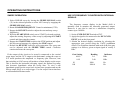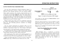
1
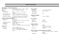
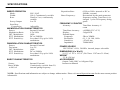
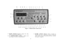
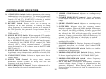
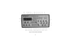
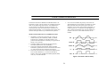
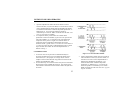
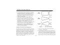
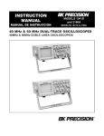
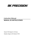
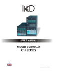
INSTRUCTION MANUAL Model 4040A MANUAL DE INSTRUCCIÓN MODELO 4040A 20 MHz SWEEP/FUNCTION GENERATOR with FREQUENCY COUNTER 20 MHz GENERADOR DE BARRIDO/FUNCIONES CON CONTADOR DE FRECUENCIA TEST INSTRUMENT SAFETY WARNING Normal use of test equipment exposes you to a certain amount of danger from electrical shock because testing must sometimes be performed where exposed voltage is present. An electrical shock causing 10 milliamps of current to pass through the heart will stop most human heartbeats. Voltage as low as 35 volts dc or ac rms should be considered dangerous and hazardous since it can produce a lethal current under certain conditions. Higher voltages pose an even greater threat because such voltage can more easily produce a lethal current. Your normal work habits should include all accepted practices to prevent contact with exposed high voltage, and to steer current away from your heart in case of accidental contact with a high voltage. You will significantly reduce the risk factor if you know and observe the following safety precautions: 1. Don't expose high voltage needlessly. Remove housings and covers only when necessary. Turn off equipment while making test connections in high-voltage circuits. Discharge high-voltage capacitors after removing power. 2. If possible, familiarize yourself with the equipment being tested and the location of its high voltage points. However, remember that high voltage may appear at unexpected points in defective equipment. 3. Use an insulated floor material or a large, insulated floor mat to stand on, and an insulated work surface on which to place equipment: and make certain such surfaces are not damp or wet. 4. Use the time proven "one hand in the pocket" technique while handling an instrument probe. Be particularly careful to avoid contacting a nearby metal object that could provide a good ground return path. 5. When testing ac powered equipment, remember that ac line voltage is usually present on some power input circuits such as the on-off switch, fuses, power transformer, etc. any time the equipment is connected to an ac outlet, even if the equipment is turned off. (continued on inside back cover) 2 Instruction Manual for Model 4040A 20 MHz SWEEP/FUNCTION GENERATOR with FREQUENCY COUNTER 22820 Savi Ranch Parkway • Yorba Linda, CA 92887 3 TABLE OF CONTENTS TEST INSTRUMENT SAFETY ...........inside front cover Voltage Controlled Frequency Operation ........................17 INTRODUCTION ........................................................ 5 Sweep Operation............................................................ 18 SPECIFICATIONS ...................................................... 6 Use of Frequency Counter with External Signals ............ 18 CONTROLS AND INDICATORS ................................ 8 Output Protection Considerations ................................... 19 OPERATING INSTRUCTIONS ................................. 11 Frequency and Waveform Selection . ......................... .11 Duty Cycle Control ................................................... 13 Burst Operation ......................................................... 14 AM Operation ........................................................... 15 FM Operation . ........................................................... 16 TTL/CMOS Output ................................................... 17 Function Generator Applications Guidebook .................. 19 MAINTENANCE ..........................................................20 Fuse Replacement .......................................................... 20 Instrument Repair Service ..............................................20 Customer Support ...........................................................21 WARRANTY SERVICE INSTRUCTIONS .................... 22 LIMITED TWO-YEAR WARRANTY ............................ 23 SPANISH MANUAL ......................................................25 4 INTRODUCTION The B&K Precision Model 4040A Sweep/Function Generator is a versatile signal source which combines several functions into one unit - waveform generation, pulse generation (through variable symmetry), and frequency sweep. Additionally, the instrument provides the added convenience of a built-in frequency counter. This permits more accurate determination of output frequency than is possible with a simple calibrated dial. Coarse and fine tuning controls permit precision stability of the output frequency. The internal frequency counter can also be used to measure external frequencies. The sweep generator offers linear or log sweep with variable sweep rate and adjustable sweep time. Front panel controls allow the start and stop frequencies to be set. Burst operation enables the output to be gated by an internal, adjustable signal or by an externally applied signal. Variable symmetry of the output waveform converts the instrument to a pulse generator capable of generating rectangular waves or pulses, ramp or sawtooth waves, and slewed sine waves. The five-digit frequency counter displays the generator output frequency or external signals from 5 to 30MHz. The output can be either amplitude modulated or frequency modulated. Modulation can be by a 1 kHz internal, adjustable signal or by an externally applied signal. With this versatility, the unit has a vast number of applications in both analog and digital electronics in the engineering, manufacturing, servicing, educational, and hobbyist fields. In addition to the above features, an external voltage may be used to control operating frequency. This is useful in situations where an externally controlled frequency is desirable. The heart of the function generator is a VCG (voltage-controlled generator) that produces precision sine, square, or triangle waves over the 0.2Hz to 20MHz range. This encompasses subaudible, audio, ultrasonic, and RF applications. A continuously variable dc offset allows the output to be injected directly into circuits at the correct bias level. Many functions can be operated simultaneously, making possible such complex outputs such as gated pulse trains with external or internal sweep. 5 SPECIFICATIONS FREQUENCY CHARACTERISTICS Waveforms: Sine, Square, Triangle, ± Pulse, ± Ramp Range: 0.2Hz to 20MHZ in 8 ranges Resolution: Tuning Range: Coarse: 10:1, Fine: ± 5% of Coarse Setting Variable Duty Cycle 15:85:15 Continuously Variable Operating Modes Normal, Sweep, VCG, AM, FM, Burst Frequency Stability: The output will change less than 0.09% over 15 minutes after 1 hour warmup. OUTPUT CHARACTERISTICS Impedance: 50Ω ± 10% Level: 20V p-p Open-circuit, 10V p-p into 50Ω to 10MHz Amplitude Control: Variable, 20dB range typical Attenuation: -20dB ±1dB Dc Offset: Preset: ±0.V typical Variable: ±10V open-circuit, ±5V into 50Ω Sine Wave Distortion: 0.1Hz to 100KHz: ≤3% Flatness: ±5% (0.45 dB) 10Hz to 8MHZ ±2 0 % ( 2.0 dB) 8MHZ to 20MHZ @ 3Vp-p Square Wave Symmetry: Rise Time: Overshoot & Undershoot ≤2% 0.2Hz to 100kHz ≤30ns (Typical) ≤5% TRIANGLE WAVE Linearity: ≥98% to 100kHz TTL OUTPUT Level: Rise Time: Duty Cycle: > 2.4V ≤20 nS 50% typical CMOS OUTPUT Max Frequency: Level: Rise Time: 2MHz 4V to 14V ±0.5V p-p, continuously variable ≤120nS VCG (Voltage Controlled Generator) INPUT Input Voltage: 0-10V ± 1V causes a 100:1 frequency change Impedance: 10kΩ ±5% 6 SPECIFICATIONS SWEEP OPERATION Mode: Width: Rate: Repetition Rate: LIN / LOG 100:1, Continuously variable 20mS to 2 sec, continuously variable 0 to 2V Sweep Output: Start/Stop Frequencies: Adjustable AM MODULATION CHARACTERISTICS Source: Internal, External Modulation Ratio: 0 To 100% INT. Modulation: 1kHz EXT. Modulation: DC to 500KHz EXT. Sensitivity: Less than 10V p-p for 100% modulation FM MODULATION CHARACTERISTICS Source: Internal, External Deviation: 0 to 5% INT. Modulation: 1kHz EXT. Modulation: DC to 500kHz EXT. Sensitivity: Less than 10V p-p for 100% modulation BURST CHARACTERISTICS Source: Burst Width: to 90% of Internal, External Continuously variable from 5% internal gating frequency Burst Frequency: 0.5Hz to 50Hz, internal or DC to 500kHz, external Determined by the main generator frequency setting. Tone burst is in integral cycles of frequency being gated. FREQUENCY COUNTER Accuracy: Time Base Accuracy ±1 count Time Base Accuracy: ±10PPM (23°C ±5°C) Display: 5 digit LED External Input: Frequency: 5Hz to 30MHz Resolution: 0.1, 1, 10, 100, 1 kHz Sensitivity: ≤25 mV rms Impedance: 1 MΩ/100 Pf POWER SOURCE 120/230VAC ±10%, 50/60Hz, internal jumper selectable DIMENSIONS (H x W x D) 10 1/2" x 5 1/2" x 12 3/8" ( 26.67cm x 13.97cm x 31.43cm ) WEIGHT 5.3 lb. (2.4 kg.) ACCESSORIES Output Cable, BNC to Alligator Clips Instruction Manual NOTE: Specifications and information are subject to change without notice. Please visit www.bkprecision.com for the most current product information. 7 CONTROLS AND INDICATORS FRONT PANEL (Refer to Fig. 1) 1. POWER Switch. Turns power on and off. 2. DUTY CYCLE Switch. When engaged, enables operation of DUTY CYCLE control (7). 3. CMOS LEVEL Switch. When engaged, changes the TTL signal to CMOS signal at the TTL/CMOS jack, and enables operation of CMOS LEVEL Control (8). 4. DC OFFSET Switch. When engaged, enables operation of the DC OFFSET control (11). 5. -20dB Switch. When engaged, the signal at the OUTPUT jack is attenuated by 20dB. 6. RANGE Switch. Selects output frequency range. Eight ranges from 2Hz to 20MHz. Switch indicates maximum frequency of range and is adjusted with COARSE FREQUENCY control to 0.1 times the maximum. For example, if the 200 kHz range is selected, the output frequency can be adjusted from 20kHz to 200kHz. 7. DUTY CYCLE Control. Activated by the DUTY CYCLE Switch (2). Rotation from center position adjusts the duty cycle of the main OUTPUT signal and TTL/CMOS signal. 8. CMOS LEVEL Control. Rotating this control clockwise increases the amplitude of the CMOS signal at the TTL/CMOS jack. 9. FUNCTION Switch. Selects sine, square, or triangle waveform at OUTPUT jack. 10. OUTPUT LEVEL Control. Controls the amplitude of the signal at the OUTPUT jack. Output level can be decreased by approximately 20dB with this control. 11. DC OFFSET Control. Activated by the DC OFFSET Switch (4). Clockwise rotation from center changes the DC offset in a positive direction while counterclockwise rotation from center changes the DC offset in a negative direction. 12. VCG/MOD INPUT Jack. Controlled by MODULATION OFF/ON Switch (33). When MODULATION OFF is selected, jack is the Voltage Controlled Generator input and permits external control of generator output frequency by a DC voltage input at this jack. A positive voltage will decrease frequency. When MODULATION ON is selected, jack becomes modulation input source. 13. OUTPUT Jack. Waveform selected by FUNCTION Switch as well as the superimposed DC OFFSET voltage is available at this jack. 14. BURST INPUT Jack. Input for external gating signal for Burst operation. 15. TTL/CMOS Jack. TTL or CMOS square wave, depending on the position of the CMOS LEVEL switch (3) is output at this jack. This output is independent of the OUTPUT LEVEL and DC OFFSET controls. 16. EXT. COUNTER INPUT Jack. Input for external frequency measurements. 8 Figure 1. Model 4040A Front Panel. 19 BURST OFF/ON Switch. Selects external or internal burst gate. Continuous output is obtained with switch in the OFF position and no external burst gate is applied. 17. BURST WIDTH Control. Adjusts the duty cycle of the internal burst gate. 18. % MODULATION Control. Adjusts the percentage of AM or FM modulation. 9 CONTROLS AND INDICATORS 20. .START/STOP Switch. Enables adjustment of the starting and stopping sweep frequencies. The actual adjustment is performed by the SWEEP START and SWEEP STOP controls (29 and 27). START/STOP selection is enabled only when the SET/RUN switch (21) is set to SET. 21. RUN/SET Switch. Selects sweep set or sweep run operation. In the SET position, the starting or ending sweep frequency is continuously present at the output. In the RUN position, the generator sweeps between the low and the high frequencies at a rate set by the SWEEP TIME control. 22. SWEEP EXT/INT Switch. When engaged (INT) enables the sweep mode of operation. Sweep rate is controlled by SWEEP TIME control (25) and sweep length is controlled by the SWEEP STOP control (27) and the start frequency is controlled by the SWEEP START control (29). When released (EXT), allows external control of generator output frequency by a DC voltage input at the VCG/MOD INPUT jack (12). 23. SWEEP LIN/LOG Switch. When engaged (LOG) selects logarithmic sweep characteristic and when released (LIN) selects a linear sweep characteristic. 24. CNTR INT/EXT Switch. Selects the input source for the counter input. 25. SWEEP TIME Control. In sweep mode, rotation determines amount of time to sweep from the start frequency to the stop frequency. 26. FINE FREQUENCY Control. Vernier adjustment of the output frequency for ease of setting frequency. 27. SWEEP STOP Control. Adjusts the ending sweep frequency. 28. COARSE FREQUENCY Control. Coarse adjustment of the output frequency from 0.1 to 1 times the selected range. 29. SWEEP START Control. Adjusts the starting sweep frequency. 30. GATE LED. Indicates when the frequency counter display is updated. When the 200K through 20M ranges are selected, the LED will flash 10 times per second (every 0.1 seconds). When the 20 through 20K ranges are selected, the LED will flash once every second and when the 2 range is selected, the LED will flash every 10 seconds. As the LED turns off, the display is updated. 31. Hz and KHz LED. Indicates whether the counter is reading in Hz or KHz. 32. COUNTER DISPLAY. Displays frequency of internally generated waveform, or external signal when CNTR EXT is selected. 33. MODULATION ON/OFF Switch. Enables or disables modulation of the generator. 34. MODULATION EXT/INT Switch. Selects whether generator modulation is from the internal 1 KHz source or from a signal applied to the VCG/MOD INPUT jack. 35. MODULATION FM/AM Switch. Selects Frequency modulation or Amplitude modulation. 36. GCV OUTPUT. (Located on back panel) Generator control voltage output. Voltage is proportional to the generator frequency. When Sweep mode is selected sweep voltage is present at this jack for connection to an oscilloscope. 10 OPERATING INSTRUCTIONS The B&K Precision Model 4040A Sweep/Function Generator is a versatile instrument, capable of producing a variety of output waveforms over a broad range of frequencies. To gain a working familiarity with the unit, it is recommended that it be connected initially to an oscilloscope, so that the effects of the various controls on the output waveforms can be observed. Use this manual as required for reference until becoming accustomed to the operating procedures. 5. Rotate the COARSE (28) frequency control to quickly set the output frequency to the approximate desired value. The FINE (26) frequency control can then be used to easily set the output to the specific desired value. The frequency selected is available at the OUTPUT jack (13). In addition, a digital signal, either TTL or CMOS is available at the TTL/CMOS jack (15) (refer to the “TTL/CMOS OUTPUT” section of this manual). FREQUENCY AND WAVEFORM SELECTION l. Initially, verify that the DUTY CYCLE (2), CMOS LEVEL (3), DC OFFSET (4), -20dB (5), and SWEEP EXT/INT (22), and AM/FM (35) switches are in the released position. This will produce a symmetrical waveform unaffected by the sweep generator and other controls. 2. Plug the unit into an appropriate power source and turn it on by depressing the POWER switch (1). 3. Select the desired waveform (SINE, SQUARE, or TRIANGLE) by depressing one of the FUNCTION switches (9). Phase relationships of the waveforms are shown in Fig. 2. 4. Select the frequency of the waveform by depressing one of the RANGE switches (6). The output frequency is displayed, along with the appropriate measurement units. KHz or Hz (31), on the LED display. Figure 2. Output Waveform and Phase Relationship 11 OPERATING INSTRUCTIONS 6. Adjust the amplitude of the output as desired using the OUTPUT LEVEL control (10). Rotation of this control varies the amplitude from maximum to 20dB below maximum. An additional attenuation of -20dB is available by pushing in the -20dB switch (5). The attenuation factors can be combined for a total of -40dB. The maximum signal level is 10V p-p (into 50Ω). 7. A DC component can be added to the output signal by pushing in the DC OFFSET switch (4) to enable operation of the DC OFFSET control (11). Rotation of this control adds a positive or negative DC component to the output signal. The DC component introduced is independent of the OUTPUT LEVEL control and can be varied by ±10 volts open circuited or ±5 volts into 50Ω. The DC Offset does not affect the TTL/CMOS output jack. The effect of DC OFFSET is shown in Fig. 3. Considerations l. Counterclockwise rotation of the COARSE frequency control decreases the output frequency to approximately onetenth of the maximum for the range selected (10:1). For example, if the 10K range is selected and the COARSE frequency control is set to full counterclockwise, the output frequency is approximately 1 kHz. 2. It is advisable to set the FINE frequency control to the approximate center of its rotation before setting the COARSE frequency control. This assures that the FINE control will not reach its limit while trying to finalize the frequency setting. Figure 3. Use of DC OFFSET Control 3. The FINE frequency control provides approximately ±5% frequency deviation from the COARSE control setting. This provides vernier adjustment to easily set the frequency to a precise value. 12 OPERATING INSTRUCTIONS 4. When the 2 Hz range is selected, the gate time is 10 seconds and the display is updated once every 10 seconds. The result of a frequency change will not be displayed until 10 seconds later. Adjust the frequency in progressively smaller steps, waiting for the display to update until the desired frequency is obtained. 5. When outputting square waves or when using the TTL output, terminate the cable into 50Ω to minimize ringing. Also, keep cables as short as possible. 6. Remember that the output signal swing of the generator is limited to ±10 volts open circuited or ±5 volts into 50Ω, and applies to the combined peak-to-peak signal and DC offset. Clipping occurs slightly above these levels. Fig. 3 illustrates the various operating conditions encountered when using the DC offset. If the desired output signal is large or if a large DC offset is required, an oscilloscope should be used to make sure that the desired signal is obtained without undesirable clipping. DUTY CYCLE CONTROL The DUTY CYCLE control can be used to alter the symmetry of the output waveform, to produce waveshapes such as those shown in Fig. 4. For a square wave, symmetry variation amounts to changing the duty cycle (ratio of "high" to "low" time), effectively converting the instrument into a pulse generator. For a triangle wave, the result is a ramp, and with a sine wave, a distorted waveshape called a slewed sine is produced. The Model 4040 provides for symmetry variation from 15% to 85%. 1. Select the waveform desired either SINE, SQUARE or TRIANGLE. 13 Figure 4. Effects of Symmetry Variation. 2. Engage the DUTY CYCLE switch (2) and adjust the DUTY CYCLE control (7) for the desired waveshape. Clockwise rotation from center results in an increase in square wave duty cycle, and changes the sine and triangle waves as shown in the top waveform of each pair of Fig. 4. Counterclockwise rotation results in the bottom waveform in each pair. OPERATING INSTRUCTIONS 3. Varying the duty cycle setting results in a slight change in frequency. Adjust the COARSE and FINE frequency controls as required. BURST OPERATION In gated burst mode of operation, the generator output is switched on and off (gated), either by an internally generated signal or by an externally applied signal. Both the repetition rate and the duty cycle are variable. Fig. 5 illustrates the type of waveform generated and summarizes the control settings used to obtain the desired waveform. Internal Triggering 1. Select the waveform to be gated by pushing in the appropriate FUNCTION switch. Display the output of the generator on an oscilloscope. 2. Adjust the frequency, amplitude, symmetry, and dc offset of the signal by using the main generator controls. 3. Enable the burst mode by pushing in the BURST ON switch. 4. Set the repetition rate of the burst with the SWEEP TIME control. 5. Adjust the tone burst duty cycle, or adjust the tone burst width to a specific time period, with the BURST WIDTH control. Figure 5. Tone burst generator output waveform. External Triggering 1. Select the waveform to be gated by pushing in the appropriate FUNCTION switch on the front panel. 2. Adjust the frequency, amplitude, symmetry, and dc offset of the signal by using the main generator controls. 14 OPERATING INSTRUCTIONS 3. With BURST ON/OFF switch in OFF position, apply a TTL gating signal of the proper width to the front panel BURST INPUT jack. AM OPERATION The output of Model 4040A can be amplitude-modulated, either by the internal 1 kHz signal, or by an external signal applied to the VCG/MOD INPUT jack. Considerations Internal l. Make sure the tone burst and entire off period is viewed when setting the repetition rate. The visible portion of the off period could be incorrectly interpreted as the entire off period. To avoid this error, use a low sweep speed on the oscilloscope, adjusted to view the tone burst, off period, and the beginning of a second tone burst. 2. The BURST WIDTH control does not interact with the SWEEP TIME control and will not affect the repetition rate. However, both controls affect the tone burst width. Since the BURST WIDTH control adjusts the duty cycle (percentage of repetition rate cycle in which tone burst is produced), any subsequent adjustment of the SWEEP TIME control affects the tone burst width, as well as the off period. When setting the tone burst width to a specific time period, adjust the SWEEP TIME control first, then the BURST WIDTH control. 3. The tone burst output signal is always in full cycles or half cycles. Note that as the BURST WIDTH control is adjusted slowly, the tone burst is increased or decreased on half cycle increments. This allows synchronization of the waveform for oscilloscope viewing and eliminates transients and frequency components not harmonically related to the frequency being gated. This feature is applicable to internal or external tone burst operation. 1. Set the carrier frequency using the main FREQUENCY controls and RANGE switches. 2. Engage the MODULATION ON and AM MODULATION switches. 3. Engage the INT MODULATION switch. 4. Set the percent of modulation by rotating the % MODULATION control. Modulation can be set in excess of 100%. Fig. 6 shows the appearance of a carrier modulated by a sine wave, and the quantities A and B which are used in measuring percentage of modulation. The formula is: Percent modulation = 2B/A x 100 Where A = unmodulated carrier level B = modulation depth External l. Set the carrier frequency using the main FREQUENCY controls and RANGE switches. 2. Engage the MODULATION ON and AM MODULATION switches. 15 OPERATING INSTRUCTIONS 3. Place the EXT MODULATION switch in the released position. 4. Connect a suitable modulating signal to the VCG/MOD INPUT jack on the front panel. 5. Adjust the modulation level as described previously. FM OPERATION The output of the Model 4040 can be frequency-modulated, either by the internal 1 kHz internal signal or by an external signal applied to the front panel VCG/MOD INPUT jack. Internal 1. Set the carrier frequency using the main FREQUENCY controls and RANGE switches. 2. Engage the MODULATION ON switch and release the MODULATION FM/AM switch. 3. Engage the INT MODULATION switch. 4. The amount of deviation can be varied by rotating the % M O D U LATION control. External 1. Set the carrier frequency using the main FREQUENCY controls and RANGE switches. 2. Engage the MODULATION ON switch and release the MODULATION FM/AM switch. 3. Place the EXT MODULATION switch in the released position. Figure 6. Examples of AM modulation 16 OPERATING INSTRUCTIONS 4. Connect a suitable modulation signal to the VCG/MOD INPUT jack on the front panel. 5. Adjust the amplitude and frequency of the external signal as required. Typically, a signal less than 10V pp will provide 10% modulation of the carrier. will vary the frequency which is pre-selected by the range switches and the frequency controls. Applying approximately +l0 V with the COARSE control at full clockwise decreases the output frequency by about 100 times (a 100:1 ratio). TTL/CMOS OUTPUT 1. Select the desired frequency range and waveform. 2. Set the starting frequency with the COARSE control. Apply a positive DC voltage to the VCG/MOD INPUT jack (l2) to decrease the frequency. A voltage from 0 to +10 V will cause the frequency to decrease by a factor of 100 if the COARSE frequency control is set at maximum CW rotation. For example, if the starting frequency is 100 kHz, applying +10 V will change the output frequency to 1 kHz. 3. To operate the function generator as a sweep generator, apply a positive-going ramp signal to the VCG/MOD input jack. As the ramp voltage increases, the frequency decreases. The rate of sweep can be adjusted by varying the frequency of the ramp signal. 4. Specific frequencies can be selected by applying a fixed dc voltage to the VCG/MOD INPUT jack or the frequencies can be stepped by applying a stepped dc voltage. 5. Do not apply more than ±15 volts (dc or dc + ac peak) to the VCG/MOD INPUT jack. Inputs of more than 15 volts will not cause any further shift in the frequency and could cause damage to the generator. The TTL/CMOS output jack provides a fast rise time square wave output. Either a fixed TTL or a variable CMOS output level is available. The output is positive with respect to ground and can be used as an external sync pulse for oscilloscopes or as a variable frequency signal source for exercising logic circuits. Because of the fast rise time of this output, cable length should be minimized to limit ringing and overshoot. 1. Select the desired frequency range and adjust the frequency controls as required. The OUTPUT LEVEL and DC OFFSET controls have no effect on the signal at the TTL/CMOS jack. 2. When the CMOS LEVEL switch (3) is released, a TTL signal is output at the TTL/CMOS jack. Select a CMOS signal by engaging the CMOS LEVEL switch and adjust the level of the signal by rotating the CMOS LEVEL control (8). VOLTAGE CONTROLLED FREQUENCY OPERATION The Model 4040A can be operated as a voltage-controlled generator by using an external control voltage applied to the VCG/MOD INPUT jack (12). The externally applied voltage 17 OPERATING INSTRUCTIONS SWEEP OPERATION USE OF FREQUENCY COUNTER WITH EXTERNAL SIGNALS 1. Select LINEAR sweep by leaving the SWEEP LIN/LOG switch (23) in the released position or select LOG sweep by engaging the SWEEP LIN/LOG switch. The frequency counter display in the Model 4040 is normally used to monitor the internally generated output. However, it can also be used as a stand-alone frequency counter up to 30 MHz. 2. Rotate COARSE FREQUENCY Control to minimum (CCW). 3. Engage the RUN/SET switch to adjust the start and stop sweep frequencies. 4. With the START/STOP switch set to START (released position), adjust the starting frequency of the sweep by adjusting the START control and observing the counter. 5. Engage the START/STOP switch to the STOP position and adjust the stop sweep frequency by adjusting the STOP control. 6. Release the RUN/SET switch for sweep operation. The sweep rate can be adjusted with the SWEEP TIME control. Clockwise rotation increases the sweep rate. 1. Set the CNTR INT/EXT switch to EXT. 2. Apply the signal to be measured to the EXT CNTR INPUT jack on the front panel. 3. Obtain the desired display resolution by selecting the appropriate gate period using the GATE pushbutton switch. The resolution obtained with each of the four gate settings is as follows, given an input signal of exactly 2 KHz. If the output of the circuit to be tested is connected to the vertical scope input, and the GCV output to the horizontal, setting the scope to X-Y mode produces the amplitude vs. frequency plot. However, note that switching to LOG sweep still produces a linear display on the scope. This is because the horizontal sweeping signal, the internal log ramp, also becomes logarithmic when the sweep does. To view a true logarithmic graph, put the scope back in time base operation and use the Sweep output solely as a scope trigger. Use the scope's linear time base as a horizontal deflection source. Gate Setting 0.01S 0.1S 1S 10S 18 Reading 2.0 2.00 2000 2000.0 Indicator KHz KHz Hz Hz OPERATING INSTRUCTIONS OUTPUT PROTECTION CONSIDERATIONS Use care when connecting the function generator output to a signal injection point. Excessive voltage at the point of signal injection of the function generator can cause internal damage. Under normal operation, the generator output should never be connected to an external voltage other than low dc values that can be matched with the DC OFFSET control. The Model 4040 is overload protected so that shorting the output, even continuously, will not cause damage. A fuse has been added in series with the OUTPUT jack to help protect the instrument from damage by connection to excessive external voltage. Damage of this type usually occurs by accidentally connecting the output of the function generator to a voltage in the equipment under test. The following protective measures are strongly recommended: The user should understand the equipment under test well enough to identify valid signal injection points (e.g., the base of a transistor, a logic input of a gate, etc.). The voltage at valid signal injection points is rarely high enough to damage the instrument. If in doubt about the safety of a signal injection point, measure the voltage present at the intended point of signal injection before connecting the function generator output to that point. When applying the main output of the function generator to a circuit point containing a dc level, adjust the DC OFFSET control so that the dc level at the main output matches the circuit voltage. Connect the TTL output only to TTL-level circuits. Connect the CMOS output only to CMOS circuits. Measure the Vcc of the 19 Figure 7. Circuit for Protection of TTL Output. circuit under test and adjust the CMOS LEVEL control as instructed in the manual. When the function generator is used by students or other inexperienced users, the circuit shown in Fig. 7 could be added into your TTL output probe or test clip set. It will protect the TTL output of the generator against external voltages up to ± 20 volts. FUNCTION GENERATOR APPLICATIONS GUIDEBOOK B+K Precision offers a “Guidebook to Function Generators” which describes numerous applications for this instrument, including hook-up details. It also includes a glossary of function generator terminology and an explanation of function generator circuit operation. It maybe downloaded for free off our website at www.bkprecision.com. MAINTENANCE WARNING The following instructions are for use by qualified service personnel only. To avoid electrical shock, do not perform servicing other than contained in the operating instructions unless you are qualified to do so. Remember that ac line voltage is present on line voltage input circuits any time the instrument is plugged into an ac outlet, even if turned off. Always unplug the function generator before performing service procedures. INSTRUMENT REPAIR SERVICE Because of the specialized skills and test equipment required for instrument repair and calibration, many customers prefer to rely upon B+K PRECISION for this service. We maintain a network of B+K PRECISION authorized service agencies for this purpose. To use this service, even if the instrument is no longer under warranty, follow the instructions given in the WARRANTY SERVICE INSTRUCTIONS portion of this manual. There is a nominal charge for instruments out of warranty. FUSE REPLACEMENT 1. Locate the fuse holder on the input line receptacle. 2. Remove the fuse holder and replace the fuse with an equal value fuse 20 CUSTOMER SUPPORT 1-800-462-9832 B+K Precision offers courteous, professional technical support before and after the sale of their test instruments. The following services are typical of those available from our toll-free telephone number: Technical advice on the use of your instrument. Technical advice on special applications of your instrument. Technical advice on selecting the best instrument for a given task. Information on optional accessories for your instrument. Information on instrument repair and recalibration services. Replacement parts ordering. Availability of service publications. Information on other B+K Precision instruments. Requests for a new B+K Precision catalog. The name of your nearest B+K Precision distributor. Call toll-free 1-800-462-9832 Monday through Thursday, 8:00 A.M. to 5:00 P.M, Friday 8:00 A.M. TO 11:30 A.M. Pacific Standard Time (Pacific Daylight Time summer) 21 Service Information Warranty Service: Please return the product in the original packaging with proof of purchase to the address below. Clearly state in writing the performance problem and return any leads, probes, connectors and accessories that you are using with the device. Non-Warranty Service: Return the product in the original packaging to the address below. Clearly state in writing the performance problem and return any leads, probes, connectors and accessories that you are using with the device. Customers not on open account must include payment in the form of a money order or credit card. For the most current repair charges please visit www.bkprecision.com and click on “service/repair”. Return all merchandise to B&K Precision Corp. with pre-paid shipping. The flat-rate repair charge for Non-Warranty Service does not include return shipping. Return shipping to locations in North American is included for Warranty Service. For overnight shipments and non-North American shipping fees please contact B&K Precision Corp. B&K Precision Corp. 22820 Savi Ranch Parkway Yorba Linda, CA 92887 www.bkprecision.com 714-921-9095 Include with the returned instrument your complete return shipping address, contact name, phone number and description of problem. 22 Limited Two-Year Warranty B&K Precision Corp. warrants to the original purchaser that its products and the component parts thereof, will be free from defects in workmanship and materials for a period of two years from date of purchase. B&K Precision Corp. will, without charge, repair or replace, at its option, defective product or component parts. Returned product must be accompanied by proof of the purchase date in the form of a sales receipt. To obtain warranty coverage in the U.S.A., this product must be registered by completing a warranty registration form on www.bkprecision.com within fifteen (15) days of purchase. Exclusions: This warranty does not apply in the event of misuse or abuse of the product or as a result of unauthorized alterations or repairs. The warranty is void if the serial number is altered, defaced or removed. B&K Precision Corp. shall not be liable for any consequential damages, including without limitation damages resulting from loss of use. Some states do not allow limitations of incidental or consequential damages. So the above limitation or exclusion may not apply to you. This warranty gives you specific rights and you may have other rights, which vary from state-to-state. B&K Precision Corp. 22820 Savi Ranch Parkway Yorba Linda, CA 92887 www.bkprecision.com 714-921-9095 23 TEST INSTRUMENT SAFETY (continued from inside front cover) 6. Some equipment with a two-wire ac power cord, including some with polarized power plugs, is the “hot chassis” type. This includes most recent television receivers and audio equipment. A plastic or wooden cabinet insulates the chassis to protect the customer. When the cabinet is removed for servicing, a serious shock hazard exists if the chassis is touched. Not only does this present a dangerous shock hazard, but damage to test instruments or the equipment under test may result from connecting the ground lead of most test instruments to a “hot chassis”. To test “hot chassis” equipment, always connect an isolation transformer between the ac outlet and the equipment under test. The B+K Precision Model TR-110 or 1604 Isolation Transformer, or Model 1653 or 1655 AC Power Supply is suitable for most applications. To be on the safe side, treat all two-wire ac equipment as “hotchassis” unless you are sure it has an isolated chassis or an earth ground chassis. 7. On test instruments or any equipment with a 3-wire ac power plug, use only a 3-wire outlet. This is a safety feature to keep the housing or other exposed elements at earth ground. 8. B+K Precision products are not authorized for use in any application involving direct contact between our product and the human body, or for use as a critical component in a life support device or system. Here, “direct contact” refers to any connection from or to our equipment via any cabling or switching means. A “critical component” is any component of a life support device or system whose failure to perform can be reasonably expected to cause failure of that device or system, or to affect its safety or effectiveness. 9. Never work alone. Someone should be nearby to render aid if necessary. Training in CPR (cardio-pulmonary resuscitation) first aid is highly recommended. 24 SEGURIDAD DEL INSTRUMENTO DE PRUEBA PRECAUCIONES El Uso normal de equipo de prueba lo expone a cierto riesgo de choque eléctrico cuando efectúa pruebas donde hay alto voltaje descubierto. Un choque eléctrico que cause una corriente de 10 mili amperes a través del corazón pararía la mayoría de los corazones humanos. Un voltaje tan bajo como de 35 volts DC o AC rms podría considerarse de peligro porque puede producir una corriente letal bajo ciertas condiciones. Voltajes mayores pueden ser aun más peligrosos. Sus hábitos normales de trabajo deben de incluir todas las prácticas aceptadas para prevenir descargas de alto voltaje, y desviar la corriente lejos del corazón en caso de contacto accidental con un alto voltaje. Puede reducir el factor de riesgo significativamente si observa las siguientes medidas de seguridad: 1. No se exponga a altos voltajes sin necesidad. Remueva la caja y tapas solo cuando sea necesario. Apague el equipo cuando haga conexiones de prueba en circuitos de alto voltaje. Descargue los capacitores de alto voltaje después de apagar. 2. Si es posible, familiarícese usted mismo con el equipo por revisar y la localización de los puntos de alto voltaje. Considere, sin embargo, que un voltaje alto puede aparecer en puntos inesperados en equipo defectuoso. 3. Use un piso de material aislante o un tapete aislante largo para situarse, y una superficie de trabajo aislante en la cual pueda poner el equipo; asegúrese que las superficies no estén húmedas o mojadas. 4. Use la probada técnica de mantener “una mano en la bolsa” cuando este usando una sonda o punta de prueba del instrumento. Evite con particular cuidado tocar un objeto metálico que pueda proveer un buen retorno a tierra. 5. Cuando revise un equipo conectado a voltaje de AC, recuerde que el voltaje está usualmente presente en algunos circuitos de entrada tal como el switch de encendido y apagado, fusibles, transformadores de poder, etc. mientras el equipo esté enchufado a una toma de AC aun aún cuando esté apagado. (continuó la cubierta de espalda) 25 MANUAL DE USUARIO MODELO 4040A 20MHz GENERADOR DE BARRIDO/FUNCIONES CON CONTADOR DE FRECUENCIA 22820 Savi Ranch Parkway • 26 Yorba Linda, CA 92887 TABLA DE CONTENIDO SEGURIDAD DEL INSTRUMENTO DE PRUEBA Operación de la frecuencia controlada por voltaje ....................40 INTRODUCION .......................................................... 28 Operación de barrido .................................................................41 ESPECIFICACIONES ................................................. 29 Uso del contador de frecuencia con señales externas................41 CONTROLES E INDICADORES ............................... 31 Consideraciones de protección de salida....................................42 INSTRUCCIONES DE OPERACIÓN ........................ 34 Guía de aplicaciones del generador de funciones......................42 Selección de frecuencia y forma de onda ..................... 34 MANTENIMIENTO.................................................................43 Consideraciones ........................................................... 35 Reemplazo de fusible ...............................................................43 Control de ciclo de servicio.......................................... 36 Servicio de reparación del instrumento.....................................43 Operación de ráfaga...................................................... 37 SOPORTE AL CLIENTE.........................................................44 Operación AM.............................................................. 38 INSTRUCCIONES PARA EL SERVICIO DE GARANTIA...45 Operación FM .............................................................. 39 GARANTIA LIMITADA DE DOS AÑOS ..............................46 Salida para TTL/CMOS ............................................... 40 27 INTRODUCCIÓN El B & K Precision modelo 4040A Barrido/Función generador es una versátil fuente de señales que combina varias funciones en una unidad- generador de formas de onda, generador de pulsos (a través de simetría variable), y barrido de frecuencia. Adicionalmente, el instrumento provee la conveniencia adicional de incluir un contador de frecuencia. Esto permite una determinación mas precisa de la frecuencia de salida que la que provee un cuadrante (dial) calibrado. Controles de ajuste grueso y fino permiten ajustar con precisión la frecuencia de salida. El contador de frecuencia de 5 dígitos exhibe la frecuencia del generador o de señales externas desde 5 a 30Mhz. Una operación de ráfaga permite que la salida se interrumpa o active mediante una señal interna ajustable, o por una señal externa La simetría variable de la forma de salida convierte al instrumento en un generador de pulsos capaz de generar ondas rectangulares o pulsos, ondas de rampa o diente de sierra y senoidales inclinadas. La salida puede modularse en frecuencia o amplitud. La modulación se genera por una señal interna de 1 Khz., o por una señal externa. Con esta versatilidad, la unidad tiene un amplio número de aplicaciones tanto en electrónica analógica como digital en los campos de ingeniería, manufactura, servicio, educación y recreación. Además de estas características, puede usar un voltaje externo para controlar la frecuencia de operación. El instrumento permite la operación de muchas funciones simultáneas, lo que permite la generación de salidas complejas como trenes de pulsos interrumpidos con barrido interno o externo. El corazón del generador de funciones es un VCG (generador controlado por voltaje) que produce ondas de seno, cuadradas y triangulares precisas desde los 0.2Hz hasta 20MHz, para aplicaciones subaudibles, de audio, de ultrasonido y RF. Un desplazamiento (offset) de DC de variación continua permite inyectar la señal directamente en circuitos con la polarización correcta. 28 ESPECIFICACIONES CARACTERÍSTICAS DE FRECUENCIA Formas de onda : seno,cuadrada,triangular, ±pulso,±rampa Rango : 0.2Hz a 20MHz en 8 rangos Resolución : 5 dígitos Rango de sintonía : grueso 10:1, Fino ±5% de posición gruesa Ciclo de servicio variable : 15:85:15 continuamente variable Modos de operación : normal,barrido,VCG, AM, FM, ráfaga CARACTERÍSTICAS DE SALIDA Impederica : 50Ω ± 10% Nivel : 20V p-p circuito abierto,10Vp-p a 50 OHMS a 10Mhz Control de amplitud : Variable, 20db rango tipico Atenuación :-20db±1db Compensación DC (offset) :Variable ±10V circuito abierto ,±5V a 50Ω : Preestablecido ±1 V típico ONDA SENOIDAL Distorsión Aplanado ONDA CUADRADA Simetría Tiempo de elevación Sobretensión :0.2Hz a 100KHz ≤ 2% :≤ 30 nS (Típico) : ≤ 5% ONDA TRIANGULAR Linealidad :≥ 98% a 100KHz SALIDA TTL Nivel Tiempo de elevación Ciclo de servicio :0.8V a 2.4V : ≤ 20ns : 50% típico SALIDA CMOS Frecuencia máxima Nivel Tiempo de elevación : 2MHz : 4V a 14V ±0.5V p-p continuamente variable : ≤ 120ns ENTRADA DE VCG(generador controlado por voltaje) Voltaje de entrada : 0-10V ±1V causa un cambio de frecuencia 100:1 Impedancia : 10KΩ ± 5% : ≤ 3% de 0.1Hz a 100KHz : ±5% (.45dB) 10Hz a 10MHz : ±20% (2 dB) 10Mhz a 20MHz 29 ESPECIFICACIONES CARACTERISTICAS DE RAFAGA Fuente : Interna, externa Ancho de ráfaga : Variable continuamente del 5% al 90% de la frecuencia interna de interrupción OPERACIÓN DE BARRIDO Modo : LIN/LOG Ancho : 00:1,continuamente variable Velocida : 20ms a 2s continuamente variable Salida de barrido : 0 a 2V Frecuencia de inicio/paro : Ajustable Razón de repetición CARACTERISTICAS DE MODULACION AM Fuente : Interna, externa Desviación : 0 a 5% Modulación INT : 1KHz Modulación EXT : DC a 500KHz Sensitividad EXT : Menos de 10V p-p para 100% de modulación : 0.5Hz a 50Hz interna o DC a 500KHz externa Frecuencia De la Explosión: : Determinada por lo establecido para el generador principal. El tono de ráfaga está en ciclos integrales de la frecuencia de interrupción CONTADOR DE FRECUENCIA Precisión :Precisión de la base de tiempo ± 1 cuenta Precisión de base de tiempo : ± 10ppm (23°C ± 5°C) Pantalla : 5 dígitos tipo LED Fuente externa Frecuencia : 5Hz a 30MHz Resolución : 0.1, 1, 10, 100, 1KHz Sensitividad : ≤ 25mV rms Impedancia : 1MΩ/ 100pF FUENTE DE PODER : 120/230VAC ± 10% 50/60Hz Selección por jumper interno DIMENSIONES : 10 1/2”x5 1/2”x12 3/8” (26.67x13.97x31.43 cm) NOTA: Las especificaciones y la información están conforme a cambio sin el aviso de B&K Precision Corp. Por favor visite www.bkprecision.com para las especificaciones más corriente y información de nuestros productos. 30 CONTROLES E INDICADORES PANEL DELANTERO (Vea la Fig. 1) 1. INTERRUPTOR DE ENCENDIDO (POWER). Enciende y apaga el instrumento. 2. Switch DUTY CYCLE. Su activación habilita la operación del control DUTY CYCLE(7). 3. Switch CMOS LEVEL. Accionado, cambia la señal TTL a señal CMOS en el jack TTL/CMOS jack, y permite la operación del Control CMOS LEVEL (8) 4. Switch DC OFFSET. Al accionarse se habilita la operación del control DC OFFSET(11). 5. –20 DB SWITCH. Al accionarse, la señal del jack de salida es atenuada por –20 dB. 6. SWITCH DE RANGO (RANGE). Selecciona el rango de la frecuencia de salida. 8 rangos de 2Hz a 20MHz. El switch indica la máxima frecuenta del rango y se ajusta con el control grueso de frecuencia a 0.1 veces el máximo. Por ejemplo, si el rango de 200kHz es seleccionado, la salida de frecuencia puede ser ajustada de 20kHz a 200kHz 7. CONTROL DEL CICLO DE SERVICIO (DUTY CYCLE). Activado por el switch DUTY CYCLE(2). La rotación desde la posición central ajusta el ciclo de servicio de la señal de la salida principal OUTPUT y de la señal TTL/CMOS 8. CONTROL DE NIVEL CMOS (LEVEL). Girando este control en la dirección de las manecillas del reloj aumenta la amplitud de la señal CMOS al jack TTL/CMOS 9. SWITCH DE FUNCIONES (FUNCTION). Selecciona la forma de onda del jack de salida : senoidal, cuadrada, triangular 10. CONTROL DE NIVEL DE SALIDA (OUTPUT LEVEL). Controla la amplitud de la señal al jack de salida. El nivel de salida puede ser disminuido por aproximadamente 20dB con este control 11. CONTROL DE DC OFFSET. Activado por el switch de OFFSET (4). La rotación en la dirección de las manecillas del reloj desde el centro cambia el desplazamiento de DC en la dirección positiva, en tanto que la rotación en contra de las manecillas del reloj desde el centro cambia el desplazamiento de DC en la dirección negativa. 12. Jack de entrada VCG/ MOD. Controlado por switch MODULATION OFF/ON (33). Al seleccionar MOD OFF, la entrada es del generador controlado por voltaje y permite el control externo la frecuencia de salida por un voltaje DC en este jack. Un voltaje positivo disminuirá la frecuencia. Con MOD ON, el jack es la fuente de entrada de la modulación 13. JACK DE SALIDA (OUTPUT). La forma de onda seleccionada por el switch de funciones así como el voltaje de desplazamiento de DC sobre impuesto está disponible en este jack. 14. Jack BURST INPUT. Entrada de la función de interrupción para el modo de Ráfaga 15. Jack TTL/CMOS . Onda cuadrada TTL o CMOS, dependiendo de la posición del switch (3) de nivel CMOS. Esta salida es independiente del los controles de NIVEL DE SALIDA y OFFSET CD . 16. Jack EXT. COUNTER INPUT. Entrada para la medición de frecuencia externa 31 CONTROLES E INDICADORES 17. Control BURST WIDTH. Ajusta el ciclo de servicio del interruptor interno de ráfaga 18. % MODULATION. Ajusta el porcentaje de modulación AM o FM 19. Switch BURST OFF/ON. Selecciona interruptor de ráfaga externa o interna. En la posición OFF la salida es continua y no se aplica la señal de ráfaga interna 20. Switch START/STOP. Permite el ajuste de las frecuencias de inicio y parado. El ajuste se efectúa mediante los controles SWEEP START Y SWEEP STOP (29 Y 27). La selección de START/STOP se habilita sólo cuando el switch SET/RUN se fija en SET. 21. Switch RUN/SET. En la posición SET, la frecuencia inicial o final de barrido está presente en forma continua en la salida. En la posición RUN, el generador barre entre frecuencias bajas y altas a una razón fijada por el control SWEEP TIME. 22. Switch SWEEP EXT/INT. La activación (INT) permite el modo de operación de barrido. La velocidad de barrido es controlada por el control SWEEP TIME(25), su longitud por el Control SWEEP STOP (27) y la frecuencia inicial por SWEEP START(29). Al desactivar el switch (EXT) la frecuencia se controla externamente por el voltaje de DC en el jack de entrada VCG/MOD INPUT (12). 23. Switch SWEEP LIN/LOG. Su activación (LOG) selecciona características de barrido logarítmico y al desengancharse (LIN) se seleccionan características de barrido lineal 24. Switch CNTR INT/EXT. Selecciona la fuente de entrada para la entrada del contador 25. Control SWEEP TIME. En el modo de barrido, su rotación determina el tiempo de barrido desde la frecuencia de inicio hasta la frecuencia final de parada 26. Control FINE FREQUENCY. Ajustes de vernier de la frecuencia de salida para un ajuste fácil de frecuencia 27. Control SWEEP STOP. Ajusta la frecuencia de barrido de parada (final) 28. Control COARSE FREQUENCY. Ajuste grueso de la frecuencia de salida de 0.1 a 1 veces el rango seleccionado 29. Control SWEEP START. Ajusta la frecuencia de inicio de barrido 30. LED gate. Indica cuando se actualiza la pantalla del contador. En los rangos de 200K a 20M, el LED relampaguea 10 veces por segundo (cada 0.1 segundos). En los rangos de 20 a 20K relampaguea una vez por segundo y en el rango 2 relampaguea cada 10 segundos. Cuando el LED se apaga, la pantalla cambia (se actualiza) 31. Hz y KHz LED. Indica si el contador esta leyendo Hz o kHz 32. PANTALLA DEL CONTADOR. Muestra la frecuencia de la forma de onda interna, o externa si se selecciona CNTR EXT 33. Switch MODULATION ON/OFF. Activa o desactiva la modulación del generador 34. Switch MODULATIN EXT/INT. Selecciona si la modulación es de la fuente interna de 1KHz o de una señal aplicada al jack VCG/MOD de entrada 35. Switch MODULATION FM/AM. Selecciona modulación de frecuencia o amplitud. 36. GCV OUTPUT (En el panel trasero). Salida del voltaje de control del generador. El voltaje es proporcional a la frecuencia del generador. Este voltaje está presente en el modo SWEEP para conectarse a un osciloscopio. 32 Figura 1. Panel frontal del modelo 4040A 33 INSTRUCCIONES DE OPERACIÓN El Generador de funciones B&K Precison Modelo 4040A es un instrumento versátil, capaz de producir una variedad de formas de onda con un amplio rango de frecuencias. Para familiarizarse con esta unidad, se recomienda conectarla inicialmente a un osciloscopio, para observar los efectos de los controles en las formas de onda generadas. Use este manual según requiera como referencia hasta que domine los procedimientos de operación. 5. Gire el control COARSE (28) para fijar la frecuencia de salida rápidamente al valor deseado aproximado. El control FINE (26) puede usarse ahora para fijar el valor exacto fácilmente. La frecuencia seleccionada esta disponible en el jack OUTPUT (13). En adición, una señal digital, sea TTL o CMOS esta disponible en el jack TTL/CMOS (15) (refiérase a la sección “TTL/CMOS OUTPUT”de este manual) SELECCION DE FRECUENCIA Y FORMA DE ONDA 1. Inicialmente, verifique los switches DUTY CYCLE (2), CMOS LEVEL(3), DC OFSSET(4), 20dB (5), SWEEP EXT/INT (22) y AM/FM (35) estén desactivados. Esto producirá una onda simétrica no afectada por el generador de barrido y otros controles. 2. Enchufe la unidad en una fuente de energía apropiada y enciéndalo oprimiendo el switch POWER (1) 3. Seleccione la onda de forma deseada (SINE, SQUARE, TRIANGLE) oprimiendo uno de los switches de FUNCTION (9). Sus relaciones de fase se muestran en la figura 2. 4. Seleccione la frecuencia de la onda de forma oprimiendo uno de los switches RANGE (6). La frecuencia de salida se mostrará, junto con las unidades de medida apropiadas, KHz, o Hz (31), en el LED indicador. Figura 2. Formas de onda de salida y 34 INSTRUCCIONES DE OPERACIÓN 1. Ajuste la amplitud de la salida como desee usando el control OUTPUT LEVEL (10) (Nivel de salida) La rotación de este control varía la amplitud desde el máximo hasta 20 dB debajo del máximo. Una atenuación adicional de –20dB esta disponible oprimiendo el – 20dB switch (5). Los factores de atenuación pueden ser combinados por un total de –40dB. El máximo nivel de señal es de 10 V p-p (con carga de 50 Ohms) 2. Un componente de DC puede sumarse a la señal de salida oprimiendo el switch DC OFFSET (4) para activar la operación del control DC OFFSET (11). La rotación de este control añade una componente de DC positiva o negativa a la señal de salida. La componente de DC introducida es independiente del control OUTPUT LEVEL y puede variarse ± 10 voltios en circuito abierto o ± 5 voltios a través de 50 ohms. El desplazamiento de DC no afecta al jack de salida TTL/CMOS. El efecto del desplazamiento se muestra en la Fig. 3. CONSIDERACIONES 1. La rotación contra el reloj del control COARSE disminuye la frecuencia de salida hasta el 10% aproximado del máximo rango seleccionado (10:1). Por ejemplo, en el rango 10K, la rotación completa contra las manecillas del reloj produce una frecuencia de salida de aproximadamente 1kHz. 2. Se recomienda fijar el control fino FINE a una posición central antes del ajuste del control COARSE de frecuencia. Esto asegura que el control FINE no alcanzará su limite cuando se finalice el ajuste de la frecuencia. 35 Figura 3. Uso del control DC OFFSET 3. Ajuste la amplitud de la salida como desee usando el control OUTPUT LEVEL (10) (Nivel de salida) La rotación de este control varía la amplitud desde el máximo hasta 20 dB debajo del máximo. Una atenuación adicional de –20dB esta disponible oprimiendo el –20dB switch (5). Los factores de atenuación pueden ser combinados por un total de – 40dB. El máximo nivel de señal es de 10 V p-p (con carga de 50 Ohms) INSTRUCCIONES DE OPERACIÓN 4. En el rango de 2Hz, el tiempo de la puerta es de 10 segundos y la pantalla se actualiza una vez cada 10 segundos. El resultado de un cambio de frecuencia no será indicado sino hasta 10 segundos mas tarde. Ajuste la frecuencia pasos más pequeños progresivamente, esperando que cambia el indicador hasta obtener la frecuencia deseada. 5. Cuando genere ondas cuadradas o utilice la salida de TTL, termine el cable en 50 ohms para disminuir oscilaciones transitorias. También, use cables tan cortos como sea posible. 6. Recuerde que la variación de la señal de salida de generador esta limitada a ±10 volts en circuito abierto o ± 5 volts en 50 ohms, y aplica a la señal combinada pico a pico con el desplazamiento DC. El truncamiento ocurre ligeramente arriba de estos niveles. La Fig. 3 ilustra diversas condiciones de operación posibles al introducir el desplazamiento DC. Si la amplitud de la señal o el desplazamiento DC son grandes, utilice un osciloscopio para asegurar que la señal deseada no presenta un truncamiento indeseable. Figura 4 CONTROL DUTY CICLE (CICLO DE SERVICIO) El control DUTY CYCLE puede usarse para alterar la simetría de la forma de onda de salida, y generar ondas de forma tales como las mostradas en la Fig. 4. Para una onda cuadrada, la variación de simetría equivale a cambiar el ciclo servicio (razón del tiempo “alto” al “bajo”), efectivamente convirtiendo al instrumento en un generador de pulsos. Para una onda triangular, el resultado es una rampa, y para una onda senoidal, obtenemos una onda distorsionada llamada “seno inclinado”. El Modelo 4040A permite la variación de simetría desde 15% hasta 85%. Efectos de variación de 1. A Seleccione la onda de forma deseada sea SENOIDAL, CUADRADA, o TRIANGULAR. 2. ctive el switch DUTY CYCLE (2) y ajuste el control DUTY CYCLE (7) para obtener la forma de onda deseada. La rotación desde el centro en sentido de las manecillas del reloj incrementa el ciclo de servicio en una onda cuadrada, y modifica las ondas de seno y triángulo como se muestra en las ondas superiores de cada par de la Fig.4. La rotación contraria produce las formas de 36 INSTRUCCIONES DE OPERACIÓN 3. Las variaciones del ciclo de servicio produce cambios ligeros de la frecuencia. Ajuste los controles COARSE y FINE controles como se requiera OPERACIÓN DE RAFAGA En el modo de operación de ráfaga, la salida se activa (on) e interrumpe (off) ya sea por una señal generada internamente o por una señal aplicada externamente. Tanto la razón de repetición como el ciclo de servicio son variables. En la Fig. 5 se muestra el tipo de forma de onda generada, y se resumen los valores de los controles para obtenerla. Disparo interno 1. Seleccione la forma de onda oprimiendo el switch FUNCTION apropiado. Exhiba la salida del generador en un osciloscopio. 2. Ajuste la frecuencia, amplitud, simetría y desplazamiento DC mediante los controles Correspondientes 3. Active el modo de ráfaga oprimiendo el switch BURST ON 4. Fije la razón de repetición con el control SWEEP TIME 5. Ajuste el ciclo de servicio activo de la ráfaga, o ajuste su anchura a un período de tiempo específico con el control BURST WIDTH. Disparo externo 1. Seleccione la forma de onda oprimiendo el switch FUNCTION apropiado. Exhiba la salida del generador en un osciloscopio. 2. Ajuste la frecuencia, amplitud, simetría y desplazamiento DC mediante los controles Correspondientes 37 Figura 5. Forma de onda del generador de tono de ráfaga INSTRUCCIONES DE OPERACIÓN 3. 1. 2. 3. Con el switch BURST/OFF desactivado, aplique una señal de interrupción TTL de la anchura adecuada al jack de entrada del panel frontal BURST INPUT. Consideraciones Asegúrese que el período activo de la ráfaga (tono) y el período completo se vean al fijar la razón de repetición. La parte visible del período interrumpido (off) puede interpretarse incorrectamente como el período completo. Para evitar este error, use una velocidad de barrido baja en el osciloscopio, ajustado para ver el período activo, el interrumpido y el inicio de un segundo período activo. El control BURST WIDTH no interacciona con el control SWEEP TIME y no afecta la razón de repetición. Sin embargo, ambos afectan la anchura del tono de la ráfaga. Dado que BURST WIDTH ajusta el ciclo de servicio (porcentaje de la razón de repetición del tono de la ráfaga), cualquier ajuste subsecuente del control SWEEP TIME afecta la anchura tanto del tono como del período interrumpido. Al fijar la anchura del tono a un período de tiempo específico, ajuste primero el control SWEEP TIME, y luego el control BURST WIDTH. La señal de salida del tono de ráfaga es siempre de ciclos completos o mitades de ciclos. Al ajustar lentamente el control BURST WIDTH el tono se incrementa o decrementa en mitades de ciclo. Esto permite sincronizar la forma de onda para exhibirse en un osciloscopio y elimina transitorios y componentes de frecuencia no relacionadas armónicamente a la frecuencia interrumpida. Esta característica aplica tanto a la operación de ráfaga interna o externa. OPERACIÓN AM La salida del modelo 4040A puede modularse por amplitud, ya sea por la señal interna de 1 KHz, o por una señal externa aplicada al jack de entrada VCG/MOD INPUT. Interna 1. 2. 3. 4. Fije la frecuencia portadora mediante los controles FREQUENCY y RANGE Active los switches MODULATION ON y AM MODULATION Oprima el switch INT MODULATION Fije el porcentaje de modulación girando el control % MODULATION. La modulación puede fijarse en exceso del 100% En la Fig. 6 se muestra una portadora modulada por una señal senoidal y las cantidades A y B usadas para determinar el porcentaje de modulación. La fórmula es: Porcentaje de modulación = 2B/A x 100 Donde A = nivel de portadora no modulada B = Profundidad de modulación Externa 1 Fije la frecuencia portadora mediante los controles FREQUENCY y RANGE 2 Active los switches MODULATION ON y AM MODULATION 38 INSTRUCCIONES DE OPERACIÓN 3. Libere el switch EXT MODULATION 4. Ajuste el porcentaje de modulación como se describió previamente OPERACIÓN FM La salida del modelo 4040A puede modularse por frecuencia, ya sea por la señal interna de 1KHz, o por una señal externa aplicada al jack de entrada VCG/MOD INPUT Interna 1 Fije la frecuencia portadora mediante los controles FREQUENCY y RANGE 2. Active el switch MODULATION ON y libere el switch MODULATION FM/AM 3. Oprima el switch INT MODULATION 4. Fije el porcentaje de modulación girando el control % MODULATION. En la Fig. 6 se muestra una portadora modulada por una señal senoidal y las cantidades A y B usadas para determinar el porcentaje de modulación. La fórmula es: Porcentaje de modulación = 2B/A x 100 Donde A = nivel de portadora no modulada B = Profundidad de modulación Figura 6. Ejemplos de modulación AM 39 Externa 1. Fije la frecuencia portadora mediante los controles FREQUENCY y RANGE 2. Active el switch MODULATION ON y libere el switch MODULATION FM/AM 3. Libere el switch EXT MODULATION INSTRUCCIONES DE OPERACIÓN 4. Conecte una señal de modulación adecuada al jack VCG/MOD del panel frontal 5. Ajuste la amplitud y frecuencia de la señal externa como se requiera. Típicamente una señal menor a 10V p-p proveerá una modulación del 10% de la portadora. SALIDA TTL/CMOS El jack de salida TTL/CMOS presenta una señal cuadrada de tiempo de levantamiento rápido, con un nivel fijo TTL o variable CMOS. La salida es positiva respecto a tierra y puede usarse como pulso externo de sincronización para osciloscopios o como fuente de frecuencia variable para probar circuitos lógicos. Dado el rápido tiempo de levantamiento, se recomienda usar cables cortos para minimizar transitorios o sobre impulsos. 1. Seleccione el rango de frecuencia deseado y ajuste los controles de frecuencia como requiera. Los controles OUTPUT LEVEL y DC OFFSET no producen efecto alguno en la señal TTL/CMOS. 2. Cuando el switch CMOS LEVEL (3) se desactiva, se produce una señal TTL en el jack. Seleccione una señal CMOS accionando el switch CMOS LEVEL y ajuste el nivel de la señal girando el control CMOS LEVEL (8). 11 OPERACION DE LA FRECUENCIA CONTROLADA POR VOLTAJE El modelo 4040A puede ser operado como un generador controlado por voltaje aplicando al jack VCG/SWEEP de entrada (12) un voltaje externo de control. Dicho voltaje variará la frecuencia preseleccionada por los switches de rango y los controles de frequencia. Aplicando aproximadamente +10V con el control COARSE a rotación completa en la dirección del reloj se disminuye la frecuencia de salida por cerca de 100 veces (un factor de100:1 ). 1. Seleccione el rango de frequencia deseado y la forma de onda 2. Ajuste la frecuencia de inicio con el control COARSE. Aplique un voltaje de DC positivo al jack VCG/SWEEP (9) de entrada para disminuir la frecuencia. Un voltaje de 0 a +10 V causa que la frecuencia disminuya por un factor de100 si el control GRUESO se rota a su máximo. Por ejemplo, si la frecuencia de inicio es de 100 kHz, aplicando +10 V cambiará la frecuencia de salida a 1kHz. 3. Para usar el generador de funciones como un generador de barrido, aplique una señal de rampa al jack de entrada VCG/SWEEP. Cuando el voltaje de rampa aumenta, la frecuencia disminuye. La velocidad de barrido puede ajustarse variando la frecuencia de la señal de rampa. 4. Puede seleccionar frecuencias específicas aplicando un voltaje de DC fijo al jack VCG/SWEEP o las frecuencias pueden ser escalonadas aplicando un voltaje de DC escalonado. 5. No aplique mas de ± 15 volts (DC o DC + AC pico) al jack VCG/SWEEP jack. Entradas de más de 15 volts no varían más la frecuencia y podrían ocasionar daños al generador. 40 INSTRUCCIONES DE OPERACIÓN OPERACION DE BARRIDO 1. Seleccione barrido lineal con el switch SWEEP LIN/LOG (23) sin activar, o seleccione barrido LOG oprimiendo dicho switch. 2. Gire el control COARSE FREQUENCY al mínimo (CCW) USO DEL CONTADOR DE FRECUENCIA CON SEÑALES EXTERNAS La pantalla del modelo 4040 se usa normalmente para leer la salida generada internamente. Sin embargo, puede usarse también como un contador de frecuencia por sí solo hasta 30MHz. 3. Oprima el switch RUN/SET para ajustar las frecuencias de inicio y parada del barrido 4. Fije el switch START/STOP a START, ajuste la frecuencia de inicio del barrido mediante el control START observando la frecuencia en el contador. 1. 2. 5. Fije el switch START/STOP a la posición STOP y ajuste la frecuencia de parada del barrido mediante el control STOP. 3. 6. Libere el switch RUN/SET para operación de barrido. La razón de barrido puede ajustarse mediante el control SWEEP TIME, que aumenta en sentido de las manecillas del reloj. Si la salida del circuito bajo prueba se conecta a la entrada vertical del osciloscopio, y la salida GCV a la horizontal, al establecer en el osciloscopio el modo X-Y produce la gráfica amplitud vs. frecuencia. Pero note que cambiando a LOG el barrido se mantiene aún una exhibición lineal en el osciloscopio. Esto es porque la señal de barrido horizontal, la rampa interna log, también se convierte en logarítmica cuando el barrido lo hace. Para ver una gráfica realmente logarítmica, ponga el osciloscopio en operación de base de tiempo y use la salida de Barrido solamente como un disparo (trigger) del osciloscopio. Use la base de tiempo lineal del osciloscopio como una fuente de deflexión horizontal Fije el switch CNTR INTE/EXT a EXT Aplique la señal por medir al jack EXT CNTR INPUT del panel frontal Obtenga la resolución deseada seleccionando el período de interrupción por medio del switch pulsador GATE. La resolución obtenida con los 4 valores de GATE es la siguiente, para una frecuencia de 2Khz. Posición de Gate 0.01S 0.1S 1S 10S 41 Lectura 2.0 2.00 2000 2000.0 Indicador KHz KHz Hz Hz INSTRUCCIONES DE OPERACIÓN CONSIDERACIONES DE PROTECCION DE SALIDA Tenga cuidado al conectar la salida del generador de funciones a un punto receptor de señales. Un voltaje excesivo del generador en el punto de inyección puede causar daño interno. Bajo operación normal, la salida del generador nunca debe conectarse a un voltaje externo mayor que el que provee el control DC OFFSET. El Modelo 4017A esta protegido contra sobrecargas, así que, aunque se establezca un corto circuito continuo en la salida, no sufrirá daños. Se incluye un fusible en serie con el jack OUTPUT de salida para ayudar a proteger al instrumento contra daños al conectarlo a un voltaje excesivo externo. Daño de este tipo usualmente ocurre al conectar accidentalmente la salida del generador de funciones a un voltaje en el equipo bajo prueba. Se recomiendan enfáticamente las siguientes medidas de protección: El usuario debe conocer el equipo bajo prueba lo suficiente bien para identificar los puntos correctos de inyección de señales (e.g. la base de un transistor, una entrada lógica de una compuerta, etc.) El voltaje en un punto de inyección de señales válido rara vez es suficientemente elevado para dañar al instrumento. Si duda sobre la seguridad de un punto de inyección de señales, mida el voltaje presente en dicho punto antes de conectarle la salida del generador de funciones. Cuando aplique la salida principal del generador de señales a un punto de un circuito que contenga un nivel de DC, ajuste el control DC OFFSET para que el voltaje se salida iguale al voltaje del circuito. Conecte la salida de TTL solo a circuitos de nivel TTL. Conecte la salida de CMOS solo a circuitos CMOS. Mida el voltaje Vcc del circuito bajo prueba y ajuste el control CMOS LEVEL como se indica en el manual. Figura 7. Circuito de protección para la salida TTL Cuando el generador de funciones es usado por estudiantes u otros usuarios sin experiencia, el circuito mostrado en Fig. 7 puede ser añadido a su sonda de la salida TTL o al juego de clips de prueba. Esto protegerá las salidas TTL del generador contra voltajes externos hasta de ± 20 volts. LIBRO GUIA DE APLICACIONES DE EL GENERADOR DE FUNCIONES 42 B &K Precision ofrece una “Guía del Generador de Funciones” que describe numerosas aplicaciones de este instrumento, incluyendo detalles de conexión. También incluye un glosario de la terminología del generador de funciones y una explicación de la operación de su circuito. Puede ser descargado gratis de nuestra Web site en www.bkprecision.com MANTENIMIENTO PRECAUCION Las siguientes instrucciones son para uso solo por personal de servido calificado. Para evitar choque eléctrico, no haga servicios distintos al contenido en las instrucciones de operación a menos que esté calificado para hacerlo. Recuerde que la línea de voltaje de AC está presente en los circuitos de entrada siempre que el instrumento esté conectado a un enchufe de AC, aunque esté apagado. Siempre desenchufe el generador de funciones antes de efectuar procedimientos de servicio. REEMPLAZO DE FUSIBLES 1. Localice el sostenedor de fusible en la linea de entrada. 2. Quite el sostenedor del fusible y dubstituya el fusible por un fusible de valor egual. SERVICIO DE REPARACION DEL INSTRUMENTO Debido a las especializadas habilidades y equipo de prueba requerido para la reparación y calibración del instrumento, muchos clientes prefieren depender en B & K Precisión para este servicio. Nosotros mantenemos una red de agencias de servicio autorizadas para este propósito. Para usar este servicio, aún si el instrumento ya no esta bajo garantía, siga las instrucciones en la parte de INSTRUCCIONES DE SERVICIO DE GARANTIA de este manual. Hay un cargo nominal por instrumentos fuera de garantía. 43 SOPORTE AL CLIENTE 1-800-462-9832 b+k Precision ofrece soporte técnico profesional y cortés antes y después de la venta de sus equipos de prueba. Los siguientes son servicios típicos de los disponibles de nuestro teléfono sin carga: • • • • • • • • • • Asesoría técnica sobre el uso de su instrumento Asesoría técnica sobre aplicaciones especiales de su instrumento Asesoría técnica para escoger el mejor instrumento para una tarea específica Información sobre accesorios opcionales para su instrumento Información sobre servicios de reparación y recalibración Pedidos de partes de reemplazo Disponibilidad de publicaciones de servicio Información sobre otros instrumentos de B+K Precision Solicitudes de catálogos de B+K Precision El nombre de su distribuidor más cercano Llame sin cargo 800-462-9832 44 Información de Servicio Servicio de Garantía: Por favor regrese el producto en el empaquetado original con prueba de la fecha de la compra a la dirección debajo. Indique claramente el problema en escritura, incluya todos los accesorios que se estan usado con el equipo. Servicio de No Garantía: Por favor regrese el producto en el empaquetado original con prueba de la fecha de la compra a la dirección debajo. Indique claramente el problema en escritura, incluya todos los accesorios que se estan usado con el equipo. Clientes que no tienen cuentas deben de incluir pago en forma de queque, orden de dinero, o numero de carta de crédito. Para los precisos mas corriente visite www.bkprecision.com y oprime “service/repair”. Vuelva toda la mercancía a B&K Precision Corp. con el envío pagado por adelantado. La carga global de la reparación para el servicio de la No-Garantía no incluye el envío de vuelta. El envío de vuelta a las localizaciones en norte americano es incluido para el servicio de la garantía. Para los envíos de noche y el envío del no-Norte los honorarios americanos satisfacen el contacto B&K Precision Corp. B&K Precision Corp. 22820 Savi Ranch Parkway Yorba Linda, CA 92887 www.bkprecision.com 714-921-9095 Incluya con el instrumento la dirección de vuelto para envío, nombre del contacto, número de teléfono y descripción del problema. 45 Garantía Limitada de Dos Anos B&K Precision Corp. Autorizaciones al comprador original que su productos y componentes serán libre de defectos por el periodo de dos anos desde el día en que se compro. B&K Precision Corp. sin carga, repararemos o sustituir, a nuestra opción, producto defectivo o componentes. Producto devuelto tiene que ser acompañado con prueba de la fecha del la compra en la forma de tres recibo de las ventas. Para obtener cobertura en los EE.UU., este producto debe ser registrado por medio de la forma de registro en www.bkprecision.com dentro de quince (15) días de la compra de este producto. Exclusiones: Esta garantía no se aplica en el evento de uso en error o abuso de este producto o el resultado de alteraciones desautorizado o reparaciones. La garantía es vacía si se altera, se desfigura o se quita el número de serie. B&K Precision Corp. no será obligado a dar servicio por danoss consecuente, incluyendo sin limitaciones a danoss resultando en perdida de uso. Algtresos estados no permiten limitaciones de daños fortuitos o consecuentes. Tan la limitación o la exclusión antedicha puede no aplicarse a usted. Esta garantía le da ciertos derechos y pueden tener otros derechos, cuales cambian estado por estado. B&K Precision Corp. 22820 Savi Ranch Parkway Yorba Linda, CA 92887 www.bkprecision.com 714-921-9095 46 (continuacion desde el ) 6. 7. 8. 9. Ciertos equipos con cable de poder de 2 puntas, incluyendo otros con cable polarizado, son del tipo de #chasis caliente”. Esto incluye la mayoría de los más recientes receptores de televisión y equipos de sonido. Un gabinete de plástico o de madera aísla el chasis para proteger al cliente. Cuando el gabinete es removido para servicio, un serio peligro de choque existe si se toca el chasis. Además del peligro de choque eléctrico, tanto el instrumento de prueba como el aparato bajo prueba pueden dañarse al conectar la punta de tierra del instrumento al “chasis caliente” Para probar equipos con “chasis caliente”, conecte siempre un transformador de aislamiento entre el enchufe de AC y el equipo bajo prueba. El B & K Precision Modelo TR-110 o el transformador de aislamiento 1604, o bien las fuentes de poder de AC modelos 1643 o 1655 son adecuados para la mayoría de las aplicaciones. Para mayor seguridad, trate todos los equipos con cable de poder de 2 puntas como de “chasis caliente” a menos que esté seguro que tiene un chasis aislado o un chasis a tierra. En instrumentos de prueba o cualquier equipo con cables de AC de 3 puntas, conéctelos sólo a un enchufe que acepte las 3 puntas . Esta es una característica de seguridad para mantener la caja u otros elementos expuestos ,a tierra. Los productos B & K Precision no están autorizados para uso en cualquier aplicación que involucre el contacto directo con el cuerpo humano, o para el uso como un componente critico en un dispositivo o sistema para el soporte de vida. Aquí, “contacto directo” se refiere a cualquier conexión de o a nuestro equipo a través de cualquier cableado o interruptores. Un “componente critico” es cualquier componente de un dispositivo de soporte de vida o sistema cuyo fallo pueda causar una falla del dispositiva o sistema, o afecte su seguridad o efectividad. Nunca trabaje solo. Alguien debe de estar cerca para prestar ayuda de ser necesario. Entrenamiento en primeros auxilios CPR (resucitación cardiopulmonar) se recomienda ampliamente. 47 Declaration of CE Conformity according to EEC directives and NF EN 45014 norm Responsible Party Alternate Manufacturing Site Manufacturer’s Name: B&K Precision Corporation B&K Taiwan 0574 Manufacture’s Address: 22820 Savi Ranch Pkwy. Yorba Linda, CA 92887-4610 USA Declares that the below mentioned product Product Name: Function Generator Part Numbers: 4010A, 4011A, 4012A, 4040A, 4017A complies with the essential requirements of the following applicable European Directives: Low Voltage Directive 73/23/EEC (19.02.73) amended by 93/68/EEC (22.07.93) Electromagnetic Compatibility (EMC) 89/336/EEC (03.05.88) amended by 92/68/EEC (22.07.93) and conforms with the following product standards: Safety EN 61010-1:2001 EMC EN 61326:1997 + A1:1998 + A2:2001 EN 50081-1 EN 50081-2 This Declaration of Conformity applies to above listed products place on the EU market after: February 4, 2005 Date Victor Tolan President 22820 Savi Ranch Parkway Yorba Linda, CA 92887 © 2005 B&K Precision 480-829-9-001 Printed in U.S.A. 25