1
Cisco Catalyst 4000
Access Gateway Module
Installation and Configuration Note
Cisco IOS Release 12.2(13)T
Corporate Headquarters
Cisco Systems, Inc.
170 West Tasman Drive
San Jose, CA 95134-1706
USA
http://www.cisco.com
Tel: 408 526-4000
800 553-NETS (6387)
Fax: 408 526-4100
Customer Order Number: Doc-(=)
Text Part Number: OL-3008-01
THE SPECIFICATIONS AND INFORMATION REGARDING THE PRODUCTS IN THIS MANUAL ARE SUBJECT TO CHANGE WITHOUT NOTICE. ALL
STATEMENTS, INFORMATION, AND RECOMMENDATIONS IN THIS MANUAL ARE BELIEVED TO BE ACCURATE BUT ARE PRESENTED WITHOUT
WARRANTY OF ANY KIND, EXPRESS OR IMPLIED. USERS MUST TAKE FULL RESPONSIBILITY FOR THEIR APPLICATION OF ANY PRODUCTS.
THE SOFTWARE LICENSE AND LIMITED WARRANTY FOR THE ACCOMPANYING PRODUCT ARE SET FORTH IN THE INFORMATION PACKET THAT
SHIPPED WITH THE PRODUCT AND ARE INCORPORATED HEREIN BY THIS REFERENCE. IF YOU ARE UNABLE TO LOCATE THE SOFTWARE LICENSE
OR LIMITED WARRANTY, CONTACT YOUR CISCO REPRESENTATIVE FOR A COPY.
The following information is for FCC compliance of Class A devices: This equipment has been tested and found to comply with the limits for a Class A digital device, pursuant
to part 15 of the FCC rules. These limits are designed to provide reasonable protection against harmful interference when the equipment is operated in a commercial
environment. This equipment generates, uses, and can radiate radio-frequency energy and, if not installed and used in accordance with the instruction manual, may cause
harmful interference to radio communications. Operation of this equipment in a residential area is likely to cause harmful interference, in which case users will be required
to correct the interference at their own expense.
The following information is for FCC compliance of Class B devices: The equipment described in this manual generates and may radiate radio-frequency energy. If it is not
installed in accordance with Cisco’s installation instructions, it may cause interference with radio and television reception. This equipment has been tested and found to
comply with the limits for a Class B digital device in accordance with the specifications in part 15 of the FCC rules. These specifications are designed to provide reasonable
protection against such interference in a residential installation. However, there is no guarantee that interference will not occur in a particular installation.
Modifying the equipment without Cisco’s written authorization may result in the equipment no longer complying with FCC requirements for Class A or Class B digital
devices. In that event, your right to use the equipment may be limited by FCC regulations, and you may be required to correct any interference to radio or television
communications at your own expense.
You can determine whether your equipment is causing interference by turning it off. If the interference stops, it was probably caused by the Cisco equipment or one of its
peripheral devices. If the equipment causes interference to radio or television reception, try to correct the interference by using one or more of the following measures:
• Turn the television or radio antenna until the interference stops.
• Move the equipment to one side or the other of the television or radio.
• Move the equipment farther away from the television or radio.
• Plug the equipment into an outlet that is on a different circuit from the television or radio. (That is, make certain the equipment and the television or radio are on circuits
controlled by different circuit breakers or fuses.)
Modifications to this product not authorized by Cisco Systems, Inc. could void the FCC approval and negate your authority to operate the product.
The Cisco implementation of TCP header compression is an adaptation of a program developed by the University of California, Berkeley (UCB) as part of UCB’s public
domain version of the UNIX operating system. All rights reserved. Copyright © 1981, Regents of the University of California.
NOTWITHSTANDING ANY OTHER WARRANTY HEREIN, ALL DOCUMENT FILES AND SOFTWARE OF THESE SUPPLIERS ARE PROVIDED “AS IS” WITH
ALL FAULTS. CISCO AND THE ABOVE-NAMED SUPPLIERS DISCLAIM ALL WARRANTIES, EXPRESSED OR IMPLIED, INCLUDING, WITHOUT
LIMITATION, THOSE OF MERCHANTABILITY, FITNESS FOR A PARTICULAR PURPOSE AND NONINFRINGEMENT OR ARISING FROM A COURSE OF
DEALING, USAGE, OR TRADE PRACTICE.
IN NO EVENT SHALL CISCO OR ITS SUPPLIERS BE LIABLE FOR ANY INDIRECT, SPECIAL, CONSEQUENTIAL, OR INCIDENTAL DAMAGES, INCLUDING,
WITHOUT LIMITATION, LOST PROFITS OR LOSS OR DAMAGE TO DATA ARISING OUT OF THE USE OR INABILITY TO USE THIS MANUAL, EVEN IF CISCO
OR ITS SUPPLIERS HAVE BEEN ADVISED OF THE POSSIBILITY OF SUCH DAMAGES.
CCIP, the Cisco Arrow logo, the Cisco Powered Network mark, the Cisco Systems Verified logo, Cisco Unity, Follow Me Browsing, FormShare, iQ Breakthrough, iQ
Expertise, iQ FastTrack, the iQ Logo, iQ Net Readiness Scorecard, Networking Academy, ScriptShare, SMARTnet, TransPath, and Voice LAN are trademarks of Cisco
Systems, Inc.; Changing the Way We Work, Live, Play, and Learn, Discover All That’s Possible, The Fastest Way to Increase Your Internet Quotient, and iQuick Study are
service marks of Cisco Systems, Inc.; and Aironet, ASIST, BPX, Catalyst, CCDA, CCDP, CCIE, CCNA, CCNP, Cisco, the Cisco Certified Internetwork Expert logo, Cisco
IOS, the Cisco IOS logo, Cisco Press, Cisco Systems, Cisco Systems Capital, the Cisco Systems logo, Empowering the Internet Generation, Enterprise/Solver, EtherChannel,
EtherSwitch, Fast Step, GigaStack, Internet Quotient, IOS, IP/TV, LightStream, MGX, MICA, the Networkers logo, Network Registrar, Packet, PIX, Post-Routing,
Pre-Routing, RateMUX, Registrar, SlideCast, StrataView Plus, Stratm, SwitchProbe, TeleRouter, and VCO are registered trademarks of Cisco Systems, Inc. and/or its
affiliates in the U.S. and certain other countries.
All other trademarks mentioned in this document or Web site are the property of their respective owners. The use of the word partner does not imply a partnership relationship
between Cisco and any other company. (0208R)
Cisco Catalyst 4000 Access Gateway Module Installation and Configuration Note
Copyright © 2002, Cisco Systems, Inc.
All rights reserved.
C O N T E N T S
Preface
ix
Audience
ix
Organization
ix
Conventions
x
Safety Overview
xi
Related Documentation
xii
Obtaining Documentation xiii
World Wide Web xiii
Documentation CD-ROM xiii
Ordering Documentation xiii
Documentation Feedback xiv
Obtaining Technical Assistance xiv
Cisco.com xiv
Technical Assistance Center xv
Cisco TAC Web Site xv
Cisco TAC Escalation Center xv
CHAPTER
1
Overview
1-1
AGM Features 1-1
AGM Applications 1-1
IP Telephony Campus 1-2
Large Branch Office 1-2
Catalyst 4000 Switch Integration
1-3
Hardware Features 1-4
Cisco Catalyst 4000 DSP Set 1-5
Cisco Catalyst 4000 8-Port and 16-Port RJ-21 FXS Modules
Cisco Catalyst 4000 Encryption Service Adapter 1-5
Data Interface Modules 1-5
Voice Interface Modules 1-6
Signaling Support on AGM 1-7
Switch-Type Support on AGM 1-7
1-5
Software Features 1-8
Telephony Call Control 1-8
Voice Gateway Features 1-8
Cisco Catalyst 4000 Access Gateway Module Installation and Configuration Note
OL-3008-01
iii
Contents
EFT DRAFT - CISCO CONFIDENTIAL
Advanced Voice Services 1-8
Routing Services 1-8
Security 1-9
QoS 1-9
Resiliency 1-9
Network Management Support
CHAPTER
2
1-10
Installing the Access Gateway Module
2-1
Preparing to Install the AGM 2-1
Preventing Electrostatic Discharge Damage
2-2
Removing Catalyst 4000 Switching Modules (optional)
Installing the AGM 2-3
Hot-Swapping Features
Checking the AGM Operation
2-2
2-5
2-6
Installing Voice and WAN Interface Modules
2-6
Connecting the Voice and WAN Interface Modules 2-8
WAN Interface Modules 2-9
Connecting the 1-Port 56/64-kbps DSU/CSU Modules 2-9
Connecting the 1-Port T1/FT1 DSU/CSU Modules 2-10
Connecting the 2-Port Asynchronous/Synchronous Serial Modules
Connecting the 1-Port and 2-Port Serial Modules 2-12
Voice Interface Modules 2-14
Connecting the 2-Port FXS Voice Interface Modules 2-14
Connecting the 8-Port RJ21 FXS Voice Interface Modules 2-16
Connecting the 2-Port FXO Voice Interface Modules 2-19
Connecting the 2-Port E/M Voice Interface Modules 2-20
Connecting the 2-Port ISDN BRI Modules 2-21
T1/E1 Multiflex Voice/WAN Interface Modules 2-22
Connecting the 1-Port Multiflex Trunk Interface Modules 2-23
Connecting the 2-Port Multiflex Trunk Interface Modules 2-24
Connecting a Terminal to the Console and Ethernet Management Ports
CHAPTER
3
Configuring the AGM for the First Time
2-11
2-25
3-1
Preparing to Configure the AGM 3-1
Booting the AGM 3-1
Accessing the AGM 3-2
Accessing the AGM from Catalyst Operating System
Accessing the AGM from Cisco IOS 3-2
Downloading an Image to Bootflash 3-2
3-2
Cisco Catalyst 4000 Access Gateway Module Installation and Configuration Note
iv
OL-3008-01
Contents
EFT DRAFT - CISCO CONFIDENTIAL
Configuring the Console Port 3-3
Connecting a Terminal 3-4
Connecting a Modem 3-4
Configuring the Management Port 3-4
Understanding the Interface Numbering
3-5
Using the Cisco IOS CLI 3-5
Getting Help 3-6
Command Modes 3-6
Disabling a Command or Feature 3-7
Saving Configuration Changes 3-8
Interface Configuration Examples
CHAPTER
4
3-8
Configuring the Data Interfaces
4-1
About Configuring Data Interfaces
4-1
Configuring the Host Name and Password
Configuring the Fast Ethernet Interface
4-1
4-3
Configuring Asynchronous/Synchronous Serial Interfaces
Configuring ISDN BRI Interfaces
4-4
4-7
Configuring T1 and E1 Interfaces 4-8
Configuring T1 Interfaces 4-9
Configuring E1 Interfaces 4-11
Verifying the Interface Configuration
Saving Configuration Changes
CHAPTER
5
4-13
Configuring the Voice Interfaces
5-1
About Configuring Voice Interfaces
Preparing to Configure VoIP
Configuring Voice Interfaces
4-12
5-1
5-1
5-2
MGCP Configuration 5-3
Enabling MGCP 5-4
Enabling Switchover and Switchback 5-4
Configuring FXS and FXO Analog Ports 5-6
Configuring T1-CAS E&M Emulation 5-7
Configuring T1/E1 (ISDN-PRI) Ports 5-8
Configuring T1 Interfaces 5-8
Configuring E1 Interfaces 5-10
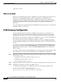
Where to Go Next 5-12
H.323 Gateway Configuration
5-12
Cisco Catalyst 4000 Access Gateway Module Installation and Configuration Note
OL-3008-01
v
Contents
EFT DRAFT - CISCO CONFIDENTIAL
Configuring T1-CAS Analog Emulation (H.323) 5-14
Managing Input Gain for Cisco IP Voice Applications
FXS Emulation Example 5-16
FXO Emulation Example 5-16
E&M Emulation Example 5-17
5-15
ISDN BRI Configuration (H.323) 5-17
Configuring ISDN BRI Lines 5-18
ISDN BRI Provisioning by Switch Type 5-18
Defining ISDN Service Profile Identifiers 5-20
BRI Direct-Inward Dialing Configuration 5-21
Gateway 1 Configuration 5-21
Gateway 2 Configuration 5-22
T1/E1 Configuration (H.323) 5-22
Configuring T1 Interfaces 5-22
T1/PRI Configuration Example 5-23
Configuring E1 Interfaces 5-23
E1/PRI Configuration Example 5-24
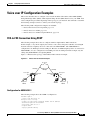
Voice over IP Configuration Examples 5-25
FXS-to-FXS Connection Using RSVP 5-25
Configuration for AGM AGLB-1 5-25
Configuration for AGM AGLB-2 5-26
FXO Connection to PSTN 5-27
AGM SJ Configuration 5-27
AGM SLC Configuration 5-27
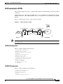
FXO Connection to PSTN Using PLAR Mode
AGM SJ Configuration 5-28
AGM SLC Configuration 5-29
CHAPTER
6
5-28
Configuring the 8-Port and 16-Port FXS RJ-21 Modules
About the 8-Port RJ-21 FXS Module
6-1
6-1
8-Port RJ-21 FXS Module User Interface Conventions
6-1
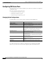
Configuring FXS Voice Ports 6-2
Changing Default Configurations 6-2
Validating the Configuration 6-3
Troubleshooting the Configuration 6-4
Fine-Tuning FXS Voice Ports
Activating the Voice Port
Sample Configuration
6-4
6-6
6-6
Cisco Catalyst 4000 Access Gateway Module Installation and Configuration Note
vi
OL-3008-01
Contents
EFT DRAFT - CISCO CONFIDENTIAL
CHAPTER
7
Configuring Encryption Services
7-1
About the Encryption Service Adapter
7-1
Configuring the Encryption Service Adapter 7-1
Configure the T1 Channel Group 7-2
Configure the Internet Key Exchange Security Protocol 7-3
Configuring IPSec Network Security 7-3
Configure Encryption on the T1 Channel Group Serial Interface
Verifying the Configuration
7-6
Sample Configurations 7-7
Encrypting Traffic Between Two Networks 7-7
Configuration File for the Public Gateway 7-7
Configuration File for the Private Gateway 7-8
Exchanging Encrypted Data Through an IPSec Tunnel
Configuration File for Peer 1 7-10
Configuration File for Peer 2 7-12
CHAPTER
8
Configuring the DSP Farm
7-6
7-10
8-1
About the DSP Farm 8-1
VoIP Gateway Mode 8-1
IP Telephony Gateway Mode 8-2
Conferencing Service 8-3
Transcoding Service 8-4
Configuring IP Telephony Gateway Mode 8-5
Enabling IP Telephony Gateway Mode 8-5
Enabling IP Telephony Conferencing Service 8-5
Enabling IP Telephony Transcoding Service 8-5
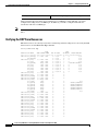
Verifying the DSP Farm Resources 8-6
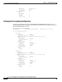
Verifying the Conferencing Configuration 8-7
Verifying the Transcoding Configuration 8-8
Returning to the VoIP Gateway Mode 8-9
Troubleshooting the AGM 8-9
Troubleshooting Diagnostics 8-9
Troubleshooting Controller 8-10
Troubleshooting Hardware 8-13
Troubleshooting TDM 8-13
Troubleshooting DSP 8-14
Cisco Catalyst 4000 Access Gateway Module Installation and Configuration Note
OL-3008-01
vii
Contents
EFT DRAFT - CISCO CONFIDENTIAL
APPENDIX
A
Identifying Hardware Problems with the ROM Monitor
Entering ROM Monitor Mode
Configuring for Autoboot
A-1
A-1
A-2
ROM Monitor Commands A-3
ROM Monitor Syntax Conventions A-3
Command Descriptions A-3
General Use Commands A-3
Debugging Commands A-6
Cookie Commands A-7
Configuration Register Command A-10
Modifying the Configuration Register from the Operating System Software
Boot and System Image Recovery Commands A-11
A-11
Upgrading the ROM Monitor A-13
Upgrading the ROM Monitor from IOS CLI A-13
Upgrading the ROM Monitor from ROMMON A-13
APPENDIX
B
Using Loss Plan Defaults
B-1
Default Loss and Gain Values
Transmission Loss Plan
APPENDIX
C
B-1
B-1
Connector and Cable Specifications
Console Connector Pinouts
Management Port Pinouts
C-1
C-1
C-1
8-Port RJ21 FXS Module Connector Pinouts
C-2
Cable and Adapter Specifications C-3
Crossover and Straight-Through Cable Pinouts
Rollover Cable and Adapter Pinouts C-3
Identifying a Rollover Cable C-3
Connecting to a PC C-4
Connecting to a Terminal C-4
C-3
Cisco Catalyst 4000 Access Gateway Module Installation and Configuration Note
viii
OL-3008-01
Preface
This preface describes who should read the Cisco Catalyst 4000 Access Gateway Module Installation
and Configuration Note, how it is organized and its document conventions, where to find
Cisco Catalyst 4000 Access Gateway Module (AGM) related information, and how to obtain technical
assistance.
Audience
This publication is intended for experienced network administrators who are responsible for installing
the AGM.
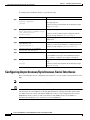
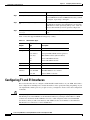
Organization
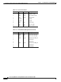
The following table describes the major sections of this publication:
Chapter
Title
Description
Chapter 1
Overview
Provides a overview of the AGM system, features,
and applications.
Chapter 2
Installing the Access Gateway Module
Describes how to install the AGM on the switch
and the interface modules on the AGM.
Chapter 3
Configuring the AGM for the First Time
Describes how to configure the AGM for the first
time.
Chapter 4
Configuring the Data Interfaces
Describes how to configure the data interfaces.
Chapter 5
Configuring the Voice Interfaces
Describes how to configure the voice interfaces.
Chapter 6
Configuring the 8-Port and 16-Port FXS RJ-21 Modules Describes how to configure the 8-port or 16-port
FXS module for analog phones and fax relay.
Chapter 7
Configuring Encryption Services
Describes how to configure the ESA
Chapter 8
Configuring the DSP Farm
Describes how to configure the DSP services.
Appendix A
Identifying Hardware Problems with the ROM Monitor Describes how to use the ROM monitor bootstrap
program.
Cisco Catalyst 4000 Access Gateway Module Installation and Configuration Note
OL-3008-01
ix
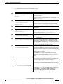
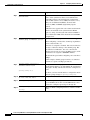
Conventions
Conventions
Chapter
Title
Description (continued)
Appendix B
Using Loss Plan Defaults
Describes how to use the defaults.
Appendix C
Connector and Cable Specifications
Describes the ports, cables and adapters that you
use to connect the switch to other devices.
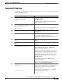
Conventions
This publication uses the following conventions:
Convention
Description
boldface font
Commands and keywords are in boldface.
italic font
Command arguments for which you supply values are in
italic.
[ ]
Command elements in square brackets are optional.
{x | y | z}
Alternative command keywords are grouped in braces
and separated by vertical bars.
[x | y | z]
Optional alternative command keywords are grouped in
brackets and separated by vertical bars.
string
A nonquoted set of characters. Do not use quotation
marks around the command string or the string will
include the quotation marks.
screen
font
boldface screen
Terminal sessions and information the system displays
are in screen font.
Information you must enter is in boldface
screen
font.
font
italic screen font
Arguments for which you supply values are in italic
screen font.
This pointer highlights an important line of text
in an example.
Ctrl
Ctrl represents the Control key on your keyboard. For
example, the key combination Ctrl-D in a screen display
means that you should hold down the Control key while
you press the D key.
< >
Nonprinting characters, such as passwords, are in angle
brackets.
Cisco Catalyst 4000 Access Gateway Module Installation and Configuration Note
x
OL-3008-01
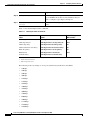
Safety Overview
Safety Overview
Notes use the following conventions:
Note
Means reader take note. Notes contain helpful suggestions or references to material not covered in the
publication.
Cautions use the following conventions:
Caution
Means reader be careful. In this situation, you might do something that could result in equipment
damage or loss of data.
Safety Overview
Safety warnings appear throughout this publication in procedures that, if performed incorrectly, can
harm you. A warning symbol precedes each warning statement.
Warning
This warning symbol means danger. You are in a situation that could cause
bodily injury. Before you work on any equipment, be aware of the hazards
involved with electrical circuitry and be familiar with standard practices for
preventing accidents. To see translations of the warnings that appear in this
publication, refer to the Regulatory Compliance and Safety Information
document that accompanied this device.
Waarschuwing
Dit waarschuwingssymbool betekent gevaar. U verkeert in een situatie die
lichamelijk letsel kan veroorzaken. Voordat u aan enige apparatuur gaat
werken, dient u zich bewust te zijn van de bij elektrische schakelingen
betrokken risico’s en dient u op de hoogte te zijn van standaard maatregelen
om ongelukken te voorkomen. (Voor vertalingen van de waarschuwingen die
in deze publicatie verschijnen, kunt u het aanhangsel “Translated Safety
Warnings” (Vertalingen van veiligheidsvoorschriften) raadplegen.)
Varoitus
Attention
Tämä varoitusmerkki merkitsee vaaraa. Olet tilanteessa, joka voi johtaa
ruumiinvammaan. Ennen kuin työskentelet minkään laitteiston parissa, ota
selvää sähkökytkentöihin liittyvistä vaaroista ja tavanomaisista
onnettomuuksien ehkäisykeinoista. (Tässä julkaisussa esiintyvien
varoitusten käännökset löydät liitteestä "Translated Safety Warnings"
(käännetyt turvallisuutta koskevat varoitukset).)
Ce symbole d’avertissement indique un danger. Vous vous trouvez dans une
situation pouvant entraîner des blessures. Avant d’accéder à cet équipement,
soyez conscient des dangers posés par les circuits électriques et
familiarisez-vous avec les procédures courantes de prévention des
accidents. Pour obtenir les traductions des mises en garde figurant dans cette
publication, veuillez consulter l’annexe intitulée « Translated Safety
Warnings » (Traduction des avis de sécurité).
Installation and Configuration Note for Cisco Catalyst 4000 Access Gateway Module
OL-3008-01
xi
Related Documentation
Related Documentation
Warnung
Dieses Warnsymbol bedeutet Gefahr. Sie befinden sich in einer Situation, die
zu einer Körperverletzung führen könnte. Bevor Sie mit der Arbeit an
irgendeinem Gerät beginnen, seien Sie sich der mit elektrischen
Stromkreisen verbundenen Gefahren und der Standardpraktiken zur
Vermeidung von Unfällen bewußt. (Übersetzungen der in dieser
Veröffentlichung enthaltenen Warnhinweise finden Sie im Anhang mit dem
Titel “Translated Safety Warnings” (Übersetzung der Warnhinweise).)
Avvertenza
Questo simbolo di avvertenza indica un pericolo. Si è in una situazione che
può causare infortuni. Prima di lavorare su qualsiasi apparecchiatura,
occorre conoscere i pericoli relativi ai circuiti elettrici ed essere al corrente
delle pratiche standard per la prevenzione di incidenti. La traduzione delle
avvertenze riportate in questa pubblicazione si trova nell’appendice,
“Translated Safety Warnings” (Traduzione delle avvertenze di sicurezza).
Advarsel
Dette varselsymbolet betyr fare. Du befinner deg i en situasjon som kan føre
til personskade. Før du utfører arbeid på utstyr, må du være oppmerksom på de
faremomentene som elektriske kretser innebærer, samt gjøre deg kjent med
vanlig praksis når det gjelder å unngå ulykker. (Hvis du vil se oversettelser av
de advarslene som finnes i denne publikasjonen, kan du se i vedlegget
"Translated Safety Warnings" [Oversatte sikkerhetsadvarsler].)
Aviso
Este símbolo de aviso indica perigo. Encontra-se numa situação que lhe
poderá causar danos fisicos. Antes de começar a trabalhar com qualquer
equipamento, familiarize-se com os perigos relacionados com circuitos
eléctricos, e com quaisquer práticas comuns que possam prevenir possíveis
acidentes. (Para ver as traduções dos avisos que constam desta publicação,
consulte o apêndice “Translated Safety Warnings” - “Traduções dos Avisos
de Segurança”).
Advertencia
Varning!
Este símbolo de aviso significa peligro. Existe riesgo para su integridad
física. Antes de manipular cualquier equipo, considerar los riesgos que
entraña la corriente eléctrica y familiarizarse con los procedimientos
estándar de prevención de accidentes. (Para ver traducciones de las
advertencias que aparecen en esta publicación, consultar el apéndice
titulado “Translated Safety Warnings.”)
Denna varningssymbol signalerar fara. Du befinner dig i en situation som kan
leda till personskada. Innan du utför arbete på någon utrustning måste du vara
medveten om farorna med elkretsar och känna till vanligt förfarande för att
förebygga skador. (Se förklaringar av de varningar som förekommer i denna
publikation i appendix "Translated Safety Warnings" [Översatta
säkerhetsvarningar].)
Related Documentation
The following publications are available for the Catalyst 4000 family switches:
•
Catalyst 4000 Family Module Installation Guide
•
Catalyst 4500 Series Installation Guide
•
Catalyst 4000 Series Installation Guide
Cisco Catalyst 4000 Access Gateway Module Installation and Configuration Note
xii
OL-3008-01
Obtaining Documentation
Obtaining Documentation
•
Catalyst 3620 Installation and Configuration Guide
•
Catalyst 3200 Installation and Configuration Guide
•
Quick Start Guide Cisco 2600 Series Cabling and Setup
•
Cisco 2600 Series Power Supply Configuration Guide
•
Quick Software Configuration—Catalyst 4000 Family, Catalyst 29266 Series, Catalyst 29486, and
Catalyst 2908G Switches
•
System Message Guide—Catalyst 4000 Family, Catalyst 2948G, and Catalyst 2980G Switches
•
Command Reference—Catalyst 4000 Family, Catalyst 2980G, and Catalyst 2948G
•
Software Configuration Guide—Catalyst 4000 Family, Catalyst 2948G, Catalyst 2980G
•
Site Preparation and Safety Guide
•
Cisco IOS Configuration Guides and Command References—Use these publications to help you
configure the Cisco IOS software.
•
More information about MIBs can be found at the following URL:
http://www.cisco.com/public/sw-center/netmgmt/cmtk/mibs.shtml
Obtaining Documentation
The following sections explain how to obtain documentation from Cisco Systems.
World Wide Web
You can access the most current Cisco documentation on the World Wide Web at the following URL:
http://www.cisco.com
Translated documentation is available at the following URL:
http://www.cisco.com/public/countries_languages.shtml
Documentation CD-ROM
Cisco documentation and additional literature are available in a Cisco Documentation CD-ROM
package, which is shipped with your product. The Documentation CD-ROM is updated monthly and may
be more current than printed documentation. The CD-ROM package is available as a single unit or
through an annual subscription.
Ordering Documentation
Cisco documentation is available in the following ways:
•
Registered Cisco Direct Customers can order Cisco product documentation from the Networking
Products MarketPlace:
http://www.cisco.com/cgi-bin/order/order_root.pl
Installation and Configuration Note for Cisco Catalyst 4000 Access Gateway Module
OL-3008-01
xiii
Documentation Feedback
Obtaining Technical Assistance
•
Registered Cisco.com users can order the Documentation CD-ROM through the online Subscription
Store:
http://www.cisco.com/go/subscription
•
Nonregistered Cisco.com users can order documentation through a local account representative by
calling Cisco corporate headquarters (California, USA) at 408 526-7208 or, elsewhere in North
America, by calling 800 553-NETS (6387).
Documentation Feedback
If you are reading Cisco product documentation on Cisco.com, you can submit technical comments
electronically. Click Leave Feedback at the bottom of the Cisco Documentation home page. After you
complete the form, print it out and fax it to Cisco at 408 527-0730.
You can e-mail your comments to [email protected].
To submit your comments by mail, use the response card behind the front cover of your document, or
write to the following address:
Cisco Systems
Attn: Document Resource Connection
170 West Tasman Drive
San Jose, CA 95134-9883
We appreciate your comments.
Obtaining Technical Assistance
Cisco provides Cisco.com as a starting point for all technical assistance. Customers and partners can
obtain documentation, troubleshooting tips, and sample configurations from online tools by using the
Cisco Technical Assistance Center (TAC) Web Site. Cisco.com registered users have complete access
to the technical support resources on the Cisco TAC Web Site.
Cisco.com
Cisco.com is the foundation of a suite of interactive, networked services that provides immediate, open
access to Cisco information, networking solutions, services, programs, and resources at any time, from
anywhere in the world.
Cisco.com is a highly integrated Internet application and a powerful, easy-to-use tool that provides a
broad range of features and services to help you to
•
Streamline business processes and improve productivity
•
Resolve technical issues with online support
•
Download and test software packages
•
Order Cisco learning materials and merchandise
•
Register for online skill assessment, training, and certification programs
You can self-register on Cisco.com to obtain customized information and service. To access Cisco.com,
go to the following URL:
http://www.cisco.com
Cisco Catalyst 4000 Access Gateway Module Installation and Configuration Note
xiv
OL-3008-01
Technical Assistance Center
Obtaining Technical Assistance
Technical Assistance Center
The Cisco TAC is available to all customers who need technical assistance with a Cisco product,
technology, or solution. Two types of support are available through the Cisco TAC: the Cisco TAC
Web Site and the Cisco TAC Escalation Center.
Inquiries to Cisco TAC are categorized according to the urgency of the issue:
•
Priority level 4 (P4)—You need information or assistance concerning Cisco product capabilities,
product installation, or basic product configuration.
•
Priority level 3 (P3)—Your network performance is degraded. Network functionality is noticeably
impaired, but most business operations continue.
•
Priority level 2 (P2)—Your production network is severely degraded, affecting significant aspects
of business operations. No workaround is available.
•
Priority level 1 (P1)—Your production network is down, and a critical impact to business operations
will occur if service is not restored quickly. No workaround is available.
Which Cisco TAC resource you choose is based on the priority of the problem and the conditions of
service contracts, when applicable.
Cisco TAC Web Site
The Cisco TAC Web Site allows you to resolve P3 and P4 issues yourself, saving both cost and time.
The site provides around-the-clock access to online tools, knowledge bases, and software. To access the
Cisco TAC Web Site, go to the following URL:
http://www.cisco.com/tac
All customers, partners, and resellers who have a valid Cisco services contract have complete access to
the technical support resources on the Cisco TAC Web Site. The Cisco TAC Web Site requires a
Cisco.com login ID and password. If you have a valid service contract but do not have a login ID or
password, go to the following URL to register:
http://www.cisco.com/register/
If you cannot resolve your technical issues by using the Cisco TAC Web Site, and you are a Cisco.com
registered user, you can open a case online by using the TAC Case Open tool at the following URL:
http://www.cisco.com/tac/caseopen
If you have Internet access, it is recommended that you open P3 and P4 cases through the Cisco TAC
Web Site.
Cisco TAC Escalation Center
The Cisco TAC Escalation Center addresses issues that are classified as priority level 1 or priority
level 2; these classifications are assigned when severe network degradation significantly impacts
business operations. When you contact the TAC Escalation Center with a P1 or P2 problem, a Cisco TAC
engineer will automatically open a case.
To obtain a directory of toll-free Cisco TAC telephone numbers for your country, go to the following
URL:
http://www.cisco.com/warp/public/687/Directory/DirTAC.shtml
Installation and Configuration Note for Cisco Catalyst 4000 Access Gateway Module
OL-3008-01
xv
Technical Assistance Center
Obtaining Technical Assistance
•
Before calling, please check with your network operations center to determine the level of Cisco
support services to which your company is entitled; for example, SMARTnet, SMARTnet Onsite,
or Network Supported Accounts (NSA). In addition, please have available your service agreement
number and your product serial number.
Cisco Catalyst 4000 Access Gateway Module Installation and Configuration Note
xvi
OL-3008-01
C H A P T E R
1
Overview
This chapter provides an overview of the Cisco Catalyst 4000 Access Gateway Module (AGM) and
describes its applications, features, and supported modules.
This chapter contains these major sections:
•
AGM Features, page 1-1
•
Hardware Features, page 1-4
•
Software Features, page 1-8
AGM Features
The AGM provides integrated telephony and routing capabilities for the Catalyst 4000 family switches
with the following system features:
•
Voice gateway to the Public Switched Telephone Network (PSTN) with a choice of digital (T1, E1,
ISDN Primary Rate Interface (PRI), Basic Rate Interface (BRI) or analog foreign exchange office
(FXO)) interfaces. These interfaces can be used to connect to a variety of PBX/PABXs.
•
Analog voice gateway with foreign exchange station (FXS) interfaces for fax machines,
speakerphones, modems, and analog phones.
•
Advanced telephony services, including voice conferencing and transcoding for analog phones, IP
phones, and Cisco Survivable Remote Site Telephony (SRS Telephony) for robust and resilient call
control.
•
Cisco IOS routing, including support for IP, IPv6, IPX, and System Network Architecture (SNA),
WCCPv2, and NAT.
•
Secure IP WAN connectivity with firewall, intrusion detection, and hardware-based encryption.
•
Centralized IP Telephony features through Cisco CallManager, with features to Enterprise branch
offices via Cisco Survivable Remote Site Telephony (SRS Telephony) and IOS Telephony Services
(ITS).
AGM Applications
The AGM is typically used in IP telephony campus and large branch office applications. These
applications are described in this section.
Cisco Catalyst 4000 Access Gateway Module Installation and Configuration Note
OL-3008-01
1-1
Chapter 1
Overview
AGM Features
IP Telephony Campus
The Catalyst 4000 family switches support inline power for IP telephones that are usually deployed in
wiring or distribution closets at a campus. These switches can be equipped with the AGM to support the
IP telephony campus application.
Figure 1-1 Shows the AGM deployed in an IP telephony campus application.
Figure 1-1
IP Telephony Campus Application of Catalyst 4000 Family Switches with AGMs
Fax
PSTN
V
Wiring
closet
V
Core
switch
V
V
V
Distribution
switches
Catalyst 4000/4500
Series
with AGM
IP WAN
V
WAN router
and Voice
gateway
85427
Desktop with
IP Phone
and PC
Large Branch Office
The AGM can be deployed at large branches with up to 192 users as an integrated voice gateway and
WAN router. In this deployment, the Catalyst 4000 family switches can be equipped with the AGM to
support the large branch office application. This application uses all the features listed in the AGM
Features section.
Cisco Catalyst 4000 Access Gateway Module Installation and Configuration Note
1-2
OL-3008-01
Chapter 1
Overview
AGM Features
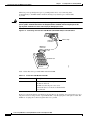
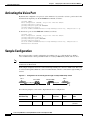
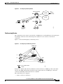
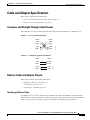
Figure 1-2 Shows the AGM deployed in a large branch office application with up to 192 users.
Figure 1-2
Large Branch Office Application of a Catalyst 4000 Family Switch with an AGM
Fax
Catalyst 4000/4500 Series
with AGM
V
PSTN
T1/E1/PRI/BRI/FXO
85428
IP WAN
Catalyst 4000 Switch Integration
The AGM is a physically integrated but functionally independent Cisco IOS router inside the switch. It
is connected to the switch by a Gigabit Ethernet 802.1Q trunk on the backplane that supports multiple
VLANs. It can be used with the Catalyst operating system on the Supervisor II or with Cisco IOS on
Supervisor III and IV, but it must be configured separately from the Supervisor Engine.
The AGM can be configured and monitored from the following locations:
•
the console port on the AGM
•
the management port (10/100 ethernet) on the AGM
•
the console or management port on the Supervisor Engine (with the session or attach module
command)
Cisco Catalyst 4000 Access Gateway Module Installation and Configuration Note
OL-3008-01
1-3
Chapter 1
Overview
Hardware Features
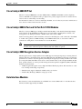
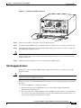
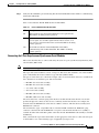
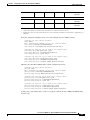
Figure 1-3 shows the front-panel of the AGM. You can see the console port on the lower left and the Fast
Ethernet port immediately to the right of the console port.
Figure 1-3
Access Gateway Module Fast Ethernet and Console Ports
Two VIC/WIC slots
FlexSlot
high density analog
One VIC slot
WS-X4604-GWY
WIC
2A/S
CONSOLE
WAN GATEWAY
STATUS
VIC
2FXS
VWIC
2MFT-T1-D1
0
1
SEE MANUAL BEFORE INSTALLATION
CONN
CTRLR T1 1
CTRLR T1 0
SEE
MANUAL
BEFORE
INSTALLATION
0
1
2
3
4
5
6
7
WS-U4604-8FXS
VWIC 1
10/100MGT
Console port
0
1
DSP BANK
READY
2
ACTIVE
FLEXSLOT 4
VWIC 2
73355
CONN
VIC 3
3
FLEXSLOT 4 STATUS
One system and eight DSP
status LEDs
10/100 BaseT Ethernet
management port
The AGM ports are named according to their positions in their respective slots. From the left, the slots
are numbered 1, 2, 3, and 4. Slots 1 and 2 are for VWICs, slot 3 is for VICs, and slot 4 is for multiflex
modules.
A VWIC, VIC, or WIC can have one or more ports, so ports on the interface modules are sequentially
numbered starting with 0 for the right-most port and increasing by one in the right to left direction.
Note
The inverse port-numbering order is inherited from existing VWIC, VIC, and WIC port-numbering
conventions.
Hardware Features
The AGM supports the following hardware features:
•
A DSP bank with 24 DSPs (4 SIMMs with 6 DSPs each) supporting a maximum of 96 voice
channels.
•
Two voice or WAN interface module (VWIC) slots—Support VWICs, voice interface modules
(VICs), and WAN interface modules (WICs).
•
One VIC slot—Supports the same VWICs and VICs as slots 1 and 2, but does not support WICs.
•
One multiflex slot—Reserved for the 8-Port and 16-Port RJ21 FXS modules.
•
One Fast Ethernet port—Reserved for management purposes only. It does not support data
switching or routing.
•
One console port—For configuration purposes, you can connect via terminal or modem.
•
One Gigabit Ethernet backbone interface—Standard IOS Gigabit Ethernet interface with the
following exceptions:
– Supports 802.1q instead of ISL
– Cannot be shut down without losing communication with the Supervisor Engine
•
Encryption Service Adapter (ESA)—High-performance data encryption module to offload some of
the encryption processing from the AGM main processor and to improve performance.
Cisco Catalyst 4000 Access Gateway Module Installation and Configuration Note
1-4
OL-3008-01
Chapter 1
Overview
Hardware Features
Cisco Catalyst 4000 DSP Set
The Cisco Catalyst 4000 DSP set for the AGM includes 4 SIMMs with 6 DSPs each for telephony
services. The DSPs are required for analog or digital voice gateway support as well as for advanced voice
services such as conferencing or transcoding.
For information on the voice services enabled by the DSPs, see Voice Gateway Features and Advanced
Voice Services in the Software Features section.
Cisco Catalyst 4000 8-Port and 16-Port RJ-21 FXS Modules
The Cisco Catalyst 4000 8-port and 16-port RJ-21 FXS modules can be installed in the high density
analog flexslot on the AGM. By providing services to fax machines, speakerphones, modems, and
analog phones, the FXS ports emulate a PSTN central-office (CO) or PBX.
Calls from analog phones and fax machines connected to the FXS ports can be connected to the PSTN
or another analog phone via TDM switching on the AGM module itself, or converted to VoIP for
connection to an IP phone or for transmission across the IP WAN.
Note
The FXS interfaces are separated into power domains to provide power protection between
domains and to ensure that ports not directly affected continue to operate.
Cisco Catalyst 4000 Encryption Service Adapter
The Encryption Service Adapter (ESA) for the AGM supports an integrated package of routing, firewall,
intrusion detection, and virtual private network (VPN) functions. The ESA provides up to ten times the
performance of software-only encryption by offloading the encryption processing from the router central
processing unit (CPU). The ESA can be used to connect branch offices to the enterprise IP WAN, mobile
users, partner extranets, or service provider managed customer premises equipment (CPE). Other ESA
hardware features include:
•
3 DES encryption/decryption on two duplex E1 links with 64-byte packets. This translates to a data
rate of 8 mbps and 15 kbps, respectively
•
Simultaneously support 10 tunnels and 60 security associations
•
4 Internet Key Exchange (IKE) SA setups per second
Data Interface Modules
Data interfaces can be installed in the two VIC/WIC slots on the AGM. Table 1-1 describes the data
interface modules supported by the AGM.
Cisco Catalyst 4000 Access Gateway Module Installation and Configuration Note
OL-3008-01
1-5
Chapter 1
Overview
Hardware Features
Table 1-1
Data Interface Modules
Module
Description
WIC-2A/S
Dual asynchronous or synchronous serial ports
WIC-2T
Two-port serial WAN interface module
Note
WIC-1T is not supported
WIC-1DSU-T1
One-port T1/ fractional T1 with CSU/DSU
WIC-1DSU-56K4
One-port four-wire 56 or 64 kbps CSU/DSU
VWIC-1MFT-T1
One-port T1/ fractional T1 multiflex trunk with
CSU/DSU
VWIC-2MFT-T1
Two-port T1/ fractional T1 multiflex trunk with
CSU/DSU
VWIC-2MFT-T1- DI
Dual-port T1/fractional T1 multiflex trunk with
CSU/DSU (Drop and insert is not supported)
VWIC-1MFT-E1
One-port E1/fractional T1 multiflex trunk with DSU
VWIC-2MFT-E1- DI
Dual-port E1/fractional T1 multiflex trunk with DSU
VIC-2BRI-S/T- TE
User side S/T only, no 144 kbps and 80 kbps leased
line
Note
The VIC-2BRI is used for BRI data
connectivity and can be installed in any of
the VIC slots.
Note
DSPs are required for voice support on the VWICs.
Note
VWICs can be used in any WIC or VIC slot.
Note
Primary Rate Interface (PRI) dial-up data connections are not supported at this time.
Voice Interface Modules
There are two types of voice interface modules supported by the AGM:
•
VIC modules can be installed in the VIC slot or the two VIC/WIC slots on the AGM
•
VWIC modules can be installed in any of the VIC slots on the AGM
Table 1-2 describes the voice interface modules supported by the AGM.
Cisco Catalyst 4000 Access Gateway Module Installation and Configuration Note
1-6
OL-3008-01
Chapter 1
Overview
Hardware Features
Table 1-2
Voice Interface Modules
Module
Description
VIC-2FXS
Two-port FXS voice/fax interface module
VIC-2FXO
Two-port FXO voice/fax interface module (North
American version)
VIC-2FXO-EU
Two-port FXO voice/fax interface module (European
version)
VIC-2BRI-S/T-TE
Two-port BRI S/T terminal equipment voice/fax
interface module (also supports data)
VWIC-1MFT-T1
One-port T1/fractional T1 multiflex trunk with
CSU/DSU
VWIC-2MFT-T1
Dual-port T1/fractional T1 multiflex trunk with
CSU/DSU
VWIC-2MFT-T1-DI
Dual-port T1/fractional T1multiflex trunk with
CSU/DSU, no DI
VWIC-1MFT-E1
One-port E1/fractional T1 multiflex trunk with DSU
VWIC-2MFT-E1
Dual-port E1/fractional T1multiflex trunk with DSU
VWIC-2MFT-E1-DI
Dual-port E1/fractional T1 multiflex trunk with DSU
and no DI
Signaling Support on AGM
Table 1-3 describes the signaling supported by the AGM.
Table 1-3
Signaling Supported by the AGM
Signaling
T1-CAS/PRI
E1-CAS/PRI
E1-R2
BRI
H 323
Yes
Yes
Yes
Yes
MGCP
Yes
E1PRI Only
No
No
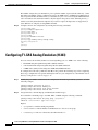
Switch-Type Support on AGM
Table 1-4 describes the switch-types supported by the AGM.
t
Table 1-4
Switch-types supported by the AGM.
Signaling
T1-CAS/PRI
E1-CAS/PRI
E1-R2
BRI
QSIG
H 323/MGCP
Yes
Yes
H 323/MGCP
NI
H 323/MGCP
H 323/MGCP
H 323/MGCP
H 323/MGCP
5ESS
H 323/MGCP
H 323/MGCP
H 323/MGCP
H 323/MGCP
4ESS
H 323/MGCP
H 323/MGCP
H 323/MGCP
H 323/MGCP
DMS100/250
H 323/MGCP
H 323/MGCP
H 323/MGCP
H 323/MGCP
EURO
H 323/MGCP
NA
H 323/MGCP
H 323/MGCP
Cisco Catalyst 4000 Access Gateway Module Installation and Configuration Note
OL-3008-01
1-7
Chapter 1
Overview
Software Features
Software Features
This section describes the AGM software features.
Telephony Call Control
The AGM supports several options for telephony call control:
•
Cisco Call Manager (CCM) can be used for centralized call control for numerous VoIP gateways,
including the AGM, at campus and branch sites. The AGM supports both MGCP and H.323v2
interfaces to the CCM.
•
SRST is an IOS-based backup for the CCM that resides on the AGM itself. SRST automatically
takes over call control if connectivity to the CCM is lost.
•
ITS software can be used for distributed call control.
Voice Gateway Features
The AGM can provide voice gateway support for up to 96 voice channels, or up to 48 channels if
conferencing or transcoding are enabled. The AGM supports the following voice gateway services:
•
VoIP encapsulation—10, 20, 30, 40, 50, and 60 msec packet sizes
•
Voice Compression—G.711 and G.729a encoding
•
Fax Support—Cisco Fax Relay and G.711 Fax Passthrough support
•
Modem Support—G.711 Modem Passthrough support
•
IP Header Compression—CRTP
•
Echo Cancellation—8 to 64 msec echo cancellation support, depending on interface type
•
Signaling Types—T1 channel-associated signaling (CAS), ISDN Primary Rate Interface (PRI),
Basic Rate Interface (BRI)
Advanced Voice Services
The AGM supports advanced voice services such as conferencing and transcoding:
•
Conferencing—when conferencing is enabled, 4 DSPs are allocated to conferencing. Each DSP
supports 1 conference x 6 parties or 2 conferences x 3 parties. The AGM supports both meet-me and
ad-hoc conference modes.
•
Transcoding—when transcoding is enabled, 8 DSPs are allocated to conferencing. Each DSP
transcodes 2 full duplex voice channels between G.711 and G.729a.
Routing Services
The AGM supports the following Cisco IOS routing services:
•
Routing Protocols—IP (v4), IPv6, IPX, SNA
•
Routing algorithms—OSPF, BGP, and more
Cisco Catalyst 4000 Access Gateway Module Installation and Configuration Note
1-8
OL-3008-01
Chapter 1
Overview
Software Features
•
NAT
•
WCCP v2
•
10 kpps 802.1q inter-VLAN routing
The link to Feature Navigator is:
http://www.cisco.com/cgi-bin/Support/FeatureNav/FN.pl
Security
The AGM provides the same security to voice and video networks that is available for data networks.
The AGM supports the optional Cisco IOS Software Firewall Feature Set, Cisco IOS Intrusion Detection
Service (IDS), IP Security (IPsec) with data encryption standard (DES), and Triple DES (3DES).
Hardware encryption using the onboard encryption accelerator provides significantly higher
performance than software-based encryption, and frees processor capacity for other services.
The following encryption features are supported:
•
56-bit DES encryption using Cipher Block Chaining (CBC) mode
•
168-bit 3DES encryption using CBC mode
•
MD5 and SHA-1 hashing, including support for the HMAC transform with IPSec AH and ESP
•
Support for Diffie-Hellman key exchange
•
RSA and DSA public key signature and verification (when implemented by IOS IPSec Crypto
Engine)
QoS
The AGM can identify user applications, such as voice or multicast video, and classify traffic with the
appropriate priority levels. QoS policies are enforced using Layer 2 and 3 information such as 802.1p
and IP precedence. The AGM queues employ weighted random early detection (WRED) and weighted
round-robin (WRR) to ensure that QoS is maintained as packets traverse the network.
To ease the deployment of QoS, the AGM supports Cisco QoS Policy Manager (QPM). QPM is a
complete policy management tool that enables provisioning of end-to-end differentiated services across
network infrastructures with converged voice, video, and data applications. The combination of QPM
and CiscoWorks Service Management Solution enables network administrators to adjust service levels
in accordance with defined QoS policies. The end result is network-wide intelligent, and consistent QoS
that enables performance protection for voice applications while reducing costs for growing networks.
Resiliency
The AGM provides the following tools to enhance the resiliency of networks:
•
SRS Telephony provides resiliency for IP phones when they lose connectivity with the Cisco Call
Manager (For complete information on the feature, go to the following url:
http://wwwin.cisco.com/access/mce/solutions/ent/voice/srst/
•
HSRP provides resiliency for IP packets
•
BRI backup provides resiliency for WAN connections
Cisco Catalyst 4000 Access Gateway Module Installation and Configuration Note
OL-3008-01
1-9
Chapter 1
Overview
Software Features
Network Management Support
The AGM supports the following tools for network management:
•
Simple Network Management Protocol (SNMP)
•
CiscoWorks
•
Cisco Voice Manager (CVM)
•
Cisco CallManager
Cisco Catalyst 4000 Access Gateway Module Installation and Configuration Note
1-10
OL-3008-01
C H A P T E R
2
Installing the Access Gateway Module
This chapter describes how to install the Cisco Catalyst 4000 Access Gateway Module (AGM) in a
Catalyst 4000 family switch chassis.
This chapter contains these major sections:
Warning
•
Preparing to Install the AGM, page 2-1
•
Removing Catalyst 4000 Switching Modules (optional), page 2-2
•
Installing the AGM, page 2-3
•
Checking the AGM Operation, page 2-6
•
Installing Voice and WAN Interface Modules, page 2-6
•
Installing Voice and WAN Interface Modules, page 2-6
•
Connecting the Voice and WAN Interface Modules, page 2-8
•
Connecting a Terminal to the Console and Ethernet Management Ports, page 2-25
Before you install, operate, or service the system, read the Site Preparation and Safety Guide. This
guide contains important safety information you should know before working with the system.
Preparing to Install the AGM
You need these tools to install the AGM and the supported interface modules:
Warning
•
Flat-blade screwdriver
•
Number 1 and number 2 Phillips screwdrivers for the captive installation screws on most modules
•
3/16-inch flat-blade screwdriver for the captive installation screws on some modules
•
Antistatic mat or antistatic foam
•
Wrist strap or other grounding device to prevent ESD damage
Only trained and qualified personnel should be allowed to install, replace, or service this
equipment.
Cisco Catalyst 4000 Access Gateway Module Installation and Configuration Note
OL-3008-01
2-1
Chapter 2
Installing the Access Gateway Module
Removing Catalyst 4000 Switching Modules (optional)
Caution
Before you handle switching modules, read the “Preventing Electrostatic Discharge Damage” section
on page 2-2.
You also need an appropriate connecting cable to install and connect your interface module(s). The cable
type required for each module is described in the section for that module.
These items are optional:
•
Synchronous modem, DSU/CSU, or other DCE—Used to connect the WIC-2 A/S to a digital WAN
line.
•
External NT1 ISDN BRI S/T leased-line modules only—Used to connect the VIC-2BRI-S/T-TE to
an ISDN interface.
Preventing Electrostatic Discharge Damage
Electrostatic discharge (ESD) damage, which can occur when electronic cards or components are
improperly handled, results in complete or intermittent failures. Port adapters and processor modules
comprise printed circuit boards that are fixed in metal carriers. Electromagnetic interference (EMI)
shielding and connectors are integral components of the carrier. Although the metal carrier helps to
protect the board from ESD, use a preventive antistatic strap during handling.
Following are guidelines for preventing ESD damage:
Caution
•
Always use an ESD wrist or ankle strap and ensure that it makes good skin contact.
•
Connect the equipment end of the strap to an unfinished chassis surface.
•
When installing a component, use any available ejector levers or captive installation screws to
properly seat the bus connectors in the backplane or midplane. These devices prevent accidental
removal, provide proper grounding for the system, and help to ensure that bus connectors are
properly seated.
•
When removing a component, use any available ejector levers or captive installation screws to
release the bus connectors from the backplane or midplane.
•
Handle carriers by available handles or edges only; avoid touching the printed circuit boards or
connectors.
•
Place a removed board component-side-up on an antistatic surface or in a static shielding container.
If you plan to return the component to the factory, immediately place it in a static shielding
container.
•
Avoid contact between the printed circuit boards and clothing. The wrist strap only protects
components from ESD voltages on the body; ESD voltages on clothing can still cause damage.
Never attempt to remove the printed circuit board from the metal carrier.
Removing Catalyst 4000 Switching Modules (optional)
Caution
To prevent ESD damage, handle switching modules by the carrier edges only. Whenever you handle
switching modules, you should use a wrist strap or other grounding device.
Cisco Catalyst 4000 Access Gateway Module Installation and Configuration Note
2-2
OL-3008-01
Chapter 2
Installing the Access Gateway Module
Installing the AGM
To install the AGM, you might need to remove a switching module from a Catalyst 4000 family switch.
If so, perform these steps:
Step 1
Disconnect any network interface cables attached to the ports on the switching module that you intend
to remove.
Step 2
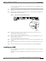
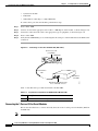
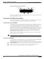
Loosen the captive installation screws, as shown in Figure 2-1. This figure displays the AGM, but the
instructions apply to all the switch modules.
Figure 2-1
Ejector Levers and Captive Installation Screws
WS-X4604-GWY
WIC
2A/S
CONN
WAN GATEWAY
1
VWIC
2MFT-T1-D1
0
SEE MANUAL BEFORE INSTALLATION
CONSOLE
10/100MGT
CTRLR T1 1
CTRLR T1 0
SEE
MANUAL
BEFORE
INSTALLATION
0
1
2
3
4
5
6
7
WS-U4604-8FXS
VWIC 1
0
DSP BANK
READY
1
2
ACTIVE
VWIC 2
VIC 3
FLEXSLOT 4
3
FLEXSLOT 4 STATUS
73351
STATUS
VIC
2FXS
CONN
Ejector lever
Captive
installation
screw
Step 3
Grasp the left and right ejector levers and simultaneously pivot the levers outward to release the
switching module from the backplane connector.
Figure 2-1 shows a close-up of the right ejector lever.
Step 4
Grasp the switching module front panel with one hand and place your other hand under the carrier to
support and guide it out of the slot.
Do not touch the printed circuit boards or connector pins.
Step 5
Carefully pull the switching module straight out of the slot, keeping your other hand under the carrier
to guide it.
Step 6
Place the switching module on an antistatic mat or antistatic foam, or immediately install it in another
slot.
Step 7
If the slot will remain empty, install a switching module filler plate (part number 800-00292-01).
Installing the AGM
All Catalyst 4000 family switching modules are installed in horizontal chassis slots that are numbered
from top to bottom.
You can remove and install the AGM without powering down the switch. This feature is known as hot
swapping.
Cisco Catalyst 4000 Access Gateway Module Installation and Configuration Note
OL-3008-01
2-3
Chapter 2
Installing the Access Gateway Module
Installing the AGM
Caution
To prevent ESD damage, handle the AGM by the carrier edges only. Moreover, you should use a
wrist strap or other grounding device to prevent ESD damage.
To install the AGM, perform these steps:
Step 1
Note
Choose a slot for the new AGM.
The AGM can be inserted into slots 2 or 3 in the Catalyst 4003 switch and slots 2 through 6 in the
Catalyst 4006 switch. In the Catalyst 4003 and Catalyst 4006 switches, slot 1 is reserved for the
supervisor engine.
Ensure that you have enough clearance to accommodate any interface equipment that you will connect
directly to the AGM ports. If possible, place AGMs between empty slots that contain only switching
module filler plates.
Step 2
Loosen the captive installation screws securing the switching module filler plate (or the existing
switching module) to the desired slot.
Step 3
Remove the switching module filler plate (or the existing switching module). Save the switching
module filler plate for future use.
Note
If you are removing an existing switching module, refer to the “Removing Catalyst 4000
Switching Modules (optional)” section on page 2-2.
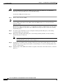
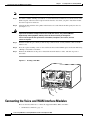
Step 4
To install the new AGM, hold the switching module front panel with one hand, and place your other
hand under the carrier to support the module, as shown in Figure 2-2. Do not touch the printed circuit
boards or connector pins.
Step 5
Align the edges of the AGM carrier with the slot guides on the sides of the switch chassis, as shown in
Figure 2-2.
Cisco Catalyst 4000 Access Gateway Module Installation and Configuration Note
2-4
OL-3008-01
Chapter 2
Installing the Access Gateway Module
Installing the AGM
Figure 2-2
Installing the AGM in the Chassis
Power Supply 1
73352
CAUTION
Power Supply 2
THIS ASSEMBLY
CONTAINS
ELECTROSTATICSENSITIVE DEVICES
0%
100%
WS-X4204
WIC
2A.S
CONN
VIC
2FXS
1
CONN
GATEWAY
SEE MANUAL BEFORE
INSTALLATION
CTRLR T1 1
0
1
2
ACTIVE
CTRLR T1 0
SEE
MANUAL
BEFORE
INSTALLATION
0
1
2
3
4
5
6
7
WS-U4604-8FXS
DSP BANK
READY
VWIC 1
10/100 MGT
AL
LP
CD
VWIC
2MFT-T1-D1
0
CONSOLE
STATUS
VWIC 2
3
VIC 3
FLEXSLOT 4
FLEXSLOT 4
Step 6
Pivot the two module ejector levers out away from the faceplate.
Step 7
Carefully slide the AGM into the slot until the notches on both ejector levers engage the chassis sides.
Step 8
Using the thumb and forefinger of each hand, simultaneously pivot in both ejector levers to fully seat
the AGM in the backplane connector.
Caution
Step 9
Always use the ejector levers when installing or removing the AGM. A module that is partially seated
in the backplane will cause the system to halt and reset. Ensure that the ejectors are locked when the
module is in the slot.
Tighten the captive installation screws on each end of the AGM faceplate.
Hot-Swapping Features
Although you can hot swap the AGM without powering down the switch, you cannot hot swap the
interface modules.
Caution
Hot swapping a VIC, WIC, or VWIC from the AGM could damage the module. Their installation
requires removing the AGM from the chassis.
When you remove or insert the AGM while the switch is powered on and operating, the system does the
following:
1.
Scans the backplane for configuration changes.
2.
Initializes all newly inserted AGM, notes any removed modules, and places them in the
administratively shutdown state.
3.
Places any previously configured interfaces on the AGM back to the state they were in when they
were removed. Any newly inserted interfaces are put in the administratively shutdown state, as if
they were present (but not configured) at boot time.
Cisco Catalyst 4000 Access Gateway Module Installation and Configuration Note
OL-3008-01
2-5
Chapter 2
Installing the Access Gateway Module
Checking the AGM Operation
The system runs diagnostic tests on any new interfaces.
Caution
•
If the test passes, the system is operating normally. If the new AGM is faulty, the system resumes
normal operation but places the new module in the “faulty” state.
•
If the test fails, the system crashes, which usually indicates that the new AGM has a problem and
should be removed.
To avoid erroneous failure messages, allow at least 2 minutes for the system to reinitialize, and note
the current configuration of all interfaces before you remove or insert another AGM.
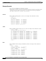
When you hot swap an AGM, the system displays status messages on the console. The following
example shows the messages logged by the system when a gateway module is removed from slot 3:
Console>
1999 Sep
Console>
1999 Sep
Console>
1999 Sep
Console>
(enable)
09 12:23:26 %SYS-5-MOD_REMOVE:Module 3 has been removed
(enable)
09 12:23:44 %SYS-5-MOD_INSERT:Module 3 has been inserted
(enable)
09 12:23:47 %SYS-5-MOD_OK:Module 3 is online
(enable)
If you use the show mod command to query the module before reinstalling a module to replace the
removed one, the system responds, “Module 3 is not installed.” When the module is reinserted, the
system recognizes the module as ready again.
Note
Running the show mod command can take a few minutes.
Checking the AGM Operation
The AGM can take up to two minutes to boot and it does not appear on the supervisor engine console
until IOS is operating. The latter might take up to 10 minutes.
To check the status of the module, perform these steps:
Step 1
Ensure that the LED labeled STATUS is green (indicating the module is operational).
Step 2
When the switch is online, enter the show module command. Verify that the system acknowledges the
new module and that the status of the module is good.
Step 3
If the module is not operational, reseat it. If the module is still not operational, contact your customer
service representative.
Installing Voice and WAN Interface Modules
The AGM has four slots reserved for WAN interface modules (WICs), voice interface modules (VICs),
and T1/E1 multiflex voice/WAN interface modules (VWICs). You can install any combination of VICs,
WICs, and VWICs in slots 1 and 2, but slot 3 accepts only VICs and VWICs. Slot 4 is filled with the
high-density analog module when you first receive the switch.
Cisco Catalyst 4000 Access Gateway Module Installation and Configuration Note
2-6
OL-3008-01
Chapter 2
Installing the Access Gateway Module
Installing Voice and WAN Interface Modules
Note
Caution
VICs, WICs, and VWICs do not support online insertion and removal (hot swapping).
Before inserting a VIC, WIC, or VWIC into the AGM, you must turn off the electrical power by
either powering off the switch or unplugging the AGM from the chassis and disconnecting the
network cables.
Warning
Do not work on the system or connect or disconnect cables during periods of lightning activity.
Warning
This equipment is to be installed and maintained by service personnel only as defined by AS/NZS
3260 Clause 1.2.14.3 Service Personnel.
Warning
Incorrect connection of this or connected equipment to a general purpose outlet could result in a
hazardous situation.
Warning
The telecommunications lines must be disconnected 1) before unplugging the main power
connector and/or 2) while the housing is open.
Warning
Hazardous network voltages are present in WAN ports regardless of whether power to the unit is
OFF or ON. To avoid electric shock, use caution when working near WAN ports. When detaching
cables, detach the end away from the unit first.
Warning
To avoid electric shock, do not connect safety extra-low voltage (SELV) circuits to
telephone-network voltage (TNV) circuits. LAN ports contain SELV circuits, and WAN ports
contain TNV circuits. Some LAN and WAN ports both use RJ-45 connectors. Use caution when
connecting cables.
Warning
Network hazardous voltages are present in the BRI, fractional T1/T1, and Switched 56 cables. If
you detach the cable, detach the end away from the router first to avoid possible electric shock.
Network hazardous voltages are also present in the area of the BRI (RJ-45), fractional T1/T1
(RJ-48C), and Switched 56 (RJ-11 or RJ-48S) ports, regardless of whether power is off or on.
Warning
To reduce the risk of fire, use only No. 26 AWG or larger telecommunication line cord.
To install a VIC/WIC, perform these steps:
Step 1
If the switch is powered on, remove the AGM from the chassis or power off the chassis.
Step 2
Remove all network interface cables, including telephone cables, from the front panel.
Cisco Catalyst 4000 Access Gateway Module Installation and Configuration Note
OL-3008-01
2-7
Chapter 2
Installing the Access Gateway Module
Connecting the Voice and WAN Interface Modules
Note
To channel ESD voltages to ground, do not unplug the power cable.
Step 3
Use either a number 2 Phillips screwdriver or a small flat-blade screwdriver to loosen the screws of the
blank faceplate and remove the faceplate from the interface slot where you plan to install the module.
Save the faceplate for future use.
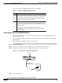
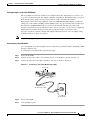
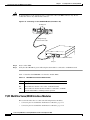
Step 4
Align the module with the cable guides in the interface slot and slide the module gently into the slot.
(See Figure 2-3.)
Warning
Blank faceplates and cover panels serve three important functions: they prevent
exposure to hazardous voltages and currents inside the chassis; they contain EMI that
might disrupt other equipment; and they direct the flow of cooling air through the
chassis. Do not operate the system unless all modules, faceplates, front covers, and rear
covers are in place.
Step 5
Push the module into place until you feel its edge connector mate securely with the connector in the
interface slot.
Step 6
Place the captive mounting screws on the card into the holes in the AGM faceplate and fasten them using
a Phillips or flat-blade screwdriver.
Step 7
Reinsert the AGM, restore the power, reinstall the network interface cables, and turn on power to
the switch.
Figure 2-3
Inserting a VIC/WIC
Power Supply 1
73353
CAUTION
Power Supply 2
THIS ASSEMBLY
CONTAINS
ELECTROSTATICSENSITIVE DEVICES
0%
100%
WS-X4204
WIC
2A.S
CONN
CTRLR T1 1
CONSOLE
DSP BANK
READY
VWIC 1
STATUS
AL
LP
CD
VIC3
2MFT-T1-D1
CONN
GATEWAY
0
10/100 MGT
VIC
VWIC
1
2
ACTIVE
2FXS
2FXS
1
SEE MANUAL BEFORE
INSTALLATION
CTRLR T1 0
SEE
MANUAL
BEFORE
INSTALLATION
0
1
2
3
4
5
6
7
WS-U4604-8FXS
VWIC 2
VIC 3
3
FLEXSLOT 4
0
FLEXSLOT 4
VIC/WIC
Guides
Connecting the Voice and WAN Interface Modules
These sections describe how to connect the supported VWICs, WICs, and VICs:
•
WAN Interface Modules, page 2-9
Cisco Catalyst 4000 Access Gateway Module Installation and Configuration Note
2-8
OL-3008-01
Chapter 2
Installing the Access Gateway Module
Connecting the Voice and WAN Interface Modules
•
Voice Interface Modules, page 2-14
•
T1/E1 Multiflex Voice/WAN Interface Modules, page 2-22
WAN Interface Modules
This section describes the procedures for connecting the following WAN interface modules:
•
Connecting the 1-Port 56/64-kbps DSU/CSU Modules, page 2-9
•
Connecting the 1-Port T1/FT1 DSU/CSU Modules, page 2-10
•
Connecting the 2-Port Asynchronous/Synchronous Serial Modules, page 2-11
•
Connecting the 1-Port and 2-Port Serial Modules, page 2-12
Connecting the 1-Port 56/64-kbps DSU/CSU Modules
This section describes how to connect and verify the status of the 1-port 56/64-kbps Data Service
Unit/Channel Service Unit (DSU/CSU) interface modules (WIC-1DSU-56K).
Use a straight-through RJ-48S-to-RJ-48S or the straight-through RJ-48C-to-RJ-48C cable that shipped
with the AGM.
To connect the 1-port 56/64-kbps DSU/CSU module, perform these steps:
Step 1
Power off the AGM.
Step 2
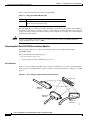
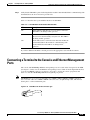
Connect one end of the cable to the 56/64-kbps port of the module, as shown in Figure 2-4.
Step 3
Connect the other end of the cable to the RJ-48S wall jack, as shown in Figure 2-4.
Figure 2-4
Connecting a 56/64-kbps Module (WIC-1DSU-56K)
SEE MANUAL BEFORE INSTALLA
CD
LP
AL
TD
RD
Switched 56/64-kbps port
(RJ-48S)
TION
DSU
56K
H9379
Straight-through
RJ-48S-to-RJ-48S cable
RJ-48S wall jack
Step 4
Power on the AGM.
Step 5
Verify that the CD LED is green, indicating that the internal DSU/CSU is communicating with another
DSU/CSU.
Cisco Catalyst 4000 Access Gateway Module Installation and Configuration Note
OL-3008-01
2-9
Chapter 2
Installing the Access Gateway Module
Connecting the Voice and WAN Interface Modules
Table 2-1 describes the 56/64-kbps WAN interface module LEDs.
Table 2-1
56/64-kbps WAN Interface Module LEDs
LED
Description
TD
Green indicates that data is being transmitted to the DTE interface.
RD
Green indicates that data is being received from the DTE interface.
LP
Yellow indicates that the internal DSU/CSU is in loopback mode.
This LED is off during normal operation.
AL
Yellow indicates that one of these alarm conditions is present: no
receive signal, loss of frame signal from the remote station, or an
out-of-service signal from the remote station. This LED is off during
normal operation.
CD
Green indicates that the internal DSU/CSU in the WIC is
communicating with another DSU/CSU. This LED is off during
normal operation.
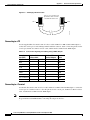
Connecting the 1-Port T1/FT1 DSU/CSU Modules
This section describes how to connect and verify the status of the 1-port T1/FT1 DSU/CSU interface
module (WIC-1DSU-T1).
Use a straight-through RJ-48S-to-RJ-48S or the straight-through RJ-48C-to-RJ-48C cable that shipped
with the AGM.
To connect the 1-port T1/FT1 module, perform these steps:
Step 1
Power off the AGM.
Step 2
Connect one end of the cable to the T1/FT1 port of the module, as shown in Figure 2-5.
Step 3
Connect the other end of the cable to the RJ-48S wall jack, as shown in Figure 2-5.
Figure 2-5
Connecting a T1/FT1 Module (WIC-1DSU-T1)
T1 port
(RJ-48C)
LOOP
BACK
SEE MANUAL
BEFORE
INSTALLATION
LP
AL
CD
T1 DSU/CSU
DSU
CSU
T1
58518
Straight-through
RJ-48C-to-RJ-48C cable
T1 (RJ-48C)
wall jack
Step 4
Power on the AGM.
Cisco Catalyst 4000 Access Gateway Module Installation and Configuration Note
2-10
OL-3008-01
Chapter 2
Installing the Access Gateway Module
Connecting the Voice and WAN Interface Modules
Step 5
Verify that the CD LED is green, indicating that the internal DSU/CSU in the module is communicating
with another DSU/CSU.
Table 2-2 describes the T1/FT1 WAN interface module LEDs.
Table 2-2
T1/FT1 WAN Interface Module LEDs
LED
Description
LP
Yellow indicates that the internal DSU/CSU is in loopback mode.
This LED is off during normal operation.
AL
Yellow indicates that one of these alarm conditions is present: no
receive signal, loss of frame signal from the remote station, or an
out-of-service signal from the remote station. This LED is off during
normal operation.
CD
Green indicates that the internal DSU/CSU in the WIC is
communicating with another DSU/CSU. This LED is off during
normal operation.
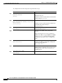
Connecting the 2-Port Asynchronous/Synchronous Serial Modules
This section describes how to connect and verify the status of 2-port asynchronous/synchronous (A/S)
serial modules (WIC-2A/S).
Note
The AGM does not support asynchronous mode operation at this time.
The 2-port A/S serial module has “smart” serial ports. The serial cable attached to one of the module’s
ports can determine the electrical interface type and mode (DTE or DCE).
Six types of serial cables (also called serial adapter cables or serial transition cables) are available from
Cisco Systems for use with the 2-port A/S serial module:
•
EIA/TIA-232 serial cable assembly
•
EIA/TIA-449 serial cable assembly
•
V.35 serial cable assembly
•
X.21 serial cable assembly
•
EIA/TIA-530 serial cable assembly
•
EIA/TIA-530A serial cable assembly
All serial cables have a universal plug at the interface module end. The network end of each cable
provides the physical connectors that are most commonly used for the interface. For example, the
network end of the EIA/TIA-232 serial cable is a DB-25 connector, which is the most widely used
EIA/TIA-232 connector.
All serial interface types, except EIA-530, are available in DTE or DCE mode: DTE with a plug
connector at the network end and DCE with a receptacle at the network end. The V.35 assembly is
available in either mode with either gender at the network end. The EIA/TIA-530 assembly is available
in DTE only.
After you install the 2-port A/S serial module, use the appropriate serial cable to connect the serial port
on the module to one of the following types of equipment (see Figure 2-6):
Cisco Catalyst 4000 Access Gateway Module Installation and Configuration Note
OL-3008-01
2-11
Chapter 2
Installing the Access Gateway Module
Connecting the Voice and WAN Interface Modules
•
Synchronous modem
•
DSU/CSU
•
Other DCE, if connecting to a digital WAN line
To connect the 2-port A/S serial module, perform these steps:
Step 1
Power off the AGM.
Step 2
Connect one end of the appropriate serial cable to a DB-60 port on the module, as shown in Figure 2-6.
Step 3
Connect the other end of the cable to the appropriate type of equipment, as shown in Figure 2-6.
Step 4
Power on the AGM.
Step 5
Verify that the CONN LED goes on, indicating that the serial port on the module detects the WAN serial
connection.
Figure 2-6
Connecting a 2-Port A/S Serial Module (WIC-2A/S)
Synchronous serial
port (DB-60)
CONN LED
CONN
SERIAL
Serial transition
cable
EIA/TIA-232, EIA/TIA-449, V.35,
X.21, or EIA-530 connector
H7370
DSU/CSU or
other DCE
Table 2-3 describes the 2-port A/S serial interface module LED.
Table 2-3
Asynchronous/Synchronous WAN Interface Module LED
LED
Description
CONN
Green indicates that the serial port detects a WAN serial connection.
Connecting the 1-Port and 2-Port Serial Modules
This section describes how to connect and verify the status of the 1- and 2-port serial modules (WIC-1T
and WIC-2T).
Note
The AGM does not support asynchronous mode operation at this time.
Cisco Catalyst 4000 Access Gateway Module Installation and Configuration Note
2-12
OL-3008-01
Chapter 2
Installing the Access Gateway Module
Connecting the Voice and WAN Interface Modules
The 2-port A/S serial module has “smart” serial ports. The serial cable attached to one of the module’s
ports can determine the electrical interface type and mode (DTE or DCE).
Six types of serial cables (also called serial adapter cables or serial transition cables) are available from
Cisco Systems for use with the 2-port A/S serial module:
•
EIA/TIA-232 serial cable assembly
•
EIA/TIA-449 serial cable assembly
•
V.35 serial cable assembly
•
X.21 serial cable assembly
•
EIA/TIA-530 serial cable assembly
•
EIA/TIA-530A serial cable assembly
All serial cables provide a universal plug at the interface module end. The network end of each cable
provides the physical connectors that are most commonly used for the interface. For example, the
network end of the EIA/TIA-232 serial cable is a DB-25 connector, which is the most widely used
EIA/TIA-232 connector.
All serial interface types except EIA-530 are available in the following DTE or DCE mode: DTE with a
plug connector at the network end and DCE with a receptacle at the network end. The V.35 assembly is
available in either mode with either gender at the network end. The EIA/TIA-530 assembly is available
in DTE only.
After you install the 2-port A/S serial module, use the appropriate serial cable to connect the serial port
on the module to one of the following types of equipment (see Figure 2-7):
•
Synchronous modem
•
DSU/CSU
•
Other DCE, if connecting to a digital WAN line
To connect either the 1- or 2-port serial module, perform these steps:
Step 1
Power of the AGM.
Step 2
Connect one end of the appropriate serial cable to a DB-60 port on the module, as shown in Figure 2-7.
Step 3
Connect the other end of the cable to the appropriate type of equipment, as shown in Figure 2-7.
Cisco Catalyst 4000 Access Gateway Module Installation and Configuration Note
OL-3008-01
2-13
Chapter 2
Installing the Access Gateway Module
Connecting the Voice and WAN Interface Modules
Figure 2-7
Connecting a 1- Port Serial Module (WIC-1T)
Synchronous serial
port (DB-60)
CONN LED
CONN
SERIAL
Serial transition
cable
EIA/TIA-232, EIA/TIA-449, V.35,
X.21, or EIA-530 connector
58519
DSU/CSU or
other DCE
Step 4
Power on the AGM.
Step 5
Verify that the CONN LED goes on, indicating that the serial port on the module detects the WAN serial
connection.
Table 2-4 describes the serial WAN interface module LED.
Table 2-4
Serial WAN Interface Module LED
LED
Description
CONN
Green indicates that the serial port detects the WAN serial connection.
Voice Interface Modules
This section describes how to connect the following voice interface modules:
•
Connecting the 2-Port FXS Voice Interface Modules, page 2-14
•
Connecting the 8-Port RJ21 FXS Voice Interface Modules, page 2-16
•
Connecting the 2-Port FXO Voice Interface Modules, page 2-19
•
Connecting the 2-Port E/M Voice Interface Modules, page 2-20
•
Connecting the 2-Port ISDN BRI Modules, page 2-21
Connecting the 2-Port FXS Voice Interface Modules
This section describes how to connect and verify the status of the 2-port FXS voice interface module
(VIC-2FXS or VIC-2FXS-EU).
Cisco Catalyst 4000 Access Gateway Module Installation and Configuration Note
2-14
OL-3008-01
Chapter 2
Installing the Access Gateway Module
Connecting the Voice and WAN Interface Modules
Setting the Jumpers on the 2-Port FXS Module
The 2-port FXS voice interface module has two jumper headers (W3 and W4) that you can use to set
loop-start or ground-start mode. One jumper configures each FXS port. The default setting is loop start.
In the default setting, jumpers are placed over positions 2 and 3 of headers W3 and W4.
Most modern central office (CO) equipment, such as the DMS-100 and 5ESS switches, provides the
calling party control (CPC) and Ring on Seize (ROS) features on loop-start lines. CPC provides faster
disconnection, and ROS minimizes glare (collision of inbound and outbound calls on the same
interface). If your CO does not provide these features on loop-start wires, you may want to configure the
FXS module for ground-start operation instead by moving the jumpers to positions 1 and 2.
For proper operation, you must configure both jumpers identically. In most cases, the jumper setting
should have little or no effect on operation.
Note
Jumper settings apply only to VIC-2FXS.
Connecting the 2-Port FXS Module
Use a standard RJ-11 modular telephone cable to connect the 2-port FXS module to the PSTN or PBX
through a telephone jack.
To connect the 2-port FXS module, perform these steps:
Step 1
Power off the AGM.
Step 2
Connect one end of the cable to one of the RJ-11 ports of the module, as shown on Figure 2-8.
Step 3
Connect the other end of the cable to the RJ-11 wall jack, as shown on Figure 2-8.
Figure 2-8
Connecting a 2-Port FXS Module (VIC-2FXS)
1
IN USE
VIC
FXS
IN USE
RJ-11 ports
SEE MANUAL BEFORE INSTAL
LATION 0
17370
Straight-through
RJ-11-to-RJ-11 cable
RJ-11 wall jack
Step 4
Power on the AGM.
Step 5
verify the LED is green.
Cisco Catalyst 4000 Access Gateway Module Installation and Configuration Note
OL-3008-01
2-15
Chapter 2
Installing the Access Gateway Module
Connecting the Voice and WAN Interface Modules
Table 2-5 describes the FXS voice interface module LED.
Table 2-5
FXS Voice Interface Module LED
LED
Description
IN USE
Green indicates that an off-hook has been detected. Off indicates
that an on-hook has been detected.
The VIC-2FXS-EU voice interface module is intended for use in Europe. In countries where PSTNs do
not use RJ-11 wall jacks, use a suitable adapter to convert the plug on an RJ-11 modular cable to the type
of wall jack connector that is used in your country. These adapters are not sold by Cisco Systems but are
available from other vendors.
Caution
Connect only an FXS interface that is approved for use in your country to the PSTN. Otherwise,
connect the FXS interface only to a PBX.
Connecting the 8-Port RJ21 FXS Voice Interface Modules
This section describes how to connect and verify the status of an 8-port RJ21 FXS module
(WS-U4604-8FXS).
This section describes the following topics:
•
RJ-21 Connectors, page 2-16
•
Connecting the 8-Port RJ21 FXS Module, page 2-17
RJ-21 Connectors
Figure 2-9 shows examples of the RJ-21 telco connector for the RJ-21 port on the 8-port FXS module.
The connectors are available in three cable-to-connector orientations: 90 degrees, 110 degrees, and 180
degrees.
Figure 2-9
RJ-21 Category 5 Telco Interface Cable Connectors
RJ-21 port
90 RJ-21
connector
110 RJ-21
connector
48136
180 RJ-21
connector
Cisco Catalyst 4000 Access Gateway Module Installation and Configuration Note
2-16
OL-3008-01
Chapter 2
Installing the Access Gateway Module
Connecting the Voice and WAN Interface Modules
Because 90 degree RJ-21 connectors have only one screw, they require additional support to hold one
side of the connector to the module. We supply a bracket and a velcro strap in the accessory kit (see
Figure 2-10) for this purpose.
Velcro strap
55735
Figure 2-10 Bracket and Velcro Strap for the RJ-21 Category 5 Telco Interface Cable Connector
To attach the bracket to the 8-port FXS module, perform these steps:
Step 1
Remove the two screws from the 8-port FXS module front panel with a flat-blade screwdriver.
Step 2
Align the screws on the bracket with the holes on the 8-port FXS module, and then tighten them.
Step 3
Align the screw on the 90 degrees RJ-21 connector with the appropriate screw top on the bracket, and
then tighten the screw.
Step 4
Attach the velcro strap as illustrated in Figure 2-11.
Connecting the 8-Port RJ21 FXS Module
Use a standard RJ-21 Category 5 telco connector and cable to connect the 8-port FXS module jack to the
breakout box.
To connect the 8-port RJ21 FXS module, perform these steps:
Step 1
Power off the AGM.
Step 2
Connect one end of the RJ-21 cable to a telco RJ-21, as shown on Figure 2-11.
Step 3
Connect the other end of the cable to the breakout box or patch panel, as shown on Figure 2-11.
Step 4
Power off the AGM.
Step 5
Verify that the HDA LED is green. This LED indicates that IOS is running.
Caution
Do not directly connect Octel voice mail servers to the 8-port FXS module. You must first
connect the servers to a patch panel. Every other output of the Octel voice mail server is a
pair of grounds. (The ring-tip pairs are not defined as port 0, port 1, etc. Instead, they are
Cisco Catalyst 4000 Access Gateway Module Installation and Configuration Note
OL-3008-01
2-17
Chapter 2
Installing the Access Gateway Module
Connecting the Voice and WAN Interface Modules
defined as port 0, ground/ground, port 1, ground/ground, and so on.) Connecting these
grounds directly to the FXS module results in shorting every alternate port on the module
to ground.
Warning
If the symbol of suitability with an overlaid cross appears above a port, you must not connect the
port to a public network that follows the European Union standards. Connecting the port to this
type of public network can cause severe injury or damage your router.
Figure 2-11 Connecting an 8-Port RJ21 FXS Module (WS-U4604-8FXS) to a Breakout Box
180 RJ-21
connector
Velcro strap
90 RJ-21
connector
55809
Breakout box
Table 2-6 describes the 8-port RJ21 FXS module link LED.
Table 2-6
8-Port RJ21 FXS Module Link LED
LED
Description
Link
Green indicates that the telephone or fax
machine is off-hook.
Off indicates that the port is not active
(connected device is on-hook) or that the link is
not connected
Figure 2-12 shows the pinout convention for the telco RJ-21 (tip and ring on 25 pairs). The top row is
ring, the bottom row is tip. For the 8-port FXS module, only the eight pairs to the right are used. The
middle set of eight pairs is shorted together but not to ground.
Cisco Catalyst 4000 Access Gateway Module Installation and Configuration Note
2-18
OL-3008-01
Chapter 2
Installing the Access Gateway Module
Connecting the Voice and WAN Interface Modules
Figure 2-12 Pinout Convention for the Telco RJ-21
Pin 25 Port 24
Port 7
Port 0
Pin 1
Ring
Grounds
Not used
Configurable
50436
Tip
See Table C-3 in Appendix C, “Connector and Cable Specifications” for a mapping of the RJ-21 pinouts
for the 8-port FXS module connector.
Connecting the 2-Port FXO Voice Interface Modules
This section describes how to connect and verify the status of the 2-port FXO voice interface modules
(VIC-2FXO, VIC-2FXO-M1, VIC-2FXO-EU, VIC-2FXO-M2, and VIC-2FXO-M3).
Setting the Jumpers on the 2-Port FXO Module
The 2-port FXO voice interface module includes two jumper headers (W3 and W4) that you can use to
set loop-start or ground-start mode. One jumper configures each FXO port. The default setting is loop
start. In the default setting, jumpers are placed over positions 2 and 3 of headers W3 and W4.
Updated modern CO equipment, such as the DMS-100 and 5ESS switches, provides the CPC and ROS
features on loop-start lines. CPC provides faster disconnection, and ROS minimizes glare (collision of
inbound and outbound calls on the same interface). If your CO does not provide these features on
loop-start lines, you may want to configure the FXO module for ground-start operation instead by
moving the jumpers to positions 1 and 2.
For proper operation, you must configure both jumpers identically. In most cases, the jumper setting
should have little or no effect on operation.
Note
This jumper setting does not apply to VIC-2FXO-EU.
Connecting the 2-Port FXO Module
Use a standard RJ-11 modular telephone cable to connect the 2-port FXO module to the PSTN or PBX
through a telephone jack. To connect the 2-port FXO module, perform these steps:
Step 1
Power off the AGM.
Step 2
Connect one end of the cable to one of the RJ-11 ports of the module, as shown in Figure 2-13.
Step 3
Connect the other end of the cable to the RJ-11 wall jack, as shown in Figure 2-13.
Cisco Catalyst 4000 Access Gateway Module Installation and Configuration Note
OL-3008-01
2-19
Chapter 2
Installing the Access Gateway Module
Connecting the Voice and WAN Interface Modules
Figure 2-13 Connecting a 2-Port FXO Module (VIC-2FXO)
1
IN USE
VIC
FXS
IN USE
RJ-11 ports
SEE MANUAL BEFORE INSTAL
LATION 0
17370
Straight-through
RJ-11-to-RJ-11 cable
RJ-11 wall jack
Step 4
Power on the AGM.
Step 5
verify the IN USE LED is green, indicating that the line is in use.
Table 2-7 describes the E/M voice interface module LED.
Table 2-7
FXO Voice Interface Module LED
LED
Description
IN USE
Green indicates that the line is in use.
The VIC-2FXO-EU voice interface module is intended for use in Europe. In countries where PSTNs do
not use RJ-11 wall jacks, use a suitable adapter to convert the plug on an RJ-11 modular cable to the type
of wall outlet connector that is used in your country. These adapters are not sold by Cisco Systems but
are available from other vendors.
Caution
Connect only an FXO interface that is approved for use in your country to the PSTN. Otherwise,
connect the FXO interface only to a PBX. Connections from the PBX to the PSTN are permitted.
Connecting the 2-Port E/M Voice Interface Modules
This section describes how to connect and verify the status of the 2-port E/M voice interface module
(VIC-2E/M).
Connecting the 2-Port E/M Module
Use a standard RJ-11 modular telephone cable to connect this interface to the PBX. Unlike the FXS and
FXO modules, the E/M module requires an RJ48S connector. The pinout depends on the PBX type and
connection.
To connect the 2-port E/M module, perform these steps:
Cisco Catalyst 4000 Access Gateway Module Installation and Configuration Note
2-20
OL-3008-01
Chapter 2
Installing the Access Gateway Module
Connecting the Voice and WAN Interface Modules
Step 1
Power off the AGM.
Step 2
Connect one end of the RJ-11 cable to one of the RJ48S ports of the module, as shown in Figure 2-14.
Step 3
Connect the other end of the cable to the RJ48S wall jack, as shown in Figure 2-14.
Figure 2-14 Connecting a 2-Port E/M Module (VIC-2E/M)
VIC
E&M
1
IN USE
IN USE
RJ-48S ports
SEE MANUAL BEFORE INSTAL
LATION 0
58546
Straight-through
RJ-11-to-RJ-11 cable
RJ-48S wall jack
Step 4
Power on the AGM.
Step 5
verify the IN USE LED is green, indicating that line is in use.
Table 2-8 describes the E/M voice interface module LED.
Table 2-8
E/M Voice Interface Module LED
LED
Description
IN USE
Green indicates that the line is active.
Connecting the 2-Port ISDN BRI Modules
This section describes how to connect and verify the status of the 2-port ISDN BRI modules
(VIC-2BRI-S/T-TE).
Use the straight through RJ-48C-to-RJ-48C cable that shipped with your AGM.
To connect the 2-port ISDN BRI module, perform these steps:
Step 1
Power off the AGM.
Step 2
Connect one end of the cable to one of the RJ-48C ports of the module, as shown in Figure 2-15.
Step 3
Connect the other end of the cable to one of the RJ-48C S/T ports on an NT1 device, as shown in
Figure 2-15.
Cisco Catalyst 4000 Access Gateway Module Installation and Configuration Note
OL-3008-01
2-21
Chapter 2
Installing the Access Gateway Module
Connecting the Voice and WAN Interface Modules
Caution
To prevent damage to the switch, be sure to connect the cable to the BRI connector only. Do not
connect the cable to any other RJ-48C connector.
Figure 2-15 Connecting a 2-Port ISDN BRI Module (VIC-2B-S/T TE)
RJ-48C ports
B1
B2
OK
VIC
2B-S/T TE
ISDN BRI S/T 1
ISDN BRI S/T 0
SEE
MANUAL
BEFORE
INTALLATION
17367
Straight-through
RJ-45-to-RJ-45 cable
NT1 device
S/T port
Step 4
Power on the AGM.
Step 5
Verify that the OK LED is green, indicating that the module is connected to an ISDN network.
Table 2-9 describes the ISDN BRI voice interface module LEDs.
Table 2-9
ISDN BRI Voice Interface Module LEDs
LED
Description
B1
Green indicates that the call is active on the B1 channel.
B2
Green indicates that the call is active on the B2 channel.
OK
Green indicates that the interface module is connected to an ISDN
network. This LED is on during normal operation.
T1/E1 Multiflex Voice/WAN Interface Modules
This section describes how to connect the following interface modules:
•
Connecting the 1-Port Multiflex Trunk Interface Modules, page 2-23
•
Connecting the 2-Port Multiflex Trunk Interface Modules, page 2-24
Cisco Catalyst 4000 Access Gateway Module Installation and Configuration Note
2-22
OL-3008-01
Chapter 2
Installing the Access Gateway Module
Connecting the Voice and WAN Interface Modules
Connecting the 1-Port Multiflex Trunk Interface Modules
This section describes how to connect and verify the status of the 1-port multiflex trunk interface
modules (VWIC-1MFT-T1, VWIC-1MFT-E1, or VWIC-1MFT-G703).
Use the straight-through RJ-48C-to-RJ-48C cable that shipped with the AGM.
To connect the 1-port multiflex trunk interface module, perform these steps:
Step 1
Power off the AGM.
Step 2
Connect one end of the cable to the RJ-48C port of the module, as shown in Figure 2-16.
Step 3
Connect the other end of the cable to the RJ-48C wall jack at your site, as shown in Figure 2-16.
Figure 2-16 Connecting a 1-Port Multiflex Trunk Interface Module (VWIC-1MFT-T1)
T1 port
(RJ-48C)
VWIC
1MFT-T1
AL
LP
CD
CTRLR T1 0
SEE
MANUAL
BEFORE
INSTALLATION
22158
Straight-through
RJ-48C-to-RJ-48C cable
T1 (RJ-48C)
wall jack
Step 4
Power on the AGM.
Step 5
Verify that the CD LED is green, indicating that the module’s internal DSU/CSU is communicating with
the DSU/CSU at the T1 or E1 service provider’s CO.
Cisco Catalyst 4000 Access Gateway Module Installation and Configuration Note
OL-3008-01
2-23
Chapter 2
Installing the Access Gateway Module
Connecting the Voice and WAN Interface Modules
Table 2-10 describes the 1-port multiflex trunk interface module LEDs.
Table 2-10 1-Port Multiflex Trunk Interface Module LEDs
LED
Description
AL
Yellow indicates that there is a local or remote alarm state.
This LED is off during normal operation.
LP
Yellow indicates that a loopback or line state has been
detected or has been manually set by the user. This LED is
off during normal operation.
CD
Green indicates that a carrier has been detected and that the
internal DSU/CSU in the module is communicating with
another DSU/CSU. This LED is on during normal
operation.
Connecting the 2-Port Multiflex Trunk Interface Modules
This section describes how to connect and verify the status of the 2-port multiflex trunk interface
modules (VWIC-2MFT-T1, VWIC-2MFT-E1, VWIC-2MFT-T1-DI, VWIC-2MFT-E1-DI, or
VWIC-2MFT-G703).
Use the straight-through RJ-48C-to-RJ-48C cable that shipped with the AGM.
To connect the 2-port multiflex trunk interface module, perform these steps:
Step 1
Power off the AGM.
Step 2
Connect one end of the cable to one of the RJ-48C ports of the module, as shown in Figure 2-17.
Step 3
Connect the other end of the cable to the T1 or E1 (RJ-48C) wall jack at your site, as shown in
Figure 2-17.
Figure 2-17 Connecting a 2-Port Multiflex Trunk Interface Module (VWIC-2MFT-E1-DI)
RJ-48C ports
AL
LP
CD
VWIC
2MFT-E1-D1
CTRLR E1 1
CTRLR E1 0
SEE
MANUAL
BEFORE
INSTALLATION
22159
Straight-through
RJ-48C-to-RJ-48C cable
RJ-48C wall jack
Step 4
Power on the AGM.
Cisco Catalyst 4000 Access Gateway Module Installation and Configuration Note
2-24
OL-3008-01
Chapter 2
Installing the Access Gateway Module
Connecting a Terminal to the Console and Ethernet Management Ports
Step 5
Verify that the CD LED is green, indicating that the module’s internal DSU/CSU is communicating with
the DSU/CSU at the T1 or E1 service provider CO.
Table 2-11 describes the 2-port multiflex interface module LEDs.
Table 2-11 2-Port Multiflex Trunk Interface Module LEDs
LED
Description
AL
Yellow indicates that there is a local or remote alarm state.
This LED is off during normal operation.
LP
Yellow indicates that a loopback or line state has been
detected or has been manually set by the user. This LED is
off during normal operation.
CD
Green indicates that a carrier has been detected and that the
internal DSU/CSU in the module is communicating with
another DSU/CSU. This LED is on during normal
operation.
If you have additional modules to install, proceed to the appropriate section in this document.
Connecting a Terminal to the Console and Ethernet Management
Ports
The console and 10/100 Mbps Ethernet management ports are located on the front panel of the AGM.
(See Figure 2-1) The console and Ethernet management ports use an RJ-45 media-dependent interface
crossed-over (MDIX) connector (see Figure 2-18). Table 2-12 lists the console port pinouts and
Table 2-13 lists the 10/100 Mbps Ethernet management port pinouts.
Note
The MDIX ports are crossed over internally. For an MDI-to-MDI or MDIX-to-MDIX connection,
use a crossover cable. For an MDI-to-MDIX connection, use a straight-through cable, which allows
the Tx pins to connect with the Rx pins.
H9463
Figure 2-18 10/100Base-TX RJ-45 Connector Type
Cisco Catalyst 4000 Access Gateway Module Installation and Configuration Note
OL-3008-01
2-25
Chapter 2
Installing the Access Gateway Module
Connecting a Terminal to the Console and Ethernet Management Ports
Table 2-12 Console Port Pinouts
Pin
Signal
Direction
Description
1
RTS
output
Request to send
2
DTR
output
Data terminal ready
3
TXD
output
Transmit data
4
Ground
Ground
5
Ground
Ground
6
RXD
input
Receive data
7
DSR
input
Data set ready
8
CTS
input
Clear to send
Table 2-13 10/100 Ethernet Management Port Pinouts
Pin
Signal
Direction
Description
1
RXD+
input
Receive data diff pair
2
RXD-
input
Receive data diff pair
3
TXD+
output
Transmit data diff pair
4
Unused pair
5
Unused pair
6
TXD-
output
Transmit data diff pair
7
Unused pair
8
Unused pair
Cisco Catalyst 4000 Access Gateway Module Installation and Configuration Note
2-26
OL-3008-01
C H A P T E R
3
Configuring the AGM for the First Time
This chapter describes how to use the setup command facility to configure your Cisco Catalyst 4000
Access Gateway Module (AGM).
Note
The setup command facility prompts you to enter information needed to quickly start the AGM
functioning. The facility steps you through a basic configuration, including configuring LAN and
WAN interfaces.
This chapter contains these major sections:
•
Preparing to Configure the AGM, page 3-1
•
Using the Cisco IOS CLI, page 3-5
•
Interface Configuration Examples, page 3-8
Preparing to Configure the AGM
This section contains information you need to be familiar with before you begin to configure your AGM
for the first time, including interface numbering and steps to take before bringing your AGM online.
This section contains these subsections:
•
Booting the AGM, page 3-1
•
Downloading an Image to Bootflash, page 3-2
•
Configuring the Console Port, page 3-3
•
Configuring the Management Port, page 3-4
•
Understanding the Interface Numbering, page 3-5
Booting the AGM
The factory configures the AGM to automatically load a Cisco IOS image the first time you insert the
module into a Catalyst 4000 family switch. The software configuration register in the AGM determines
where to find the image. The factory sets this register to load the IOS image into bootflash from
configuration register 0x0101. This register enables autoboot at register 0x0103.
Cisco Catalyst 4000 Access Gateway Module Installation and Configuration Note
OL-3008-01
3-1
Chapter 3
Configuring the AGM for the First Time
Preparing to Configure the AGM
Table 3-1 shows the AGM default configuration.
Table 3-1
AGM Default Configuration
Feature
Default Value
Host name
Gateway
Interface configuration
None
VLAN configuration
None
Password encryption
Disabled
Break to console
Ignore
Accessing the AGM
This section describes how to access the AGM from Catalyst Operating System on Supervisor Engine I
and II, and from Cisco IOS on Supervisor Engine III and IV.
Accessing the AGM from Catalyst Operating System
When the AGM finishes power-on self-test diagnostics, and the front panel status LED is green, you can
access the module by entering the session mod/num command at the Switch> prompt. After you enter
this command, the Gateway> prompt appears.
After booting the AGM for the first time, you can configure the interfaces, and then save the
configuration to a file in NVRAM.
Accessing the AGM from Cisco IOS
When the AGM finishes power-on self-test diagnostics, and the front panel status LED is green, you can
access the module by entering the attach module mod/num command at the Switch# prompt. After
you enter this command, the Gateway> prompt appears.
After booting the AGM for the first time, you can configure the interfaces, and then save the
configuration to a file in NVRAM.
Downloading an Image to Bootflash
If you have already configured the AGM, you can download a runtime image from a TFTP server on the
network. To download an image from a TFTP server, no supervisor engine interaction is required. TFTP
downloads can take place over the out-of-band Ethernet management port, or over the internal Gigabit
Ethernet connections. To perform a network download over the internal Gigabit Ethernet connections,
you must first bring up these ports and configure them.
Note
Before you can download an image, you must first configure the management port. See
the“Configuring the Management Port” section on page 3-4.
Cisco Catalyst 4000 Access Gateway Module Installation and Configuration Note
3-2
OL-3008-01
Chapter 3
Configuring the AGM for the First Time
Preparing to Configure the AGM
To download an image to bootflash from Catalyst Operating System on Supervisor Engine I and II,
access the AGM using the session command:
Console> (enable) session
To download an image to bootflash from Cisco IOS on supervisor engine III and IV, access the AGM
using the attach command:
Switch# attach module module_number
Enter the following command in privileged mode:
copy tftp:
[/directory] /filename [/directory] /filename
Configuring the Console Port
The console port mode switch allows you to connect a terminal to the AGM using either a Catalyst 5000
family supervisor engine III console cable or the console cable and adapters provided with a
Catalyst 4000 family switch.
Note
Use a paper clip or a small, pointed object to access the console port mode switch.
Use the console port mode switch as follows:
•
Mode 1—Switch is in the (factory default) in position to connect a terminal to the console port using
the console cable and data terminal equipment (DTE) adapter labeled Terminal that shipped with
the switch.
You can also use this mode to connect a modem to the console port using the console cable and data
communications equipment (DCE) adapter (labeled “Modem”) that shipped with the switch.
•
Note
Mode 2—Switch is in the out position to connect a terminal to the console port using the Catalyst
5000 Family supervisor engine III console cable (not provided).
You should not have to connect a terminal to the AGM console port.
When your terminal is connected to the supervisor engine I or II console port, use the session command
to access the Layer 3 services module for Gateway configuration.
When your terminal is connected to the supervisor engineIII or IV console port, use the attach module
command to access the Layer 3 services module for Gateway configuration.
The console port allows you to access the AGM either locally (with a console terminal) or remotely (with
a modem). The console port is an EIA/TIA-232 asynchronous, serial connection with an RJ-45
connector.
For complete console port cabling specifications and pinouts, refer to the Catalyst 4000 Family
Installation Guide.
Note
The accessory kit that shipped with your Catalyst 4000 family switch contains the cable and adapters
to connect a terminal or modem to the console port. These cables and adapters are the same as those
shipped with the Cisco 2500 series routers and other Cisco products.
Cisco Catalyst 4000 Access Gateway Module Installation and Configuration Note
OL-3008-01
3-3
Chapter 3
Configuring the AGM for the First Time
Preparing to Configure the AGM
Connecting a Terminal
To connect a terminal to the console port using the cable and adapters provided with the Catalyst 4000
family switch, ensure that the console port mode switch is in the in position (factory default). Connect
to the port using the RJ-45-to-RJ-45 cable and RJ-45-to-DB-25 DTE adapter or RJ-45-to-DB-9 DTE
adapter (labeled “Terminal”).
To connect a terminal using a Catalyst 5000 Family supervisor engine III console cable, place the
console port mode switch in the out position. Connect to the port using the Catalyst 4000 family
supervisor engine III cable and the appropriate adapter for the terminal connection.
Check the documentation that came with your terminal to determine the baud rate. The baud rate of the
terminal must match the default baud rate (9600 baud) of the console port.
Set up the terminal as follows:
•
9600 baud
•
8 data bits
•
No parity
•
1 stop bit
•
No flow control
Connecting a Modem
To connect a modem to the console port, ensure that the console port mode switch is in the in position
(factory default position). Connect the modem to the port using the RJ-45-to-RJ-45 cable and the
RJ-45-to-DB-25 DCE adapter (labeled “Modem”).
Configuring the Management Port
You can manage the AGM through the 10/100 management port by assigning it an IP address.
Caution
By default, the Fast Ethernet interface does not route data traffic. We do not recommend that you
override this default configuration.
The supervisor engine reports one IP address assigned to the AGM that can be used for network
management through the Cisco Stack MIB.
If the Ethernet 10/100 management port is up and an IP address has been configured, the AGM selects
the IP address assigned to the 10/100 Ethernet management port. If the management port is down or an
IP address has not been configured, the AGM randomly selects an IP address that has been assigned to
one of the Gigabit Ethernet ports or port channels as the network management IP address, provided the
interface or subinterface associated with this IP address is up at the time of selection.
If the selected network management IP address is removed or the interface or subinterface associated
with this IP address is shut down, the AGM selects another IP address as a replacement.
If all the interfaces are down or no IP address has been assigned to any interface or subinterface that is
up, the IP address for network management is 0.0.0.0.
After each IP address selection or change of the IP address, the AGM sends an unsolicited message to
the supervisor engine, which then populates the IP address attribute of the Cisco Stack MIB entry of the
AGM.
Cisco Catalyst 4000 Access Gateway Module Installation and Configuration Note
3-4
OL-3008-01
Chapter 3
Configuring the AGM for the First Time
Using the Cisco IOS CLI
Understanding the Interface Numbering
The AGM has three slots in which you can install interface cards:
•
Slot 1 supports voice interface cards (VICs), WAN interface cards (WICs), and voice and WAN
interface cards (VWICs).
•
Slot 2 supports voice interface cards (VICs), WAN interface cards (WICs), and voice and WAN
interface cards (VWICs).
•
Slot 3 supports only VICs and VWICs (no WICs).
•
Slot 4 is reserved for the 8-port RJ21 FXS module.
Each individual interface is identified by a slot number and a port number. The slots are numbered as
follows:
•
Slot 0 supports the following main board embedded interfaces:
– Console port (con 0)
– Ethernet Management port (Fast Ethernet 0/0)
– Gigabit Ethernet backplane connection (Gigabit Ethernet 0/0:S)
•
Slot 1 ports are numbered from right to left (1/1 and 1/0)
On the WIC-2A/S, the top slot is 0 and the bottom slot is 1.
Note
•
Slot 2 ports are numbered from right to left (2/1 and 2/0)
•
Slot 3 ports are numbered from right to left (3/0 and 3/1)
•
Slot 4 ports (on the 8-Port FXS module) are sequentially numbered from right to left, starting with
0 for the right-most port. As the 8-port FXS module is located in slot 4, the eight ports are numbered
4/0 to 4/7.
When you configure an interface, identify the interface name before the slot and port numbers. For
example, if you install a serial T1 VWIC interface in slot 2, port 0 would be labeled as serial 2/0.
The Gigabit Ethernet port interface name, slot, and port number are gigabit-ethernet 0/0:S. The S
represents the possible subinterfaces, which could be one of six VLAN connections.
Figure 3-1 shows the AGM front panel.
Figure 3-1
AGM Front Panel
WS-X4604-GWY
WAN GATEWAY
STATUS
VIC
2FXS
VWIC
2MFT-T1-D1
0
1
SEE MANUAL BEFORE INSTALLATION
CONN
CONSOLE
VWIC 1
10/100MGT
0
1
DSP BANK
READY
2
ACTIVE
CTRLR T1 1
CTRLR T1 0
SEE
MANUAL
BEFORE
INSTALLATION
FLEXSLOT 4
VWIC 2
38654
WIC
2A/S
CONN
VIC 3
3
FLEXSLOT 4 STATUS
Using the Cisco IOS CLI
Cisco voice gateways run versions of the Cisco IOS software that includes specialized adaptations for
Voice over IP (VoIP) and Media Gateway Control Protocol (MGCP). If you are familiar with other
versions of Cisco IOS, you will find configuring Cisco voice gateways straightforward because you will
use the Cisco IOS CLI, with which you are familiar.
Cisco Catalyst 4000 Access Gateway Module Installation and Configuration Note
OL-3008-01
3-5
Chapter 3
Configuring the AGM for the First Time
Using the Cisco IOS CLI
If you have never used the Cisco IOS CLI, you should still be able to perform the configuration required
using the instructions and examples provided in this guide. To help get you started, this section provides
a brief overview of some of the main features of the CLI. For more information, refer to the Cisco IOS
configuration guides and command references.
This section contains these topics:
•
Getting Help, page 3-6
•
Command Modes, page 3-6
•
Disabling a Command or Feature, page 3-7
•
Saving Configuration Changes, page 3-8
Getting Help
Use the question mark (?) and arrow keys to help you enter commands, as follows:
•
For a list of available commands, enter a question mark, for example:
Gateway> ?
•
To complete a command, enter a few known characters followed by a question mark (with no space),
for example:
Gateway> s?
•
For a list of command variables, enter the command followed by a space and a question mark, for
example:
Gateway> show ?
•
To redisplay a command you previously entered, press the Up Arrow key. You can continue to press
the Up Arrow key for more commands.
Command Modes
The Cisco IOS interface is divided into different modes. Each command mode permits you to configure
different components on your gateway. The commands available at any given time depend on which
mode you are currently using. Entering a question mark (?) at the prompt displays a list of commands
available for each command mode. Table 3-2 lists the most common command modes.
Table 3-2
Common Command Modes
Command Mode
Access Method
Gateway Prompt Displayed
Exit Method
User EXEC
Log in.
hostname>
Use the logout command.
The default is Gateway>
Privileged EXEC
hostname#
From user EXEC mode,
enter the enable command. The default is Gateway#
To exit to user EXEC mode, use the
disable, exit, or logout command.
Global configuration
From the privileged EXEC
mode, enter the configure
terminal command.
To exit to privileged EXEC mode, use
the exit or end command, or press
Ctrl-Z.
hostname (config)#
The default is
Gateway(config)#
Cisco Catalyst 4000 Access Gateway Module Installation and Configuration Note
3-6
OL-3008-01
Chapter 3
Configuring the AGM for the First Time
Using the Cisco IOS CLI
Table 3-2
Common Command Modes
Command Mode
Access Method
Gateway Prompt Displayed
Exit Method
Interface
configuration
From the global
configuration mode, enter
the interface type number
command, such as
FastEthernet int 0/0.
hostname (config-if)#
To exit to global configuration mode,
use the exit command.
From the global
configuration mode, enter
the dial-peer voice
command, such as
dial-peer voice 1
pots/voip.
hostname(config-
Dial-peer
configuration
Timesaver
The default is
Gateway(config-if)#
dial-peer)
The default is
Gateway(config-dial-peer)#
To exit directly to privileged EXEC
mode, press Ctrl-Z.
To exit to global configuration mode,
use the exit command.
To exit directly to privileged EXEC
mode, press Ctrl-Z.
Each command mode restricts you to a subset of commands. If you are having trouble
entering a command, check the prompt and enter the question mark (?) for a list of available
commands. You might be in the wrong command mode or using the wrong syntax.
In the following example, which uses the default prompt (Gateway>), notice how the prompt changes
after each command to indicate a new command mode:
Gateway> enable
Password: <enable password>
Gateway#configure terminal
Gateway(config-if)# line 0
Gateway(config-line)# controller t1 1/0
Gateway(config-controller)# exit
Gateway(config)# exit
Gateway#
%SYS-5-CONFIG_I: Configured from console by console
The last message is normal and does not indicate an error. Press Return to return to the prompt.
Note
You can press Ctrl-Z in any mode to return immediately to privileged EXEC mode
(Gateway#), instead of entering exit, which returns you to the previous mode.
Disabling a Command or Feature
If you want to undo a command you entered or disable a feature, enter the keyword no before most
commands; for example, no mgcp.
Cisco Catalyst 4000 Access Gateway Module Installation and Configuration Note
OL-3008-01
3-7
Chapter 3
Configuring the AGM for the First Time
Interface Configuration Examples
Saving Configuration Changes
You need to enter the copy running-config startup-config command to save your configuration
changes to nonvolatile random-access memory (NVRAM), so the changes are not lost if there is a system
reload or power outage. For example:
Gateway# copy running-config startup-config
Building configuration...
Note
It might take a minute or two to save the configuration to NVRAM. After the configuration
has been saved, the privileged EXEC mode prompt (Gateway#) reappears.
Interface Configuration Examples
To configure the AGM interfaces, you can use the setup command facility and automate the process. If
you need interface configuration examples for using the setup command facility, go to the following url:
http://www.cisco.com/en/US/partner/products/hw/routers/ps259/products_configuration_guide_chapte
r09186a008007e60a.html#32818
Cisco Catalyst 4000 Access Gateway Module Installation and Configuration Note
3-8
OL-3008-01
C H A P T E R
4
Configuring the Data Interfaces
This chapter describes how to configure the data interfaces on the Cisco Catalyst 4000
Access Gateway Module (AGM).
This chapter contains the following major sections:
•
About Configuring Data Interfaces, page 4-1
•
Configuring the Host Name and Password, page 4-1
•
Configuring the Fast Ethernet Interface, page 4-3
•
Configuring Asynchronous/Synchronous Serial Interfaces, page 4-4
•
Configuring ISDN BRI Interfaces, page 4-7
•
Configuring T1 and E1 Interfaces, page 4-8
•
Verifying the Interface Configuration, page 4-12
•
Saving Configuration Changes, page 4-13
About Configuring Data Interfaces
To configure a data interface, you must be in configuration mode. In this mode, you enter Cisco IOS
command-line interface (CLI) commands at the Gateway prompt. This chapter describes some of the
most commonly used configuration procedures.
For advanced configuration topics, refer to the Cisco IOS configuration guide and command reference
publications. These publications are available on the Documentation CD-ROM or on Cisco.com. You
can also order printed copies separately.
Configuring the Host Name and Password
One of the first configuration tasks you might want to do is configure the host name and set an encrypted
password. Configuring a host name allows you to distinguish multiple AGMs. Setting an encrypted
password allows you to prevent unauthorized configuration changes.
Cisco Catalyst 4000 Access Gateway Module Installation and Configuration Note
OL-3008-01
4-1
Chapter 4
Configuring the Data Interfaces
Configuring the Host Name and Password
To configure the host name and password, perform these steps:
Step 1
Command
Purpose
gateway> enable
Enter enable mode.
Password: password
Enter the password.
gateway#
Step 2
gateway# configure terminal
Enter configuration commands, one per line.
End with Ctrl-Z.
gateway(config)#
You know you have entered enable mode when the
prompt changes to gateway#.
Enter global configuration mode.
You know you have entered global configuration
mode when the prompt changes to
gateway(config)#.
Step 3
gateway(config)# hostname gwy1
gwy1(config)#
Step 4
gwy1(config)# enable secret guessme
Provide the AGM a meaningful name. Substitute
your host name for gwy1.
Substitute your enable secret password for
guessme.
This password gives you access to privileged
EXEC mode. When you type enable at the EXEC
prompt (gateway>), you must enter the enable
secret password to gain access to configuration
mode.
Step 5
gwy1(config)# line con 0
gwy1(config-line)#
Enter line configuration mode to configure the
console port. When you enter line configuration
mode, the prompt changes to
gwy1(config-line)#.
Step 6
gwy1(config-line)# exec-timeout 0 0
Enter exec-timeout 0 0 to prevent the AGM’s
EXEC facility from timing out if you do not type
any information on the console screen for an
extended period.
Step 7
gwy1(config-line)# exit
Exit back to global configuration mode.
gwy1(config)#
Cisco Catalyst 4000 Access Gateway Module Installation and Configuration Note
4-2
OL-3008-01
Chapter 4
Configuring the Data Interfaces
Configuring the Fast Ethernet Interface
To verify that you configured the correct host name and password, perform these steps:
Step 1
Enter the show config command:
gwy1# show config
Using 1888 out of 126968 bytes
!
version XX.X
.
.
.
!
hostname gwy1
!
enable secret 5 $1$60L4$X2JYOwoDc0.kqa1loO/w8/
.
.
.
Check the host name and encrypted password displayed near the top of the command output.
Step 2
Exit global configuration mode and attempt to reenter it using the new enable password:
gwy1# exit
.
.
.
gwy1 con0 is now available
Press RETURN to get started.
gwy1> enable
Password: guessme
gwy1#
Tip
If you are having trouble, verify that the Caps Lock function is off; passwords are case
sensitive.
Configuring the Fast Ethernet Interface
This section describes how to configure the Fast Ethernet interface on the AGM.
Timesaver
Before you begin, disconnect all WAN cables from the AGM to keep it from trying to run the
AutoInstall process. The AGM tries to run AutoInstall whenever you bring the module online if there
is a WAN connection on both ends and the AGM does not have a valid configuration file stored in
NVRAM (for instance, when you add a new interface). The AGM can take several minutes to
determine that AutoInstall is not connected to a remote TCP/IP host.
Cisco Catalyst 4000 Access Gateway Module Installation and Configuration Note
OL-3008-01
4-3
Chapter 4
Configuring the Data Interfaces
Configuring Asynchronous/Synchronous Serial Interfaces
To configure the Fast Ethernet interface, perform these steps:
Step 1
Command
Purpose
gateway> enable
Enter enable mode.
Password: <password>
Enter the password.
gateway#
Step 2
gateway# configure terminal
Enter configuration commands, one per
line. End with Ctrl-Z.
gateway(config)#
You know you have entered enable mode when the prompt
changes to gateway#.
Enter global configuration mode.
You know you have entered global configuration mode
when the prompt changes to gateway(config)#.
Step 3
gateway(config)# ip routing
Enable routing protocols as required for your global
configuration.
Step 4
gateway(config)# interface
fastethernet 0/0
Enter interface configuration mode.
gateway(config-if)#
You know you have entered interface configuration mode
when the prompt changes to gateway(config-if)#.
Step 5
gateway(config-if)# ip address
172.16.74.3 255.255.255.0
Assign an IP address and subnet mask to the interface.
Step 6
gateway(config-if)# exit
Exit back to global configuration mode.
If your AGM has more than one Fast Ethernet interface
that you need to configure, repeat Steps 4 through 6.
Step 7
gateway(config)# Ctrl-Z
gateway#
When you finish configuring interfaces, return to enable
mode.
You know you have entered enable mode when the prompt
changes to gateway#.
Configuring Asynchronous/Synchronous Serial Interfaces
This section describes how to configure the serial interfaces on your asynchronous/synchronous serial
WIC.
Note
Timesaver
The asynchronous/synchronous serial WIC supports synchronous mode only.
Before you begin, disconnect all WAN cables from the AGM to keep it from trying to run the
AutoInstall process. The AGM tries to run AutoInstall whenever you bring the module online if there
is a WAN connection on both ends and the AGM does not have a valid configuration file stored in
NVRAM (for instance, when you add a new interface). The AGM can take several minutes to
determine that AutoInstall is not connected to a remote TCP/IP host.
Cisco Catalyst 4000 Access Gateway Module Installation and Configuration Note
4-4
OL-3008-01
Chapter 4
Configuring the Data Interfaces
Configuring Asynchronous/Synchronous Serial Interfaces
To configure the serial interfaces, perform these steps:
Step 1
Command
Purpose
gateway> enable
Enter enable mode.
Password: <password>
Enter the password.
gateway#
Step 2
You know you have entered enable mode when the prompt
changes to gateway#.
gateway# configure terminal
Enter configuration commands, one
per line. End with Ctrl-Z.
gateway(config)#
Enter global configuration mode.
You know you have entered global configuration mode
when the prompt changes to gateway(config)#.
Step 3
gateway(config)# ip routing
Enable routing protocols as required for your global
configuration.
Step 4
gateway(config)# interface serial
1/0
Enter the interface configuration mode.
You know you have entered interface configuration mode
when the prompt changes to gateway(config-if)#.
gateway(config-if)#
Step 5
gateway(config-if)# ip address
172.16.74.1 255.255.255.0
Assign the IP address and subnet mask to the interface.
Note
All serial ports are initially configured as
synchronous.
Step 6
gateway(config-if)# clock rate 7200
To use a port in Data Communication Equipment (DCE)
mode, connect a DCE cable and set the internal transmit
clock signal (TXC) speed in bits per second. (For ports used
in Data Terminal Equipment (DTE) mode, the AGM
automatically uses the external timing signal.)
Step 7
gateway(config-if)#
dce-terminal-timing-enable
When a port is operating in DCE mode, the default
operation is for the DCE to send serial clock transmit (SCT)
and serial clock receive (SCR) clock signals to the DTE, and
for the DTE to return an serial clock transmit external
(SCTE) signal to the DCE.
If the DTE does not return an SCTE signal, enter this
command to configure the DCE port to use its own clock
signal.
Step 8
gateway(config-if)# invert-txcclock
An AGM that uses long cables might experience high error
rates when operating at higher transmission speeds, because
the clock and data signals can shift out of phase.
If a DCE port is reporting a high number of error packets,
you can often correct the shift by inverting the clock using
this command.
Step 9
gateway(config-if)# nrzi-encoding
All serial interfaces support both nonreturn to zero (NRZ)
and nonreturn to zero inverted (NRZI) formats. NRZ is the
default; NRZI is commonly used with EIA/TIA-232
connections in IBM environments. To enable NRZI
encoding on an interface, enter this command.
Cisco Catalyst 4000 Access Gateway Module Installation and Configuration Note
OL-3008-01
4-5
Chapter 4
Configuring the Data Interfaces
Configuring Asynchronous/Synchronous Serial Interfaces
Step 10
Command
Purpose (continued)
gateway(config-if)# exit
Exit back to global configuration mode.
If your AGM has more that one serial interface that you
need to configure, repeat Steps 4 through 14.
Step 11
When you finish configuring the interface, return to enable
mode.
gateway(config)# Ctrl-z
gateway#
Table 4-1 lists the half-duplex timer commands.
Table 4-1
Half-duplex Timer Commands
Timer
Syntax
Default Setting
(Milliseconds)
CTS delay1
half-duplex timer cts-delay
100
CTS drop timeout
half-duplex timer cts-drop-timeout
5000
DCD2
half-duplex timer dcd-drop-delay
100
half-duplex timer dcd-txstart-delay
100
RTS drop delay
half-duplex timer rts-drop-delay
100
RTS timeout
half-duplex timer rts-timeout
2000
Transmit delay
half-duplex timer transmit-delay
0
drop delay
DCD transmission start delay
3
1. CTS = Clear To Send.
2. DCD = Data Carrier Detect
3. RTS = Request To Send.
The following clock rate settings are for 2-port asynchronous/synchronous serial WICs:
•
1200 bps
•
2400 bps
•
4800 bps
•
9600 bps
•
14400 bps
•
19200 bps
•
28800 bps
•
32000 bps
•
38400 bps
•
56000 bps
•
57600 bps
•
64000 bps
•
72000 bps
•
115200 bps
•
125000 bps
•
128000 bps
Cisco Catalyst 4000 Access Gateway Module Installation and Configuration Note
4-6
OL-3008-01
Chapter 4
Configuring the Data Interfaces
Configuring ISDN BRI Interfaces
Configuring ISDN BRI Interfaces
This section describes how to configure the interfaces on the basic rate interface (BRI) card of your
AGM.
Note
Timesaver
Before using a AGM with an ISDN BRI interface, you must order a correctly configured ISDN BRI
line from your local telecommunications service provider. ISDN BRI provisioning refers to the types
of services provided by the ISDN BRI line. Although provisioning is performed by your ISDN BRI
service provider, you must tell the provider what you want.
Before you begin, disconnect all WAN cables from the AGM to keep it from trying to run the
AutoInstall process. The AGM tries to run AutoInstall whenever you bring it online, if there is a
WAN connection on both ends and the AGM does not have a valid configuration file stored in
NVRAM (for instance, when you add a new interface). The AGM can take several minutes to
determine that AutoInstall is not connected to a remote TCP/IP host.
To configure ISDN BRI interfaces, perform these steps:
Step 1
Command
Purpose
gateway> enable
Enter enable mode.
Password:
Step 2
< password>
Enter the password.
gateway#
You know you have entered enable mode when the prompt
changes to gateway#.
gateway# configure terminal
Enter global configuration mode.
Enter configuration commands, one per
line. End with Ctrl-Z.
Step 3
gateway(config)#
You know you have entered global configuration mode
when the prompt changes to gateway(config)#.
gateway(config)# isdn switch-type
switch-type
Enter an ISDN switch type. See Table 4-2 for a list of ISDN
switch types.
Note
Switch types configured in interface
configuration mode override this setting for the
configured interface.
Step 4
gateway(config)# ip routing
Enable routing protocols as required for your global
configuration.
Step 5
gateway(config)# interface bri 2/0
Enter the interface configuration mode.
gateway(config-if)#
You know you have entered interface configuration mode
when the prompt changes to gateway(config-if)#.
gateway(config-if)# ip address
172.16.74.2 255.255.255.0
Assign the IP address and subnet mask to the interface.
Step 6
gateway(config-if)# isdn
switch-type basic-5ess
If you are configuring this interface for voice, enter the
switch type instead of an IP address.
Cisco Catalyst 4000 Access Gateway Module Installation and Configuration Note
OL-3008-01
4-7
Chapter 4
Configuring the Data Interfaces
Configuring T1 and E1 Interfaces
Step 7
Command
Purpose (continued)
gateway(config-if)# exit
Exit back to global configuration mode.
If your AGM has more than one BRI interface that you need
to configure, repeat Steps 5 through 7.
Step 8
gateway(config)# memory-size iomem
40
By default, the AGM allocates 25 percent of DRAM to
shared memory (used for data transmitted (or received) by
WAN interface cards). Specifying memory-size iomem 40,
increases shared memory from 25 percent to 40 percent.
Step 9
gateway(config)# Ctrl-z
When you finish configuring the interface, return to enable
mode.
gateway#
Table 4-2 lists the supported ISDN switch types by country.
Table 4-2
ISDN Switch Types
Region
ISDN Switch
Type
Description
Australia
basic-ts013
Australian TS013 switches
Europe
basic-1tr6
German 1TR6 ISDN switches
basic-nwnet3
Norwegian NET3 ISDN switches (phase 1)
basic-net3
NET3 ISDN switches (UK and others)
vn2
French VN2 ISDN switches
vn3
French VN3 ISDN switches
Japan
ntt
Japanese NTT ISDN switches
New Zealand
basic-nznet3
New Zealand NET3 switches
North
America
basic-5ess
AT&T basic rate switches
basic-dms100
NT DMS-100 basic rate switches
basic-nil1
National ISDN-1 switches
Configuring T1 and E1 Interfaces
This section describes how to configure a T1/E1 multiflex trunk interface on your AGM. It describes a
basic configuration, including how to enable the interface and to specify IP routing. Depending on your
own requirements and the protocols you plan to route, you might also need to enter other configuration
commands.
Timesaver
Before you begin, disconnect all WAN cables from the AGM to keep it from trying to run the
AutoInstall process. The AGM tries to run AutoInstall whenever you bring it online if there is a WAN
connection on both ends and the AGM does not have a valid configuration file stored in NVRAM
(for instance, when you add a new interface). The AGM can take several minutes to determine that
AutoInstall is not connected to a remote TCP/IP host.
Cisco Catalyst 4000 Access Gateway Module Installation and Configuration Note
4-8
OL-3008-01
Chapter 4
Configuring the Data Interfaces
Configuring T1 and E1 Interfaces
Configuring T1 Interfaces
To configure a new T1, Channelized T1 (CT1)/PRI, or CT1/PRI-channel status unit (CSU) interface, or
to change the configuration of an existing interface, perform these steps:
Step 1
Command
Purpose
gateway> enable
Enter enable mode.
Password:
Step 2
<password>
Enter the password.
gateway#
You know you have entered enable mode when the prompt
changes to gateway#.
gateway# configure terminal
Enter global configuration mode.
Enter configuration commands, one
per line. End with Ctrl-Z.
gateway(config)#
You know you have entered global configuration mode
when the prompt changes to gateway(config)#.
Step 3
gateway(config)# ip routing
Enable routing protocols as required for your global
configuration.
Step 4
gateway(config)# controller t1 1/0
Enter controller configuration mode for the CT1/PRI
interface at the specified slot/port location.
This example configures a T1 interface in slot 1 and unit 0.
Step 5
gateway(config-controller)# clock
source line
Specify which end of the circuit provides clocking.
The clock source should be set to use internal clocking
only for testing the network or if the full T1 line is used as
the channel group. Only one end of the T1 line should be
set to internal.
Step 6
gateway(config-controller)#
framing esf
Specify the T1 framing type. The framing type defines the
control bits and data bits. Cisco supports super frame (SF)
and extended super frame (ESF) for T1s.
SF is used in channel bank robbed bit signalling (RBS)
configurations. SF uses the framing bit to identify the
channel and voice-related signaling within the frame. SF
is not recommended for PRI configurations.
ESF is required for 64 kb operation on DS0s. ESF requires
2k-framing bits for synchronization. The remaining 6k is
used for error detection, CRC, and data link monitoring.
ESF is recommended for PRI configurations.
This example uses ESF.
Cisco Catalyst 4000 Access Gateway Module Installation and Configuration Note
OL-3008-01
4-9
Chapter 4
Configuring the Data Interfaces
Configuring T1 and E1 Interfaces
Step 7
Command
Purpose (continued)
gateway(config-controller)#
linecode b8zs
Specify the line code format. This is an encoding method
used to allow synchronous data to be transmitted in a
compatible format for T1 transmission. Common line
codes are RZ (return to zero), NRZ (non-return to zero),
binary zero 0 substitution (B8ZS), alternate mark
inversion (AMI), and HDB3 (high density bipolar
order 3).
B8ZS is the most popular line-code scheme used in North
America. To maintain clock synchronization, B8ZS
replaces a string of 8 binary 0s with variations. B8ZS is
more reliable than AMI, and it should be used with PRI
configurations.
Step 8
gateway(config-controller)#
channel-group 0 timeslots 1,3-5,7
Specify the channel group and time slots to be mapped.
When configuring a T1 data line, channel-group numbers
can be values from 0 to 23.
Timeslots are assigned to channels. One or more timeslots
or ranges of timeslots belong to the channel group. The
first timeslot is numbered 1. For a T1 controller, the
timeslot range is from 1 to 24. For T1 PRI scenarios, all 24
T1 timeslots are assigned as ISDNPRI channels.
The default line speed when configuring a T1 controller is
56 kbps.
In this example, channel-group 0 consists of 5 timeslots
and runs at a speed of 56 kbps per timeslot.
Step 9
gateway(config-controller)#
interface serial 1/0:0
gateway(config-if)#
Configure each channel group as a virtual serial interface.
Specify the T1 interface (1), unit number (0), and channel
group (0) to modify and enter the interface configuration
mode.
You know you have entered interface configuration mode
when the prompt changes to gateway(config-if)#.
Step 10 gateway(config-if)# ip address
Assign an IP address and subnet mask to the interface.
10.1.15.1 255.255.255.0
Step 11 gateway(config-if)# exit
Exit back to global configuration mode.
If your AGM has more than one CT1/PRI interface that
you need to configure, repeat Steps 4 through 10.
Step 12 gateway(config)# Ctrl-z
gateway#
When you finish configuring interfaces, return to enable
mode.
Cisco Catalyst 4000 Access Gateway Module Installation and Configuration Note
4-10
OL-3008-01
Chapter 4
Configuring the Data Interfaces
Configuring T1 and E1 Interfaces
Configuring E1 Interfaces
To configure a new E1 interface (balanced or unbalanced) or to change the configuration of an existing
interface, perform these steps:
Step 1
Command
Purpose
gateway> enable
Enter enable mode.
Password:
Step 2
< password>
Enter the password.
gateway#
You know you have entered enable mode when the
prompt changes to gateway#.
gateway# configure terminal
Enter global configuration mode.
Enter configuration commands, one per
line. End with Ctrl-Z.
You know you have entered global configuration mode
when the prompt changes to gateway(config)#.
gateway(config)#
Step 3
gateway(config)# ip routing
Enable routing protocols as required for your global
configuration.
Step 4
gateway(config)# controller e1 1/0
Enter controller configuration mode for the CE1/PRI
interface at the specified slot/port location.
This example configures a E1 interface in slot 1 and
unit 0.
Step 5
gateway(config-controller)# framing
crc4
Specify the framing type as cyclic redundancy check 4
(CRC4).
Step 6
gateway(config-controller)# linecode
hdb3
Specify the line code format as high-density bipolar 3
(HDB3).
Step 7
gateway(config-controller)#
channel-group 0 timeslots 1,3-5,7
Specify the channel group and time slots to be mapped.
When configuring a E1 data line, channel-group
numbers can be values from 0 to 30.
Timeslots are assigned to channels. One or more
timeslots or ranges of timeslots belong to the channel
group. The first timeslot is numbered 1. For an E1
controller, the timeslot range is from 1 to 31. For E1
PRI scenarios, all 31 T1 timeslots are assigned as
ISDNPRI channels.
The default line speed when configuring an E1
controller is 64 kbps.
In this example, channel-group 0 consists of 5 timeslots
and runs at a speed of 64 kbps per timeslot.
Step 8
gateway(config-controller)# interface
serial 1/0:0
gateway(config-if)#
Configure each channel group as a virtual serial
interface. Specify the E1 interface, unit number, and
channel group to modify and enter the interface
configuration mode.
You know you have entered interface configuration
mode when the prompt changes to
gateway(config-if)#.
Cisco Catalyst 4000 Access Gateway Module Installation and Configuration Note
OL-3008-01
4-11
Chapter 4
Configuring the Data Interfaces
Verifying the Interface Configuration
Command
Purpose (continued)
Step 9
gateway(config-if)# ip address
10.1.15.1 255.255.255.0
Assign an IP address and subnet mask to the interface.
Step 10
gateway(config-if)# exit
Exit back to global configuration mode.
If your AGM has more than one CE1/PRI interface that
you need to configure, return to Step 4.
Step 11
gateway(config)# Ctrl-z
gateway#
When you finish configuring interfaces, return to
enable mode.
Verifying the Interface Configuration
After configuring the new interface, you can perform the following tests to verify that the new interface
is operating correctly:
•
Display the AGM hardware configuration with the show version command. Check that the list
includes the new interface.
•
Specify an interface with the show interfaces [type slot/port] command and verify that the first line
of the display shows the interface with the correct slot and port number, and that the interface and
line protocol are in the correct state, up or down.
•
Display the protocols configured for the entire AGM and for individual interfaces with the show
protocols command. If necessary, return to configuration mode to add or remove protocol routing
on the AGM or its interfaces.
•
Display the running configuration with the show running-config command, and the configuration
stored in NVRAM using the show startup-config command.
•
Use the ping command to send an echo request to a specified IP address. Each returned signal is
displayed as an exclamation point (!) on the console; each signal that is not returned before the
timeout is displayed as a period (.). A series of exclamation points (!!!!!) indicates a good
connection; a series of periods (.....) or the message “timed out” or “failed” indicate that the
connection failed.
If an interface is down and you configured it as up, or if the displays indicate that the hardware is not
functioning properly, make sure that the new interface is properly connected and configured.
Cisco Catalyst 4000 Access Gateway Module Installation and Configuration Note
4-12
OL-3008-01
Chapter 4
Configuring the Data Interfaces
Saving Configuration Changes
Saving Configuration Changes
To prevent the loss of the AGM configuration, you need to save it to NVRAM.
To save configuration changes, perform these steps:
Command
Step 1
Password:
Step 2
Step 3
Purpose
Enter enable mode.
gateway> enable
<password>
Enter the password.
gateway#
You know you have entered enable mode when the prompt
changes to gateway#.
gateway# copy running-config
startup-config
Save the configuration changes to NVRAM so that they are
not lost during resets, power cycles, or power outages.
gateway(config-if)# Ctrl-z
Return to enable mode.
gateway#
%SYS-5-CONFIG_I: Configured from
console by console
This message is normal and does not indicate an error.
Cisco Catalyst 4000 Access Gateway Module Installation and Configuration Note
OL-3008-01
4-13
Chapter 4
Configuring the Data Interfaces
Saving Configuration Changes
Cisco Catalyst 4000 Access Gateway Module Installation and Configuration Note
4-14
OL-3008-01
C H A P T E R
5
Configuring the Voice Interfaces
This chapter describes how to configure Voice over IP (VoIP) routing on the Cisco Catalyst 4000
Access Gateway Module (AGM).
This chapter includes the following sections:
•
About Configuring Voice Interfaces, page 5-1
•
Preparing to Configure VoIP, page 5-1
•
Configuring Voice Interfaces, page 5-2
•
MGCP Configuration, page 5-3
•
H.323 Gateway Configuration, page 5-12
•
Configuring T1-CAS Analog Emulation (H.323), page 5-14
•
ISDN BRI Configuration (H.323), page 5-17
•
T1/E1 Configuration (H.323), page 5-22
•
Voice over IP Configuration Examples, page 5-25
About Configuring Voice Interfaces
Voice network modules convert telephone voice signals into a form that can be transmitted over an IP
network. When configuring voice interfaces on the AGM, you will need to perform the software
configuration only for the cards that you have installed.
To configure a voice interface, you must use configuration mode. In this mode, you enter Cisco IOS
command-line interface (CLI) commands at the Gateway prompt.
Preparing to Configure VoIP
Before you can configure your AGM to use VoIP, you need to complete these tasks:
•
Establish a working IP network. For more information about configuring IP, refer to the
“Configuring IP” chapter in the Cisco IOS 12.2 Network Protocols Configuration Guide, Part 1.
•
Install the voice interface cards in the AGM. For more information about the physical characteristics
of the voice network module and how to install it, refer to the “Installing the AGM.”
•
Complete the dial plan for your company—Decide on the patterns of numbers to be dialed and the
telephony endpoints.
Cisco Catalyst 4000 Access Gateway Module Installation and Configuration Note
OL-3008-01
5-1
Chapter 5
Configuring the Voice Interfaces
Configuring Voice Interfaces
•
Establish a working telephony network based on the dial plan for your company.
•
Integrate your dial plan and telephony network into your existing IP network topology.
Before you configure an interface, have the following information available:
•
Protocols you plan to route on the new interface
•
IP addresses, subnet masks, network numbers, zones, or other information related to the routing
protocol
Obtain this information from your system administrator or network plan before you begin AGM
configuration.
Whenever you install a new interface, or if you want to change the configuration of an existing interface,
you must configure the interface. If you replace a module that was already configured, the AGM
recognizes it and brings up the interface in the existing configuration.
Configuring Voice Interfaces
Use a voice interface card (VIC) for a voice connection. For information about installing these
components in a AGM, see Installing Voice and WAN Interface Modules, page 2-6.
Timesaver
Before you begin, disconnect all WAN cables from the AGM to prevent it from trying to run the
AutoInstall process. The AGM tries to run AutoInstall when you power it on if there is a WAN
connection on both ends and the AGM does not have a valid configuration file stored in NVRAM
(for instance, when you add a new interface). The AGM can take several minutes to determine that
AutoInstall is not connected to a remote TCP/IP host.
To configure a voice interface, use configuration mode (manual configuration). In this mode, you can
enter Cisco IOS commands at the AGM prompt.
To enter configuration mode, follow this procedure:
Step 1
Connect a console to the Catalyst 4000 family switch supervisor engine.
Step 2
Power on the AGM by inserting it into a powered chassis or by powering on the chassis. If the current
configuration is no longer valid, after about one minute you see the following prompt:
Would you like to enter the initial dialog? [yes/no]:
Enter No. You will enter the normal operating mode of the AGM. If the current configuration is valid,
you enter the normal operating mode automatically.
Step 3
After a few seconds, you see the user EXEC prompt (gateway>). Enter enable and the password to enter
enable mode:
gateway> enable
Password: <password>
Configuration changes can be made only in enable mode. The prompt changes to the privileged EXEC
(enable) prompt:
gateway#
Step 4
Enter the configure terminal command to enter configuration mode:
gateway# configure terminal
Cisco Catalyst 4000 Access Gateway Module Installation and Configuration Note
5-2
OL-3008-01
Chapter 5
Configuring the Voice Interfaces
MGCP Configuration
gateway(config)#
The AGM enters global configuration mode, indicated by the gateway (config) # prompt.
Step 5
If you have not configured the AGM, or want to change the configuration, use Cisco IOS commands to
configure global parameters, passwords, network management, and routing protocols. In this example,
IP routing is enabled:
gateway(config)# ip routing
For complete information about global configuration commands, refer to the Cisco IOS Configuration
Guides and Command References.
Step 6
If you have not already done so, configure the WIC that you plan to use for IP traffic. For instructions,
see Installing the Access Gateway Module or the configuration note for the WAN interface card.
Step 7
To configure another interface, enter the exit command to return to the gateway(config) # prompt.
Step 8
To configure the AGM for voice traffic, refer to the detailed instructions in the Voice over IP
Configuration documentation.
Step 9
When you finish configuring interfaces, exit configuration mode and return to the enable prompt by
pressing Ctrl-z. To see the current operating configuration, including any changes you just made, enter
the show running-config command:
gateway# show running-config
To see the configuration currently stored in NVRAM, enter the show startup-config command at the
enable prompt:
gateway# show startup-config
Step 10
The results of the show running-config and show startup-config commands differ from each other if
you have made changes to the configuration, but have not yet written them to NVRAM. To write your
changes to NVRAM, and make them permanent, enter the copy running-config startup-config
command at the enable prompt:
gateway# copy running-config startup-config
Building configuration. . .
[OK]
gateway#
The AGM is now configured to boot in the new configuration.
MGCP Configuration
If you want to use Media Gateway Control Protocol (MGCP), configuration of the AGM differs,
depending on whether you are using it with Cisco CallManager 3.0 or 3.1.
With Cisco CallManager 3.1 and later, you can create the MGCP gateway configuration on the
Cisco CallManager server and download the configuration to the AGM. For the details of this
configuration procedure, refer to the Cisco CallManager 3.1 online help and to Configuring Cisco IP
Telephony Gateways, available online at Cisco.com.
With Cisco CallManager 3.0, you must configure each voice port for MGCP on the AGM and then
duplicate this configuration in Cisco CallManager Administration. The following sections describe how
to perform this configuration on the AGM:
•
Enabling MGCP, page 5-4
Cisco Catalyst 4000 Access Gateway Module Installation and Configuration Note
OL-3008-01
5-3
Chapter 5
Configuring the Voice Interfaces
MGCP Configuration
•
Configuring FXS and FXO Analog Ports, page 5-6
•
Configuring T1-CAS E&M Emulation, page 5-7
•
T1/E1 Configuration (H.323), page 5-22
•
Where to Go Next, page 5-12
For more information on using MGCP with Cisco CallManager 3.0, refer to the Cisco CallManager 3.0
online help and to Configuring Cisco IP Telephony Gateways, available online at Cisco.com.
Enabling MGCP
To configure the AGM so that it can be controlled by Cisco CallManager Release 3.0 using MGCP, you
must identify the primary and any backup Cisco CallManager servers that you want to use in case the
primary server becomes unavailable. You must also configure each voice gateway as an MGCP gateway
in Cisco CallManager, as described in the Cisco CallManager Administration Guide. Finally, you must
configure the voice ports installed on your gateway. The following sections describe these procedures.
To enable generic MGCP support on a Cisco voice gateway, enter the following commands from the
global configuration mode prompt:
Gateway(config)#mgcp
Gateway(config)#mgcp call-agent hostname
where hostname identifies the Cisco CallManager server (or possibly a generic MGCP call agent).
To enable support for Cisco CallManager within MGCP, enter the following command:
Gateway(config)#ccm-manager MGCP
Cisco CallManager controls dial-plan-related configuration elements, and they should not be configured
in the Cisco voice gateway for MGCP-managed endpoints (those with application MGCPAPP in the
dial-peer statement). You should not configure any of the following elements when using MGCP:
Note
•
Destination pattern
•
Session target
•
Expansion numbers
•
Connection PLAR/tie-line/trunk (voice port)
•
codec
H.323 and MGCP configurations will coexist when you enable MGCP gateway fallback.
Enabling Switchover and Switchback
To identify up to two backup Cisco CallManager servers, enter the following command:
Gateway(config)#ccm-manager redundant-host hostname1
hostname2
where hostname1 identifies the first backup Cisco CallManager server using the DNS host name or
dotted decimal format, and hostname2 identifies the second backup Cisco CallManager server.
If you configure one or two backup Cisco CallManager servers, you can control how the gateway
behaves if the primary server becomes unavailable at some point and then later becomes available again:
this is called switchback.
Cisco Catalyst 4000 Access Gateway Module Installation and Configuration Note
5-4
OL-3008-01
Chapter 5
Configuring the Voice Interfaces
MGCP Configuration
To configure gateway switchback, enter the following command:
Gateway(config)#ccm-manager switchback
{graceful|imm[ediate]|sch[edule-time] hh:mmm|uptime[-delay] minutes}
During switchover and switchback, Cisco CallManager maintains active connected calls. Transient calls
(calls in progress or on hold without an active voice connection) are torn down. An exception applies
for PRI interfaces that MGCP controls, in which case both active and transient calls are torn down during
switchover and switchback. Table 5-1 describes each switchback option.
Table 5-1
Switchback Command Options
Switchback Command Option
Function
graceful
The default value. Completes all
outstanding calls before returning the
gateway to the control of the primary
Cisco CallManager server.
immediate
Returns the gateway to the control of
the primary Cisco CallManager server
without delay, as soon as the network
connection to the server is
reestablished.
schedule-time hh:mm
Returns the gateway to the control of
the primary Cisco CallManager server
at the specified time, where hh:mm is
the time according to a 24-hour clock.
If the configured schedule time is
earlier than the time at which the
gateway reestablishes a network
connection to the primary server, the
switchback will occur at the specified
time on the following day.
uptime-delay minutes
Returns the gateway to the control of
the primary Cisco CallManager server
when the primary server runs for a
specified number of minutes after a
network connection is reestablished to
the primary server. Permitted values
range from 1 to 1440 (1 minute to 24
hours).
You can also manually redirect a Cisco voice gateway to the backup Cisco CallManager server by
entering the following command:
Gateway(config)#ccm-manager switchover-to-backup
In this case, the switchover will occur immediately. This command will not switch the gateway to the
backup Cisco CallManager server if you have the switchback option set to immediate and the primary
Cisco CallManager server is still running.
To view the current configuration of a Cisco voice gateway, enter the show ccm-manager command
from privileged EXEC mode.
Cisco Catalyst 4000 Access Gateway Module Installation and Configuration Note
OL-3008-01
5-5
Chapter 5
Configuring the Voice Interfaces
MGCP Configuration
Example 5-1 illustrates a typical display that appears in response to this command.
Example 5-1
Output of the show ccm-manager Command
router#sh ccm-manager
MGCP Domain Name: router
Priority
Status
Host
============================================================
Primary
Registered
172.20.71.44
First backup
None
Second backup
None
Current active Call Manager:
Backhaul/Redundant link port:
Failover Interval:
Keepalive Interval:
Last keepalive sent:
Last MGCP traffic time:
Last switchover time:
Switchback mode:
MGCP Fallback mode:
Last MGCP Fallback start time:
Last MGCP Fallback end time:
172.20.71.44
2428
30 seconds
15 seconds
00:54:14 (elapsed time: 00:00:13)
00:54:14 (elapsed time: 00:00:13)
None
Graceful
Not Selected
00:00:00
00:00:00
PRI Backhaul link info:
Link Protocol:
TCP
Remote Port Number: 2428
Remote IP Address: 172.20.71.44
Current Link State: OPEN
Statistics:
Packets recvd:
0
Recv failures:
0
Packets xmitted: 0
Xmit failures:
0
PRI Ports being backhauled:
Slot 1, port 1
Configuration Auto-Download Information
=======================================
No configurations downloaded
Current state: Automatic Configuration Download feature is disabled
Configuration Error History:
FAX relay mode: cisco-fax-relay
Configuring FXS and FXO Analog Ports
You use the same commands to configure both Foreign Exchange Service (FXS) and Foreign Exchange
Office (FXO) ports. The gateway recognizes the type of voice interface card that is installed in each
voice network module and applies the configuration you enter based on the port position you specify in
the command.
To enable FXS or FXO ports with MGCP, enter the following commands:
Gateway(config)# dial-peer voice <number> pots
Gateway(config-dial-peer)# application MGCPAPP
Gateway(config-dial-peer)# port <portnumber>
To use these commands, replace <number> with a unique numeric ID, and replace <portnumber> with
the port identifier in the form slot#/voice module#/port#. Use the application MGCPAPP command to
place the port under control of the Cisco CallManager MGCP call agent.
Cisco Catalyst 4000 Access Gateway Module Installation and Configuration Note
5-6
OL-3008-01
Chapter 5
Configuring the Voice Interfaces
MGCP Configuration
For example, the following command string configures voice port 0 in voice interface card 1 with
MGCP:
Gateway(config)# dial-peer voice 1 pots
Gateway(config-dial-peer)# application MGCPAPP
Gateway(config-dial-peer)# port 1/1/0
Configuring T1-CAS E&M Emulation
You can use MGCP with the following emulation types:
•
E&M Wink Start
•
E&M Delay Start
To configure T1-CAS E&M emulation with MGCP using Cisco CallManager Administrator, perform
the following steps to configure the route pattern and dial plan:
Step 1
Identify the T1 port number and enter the information provided by your local carrier.
Identify the port number and then enter the configuration information provided by your local carrier, as
in the following example:
Gateway(config)# controller
Gateway(config-controller)#
Gateway(config-controller)#
Gateway(config-controller)#
Step 2
T1 1/port#
framing esf
clock source internal
linecode b8zs
Assign time slots to the DS-0 group and identify the emulation type.
You can define each DS-0 group to use FXS, FXO, or E&M, using the following command:
Gateway(config-controller)# ds0-group group<groupnumber> timeslots <timeslotnumber> type
emulationtype
Replace emulationtype with e&m-wink-start or e&m-delay-dial.
Replace <groupnumber> with the DS-0 group number and replace <timeslotnumber> with the number
of DS-0 time slots to allocate to the group. For example, the following command configures the first
DS-0 group with one time slot using FXS emulation in loop-start mode:
Gateway(config-controller)# ds0-group 0 timeslots 1 type fxs-loop-start
As mentioned earlier, you can configure DS-0 hunt groups by assigning a range of time slots to a DS-0
group and then configuring multiple voice peers with the same destination pattern pointing to multiple
voice ports.
For example, the following command assigns 12 time slots to DS-0 group 1:
Gateway(config-controller)# ds0-group 1 timeslots 1-12 type fxs-loop-start
Cisco Catalyst 4000 Access Gateway Module Installation and Configuration Note
OL-3008-01
5-7
Chapter 5
Configuring the Voice Interfaces
MGCP Configuration
Step 3
Enable MGCP for the port by entering the following commands:
Gateway(config)# dial-peer voice 1 pots
Gateway(config-dial-peer)# application mgcpapp port <portnumber>:<ds0group>
Replace portnumber with the port number on the voice gateway you are configuring and ds0group with
the DS0 group number.
Example 5-2 illustrates a typical configuration of T1-CAS E&M emulation with MGCP:
Example 5-2
T-1 CAS E&M Emulation for MGCP
Gateway(config-controller)# ds0-group 0 timeslots 1 type e&m-wink-start
Gateway(config)# dial-peer voice 1 pots
Gateway(config-dial-peer)# application MGCPAPP
Gateway(config-dial-peer)# port 1/0:0
Configuring T1/E1 (ISDN-PRI) Ports
To configure an E1/T1 multiflex interface with ISDN-PRI signalling, use the Cisco IOS command line
to perform the procedures in this section.
Configuring T1 Interfaces
To configure a new T1 interface or to change the configuration of an existing interface, perform the
following procedure:
Step 1
Identify the port number and enter line-specific information provided by your local carrier.
a.
Choose the T1/PRI interface to configure:
Gateway(config)# controller t1 1/0
This example configures a T1 interface in slot 1 and unit 0.
b.
Specify which end of the circuit provides clocking:
Gateway(config-controller)# clock source line
Set the clock source to use internal clocking only for testing the network. Set one end of the T1 line to
internal.
c.
Specify the framing type:
Gateway(config-controller)# framing esf
d.
Specify the line code format:
Gateway(config-controller)# linecode b8zs
Step 2
Configure parameters for the voice interface.
a.
Specify the PRI group and time slots to be mapped:
Gateway(config-controller)# pri-group timeslots 1-24 service mgcp
For multiflex trunk interfaces, you can configure only channel 0.
b.
Configure each PRI group as a virtual serial interface:
Cisco Catalyst 4000 Access Gateway Module Installation and Configuration Note
5-8
OL-3008-01
Chapter 5
Configuring the Voice Interfaces
MGCP Configuration
Gateway(config-controller)# interface serial 1/0:23
c.
Specify the T1 interface and unit number to modify:
interface Serial 1/0:23
no ip address
no logging event link-status
isdn switch-type primary-5ess
isdn incoming-voice voice
no cdp enable
Step 3
Configure the PRI port by entering the following command:
Gateway(controller-t1)# pri-group timeslots 1-24 service mgcp
Step 4
Bind Layer 3 to the Cisco CallManager for PRI Q.931:
Gateway(config-if)# isdn bind-l3 ccm-manager
This command backhauls (tunnels) ISDN Layer 3 and above to the Cisco CallManager.
PRI/Q.931 signaling backhaul transports signals (Q.931 and higher layers) for processing from a PRI
trunk physically connected to an MGCP gateway to a MGCP call agent.
The ISDN lower layer information (Q.921 and below) is terminated and processed on the gateway. The
Layer 3 information (Q.931 and above) is transported over TCP to the Cisco CallManager (MGCP call
agent).
Step 5
Enable MGCP for the port by entering the following commands:
Gateway(config)# dial-peer voice 1 pots
Gateway(config-dial-peer)# application mgcpapp port <portnumber>:<ds0group>
Replace portnumber with the port number on the voice gateway you are configuring and ds0group with
the DS0 group number.
Step 6
To view the status of the PRI line, enter the following command:
Gateway # show ccm-manager backhaul
This command displays information about the status of the TCP backhaul link and the status of any PRI
D-channels in the gateway.
Example 5-3 shows the kind of information the system displays.
Example 5-3
PRI Backhaul Status—T1
PRI Backhaul link info:
Link Protocol:
TCP
Remote Port Number: 2428
Remote IP Address: 172.20.71.44
Current Link State: OPEN
Statistics:
Packets recvd:
0
Recv failures:
0
Packets xmitted: 0
Xmit failures:
0
PRI Ports being backhauled:
Slot 1, port 1
Slot 1, port 0
Cisco Catalyst 4000 Access Gateway Module Installation and Configuration Note
OL-3008-01
5-9
Chapter 5
Configuring the Voice Interfaces
MGCP Configuration
The following example shows the overall configuration required to enable MGCP on a T1/PRI line:
isdn switch-type primary-5ess
controller T1 1/0
framing crc4
linecode hdb3
pri-group timeslots 1-24 service mgcp
interface Serial1/0:23
no ip address
no logging event link-status
isdn switch-type primary-net5
isdn incoming-voice voice
no cdp enable
isdn bind-l3 ccm-manager
dial-peer voice 1 pots
application mgcpapp
port 1/0:0
Configuring E1 Interfaces
To configure a new E1 interface (balanced or unbalanced) or to change the configuration of an existing
interface, use the following procedure:
Step 1
Identify the port number and enter line-specific information provided by your local carrier.
a.
Choose the E1/PRI interface to configure by entering the following command from Global
configuration mode:
Gateway(config)# controller e1 1/0
This example configures an E1 interface in slot 1 and unit 0.
b.
Specify the framing type:
Gateway(config-controller)# framing crc4
c.
Specify the line code format:
Gateway(config-controller)# linecode hdb3
Step 2
Configure parameters for the voice interface.
a.
Specify the PRI group and time slots to be mapped:
Gateway(config-controller)# pri-group timeslots 1-31 service mgcp
b.
Configure each PRI group as a virtual serial interface:
Gateway(config-controller)# interface serial 1/0:15
c.
Specify the E1 interface and unit number to modify:
interface Serial1/0:15
no ip address
no logging event link-status
isdn switch-type primary-net5
isdn incoming-voice voice
no cdp enable
Step 3
Configure the PRI port by entering the following command:
Gateway(controller-e1)# pri-group timeslots 1-31 service mgcp
Cisco Catalyst 4000 Access Gateway Module Installation and Configuration Note
5-10
OL-3008-01
Chapter 5
Configuring the Voice Interfaces
MGCP Configuration
Step 4
Bind Layer 3 to the Cisco CallManager for PRI Q.931:
Gateway(config-if)# isdn bind-l3 ccm-manager backhaul q931
This command backhauls (tunnels) ISDN Layer 3 and above to the Cisco CallManager.
PRI/Q.931 signaling backhaul transports signals (Q.931 and higher layers) for processing a PRI trunk
physically connected to an MGCP call agent.
The ISDN lower layer information (Q.921 and below) is terminated and processed on the gateway. The
Layer 3 information (Q.923 and above) is transported over TCP to the Cisco CallManager (MGCP call
agent).
Step 5
Enable MGCP for the port by entering the following commands:
Gateway(config)# dial-peer voice 1 pots
Gateway(config-dial-peer)# application mgcpapp port <portnumber>:<ds0group>
Replace portnumber with the port number on the voice gateway you are configuring and ds0group with
the DS0 group number.
Step 6
To view the status of the PRI line, enter the following command:
Gateway # show ccm-manager backhaul
This command displays information about the status of the PRI backhaul link and the status of any PRI
D channels in the gateway.
Example 5-4 illustrates the kind of information the system displays.
Example 5-4
PRI Backhaul Status
PRI Backhaul link info:
Link Protocol:
TCP
Remote Port Number: 2428
Remote IP Address: 172.20.71.44
Current Link State: OPEN
Statistics:
Packets recvd:
0
Recv failures:
0
Packets xmitted: 0
Xmit failures:
0
PRI Ports being backhauled:
Slot 1, port 1
Slot 1, port 0
The following example shows the overall configuration required to enable MGCP on a E1/PRI line:
isdn switch-type primary-5ess
controller E1 1/0
framing esf
linecode b8zs
pri-group timeslots 1-31 service mgcp
interface Serial 1/0:15
no ip address
no logging event link-status
isdn switch-type primary-5ess
isdn incoming-voice voice
no cdp enable
isdn bind-l3 ccm-manager backhaul q931
dial-peer voice 1 pots
Cisco Catalyst 4000 Access Gateway Module Installation and Configuration Note
OL-3008-01
5-11
Chapter 5
Configuring the Voice Interfaces
H.323 Gateway Configuration
application mgcpapp
port 1/0:0
Where to Go Next
At this point, you should make sure that Cisco CallManager is properly configured to provision the voice
gateway and to configure MGCP endpoints or H.323 route patterns as required. Refer to the
documentation and online help provided with Cisco CallManager. Refer to the Cisco IOS software
configuration guide and command reference publications for more advanced configuration topics. For
troubleshooting information, refer to the system error messages and debug command reference
publications.
Access these publications on the Documentation CD-ROM that came with your gateway, or on the World
Wide Web from the Cisco home page.
H.323 Gateway Configuration
Compared to Media Gateway Control Protocol (MGCP), H.323 requires more configuration on a
gateway because the gateway must maintain the dial plan and route pattern. The gateway must have
enough information to direct calls to the correct end point, which must be an H.323-capable device.
When using H.323, ensure that you configure Cisco CallManager correctly to provision the AGM as an
H.323 gateway, with route patterns configured to route calls to a AGM.
To provision the gateway using Cisco CallManager Administration, select the Add a New Gateway
option from Device > Gateway. Assign the Gateway Type as H.323 Gateway, and the Device Protocol
as H.225.
To configure a route pattern using CCM Administrator, select Route Plan > Route Pattern and enter
the route pattern. Then select Cisco Catalyst 4000 AGM from a drop-down list, click the Route this
option button for the Route Option, and check the Provide Outside Dial Tone box for Offnet (the
default is OnNet).
To configure a specific interface or line signalling type, see the appropriate section provided later in this
chapter. In general, you need to perform the following steps to complete H.323 configuration.
Step 1
Identify the port number and enter line-specific information provided by your local carrier, as described
in the following sections:
•
Configuring T1-CAS Analog Emulation (H.323), page 5-14
•
ISDN BRI Configuration (H.323), page 5-17
•
T1/E1 Configuration (H.323), page 5-22
Step 2
Configure parameters for the voice interface you are using, as described in the section referred to above.
Step 3
Configure H.323 endpoints connected to the AGM voice ports.
To configure plain old telephone service (POTS) dial peers, use the following command strings:
gateway(config)# dial-peer voice <number> pots
gateway(config-dial-peer)# destination-pattern <endpoint#>
gateway(config-dial-peer)# port 1/<portnumber>:<DS0groupnumber>
Cisco Catalyst 4000 Access Gateway Module Installation and Configuration Note
5-12
OL-3008-01
Chapter 5
Configuring the Voice Interfaces
H.323 Gateway Configuration
Replace:
•
<number> with a unique numeric identifier for each dial peer
•
<endpoint#> with the E.164 telephone extension of the POTS dial peer
•
<portnumber> with 0 or 1, depending on which T1 port you are using
•
<DS0groupnumber> with a numeric digit from 0 to 23 for each DS-0 group you are configuring
For example, the following commands could be used to route all calls with the prefix 222 to the DS-0
hunt group 1 of controller T1 1/0:
gateway(config)# dial-peer
gateway(config-dial-peer)#
gateway(config-dial-peer)#
gateway(config-dial-peer)#
voice 222 pots
destination-pattern 222....
port 1/0:1
prefix 222
The prefix command at the end is required to replace the digits that the AGM strips off from the dialed
digit string based on the wildcard destination pattern.
Step 4
Configure H.323 endpoints connected to the AGM Ethernet port.
To configure H.323 endpoints, use the following command strings:
gateway(config)# dial-peer
gateway(config-dial-peer)#
gateway(config-dial-peer)#
gateway(config-dial-peer)#
voice <number> voip
destination-pattern <endpoint#>
session target {ipv4:ipaddress|dns:hostname}
codec codecid
Replace:
•
<number> with a unique numeric identifier for each dial peer
•
<endpointnumber> with the telephone extension of the dial peer
•
ipaddress or hostname with the IP address or Domain Name System (DNS) host name of the VoIP
dial peer
If you use the IP address, it must be preceded by the parameter ipv4. If you use the DNS host name, this
must be preceded by the parameter dns, and the host name must resolve correctly to the IP address of
the target. Finally, you must identify the coder-decoder (CODEC) used by the VoIP dial peer.
For example, the following commands assign extension 2001 to the IP device with the network address
192.168.100.1:
gateway(config)# dial-peer
gateway(config-dial-peer)#
gateway(config-dial-peer)#
gateway(config-dial-peer)#
Step 5
voice 1 voip
destination-pattern 2001
session target ipv4:192.168.100.1
codec g711u1aw
Direct calls using wildcard destination patterns, as needed.
You can use wildcard destination patterns to simplify your dial plan configuration. For instance, you can
direct all incoming calls starting with specific digits, such as 525, to a Cisco CallManager configured as
an H.323 endpoint. You might direct all calls starting with a 9 to voice ports connected to the Public
Switched Telephone Network (PSTN), or direct all calls beginning with an 8 to a private branch
exchange (PBX).
gateway(config-dial-peer)# destination-pattern pattern ....
For example, the following command directs all calls starting with 525 to a Cisco CallManager with the
DNS host name CCM30:
gateway(config-dial-peer)# destination-pattern 525....
gateway(config-dial-peer)# session target dns:CCM30
Cisco Catalyst 4000 Access Gateway Module Installation and Configuration Note
OL-3008-01
5-13
Chapter 5
Configuring the Voice Interfaces
Configuring T1-CAS Analog Emulation (H.323)
The number of digits that you substitute for pattern plus the number of periods in the wildcard (...) must
match the total number of digits configured for use by the AGM in Cisco CallManager Administration.
Also, keep in mind that the numbers that you substitute for pattern are removed by the AGM. When the
call is forwarded to the destination number, only the digits in the position of the wildcard pattern (...)
will be received by the destination endpoint. If you want to replace the digits that are stripped off (or
add a different set of digits), use the prefix command.
Step 6
Complete and save the configuration by entering the following commands:
gateway#
gateway#
gateway#
gateway#
gateway#
gateway#
gateway#
gateway#
Building
[OK]
gateway#
line con 0
transport input none
line aux 0
line vty 0 4
login
no scheduler allocate
end
copy running-config startup-config
configuration. . .
Configuring T1-CAS Analog Emulation (H.323)
You can connect the T1-CAS (channel associated signalling) port on a AGM to one of the following:
•
The PSTN using Foreign Exchange Office (FXO) emulation
•
A T1 channel bank using Foreign Exchange Station (FXS) emulation
•
A PBX with a trunk (tie) line using Ear and Mouth (E&M) emulation
To configure T1-CAS analog emulation with H.323 T1, perform the following steps. After completing
these steps, configure the route pattern and dial plan and save your configuration, as described in “H.323
Gateway Configuration” section on page 5-12.
Step 1
Identify the port number and then enter the configuration information provided by your telco, as in the
following example:
gateway(config)# controller
gateway(config-controller)#
gateway(config-controller)#
gateway(config-controller)#
Step 2
T1 1/port#
framing esf
clock source internal
linecode b8zs
Assign timeslots to the DS-0 group and identify the emulation type.
You can define each DS-0 group to use FXS, FXO, or E&M, using the following command:
gateway(config-controller)# dso-group group <groupnumber>
timeslots <timeslotnumber> type emulationtype
Replace:
•
<groupnumber> with the DS-0 group number
•
<timeslotnumber> with the number of DS-0 timeslots to allocate to the group.
•
<emulationtype> with one of the modes described in Table 5-2.
Cisco Catalyst 4000 Access Gateway Module Installation and Configuration Note
5-14
OL-3008-01
Chapter 5
Configuring the Voice Interfaces
Configuring T1-CAS Analog Emulation (H.323)
Table 5-2
T-1 Emulation Types
Emulation Type
Function
fxs-loop-start
Uses FXS emulation in loop-start mode.
fxs-ground-start
Uses FXS emulation in ground-start mode.
fxo-loop-start
Uses FXO emulation in loop-start mode.
fxo-ground-start
Uses FXO emulation in ground-start mode.
e&m-immediate-start
Uses E&M emulation in immediate-start mode.
e&m-wink-start
Uses E&M emulation in wink-start mode.
e&m-delay-dial
Uses E&M emulation in immediate-delay dial
mode.
For example, the following command configures the first DS-0 group with one timeslot using FXS
emulation in loop-start mode:
gateway(config-controller)# dso-group 0 timeslots 1 type fxs-loop-start
As mentioned earlier, you can configure DS-0 hunt groups by assigning a range of timeslots to a DS-0
group, and then configuring multiple voice peers with the same destination pattern pointing to multiple
voice ports.
For example, the following command assigns 12 timeslots to DS-0 group 1:
gateway(config-controller)# dso-group 1 timeslots 1-12 type fxs-loop-start
Note
After completing these steps, configure the route pattern and dial plan and save your
configuration, as described in “H.323 Gateway Configuration” section on page 5-12.
Managing Input Gain for Cisco IP Voice Applications
When using the FXO ports on a AGM, set the input gain to greater than 10 to achieve adequate audio
quality for Cisco IP voice applications or the Cisco IP Phone 7960. Enter the following series of
commands from the Cisco IOS command line to set the correct value for input gain:
gateway# configure terminal
gateway(config)# voice-port <x/x/x> input gain <value>
Permitted entries for <value> are from -6 to 14. Gain values higher than 12 may cause dual tone
multifrequency (DTMF) recognition difficulties.
Cisco Catalyst 4000 Access Gateway Module Installation and Configuration Note
OL-3008-01
5-15
Chapter 5
Configuring the Voice Interfaces
Configuring T1-CAS Analog Emulation (H.323)
FXS Emulation Example
By connecting the T1-CAS port on a AGM to a T1 channel bank using FXS emulation, you can achieve
high port density when interconnecting POTS and VoIP endpoints. You can configure the dial plan for
this configuration by treating Cisco CallManager as the only H.323 endpoint, or by configuring H.323
endpoints on a AGM. If you configure Cisco CallManager as an H.323 endpoint, you must use
Cisco CallManager Administration to define the route patterns required to route calls to the AGM.
The following example illustrates how to configure a single DS-0 group. Repeat the relevant commands
to configure additional groups. This example is for a scenario in which all of the POTS devices
connected to a T1 channel bank are configured with a destination number beginning with 526. In this
example, Cisco CallManager has the host name CCM30 and is configured as an H.323 endpoint that
manages all the telephones and other devices on the IP network, which have numbers beginning with
525.
gateway(config)#
gateway(config)#
gateway(config)#
gateway(config)#
gateway(config)#
gateway(config)#
interface FastEthernet5/0
ipaddress 172.20.71.48 255.255.255.0
no ip directed-broadcast
no keepalive
duplex auto
speed 10
gateway(config)# controller
gateway(config-controller)#
gateway(config-controller)#
gateway(config-controller)#
gateway(config-controller)#
gateway(config)# dial-peer
gateway(config-dial-peer)#
gateway(config-dial-peer)#
gateway(config-dial-peer)#
gateway(config-dial-peer)#
gateway(config-dial-peer)#
gateway#
gateway#
gateway#
gateway#
gateway#
gateway#
gateway#
gateway#
Building
[OK]
gateway#
T1 1/0
framing esf
clock source internal
linecode b8zs
dso-group 0 timeslots 1 type fxo-loop-start
voice 1 pots
destination-pattern 526....
port 1/0:0
destination-pattern 525....
session target dns:CCM30
codec g711u1aw
line con 0
transport input none
line aux 0
line vty 0 4
login
no scheduler allocate
end
copy running-config startup-config
configuration. . .
FXO Emulation Example
To use FXO emulation to connect the T1-CAS port to the PSTN, you must have Direct Inward Dialing
(DID) enabled on incoming DS-0 groups. DID allows the gateway or Cisco CallManager to identify the
extension to which each call on an incoming DS-0 group is directed. Because DID only works on
incoming connections, you must have separate DS-0 groups allocated for incoming and outgoing calls.
To configure the gateway to accept DID information, enter the following command:
gateway(config-dial-peer)# direct-inward-dial
Cisco Catalyst 4000 Access Gateway Module Installation and Configuration Note
5-16
OL-3008-01
Chapter 5
Configuring the Voice Interfaces
ISDN BRI Configuration (H.323)
The first and last parts of the configuration are the same as for the FXO example. However, you must
configure your DS-0 groups for FXS by changing the emulation type and enabling direct inward dialing
(DID). Then enter the destination patterns required for routing voice calls to and from the PSTN. The
commands required to make these changes are shown below:
gateway(config-controller)#dso-group 0 timeslots 1 type fxo-loop-start
gateway(config)# dial-peer
gateway(config-dial-peer)#
gateway(config-dial-peer)#
gateway(config-dial-peer)#
voice 1 pots
direct-inward-dial
port 1/0:0
destination-pattern 9.......
E&M Emulation Example
To connect the T1-CAS port to a trunk (tie) line using E&M emulation, you can enable one of the
following modes:
•
E&M immediate start
•
E&M wink start
•
E&M delay dial
The first and last parts of the configuration are the same as for the FXO example. However, you must
configure your DS-0 groups for E&M by changing the emulation type. Then enter the destination
patterns required for routing voice calls to and from the PBX to which the gateway is connected. The
commands required to make these changes are shown below (all the extensions on the PBX begin with
the prefix 625):
gateway(config-controller)# dso-group 0 timeslots 1 type e&m-immediate-start
gateway(config)# dial-peer voice 1 pots
gateway(config-dial-peer)# port 1/0:0
gateway(config-dial-peer)# destination-pattern 625....
ISDN BRI Configuration (H.323)
To configure an ISDN BRI interface, perform the following steps. After completing these steps,
configure the route pattern and dial plan and save your configuration, as described in “H.323 Gateway
Configuration” section on page 5-12.
Step 1
Enter an ISDN switch type by entering the following command in global configuration mode:
gateway(config)# isdn switch-type <switch-type>
See Table 5-3 for a list of ISDN switch types.
Note
Switch types configured in interface configuration mode override this setting for the
configured interface.
Cisco Catalyst 4000 Access Gateway Module Installation and Configuration Note
OL-3008-01
5-17
Chapter 5
Configuring the Voice Interfaces
ISDN BRI Configuration (H.323)
Table 5-3
ISDN Switch Types
Region
ISDN Switch Type
Description
Australia
basic-ts013
Australian TS013 switches
Europe
basic-1tr6
German 1TR6 ISDN switches
basic-nwnet3
Norwegian NET3 ISDN switches
(phase 1)
basic-net3
NET3 ISDN switches (UK and others)
vn2
French VN2 ISDN switches
vn3
French VN3 ISDN switches
Japan
ntt
Japanese NTT ISDN switches
New Zealand
basic-nznet3
New Zealand NET3 switches
North America basic-5ess
Step 2
AT&T basic rate switches
basic-dms100
NT DMS-100 basic rate switches
basic-nil1
National ISDN-1 switches
Assign the switch type to the interface by entering the following commands. The following example
assigns the switch type basic-5ess:
gateway(config)# interface bri 0/0
gateway(config-if)# isdn switch-type basic-5ess
For details on configuring Cisco CallManager, refer to the Cisco CallManager Administration Guide.
Note
After completing these steps, configure the route pattern and dial plan and save your
configuration, as described in “H.323 Gateway Configuration” section on page 5-12.
Configuring ISDN BRI Lines
Before using a AGM with an ISDN BRI interface, you must order a correctly configured ISDN BRI line
from your local telecommunications service provider.
The ordering process varies from provider to provider and from country to country; however, here are
some general guidelines:
•
Ask for two channels to be called by one number.
•
Ask for delivery of calling line identification, also known as caller ID or Automatic Number
Identification (ANI).
ISDN BRI Provisioning by Switch Type
ISDN BRI provisioning refers to the types of services provided by the ISDN BRI line. Although
provisioning is performed by your ISDN BRI service provider, you must tell the provider what you want.
Table 5-4 lists the provisioning you should order for your AGM for each switch type.
Cisco Catalyst 4000 Access Gateway Module Installation and Configuration Note
5-18
OL-3008-01
Chapter 5
Configuring the Voice Interfaces
ISDN BRI Configuration (H.323)
Table 5-4
ISDN Provisioning by Switch Type
Switch Type
Provisioning
5ESS Custom BRI
For voice only:
•
(Use these values only if you have an ISDN
telephone connected.)
•
2 B channels for voice
•
Multipoint
•
Terminal type = D
•
2 directory numbers assigned by service provider
•
2 SPID1s required, assigned by service provider
•
MTERM = 2
•
Number of call appearances = 1
•
Display = No
•
Ringing/idle call appearances = 1
•
Autohold = no
•
Onetouch = no
•
Request delivery of calling line ID on Centrex
lines
•
Set speed for ISDN calls to 56 kbps outside local
exchange
•
Directory number 1 can hunt to directory
number 2
Cisco Catalyst 4000 Access Gateway Module Installation and Configuration Note
OL-3008-01
5-19
Chapter 5
Configuring the Voice Interfaces
ISDN BRI Configuration (H.323)
Table 5-4
ISDN Provisioning by Switch Type (continued)
Switch Type
Provisioning
5ESS National ISDN
(NI-1) BRI
DMS-100 BRI
•
Terminal type = A
•
2 B channels for voice
•
2 directory numbers assigned by service provider
•
2 SPIDs required, assigned by service provider
•
Set speed for ISDN calls to 56 kbps outside local
exchange
•
Directory number 1 can hunt to directory
number 2
•
2 B channels for voice
•
2 directory numbers assigned by service provider
•
2 SPIDs required, assigned by service provider
•
Functional signaling
•
Dynamic TEI2 assignment
•
Maximum number of keys = 64
•
Release key = no, or key number = no
•
Ringing indicator = no
•
EKTS = no
•
PVC = 2
•
Request delivery of calling line ID on Centrex
lines
•
Set speed for ISDN calls to 56 kbps outside local
exchange
•
Directory number 1 can hunt to directory
number 2
1. Service profile identifier
2. Terminal endpoint identifier
Defining ISDN Service Profile Identifiers
Some service providers assign service profile identifiers (SPIDs) to define the services to which an ISDN
device subscribes. If your service provider requires SPIDs, your ISDN device cannot place or receive
calls until it sends a valid SPID to the service provider when initializing the connection. A SPID is
usually a seven-digit telephone number plus some optional numbers, but service providers might use
different numbering schemes. SPIDs have significance at the local access ISDN interface only; remote
AGMs are never sent the SPID.
Currently, only DMS-100 and NI-1 switch types require SPIDs. Two SPIDs are assigned for the
DMS-100 switch type, one for each B channel. The AT&T 5ESS switch type might support SPIDs, but
Cisco recommends that you set up that ISDN service without SPIDs.
If your service provider assigns you SPIDs, you must define these SPIDs on the AGM. To define SPIDs
and the local directory number (LDN) on the gateway for both ISDN BRI B channels, use the following
isdn spid commands:
Cisco Catalyst 4000 Access Gateway Module Installation and Configuration Note
5-20
OL-3008-01
Chapter 5
Configuring the Voice Interfaces
ISDN BRI Configuration (H.323)
gateway (config-if)# isdn spid1 spid-number [ldn]
gateway (config-if)# isdn spid2 spid-number [ldn]
Note
Although the LDN is an optional parameter in the command, you might need to enter it so the
gateway can answer calls made to the second directory number.
For further information on configuring ISDN, refer to the chapters “Configuring ISDN” and
“Configuring DDR” in the Wide-Area Networking Configuration Guide publication.
BRI Direct-Inward Dialing Configuration
The following example shows how to configure a BRI port for direct-inward dialing (DID). This
configuration allows the called number information from the ISDN Q.931 setup message to be used for
routing on an ISDN line.
In this example, a call comes in to AGM 1 on the BRI port. The DID information allows the AGM to
route the call based on the called number. If the called number is 2xxx, the call is routed to AGM 2000;
if the called number is 3xxx, the call is routed to AGM 3000.
Figure 5-1 illustrates the topology of this connection example.
Figure 5-1
Configuring DID on a BRI Port
Voice port
1/0/0
1.1.1.2
Catalyst 4000 2
IP cloud
V
Catalyst 4000 1
V
Catalyst 4000 3
BRI port
V
FXS port
1.1.1.1
1.1.1.3
Voice port
1/0/0
85320
Voice port
1/0/0
FXS port
Gateway 1 Configuration
This is the sample configuration for gateway 1:
dial-peer voice 1 pots
port 1/0/0
destination-pattern 1...
direct-inward-dial
dial-peer voice 2 voip
session target ipv4:1.1.1.2
destination-pattern 2...
dial-peer voice 3 voip
session target ipv4:1.1.1.3
destination-pattern 3...
Cisco Catalyst 4000 Access Gateway Module Installation and Configuration Note
OL-3008-01
5-21
Chapter 5
Configuring the Voice Interfaces
T1/E1 Configuration (H.323)
Gateway 2 Configuration
This is the sample configuration for gateway 2:
dial-peer voice 1 pots
port 1/0/0
destination-pattern 2000
T1/E1 Configuration (H.323)
This section describes how to configure an ISDN PRI interface or T1/E1 multiflex trunk interface on
your AGM. This section contains the following subsections:
•
Configuring T1 Interfaces, page 5-22
•
T1/PRI Configuration Example, page 5-23
•
Configuring E1 Interfaces, page 5-23
•
E1/PRI Configuration Example, page 5-24
Configuring T1 Interfaces
Use the following procedure to configure a new T1 interface or to change the configuration of an existing
interface. After completing these steps, configure the route pattern and dial plan and save your
configuration, as described in “H.323 Gateway Configuration” section on page 5-12.
Step 1
Identify the port number and enter line-specific information provided by your local carrier.
a.
Select the T1/PRI interface to configure.
gateway(config)# controller t1 1/0
This example configures a T1 interface in slot 1 and unit 0.
b.
Specify which end of the circuit provides clocking.
gateway(config-controller)# clock source line
The clock source should be set to use internal clocking only for testing the network or if the full T1
line is used as the channel group. Only one end of the T1 line should be set to internal.
c.
Specify the framing type.
gateway(config-controller)# framing esf
d.
Specify the line code format.
gateway(config-controller)# linecode b8zs
Step 2
Configure parameters for the voice interface.
a.
Specify the PRI group and time slots to be mapped.
gateway(config-controller)# pri-group timeslots 1-24
For multiflex trunk interfaces, only channel 0 can be configured.
b.
Configure each pri-group as a virtual serial interface.
gateway(config-controller)# interface serial 1/0:15
Cisco Catalyst 4000 Access Gateway Module Installation and Configuration Note
5-22
OL-3008-01
Chapter 5
Configuring the Voice Interfaces
T1/E1 Configuration (H.323)
c.
Specify the T1 interface, unit number, and channel group to modify, as in the following example
input:
interface Serial pri-group
no ip address
no logging event link-status
isdn switch-type primary-5ess
isdn incoming-voice voice
no cdp enable
Note
After completing these steps, configure the route pattern and dial plan and save your
configuration, as described in “H.323 Gateway Configuration” section on page 5-12.
T1/PRI Configuration Example
This is a sample configuration for an ISDN PRI interface or T1/E1 multiflex trunk interface on your
AGM:
isdn switch-type primary-5ess
isdn voice-call-failure 0
controller T1 1/0
framing esf
linecode b8zs
pri-group timeslots 1-24
interface Serial1/0:23
no ip address
no logging event link-status
isdn switch-type primary-5ess
isdn incoming-voice voice
no cdp enable
Configuring E1 Interfaces
Use the following procedure to configure a new E1 or CE1/PRI interface (balanced or unbalanced) or to
change the configuration of an existing interface.
Step 1
Identify the port number and enter line-specific information provided by your local carrier.
a.
Select the CE1/PRI interface to configure by entering the following command from global
configuration mode. This example configures an E1 interface in slot 1 and unit 0.
gateway(config)# controller e1 1/0
b.
Specify the framing type.
gateway(config-controller)# framing crc4
c.
Specify the line code format.
gateway(config-controller)# linecode hdb3
Cisco Catalyst 4000 Access Gateway Module Installation and Configuration Note
OL-3008-01
5-23
Chapter 5
Configuring the Voice Interfaces
T1/E1 Configuration (H.323)
Step 2
Configure parameters for the voice interface.
a.
Specify the PRI group and time slots to be mapped.
gateway(config-controller)# pri-group timeslots 1-31
b.
Configure each channel group as a virtual serial interface.
gateway(config-controller)# interface serial 1/0:31
c.
Specify the E1 interface, unit number, and channel group to modify, as in the following example:
interface Serial1/0:23
no ip address
no logging event link-status
isdn switch-type primary-5ess
isdn incoming-voice voice
no cdp enable
Note
After completing these steps, configure the route pattern and dial plan and save your
configuration, as described in “H.323 Gateway Configuration” section on page 5-12.
E1/PRI Configuration Example
This is a sample configuration for an E1 or CE1/PRI interface (balanced or unbalanced) on your AGM
isdn switch-type primary-5ess
isdn voice-call-failure 0
controller E1 1/0
framing esf
linecode b8zs
pri-group timeslots 1-31
interface Serial 1/0:15
no ip address
no logging event link-status
isdn switch-type primary-5ess
isdn incoming-voice voice
no cdp enable
Cisco Catalyst 4000 Access Gateway Module Installation and Configuration Note
5-24
OL-3008-01
Chapter 5
Configuring the Voice Interfaces
Voice over IP Configuration Examples
Voice over IP Configuration Examples
This section describes how to configure voice network modules with recEive and transMit (E&M),
Foreign Exchange Office (FXO), and Foreign Exchange Station (FXS) interfaces for your AGM. Your
actual configuration procedures depend upon the topology of your network. You will need to customize
the following example scenarios to reflect your network topology.
The following VoIP configuration examples are included:
•
FXS-to-FXS Connection Using RSVP, page 5-25
•
FXO Connection to PSTN, page 5-27
•
FXO Connection to PSTN Using PLAR Mode, page 5-28
FXS-to-FXS Connection Using RSVP
The following example shows how to configure VoIP for simple FXS-to-FXS connections.
In this example, a very small company that consists of two offices integrates VoIP into an existing IP
network. One basic telephony device is connected to the AGM AGLB-1. The AGM AGLB-1 is
configured for one POTS peer and one VoIP peer. Because one POTS telephony device is connected to
AGM AGLB-2, it is also configured for one POTS peer and one VoIP peer. In this example, only the
calling end (AGM AGLB-1) is requesting RSVP.
Figure 5-2 illustrates the topology of this FXS-to-FXS connection example.
Figure 5-2
FXS-to-FXS Connection Example
IP cloud
Voice port
1/0
V
Dial peer 1
POTS
Router
AGLB-1
128 kbps
Serial port
2/0
128 kbps
Serial port
2/0
Voice port
1/0
V
Router
AGLB-2
Dial peer 2
POTS
39375
128 kbps
Configuration for AGM AGLB-1
The following example shows the AGLB-1 configuration:
hostname aglb-1
! Create voip dial-peer 10
dial-peer voice 10 voip
! Define its associated telephone number and IP address
destination-pattern +4155264002
sess-target ipv4:10.0.0.2
! Request RSVP
req-qos guaranteedDelay
Cisco Catalyst 4000 Access Gateway Module Installation and Configuration Note
OL-3008-01
5-25
Chapter 5
Configuring the Voice Interfaces
Voice over IP Configuration Examples
! Create pots dial-peer 1
dial-peer voice 1 pots
! Define its associated telephone number and voice port
destination-pattern +4085264001
port 1/0
! Configure serial interface 2/0
interface Serial2/0
ip address 10.0.0.1 255.0.0.0
no ip mroute-cache
! Configure RTP header compression
ip rtp header-compression
ip rtp compression-connections 25
! Enable RSVP on this interface
ip rsvp bandwidth 96 96
fair-queue 64 256 36
clockrate 128000
gateway igrp 888
network 10.0.0.0
network 20.0.0.0
network 40.0.0.0
Configuration for AGM AGLB-2
The following example shows the AGLB-2 configuration:
hostname ag1b-2
! Create pots dial-peer 2
dial-peer voice 2 pots
! Define its associated telephone number and voice-port
destination-pattern +4155264002
port 1/0
! Create voip dial-peer 20
dial-peer voice 20 voip
!Define its associated telephone number and IP address
destination-pattern +4085264001
sess-target ipv4:10.0.0.1
! Configure serial interface 2/0
interface Serial2/0
ip address 10.0.0.2 255.0.0.0
no ip mroute-cache
! Configure RTP header compression
ip rtp header-compression
ip rtp compression-connections 25
! Enable RSVP on this interface
ip rsvp bandwidth 96 96
fair-queue 64 256 3
clockrate 128000
! Configure IGRP
gateway igrp 888
network 10.0.0.0
network 20.0.0.0
network 40.0.0.0
Cisco Catalyst 4000 Access Gateway Module Installation and Configuration Note
5-26
OL-3008-01
Chapter 5
Configuring the Voice Interfaces
Voice over IP Configuration Examples
FXO Connection to PSTN
The following example shows how to configure VoIP to link users with the PSTN gateway using an FXO
connection.
In this example, users connected to the AGM in San Jose can reach PSTN users in Salt Lake City through
AGM in Salt Lake City. The AGM in Salt Lake City is connected directly to the PSTN through an FXO
interface.
Figure 5-3 illustrates the topology of this connection example.
Figure 5-3
FXO Connection to PSTN
PSTN user
Access Gateway SJ
IP cloud
Access Gateway SLC
V
V
PSTN
cloud
1(408) 555-4000
172.16.65.182
Voice port
Salt Lake City
1/0
Note
39376
172.16.1.123
Voice port
San Jose
1/0
This example assumes that the company already has established a working IP connection between its
two remote offices.
AGM SJ Configuration
This is a sample configuration for the SJ site.
! Configure pots dial-peer 1
dial-peer voice 1 pots
destination-pattern +14085554000
port 1/0
! Configure voip dial-peer 2
dial-peer voice 2 voip
destination-pattern +9...........
session target ipv4:172.16.65.182
! Configure the serial interface
interface serial 2/0
clock rate 2000000
ip address 172.16.1.123
no shutdown
AGM SLC Configuration
This is a sample configuration for the SLC site.
! Configure pots dial-peer 1
dial-peer voice 1 pots
destination-pattern +9...........
port 1/0
! Configure voip dial-peer 2
Cisco Catalyst 4000 Access Gateway Module Installation and Configuration Note
OL-3008-01
5-27
Chapter 5
Configuring the Voice Interfaces
Voice over IP Configuration Examples
dial-peer voice 2 voip
destination-pattern +14085554000
session target ipv4:172.16.1.123
! Configure serial interface
interface serial 2/0
ip address 172.16.65.182
no shutdown
FXO Connection to PSTN Using PLAR Mode
The following example shows how to configure VoIP to link users with the PSTN gateway using an FXO
connection in PLAR mode.
In this example, PSTN users in Salt Lake City can dial a local number and establish a private line
connection in a remote location. As in the previous example, the AGM SLC in Salt Lake City is
connected directly to the PSTN through an FXO interface.
Figure 5-4 illustrates the topology of this connection.
Figure 5-4
FXO Connection to PSTN Using PLAR Mode
PSTN user
PLAR connection
Access Gateway SJ
IP cloud
Access Gateway SLC
V
V
PSTN
cloud
1(408) 555-4000
172.16.65.182
Note
Voice port
Salt Lake City
1/0
39377
172.16.1.123
Voice port
San Jose
1/0
This example assumes that the company already has established a working IP connection between its
two remote offices.
AGM SJ Configuration
This is a sample configuration for the SJ site.
! Configure pots dial-peer 1
dial-peer voice 1 pots
destination-pattern +14085554000
port 1/0
! Configure voip dial-peer 2
dial-peer voice 2 voip
destination-pattern +9...........
session target ipv4:172.16.65.182
! Configure the serial interface
interface serial 2/0
clock rate 2000000
ip address 172.16.1.123
no shutdown
Cisco Catalyst 4000 Access Gateway Module Installation and Configuration Note
5-28
OL-3008-01
Chapter 5
Configuring the Voice Interfaces
Voice over IP Configuration Examples
AGM SLC Configuration
This is a sample configuration for the SLC site.
! Configure pots dial-peer 1
dial-peer voice 1 pots
destination-pattern +9...........
port 1/0/0
! Configure voip dial-peer 2
dial-peer voice 2 voip
destination-pattern +14085554000
session target ipv4:172.16.1.123
! Configure the voice port
voice port 1/0
connection plar 14085554000
! Configure the serial interface
interface serial 2/0
ip address 172.16.65.182
no shutdown
Cisco Catalyst 4000 Access Gateway Module Installation and Configuration Note
OL-3008-01
5-29
Chapter 5
Configuring the Voice Interfaces
Voice over IP Configuration Examples
Cisco Catalyst 4000 Access Gateway Module Installation and Configuration Note
5-30
OL-3008-01
C H A P T E R
6
Configuring the 8-Port and 16-Port FXS RJ-21
Modules
This chapter describes how to configure the 8-port and 16-port FXS modules on the Cisco Catalyst 4000
Access Gateway Module (AGM).
Note
In this chapter, all references to the 8-port FXS module also apply to the 16-port FXS module unless
otherwise noted.
The chapter contains the following major sections:
•
About the 8-Port RJ-21 FXS Module, page 6-1
•
8-Port RJ-21 FXS Module User Interface Conventions, page 6-1
•
Configuring FXS Voice Ports, page 6-2
•
Fine-Tuning FXS Voice Ports, page 6-4
•
Activating the Voice Port, page 6-6
•
Sample Configuration, page 6-6
About the 8-Port RJ-21 FXS Module
The 8-Port RJ-21 FXS Module is a high-density analog phone and fax relay interface. By providing
service to analog phones and fax machines, the eight Foreign Exchange Station (FXS) ports emulate a
Public Switched Telephone Network (PSTN) central office (CO) or private branch exchange (PBX).
8-Port RJ-21 FXS Module User Interface Conventions
The 8-port FXS module is similar to the 2-port FXS analog interface card (VIC-2FXS). The ports on the
8-Port FXS module are sequentially numbered, starting with 0 for the right-most port and increasing by
one from right to left. As the 8-port FXS module is located in slot 4, the eight ports are numbered 4/0 to
4/7.
Cisco Catalyst 4000 Access Gateway Module Installation and Configuration Note
OL-3008-01
6-1
Chapter 6
Configuring the 8-Port and 16-Port FXS RJ-21 Modules
Configuring FXS Voice Ports
Configuring FXS Voice Ports
Although the default values are adequate for FXS voice ports, under some circumstances you might need
to change these values.
This section contains the following subsections:
•
Changing Default Configurations, page 6-2
•
Validating the Configuration, page 6-3
•
Troubleshooting the Configuration, page 6-4
Changing Default Configurations
To configure FXS voice ports, enter the following commands in privileged EXEC mode:
Command
Purpose
configure terminal
Enters global configuration mode.
voice-port slot-number/port
Identifies the voice slot and port number you want to configure, and
enter voice port configuration mode.
signal {loop-start | ground-start}
cptone country
Selects the appropriate signal type for this interface.
Selects the appropriate voice call progress tone for this interface.
The default for this command is us. For a list of supported countries,
refer to the Voice, Video, and Home Applications Command
Reference.
ring frequency {25 | 50}
Selects the appropriate ring frequency (in Hertz) specific to the
equipment attached to this voice port.
(Optional) Specifies the PLAR1 connection if this voice port is used
for a PLAR connection.
The string value is any series of digits that specifies the destination
E.164 telephone number.
connection plar string
music-threshold number
(Optional) Specifies the threshold (in decibels) for music on hold.
Valid entries are from –70 to –30.
description string
(Optional) Attaches descriptive text about this voice port
connection.
comfort-noise
(Optional) Specifies that background noise will be generated.
1. Private line automatic ringdown
For complete information about configuration commands and about configuring LAN and WAN
interfaces on your switch, refer to the Cisco IOS configuration guides and command references.
Cisco Catalyst 4000 Access Gateway Module Installation and Configuration Note
6-2
OL-3008-01
Chapter 6
Configuring the 8-Port and 16-Port FXS RJ-21 Modules
Configuring FXS Voice Ports
The following example shows how to use the FXS configuration commands:
gateway# conf t
Enter configuration commands, one per line. End with CNTL/Z.
gateway(config)#voice-port 4/0
gateway(config-voiceport)#signal loopStart
gateway(config-voiceport)#cptone IN
gateway(config-voiceport)#ring frequency 50
gateway(config-voiceport)#connection plar 5265761
gateway(config-voiceport)#music-threshold -50
gateway(config-voiceport)#description "Connection to PBX"
gateway(config-voiceport)#comfort-noise
To display the values configured, use the show running-config command.
Validating the Configuration
To validate your voice port configuration, perform one or both of the following steps:
Step 1
Pick up the handset of an attached telephony device and check for a dial tone. If the dial tone stops when
you dial a digit, then the voice port is probably configured properly.
Step 2
To confirm that the data is configured correctly, use the show voice port command as follows:
gateway# sh voice port 4/0
Foreign Exchange Station 4/0 Slot is 4, Port is 0
Type of VoicePort is FXS
Operation State is DORMANT
Administrative State is UP
No Interface Down Failure
Description is "Connection to PBX"
Noise Regeneration is enabled
Non Linear Processing is enabled
Music On Hold Threshold is Set to -50 dBm
In Gain is Set to 0 dB
Out Attenuation is Set to 0 dB
Echo Cancellation is enabled
Echo Cancel Coverage is set to 8 ms
Playout-delay Mode is set to default
Playout-delay Nominal is set to 60 ms
Playout-delay Maximum is set to 200 ms
Connection Mode is plar
Connection Number is 5265761
Initial Time Out is set to 10 s
Interdigit Time Out is set to 10 s
Ringing Time Out is set to 180 s
Companding Type is u-law
Region Tone is set for IN
Analog Info Follows:
Currently processing none
Maintenance Mode Set to None (not in mtc mode)
Number of signaling protocol errors are 0
Impedance is set to 600r Ohm
Wait Release Time Out is 30 s
Station name None, Station number None
Voice card specific Info Follows:
Signal Type is loopStart
Ring Frequency is 50 Hz
Hook Status is On Hook
Ring Active Status is inactive
Cisco Catalyst 4000 Access Gateway Module Installation and Configuration Note
OL-3008-01
6-3
Chapter 6
Configuring the 8-Port and 16-Port FXS RJ-21 Modules
Fine-Tuning FXS Voice Ports
Ring Ground Status is inactive
Tip Ground Status is inactive
Digit Duration Timing is set to 100 ms
InterDigit Duration Timing is set to 100 ms
Ring Cadence is defined by CPTone Selection
Ring Cadence are [4 2] [4 20] * 100 msec
Troubleshooting the Configuration
If you are having trouble placing a call and you suspect the problem is associated with the voice port
configuration, you might be able to resolve the problem by performing one or more of the following
tasks:
Step 1
Ping the associated IP address to confirm connectivity, as follows:
gateway# ping 172.20.59.93
Type escape sequence to abort.
Sending 5, 100-byte ICMP Echos to 172.20.59.93, timeout is 2 seconds:
!!!!!
Success rate is 100 percent (5/5), round-trip min/avg/max = 1/1/4 ms
If you cannot successfully ping your destination, refer to the Network Protocols Configuration
Guide, Part 1.
Step 2
Use the show voice port command to ensure that the port is enabled (administrative state is UP), as
follows:
gateway# sh voice port 4/0
Operation State is DORMANT
Administrative State is UP
If the port state is DOWN, as in the following display, use the no shutdown command to enable the
port. (See the “Activating the Voice Port” section on page 6-6.)
Operation State is DOWN
Administrative State is DOWN
Fine-Tuning FXS Voice Ports
Depending on the specifics of your particular network, you might need to fine-tune the FXS voice port
settings. Under most circumstances, the default values will suffice; however, if you need to change them,
enter the following commands in privileged EXEC mode.
Command
Purpose
configure terminal
Enters global configuration mode.
voice-port slot_number/port
Identifies the voice slot and port number you want to configure, and
enter voice port configuration mode.
input gain value
Specifies (in decibels) the amount of gain to be inserted at the
receiver side of the interface. Acceptable values are from –6 to 14.
Cisco Catalyst 4000 Access Gateway Module Installation and Configuration Note
6-4
OL-3008-01
Chapter 6
Configuring the 8-Port and 16-Port FXS RJ-21 Modules
Fine-Tuning FXS Voice Ports
Command
Purpose (continued)
output attenuation value
Specifies (in decibels) the amount of attenuation at the transmit side
of the interface. Acceptable values are from 0 to 14.
Enables echo-cancellation of voice that is sent out through the
interface and received back on the same interface.
Adjusts the size (in milliseconds) of the echo-cancel. Acceptable
values are 16, 24, and 32.
echo-cancel enable
echo-cancel coverage value
impedance value
Specifies the impedance of the port.
The functional values are 600r (the default) and complex2 (an
820 ohm in series with (220 ohm | 120 nF)).
non-linear
Enables nonlinear processing, which shuts off any signal if no
near-end speech is detected. (Nonlinear processing is used with
echo-cancellation.)
timeouts initial seconds
Specifies the number of seconds that the system will wait for the
caller to enter the first digit of the digits to be dialed. Valid entries
are from 0 to 120.
Specifies the number of seconds the system will wait (after the
caller has entered the initial digit) for the caller to enter a subsequent
digit. Valid entries are from 0 to 120.
If the voice port dial type is dual tone multifrequency (DTMF),
configure the duration (in milliseconds) of the DTMF digit signal.
The range of the duration is from 50 to 100; the default is 100.
If the voice port dial type is DTMF, configure the duration (in
milliseconds) of the DTMF interdigit signal. The range of the
duration is from 50 to 500; the default is 100.
timeouts interdigit seconds
timing digit milliseconds
timing inter-digit milliseconds
For complete information about configuration commands and about configuring LAN and WAN
interfaces on your switch, refer to the Cisco IOS configuration guides and command references.
The following example shows how to use the fine-tune FXS commands:
gateway# conf t
Enter configuration commands, one per line. End with CNTL/Z.
gateway(config)#voice-port 4/0
gateway(config-voiceport)#input gain 10
gateway(config-voiceport)#output attenuation 10
gateway(config-voiceport)#echo-cancel enable
gateway(config-voiceport)#echo-cancel coverage 8
gateway(config-voiceport)#non-linear
gateway(config-voiceport)#timeouts initial 10
gateway(config-voiceport)#timeouts interdigit 10
gateway(config-voiceport)#timing digit 60
gateway(config-voiceport)#timing inter-digit 60
To display the values configured, use the show running-config command, as follows:
gateway# sh running-config
!
voice-port 4/0
input gain 10
output attenuation 10
echo-cancel coverage 8
timeouts initial 10
timeouts interdigits 10
timing digit 60
timing inter-digit 60
!
Cisco Catalyst 4000 Access Gateway Module Installation and Configuration Note
OL-3008-01
6-5
Chapter 6
Configuring the 8-Port and 16-Port FXS RJ-21 Modules
Activating the Voice Port
Activating the Voice Port
By default, the configured voice ports are active. However, if you need to activate a port because it has
been shut down explicitly, use the no shutdown command, as follows:
gateway# conf t
Enter configuration commands, one per line. End with CNTL/Z.
gateway(config)#voice-port 4/0
gateway(config-voiceport)#no shutdown
gateway(config-voiceport)#
00:55:53:%LINK-3-UPDOWN:Interface Foreign Exchange Station 4/0, changed state to up
To deactivate a port, use the shutdown command, as follows:
gateway# conf t
Enter configuration commands, one per line. End with CNTL/Z.
gateway(config)#voice-port 4/0
gateway(config-voiceport)#shutdown
gateway(config-voiceport)#
00:55:23:%LINK-3-UPDOWN:Interface Foreign Exchange Station 4/0, changed state to
Administrative Shutdown
Sample Configuration
This section provides a sample configuration for sending a fax or a call from the Cisco 2610 (a
voice-enabled router) to the 8-port FXS module on a Catalyst 4000 family switch, and vice versa.
Note
You can substitute any voice-enabled router for the Cisco 2651XM and any Fast Ethernet interface
connected to an IP network.
In the sample configuration, Fax1 is connected through an FXS port to the Cisco 2610 router. The router
is connected through Fast Ethernet to the 8-Port FXS module, which is connected through an FXS port
to Fax2.
Configuration for Connecting Fax through a Catalyst 4000 family switch
Fax 1
Cisco 2601
Catalyst 4000
FXS port
1/1/0
Fax 2
FXS port
4/0
V
85321
Figure 6-1
The following template can be used to implement the above configuration:
Dial-Peer Tag1
Destination
Pattern2
Type
Voice Port
Session
Target3
10
POTS
1/1/0
—
Codec
For Cisco 2651XM
1
G.711
(default)
Cisco Catalyst 4000 Access Gateway Module Installation and Configuration Note
6-6
OL-3008-01
Chapter 6
Configuring the 8-Port and 16-Port FXS RJ-21 Modules
Sample Configuration
2
20
VOIP
—
172.20.59.93
G.729
(default)
For 8-Port and 16-Port RJ-21 FXS Module
1
20
POTS
4/0
—
G.711
(default)
2
10
VOIP
—
172.20.59.61
G.729
(default)
1. Assigns a unique number (1, 2,...) to a dial peer. Has only local significance.
2. Assigns phone numbers to dial peers. The router directs voice calls based on these patterns.
3. Identifies the remote end of the VoIP call, which can be specified using an IP address (as shown in the configuration) or a
DNS name.
Using the configuration template above, you could configure the Cisco 2600 as follows:
[Configure the fast ethernet interface]
2600# conf t
Enter configuration commands, one per line. End with CNTL/Z.
2600(config)# interface FastEthernet0/0
2600(config-if)# ip address 172.20.59.61 255.255.255.0
[Configure the POTS call leg, as shown in the template above]
2600(config-if)# dial-peer voice 1 pots
2600(config-dial-peer)# destination-pattern 10
2600(config-dial-peer)# port 1/1/0
[Configure the VOIP call leg, as shown in the template above]
2600(config-dial-peer)# dial-peer voice 2 voip
2600(config-dial-peer)# destination-pattern 20
2600(config-dial-peer)# session target ipv4:172.20.59.93
Similarly, the 8-Port RJ-21 FXS module could be configured as follows:
[Configure the fast ethernet interface]
gateway# conf t
Enter configuration commands, one per line. End with CNTL/Z.
gateway(config)# interface FastEthernet5/0
gateway(config-if)# ip address 172.20.59.93 255.255.0.0
[Configure the POTS call leg as shown in the template above]
gateway(config-if)# dial-peer voice 1 pots
gateway(config-dial-peer)# destination-pattern 20
gateway(config-dial-peer)# port 4/0
[Configure the VOIP call leg, as shown in the template above]
gateway(config-dial-peer)# dial-peer voice 2 voip
gateway(config-dial-peer)# destination-pattern 10
gateway(config-dial-peer)# session target ipv4:172.20.59.61
At this point, you should be able to send a fax or phone call from the Cisco 2600 to the FXS module,
and vice versa.
Cisco Catalyst 4000 Access Gateway Module Installation and Configuration Note
OL-3008-01
6-7
Chapter 6
Configuring the 8-Port and 16-Port FXS RJ-21 Modules
Sample Configuration
To display the values configured on the Cisco 2600, use the show running-config command, as follows:
2600# sh running-config
Building configuration...
Current configuration:951 bytes
!
version 12.1
no service single-slot-reload-enable
service timestamps debug uptime
service timestamps log uptime
no service password-encryption
!
hostname 2600
!
no logging buffered
no logging buffered
logging rate-limit console 10 except errors
!
ip subnet-zero
no ip finger
!
frame-relay switching
no mgcp timer receive-rtcp
!
interface FastEthernet0/0
ip address 172.20.59.61 255.255.255.0
duplex auto
speed auto
!
interface FastEthernet0/1
ip address 192.100.1.156 255.255.255.0
shutdown
duplex auto
speed auto
!
ip classless
ip route 8.1.1.0 255.255.255.0 30.1.1.1
no ip http server
!
snmp-server packetsize 4096
call rsvp-sync
!
voice-port 1/1/0
!
voice-port 1/1/1
!
dial-peer cor custom
!
dial-peer voice 1 pots
destination-pattern 10
port 1/1/0
!
dial-peer voice 2 voip
destination-pattern 20
session target ipv4:172.20.59.93
!
line con 0
transport input none
line aux 0
line vty 0 4
login
!
end
Cisco Catalyst 4000 Access Gateway Module Installation and Configuration Note
6-8
OL-3008-01
Chapter 6
Configuring the 8-Port and 16-Port FXS RJ-21 Modules
Sample Configuration
To display the values configured on the 8-Port RJ-21 FXS module, use the show running-config
command, as follows:
-------------------gateway# sh running-config
Building configuration...
Current configuration:1062 bytes
!
version 12.1
no service single-slot-reload-enable
no service pad
service timestamps debug uptime
service timestamps log uptime
no service password-encryption
!
hostname gateway
!
no logging buffered
no logging buffered
logging rate-limit console 10 except errors
!
ip subnet-zero
no ip finger
!
ip audit notify log
ip audit po max-events 100
!
voicecard mode toll-by-pass
!
interface FastEthernet0/0
ip address 172.20.59.93 255.255.0.0
duplex auto
speed auto
!
interface GigabitEthernet0/0
ip address 1.1.1.1 255.255.255.0
no negotiation auto
!
ip default-gateway 172.20.59.1
ip classless
no ip http server
!
call rsvp-sync
!
voice-port 3/0
!
voice-port 3/1
!
voice-port 4/0
!
voice-port 4/1
!
voice-port 4/2
!
voice-port 4/3
!
voice-port 4/4
!
voice-port 4/5
!
voice-port 4/6
!
Cisco Catalyst 4000 Access Gateway Module Installation and Configuration Note
OL-3008-01
6-9
Chapter 6
Configuring the 8-Port and 16-Port FXS RJ-21 Modules
Sample Configuration
voice-port 4/7
!
dial-peer voice 1 pots
destination-pattern 20
port 4/0
!
dial-peer voice 2 voip
destination-pattern 10
session target ipv4:172.20.59.61
!
gatekeeper
shutdown
!
line con 0
exec-timeout 0 0
transport input none
line vty 0 4
login
!
end
Cisco Catalyst 4000 Access Gateway Module Installation and Configuration Note
6-10
OL-3008-01
C H A P T E R
7
Configuring Encryption Services
This chapter describes how to configure the Encryption Service Adapter (ESA) module on the
Cisco Catalyst 4000 Access Gateway Module (AGM).
This chapter contains the following major sections:
•
About the Encryption Service Adapter, page 7-1
•
Configuring the Encryption Service Adapter, page 7-1
•
Verifying the Configuration, page 7-6
•
Sample Configurations, page 7-7
About the Encryption Service Adapter
The ESA is a high-performance data encryption module that offloads some of the encryption processing
from the AGM main processor and improves performance. The ESA implements data encryption and
authentication algorithms on the AGM through a software service called a crypto engine.
The ESA includes a public key math processor and a hardware random number generator. These features
support public key cryptography for key generation, exchange, and authentication. The ESA can encrypt
and authenticate two full-duplex T1 or two E1 communication links. Each data line can be channelized
with a separate encryption context. The ESA uses Public Key (PK) technology based on the concept of
the Protected Entity (PE) and employs IPSec Data Encryption Standard (DES) 56-bit and 3(Triple) DES
168-bit encryption to ensure that secure data and information can be transferred between similarly
equipped hosts on your network.
Configuring the Encryption Service Adapter
To configure the ESA, perform the procedures in the following sections:
•
Configure the T1 Channel Group, page 7-2
•
Configure the Internet Key Exchange Security Protocol, page 7-3
•
Configuring IPSec Network Security, page 7-3
•
Configure Encryption on the T1 Channel Group Serial Interface, page 7-6
Cisco Catalyst 4000 Access Gateway Module Installation and Configuration Note
OL-3008-01
7-1
Chapter 7
Configuring Encryption Services
Configuring the Encryption Service Adapter
Configure the T1 Channel Group
The first step toward configuring the ESA is to establish a T1 connection. In order to do this, you must
define the characteristics of a configuration group (such as speed and slot number).
To configure the T1 channel group, follow this procedure:
Command
Purpose
Step 1
gateway(config)# controller
{t1|e1}slot|port
Specifies a controller and enter controller configuration
mode.
Step 2
gateway(config-controller)# clock
source
{line|internal|loop-timed}
Specifies the clock source for a link.
line specifies that the link uses the recovered clock
from the link and is the default setting. Generally, this
setting is most reliable.
internal specifies that the DS1 link uses the internal
clock.
loop-timed specifies that the T1 or E1 interface takes
the clock from the Rx (line) and uses it for Tx. This
setting decouples the controller clock from the
system-wide clock set with the network-clock-select
command.
Step 3
gateway(config-controller)# framing
{sf|esf}
Specifies the framing type for the T1 or E1 data line.
sf specifies Super Frame as the T1 frame type.
esf specifies Extended Super Frame as the T1 frame
type.
Step 4
gateway(config-controller)#
linecode
{ami|b8zs|hdb3}
Specifies the line code format.
ami specifies alternate mark inversion (AMI) as the
line-code type. Valid for T1 or E1 controllers; the
default for T1 lines.
b8zs specifies B8ZS as the line-code type. Valid for T1
controller only.
hdb3 specifies high-density bipolar 3 (hdb3) as the
line-code type. Valid for E1 controller only; the
default for E1 lines.
Step 5
gateway(config-controller)#
channel-group channel_number
timeslots range
Specifies the channel group and time slots to be mapped.
Step 6
gateway(config-controller)# exit
Returns to global configuration mode.
Cisco Catalyst 4000 Access Gateway Module Installation and Configuration Note
7-2
OL-3008-01
Chapter 7
Configuring Encryption Services
Configuring the Encryption Service Adapter
Configure the Internet Key Exchange Security Protocol
The second step is to establish an Internet Key Exchange (IKE) Security Protocol for encryption.
The Internet Key Exchange (IKE) protocol is a key management protocol standard that is used in
conjunction with the IPSec standard. IPSec is an IP security feature that provides robust authentication
and encryption of IP packets. IPSec can be configured without IKE, but IKE enhances IPSec by
providing additional features, flexibility, and ease of configuration for the IPSec standard. (For more
information on IPSec, see the “Configuring IPSec Network Security” section on page 7-3.)
To configure an IKE Security Protocol, follow this procedure:
Step 1
Command
Purpose
gateway(config)# crypto isakmp
policy priority
Creates an IKE policy1 with a unique priority number and
enter Internet Security Association and Key Management
Protocol (ISAKMP2) policy configuration mode.
Note
You can configure multiple policies on each
peer3, but at least one of these policies must
contain exactly the same encryption,
authentication, and other parameters as one of
the policies on the remote peer.
Step 2
gateway(config-isakmp)#
authentication
{rsa-sig|rsa-encr|pre-share}
Specifies the authentication method to be used in an IKE
policy.
Step 3
gateway(config-isakmp)# exit
Returns to global configuration mode.
Step 4
gateway(config)# crypto isakmp key
keystring address
peer_address|peer_hostname
Configures the authentication key for each peer that shares
a key.
1. You must create IKE policies at each peer. An IKE policy defines a combination of security parameters to be used during the IKE
negotiation. IKE negotiations must be protected, so each IKE negotiation begins by each peer agreeing on a common (shared) IKE policy.
This policy states which security parameters will be used to protect subsequent IKE negotiations. After the two peers agree upon a policy,
the security parameters of the policy are identified by a security association established at each peer, and these security associations apply
to all subsequent IKE traffic during the negotiation.
2. A protocol framework that defines payload formats, the mechanics of implementing a key exchange protocol, and the negotiation of a
security association.
3. In the context of this document, a peer refers to a Catalyst 4224 or other device that participates in IPSec and IKE.
For information on how to create a private or public key and to download a certificate, visit the following
website:
http://www.cisco.com/univercd/cc/td/doc/product/software/ios121/121cgcr/secur_c/scprt4/scdipsec.ht
m
Configuring IPSec Network Security
The third step is to define how the T1 data will be handled. This requires that you use IPSec (IP Security
Protocol) security.
IPSec is a framework of open standards that provides data confidentiality, data integrity, and data
authentication between participating peers. IPSec provides these security services at the IP layer; it uses
IKE to handle negotiation of protocols and algorithms based on local policy, and to generate the
Cisco Catalyst 4000 Access Gateway Module Installation and Configuration Note
OL-3008-01
7-3
Chapter 7
Configuring Encryption Services
Configuring the Encryption Service Adapter
encryption and authentication keys to be used by IPSec. IPSec can be used to protect one or more data
flows between a pair of hosts, between a pair of security gateways, or between a security gateway and a
host.
To configure IPSec network security, follow this procedure:
Step 1
Command
Purpose
gateway(config)# crypto ipsec
security-association lifetime
seconds seconds kilobytes kilobytes
Specifies the lifetime of a security association1.
As a general rule, the shorter the lifetime (up to a point),
the more secure your IKE negotiations will be. However,
with longer lifetimes, future IPSec security associations
can be set up more quickly.
The default lifetimes are 3600 seconds (one hour) and
4608000 kilobytes (10 megabytes per second for one
hour).
Step 2
gateway(config)# crypto ipsec
transform-set transform_set_name
transform1 [transform2 [transform3]]
Specifies a transform set2 and enter transform-set
configuration mode.
To define a transform set, specify one to three
"transforms"---each transform represents an IPSec
security protocol (ESP or AH) plus the algorithm you want
to use. When the particular transform set is used during
negotiations for IPSec security associations, the entire
transform set (the combination of protocols, algorithms
and other settings) must match a transform set at the
remote peer.
Step 3
gateway(cfg-crypto-trans)# exit
Returns to global configuration mode.
Step 4
gateway(config)# crypto map map_name
seq_num ipsec-isakmp [dynamic
dynamic_map_name] [discover]
Creates a crypto map3 denoted by map-name. Enter crypto
map configuration mode, unless you use the dynamic
keyword.
seq-num is the number you assign to the crypto map entry.
ipsec-isakmp indicates that IKE will be used to establish
the IPSec security associations for protecting the traffic
specified by this crypto map entry.
dynamic is an optional argument specifying that this
crypto map entry references a preexisting dynamic crypto
map. Dynamic crypto maps are policy templates used in
processing negotiation requests from a peer IPSec device.
If you use this keyword, none of the crypto map
configuration commands will be available.
dynamic-map-name specifies the name of the dynamic
crypto map set that should be used as the policy template.
Step 5
gateway(config-crypto map)# set peer
hostname|ip_address
Specifies the same remote IPSec peer that you specified in
Step 4 in the previous procedure, Configure the Internet
Key Exchange Security Protocol, page 7-3.
Step 6
gateway(config-crypto map)# set
transform-set transform_set_name
For this crypto map entry, specify the same transform set
that you specified in Step 2 of this procedure.
Cisco Catalyst 4000 Access Gateway Module Installation and Configuration Note
7-4
OL-3008-01
Chapter 7
Configuring Encryption Services
Configuring the Encryption Service Adapter
Command
Purpose (continued)
Step 7
gateway(config-crypto map)# match
address [access_list_id | name]
Specifies an extended access list for a crypto map entry.
This value should match the access-list-number or name
argument of the extended access list.
Step 8
gateway(cfg-crypto-trans)# exit
Returns to global configuration mode.
Step 9
gateway(config)# access-list
access_list_number {permit | deny}
{type_code wild_mask | address mask}
Creates an access list.4
access_list_number denotes an IP list number from 1
through 99.
permit or deny specifies permit or deny condition for this
list.
IP-address is the IP address to which the router compares
the address being tested.
wild-mask is the wildcard mask bits for the address in
32-bit, dotted decimal notation.
1. A security association (SA) describes how two or more entities will utilize security services to communicate securely. For example, an
IPSec SA defines the encryption algorithm (if used), the authentication algorithm, and the shared session key to be used during the IPSec
connection. Both IPSec and IKE require and use SAs to identify the parameters of their connections. IKE can negotiate and establish
its own SA. The IPSec SA is established either by IKE or by manual user configuration.
2. A transform set represents a specific combination of security protocols and algorithms. During the IPSec security association
negotiation, the peers search for a transform set that is the same on both peers. When such a transform set is found, it is selected and
applied to the protected traffic as part of both peers’ IPSec security associations.
3. With IPSec you define what traffic should be protected between two IPSec peers by configuring access lists and applying these access
lists to interfaces by way of crypto map sets. A crypto map set can contain multiple entries, each with a different access list. The crypto
map entries are searched in order, and the Catalyst 4224 attempts to match the packet to the access list specified in that entry.
4. Packet filtering helps control packet movement through the network. Such control can help limit network traffic and restrict network
use by certain users or devices. To permit or deny packets from crossing specified interfaces, we provide access lists. An access list is
a sequential collection of permit and deny conditions that apply to IP addresses.
Cisco Catalyst 4000 Access Gateway Module Installation and Configuration Note
OL-3008-01
7-5
Chapter 7
Configuring Encryption Services
Verifying the Configuration
Configure Encryption on the T1 Channel Group Serial Interface
The fourth step is to configure a T1 serial interface with an IP address and a crypto map.
To configure encryption on the T1 channel group, follow this procedure:
Command
Purpose
Step 1
gateway (config)# interface serial
slot|port:timeslot
Selects the serial interface and enter interface
configuration mode.
Step 2
gateway (config-if)# ip address
address mask
Specifies an IP address followed by the subnet mask for
this interface.
Step 3
gateway (config-if)# crypto map
map_name
Assigns a crypto map to this interface.
Step 4
gateway(config-if)# exit
Returns to global configuration mode.
Step 5
gateway(config)# exit
Returns to the enable mode.
Step 6
gateway# show running-config
Displays the current operating configuration, including
any changes just made.
Step 7
gateway# show startup-config
Displays the configuration currently stored in nonvolatile
random-access memory (NVRAM).
Step 8
gateway# copy running-config
startup-config
At the enable prompt, write your changes to NVRAM.
Note
The results of the show running-config and
show startup-config commands differ if you
have made changes to the configuration but
have not yet written them to NVRAM.
For more information about configuration commands and about configuring LAN and WAN interfaces
on your switch, refer to the Cisco IOS configuration guides and command references.
Verifying the Configuration
After configuring the new interface, use the following commands to verify that it is operating correctly:
•
Use show version to display the router hardware configuration. Verify that the list includes the new
interface.
•
Use show controllers to display all network modules and their interfaces.
•
Use show interfaces type slot/port to display the details of a specified interface. Verify that the first
line of the display shows the correct slot and port number and that the interface and line protocol
are in the correct state (up or down).
•
Use show protocols to display the protocols configured for the entire router and for individual
interfaces. If necessary, add or remove protocol routing on the router or its interfaces.
•
Use show running-config to display the running configuration.
•
Use show startup-config to display the configuration stored in NVRAM.
•
Use ping to send an echo request to a specified IP address.
Cisco Catalyst 4000 Access Gateway Module Installation and Configuration Note
7-6
OL-3008-01
Chapter 7
Configuring Encryption Services
Sample Configurations
Note
Although encryption is enabled by default when you install the ESA hardware, if you need to enable
it, you would use the no crypto engine accel command. This command is useful for debugging
problems with the ESA or for testing features available only with software encryption.
Sample Configurations
The following topics are discussed in this section:
•
Encrypting Traffic Between Two Networks, page 7-7
•
Exchanging Encrypted Data Through an IPSec Tunnel, page 7-10
Encrypting Traffic Between Two Networks
The sample configurations in this section show you how to encrypt traffic between a private network
(10.103.1.x) and a public network (98.98.98.x) using IPSec. The 98.98.98.x network knows the
10.103.1.x network by the private addresses. The 10.103.1.x network knows the 98.98.98.x network by
the public addresses.
Configuration File for the Public Gateway
gateway-2b# show running config
Building configuration...
Current configuration:
!
version 12.0
service timestamps debug uptime
service timestamps log uptime
no service password-encryption
!
hostname gateway-2b
!
ip subnet-zero
!
ip audit notify log
ip audit po max-events 100
!
crypto isakmp policy 1
hash md5
authentication pre-share
crypto isakmp key cisco123 address 95.95.95.2
!
crypto ipsec transform-set rtpset esp-des esp-md5-hmac
!
crypto map rtp 1 ipsec-isakmp
set peer 95.95.95.2
set transform-set rtpset
match address 115
!
interface Ethernet0/0
ip address 98.98.98.1 255.255.255.0
no ip directed-broadcast
!
Cisco Catalyst 4000 Access Gateway Module Installation and Configuration Note
OL-3008-01
7-7
Chapter 7
Configuring Encryption Services
Sample Configurations
interface Ethernet0/1
ip address 99.99.99.2 255.255.255.0
no ip directed-broadcast
no ip route-cache
no ip mroute-cache
crypto map rtp
!
interface Ethernet0/2
no ip address
no ip directed-broadcast
shutdown
!
interface Ethernet0/3
no ip address
no ip directed-broadcast
shutdown
!
ip classless
ip route 0.0.0.0 0.0.0.0 99.99.99.1
no ip http server
!
access-list 115 permit ip 98.98.98.0 0.0.0.255 10.103.1.0 0.0.0.255
access-list 115 deny ip 98.98.98.0 0.0.0.255 any
!
line con 0
transport input none
line aux 0
line vty 0 4
login
!
end
Configuration File for the Private Gateway
gateway-6a# show running config
Building configuration...
Current configuration:
!
version 12.0
service timestamps debug uptime
service timestamps log uptime
no service password-encryption
!
hostname gateway-6a
!
enable secret 5 $1$S/yK$RE603ZNv8N71GDYDbdMWd0
enable password ww
!
ip subnet-zero
!
ip audit notify log
ip audit PO max-events 100
isdn switch-type basic-5ess
isdn voice-call-failure 0
!
crypto isakmp policy 1
hash md5
authentication pre-share
crypto isakmp key cisco123 address 99.99.99.2
Cisco Catalyst 4000 Access Gateway Module Installation and Configuration Note
7-8
OL-3008-01
Chapter 7
Configuring Encryption Services
Sample Configurations
!
crypto ipsec transform-set rtpset esp-des esp-md5-hmac
crypto map rtp 1 ipsec-isakmp
set peer 99.99.99.2
set transform-set rtpset
match address 115
!
interface Ethernet0/0
no ip address
no ip directed-broadcast
!
interface Serial0/0
no ip address
no ip directed-broadcast
no ip mroute-cache
shutdown
!
interface Ethernet0/1
no ip address
no ip directed-broadcast
!
interface Serial0/1
no ip address
no ip directed-broadcast
shutdown
!
interface BRI1/0
no ip address
no ip directed-broadcast
shutdown
isdn switch-type basic-5ess
!
interface Ethernet1/0
no ip address
no ip directed-broadcast
shutdown
!
interface Serial1/0
no ip address
no ip directed-broadcast
shutdown
!
interface TokenRing1/0
no ip address
no ip directed-broadcast
shutdown
ring-speed 16
!
interface Ethernet3/0
ip address 95.95.95.2 255.255.255.0
no ip directed-broadcast
ip nat outside
no ip route-cache
no ip mroute-cache
crypto map rtp
!
interface Ethernet3/1
no ip address
no ip directed-broadcast
shutdown
!
interface Ethernet3/2
ip address 10.103.1.75 255.255.255.0
no ip directed-broadcast
Cisco Catalyst 4000 Access Gateway Module Installation and Configuration Note
OL-3008-01
7-9
Chapter 7
Configuring Encryption Services
Sample Configurations
ip nat inside
!
interface Ethernet3/3
no ip address
no ip directed-broadcast
shutdown
!
ip nat pool FE30 95.95.95.10 95.95.95.10 netmask 255.255.255.0
ip nat inside source route-map nonat pool FE30 overload
ip classless
ip route 0.0.0.0 0.0.0.0 95.95.95.1
ip route 171.68.120.0 255.255.255.0 10.103.1.1
no ip http server
!
access-list 110 deny ip 10.103.1.0 0.0.0.255 98.98.98.0 0.0.0.255
access-list 110 permit ip 10.103.1.0 0.0.0.255 any
access-list 115 permit ip 10.103.1.0 0.0.0.255 98.98.98.0 0.0.0.255
access-list 115 deny ip 10.103.1.0 0.0.0.255 any
dialer-list 1 protocol ip permit
dialer-list 1 protocol ipx permit
route-map nonat permit 10
match ip address 110
!
tftp-server flash:cgateway-io3s56i-mz.120-7.T
!
line con 0
transport input none
line 65 72
line aux 0
line vty 0 4
password WW
login
!
end
Exchanging Encrypted Data Through an IPSec Tunnel
This section contains sample configuration files for two peer AGMs set up to exchange encrypted data
through a secure IPSec tunnel over a channelized T1 interface channel group, serial 1/0:0.
Configuration File for Peer 1
version 12.1
service timestamps debug uptime
service timestamps log uptime
no service password-encryption
!
hostname Rose
!
logging buffered 100000 debugging
enable password lab
!
ip subnet-zero
no ip domain-lookup
!
crypto isakmp policy 10
authentication pre-share
crypto isakmp key pre-shared address 6.6.6.2
!
Cisco Catalyst 4000 Access Gateway Module Installation and Configuration Note
7-10
OL-3008-01
Chapter 7
Configuring Encryption Services
Sample Configurations
crypto ipsec security-association lifetime seconds 86400
!
crypto ipsec transform-set transform-1 esp-des
!
crypto map cmap 1 ipsec-isakmp
set peer 6.6.6.2
set transform-set transform-1
match address 101
!
controller T1 1/0
framing esf
linecode b8zs
channel-group 0 timeslots 1-23 speed 64
channel-group 1 timeslots 24 speed 64
!
controller T1 1/1
channel-group 0 timeslots 1-23 speed 64
channel-group 1 timeslots 24 speed 64
!
process-max-time 200
!
interface FastEthernet0/0
ip address 111.0.0.2 255.0.0.0
no ip directed-broadcast
no ip route-cache
no ip mroute-cache
speed 10
!
interface Serial0/0
no ip address
no ip directed-broadcast
shutdown
!
interface FastEthernet0/1
ip address 4.4.4.1 255.0.0.0
no ip directed-broadcast
no ip route-cache
no ip mroute-cache
load-interval 30
speed 10
!
interface Serial1/0:0
bandwidth 1472
ip address 6.6.6.1 255.0.0.0
no ip directed-broadcast
encapsulation ppp
no ip route-cache
load-interval 30
no fair-queue
crypto map cmap
!
interface Serial1/0:1
no ip address
no ip directed-broadcast
fair-queue 64 256 0
!
interface Serial1/1:0
no ip address
no ip directed-broadcast
!
interface Serial1/1:1
no ip address
no ip directed-broadcast
Cisco Catalyst 4000 Access Gateway Module Installation and Configuration Note
OL-3008-01
7-11
Chapter 7
Configuring Encryption Services
Sample Configurations
fair-queue 64 256 0
!
router rip
network 4.0.0.0
network 6.0.0.0
!
ip classless
ip route 0.0.0.0 0.0.0.0 111.0.0.1
no ip http server
!
access-list 101 deny
udp any eq rip any
access-list 101 deny
udp any any eq rip
access-list 101 permit ip 6.6.6.0 0.0.0.255 6.6.6.0 0.0.0.255
!
line con 0
exec-timeout 0 0
transport input none
line aux 0
line vty 0 4
password lab
login
!
end
Configuration File for Peer 2
version 12.1
service timestamps debug uptime
service timestamps log uptime
no service password-encryption
!
hostname Peony
!
logging buffered 100000 debugging
enable password lab
!
ip subnet-zero
no ip domain-lookup
!
crypto isakmp policy 10
authentication pre-share
crypto isakmp key pre-shared address 6.6.6.1
!
crypto ipsec security-association lifetime seconds 86400
!
crypto ipsec transform-set transform-1 esp-des
!
crypto map cmap 1 ipsec-isakmp
set peer 6.6.6.1
set transform-set transform-1
match address 101
!
controller T1 1/0
framing esf
linecode b8zs
channel-group 0 timeslots 1-23 speed 64
channel-group 1 timeslots 24 speed 64
!
controller T1 1/1
channel-group 0 timeslots 1-23 speed 64
channel-group 1 timeslots 24 speed 64
Cisco Catalyst 4000 Access Gateway Module Installation and Configuration Note
7-12
OL-3008-01
Chapter 7
Configuring Encryption Services
Sample Configurations
!
process-max-time 200
!
interface FastEthernet0/0
ip address 172.0.0.13 255.0.0.0
no ip directed-broadcast
no ip mroute-cache
load-interval 30
no keepalive
speed 10
!
interface FastEthernet0/1
ip address 3.3.3.2 255.0.0.0
no ip directed-broadcast
no ip route-cache
no ip mroute-cache
load-interval 30
speed 10
!
interface Serial1/0:0
bandwidth 1472
ip address 6.6.6.2 255.0.0.0
no ip directed-broadcast
encapsulation ppp
no ip route-cache
load-interval 30
no fair-queue
crypto map cmap
!
interface Serial1/0:1
no ip address
no ip directed-broadcast
fair-queue 64 256 0
!
interface Serial1/1:0
no ip address
no ip directed-broadcast
!
interface Serial1/1:1
no ip address
no ip directed-broadcast
fair-queue 64 256 0
!
router rip
network 3.0.0.0
network 6.0.0.0
!
ip classless
ip route 0.0.0.0 0.0.0.0 111.0.0.1
no ip http server
!
access-list 101 deny
udp any eq rip any
access-list 101 deny
udp any any eq rip
access-list 101 permit ip 6.6.6.0 0.0.0.255 6.6.6.0 0.0.0.255
!
line con 0
exec-timeout 0 0
transport input none
line aux 0
line vty 0 4
login
!!
end
Cisco Catalyst 4000 Access Gateway Module Installation and Configuration Note
OL-3008-01
7-13
Chapter 7
Configuring Encryption Services
Sample Configurations
Cisco Catalyst 4000 Access Gateway Module Installation and Configuration Note
7-14
OL-3008-01
C H A P T E R
8
Configuring the DSP Farm
This chapter describes how to configure the IP telephony conferencing and transcoding services on the
Cisco Catalyst 4000 Access Gateway Module (AGM).
Note
Before you configure the IP telephony conferencing and transcoding services in the AGM, you need
to set up the module and configure the services in Cisco CallManager.
This chapter contains these major sections:
•
About the DSP Farm, page 8-1
•
Configuring IP Telephony Gateway Mode, page 8-5
•
Troubleshooting the AGM, page 8-9
About the DSP Farm
The Digital Signal Processor (DSP) farm allows the AGM to transmit voice traffic in packets using the
Internet Protocol (IP) on a data network. To support voice over IP (VoIP), the DSP farm converts signal
information from telephony-based protocols (DS0) to packet-based protocols (IP).
Under the control of the Cisco CallManager, the DSP farm can also provide conferencing, transcoding
services, and support for Cisco IP Phones.
The DSP farm can be configured in two different modes:
•
VoIP Gateway Mode, page 8-1
•
IP Telephony Gateway Mode, page 8-2
VoIP Gateway Mode
In Enterprise telephony, VoIP is often referred to as toll-bypass. Toll-bypass enables businesses to send
their intra-office voice and fax calls over their existing TCP/IP network. By moving this traffic off the
Public Switched Telephone Network (PSTN), businesses can immediately save on long-distance charges
by using extra bandwidth on their data network.
The VoIP gateway is the default mode for the AGM if the four DSP SIMMs are installed and configured
for the PSTN interfaces. Without the four DSP SIMMs, the AGM defaults to the IP WAN router mode.
Cisco Catalyst 4000 Access Gateway Module Installation and Configuration Note
OL-3008-01
8-1
Chapter 8
Configuring the DSP Farm
About the DSP Farm
In VoIP gateway mode, the AGM acts as an H.323 gateway. The H.323 gateway is a node on a LAN that
communicates with other H.323 terminals or gateways on other networks. H.323 is the standard for
deploying VoIP in a LAN.
Figure 8-1 shows the AGM VoIP gateway mode.
VoIP Gateway Mode
Access Gateway
V
Access Gateway
IP WAN
V
PBX
PBX
H.323
44130
Figure 8-1
IP Telephony Gateway Mode
In IP telephony gateway mode, the AGM operates as a slave to Cisco CallManager. As in VoIP gateway
mode, the AGM functions as an H.323 gateway. However, with Cisco CallManager, the AGM can also
support conferencing and transcoding.
In IP telephony gateway mode:
•
DSPs are subdivided for different uses
•
12 DSPs are available for analog and digital voice services
•
8 DSPs are available for transcoding
– 104 channels in software
– 16 channels in hardware
– 120 channels in total
•
4 DSPs for conferencing
– 24 channels
Figure 8-2 shows the IP telephony gateway mode.
Cisco Catalyst 4000 Access Gateway Module Installation and Configuration Note
8-2
OL-3008-01
Chapter 8
Configuring the DSP Farm
About the DSP Farm
Figure 8-2
IP Telephony Gateway Mode
Access Gateway
IP WAN
DSP
To
remote
Gateway
V
PSTN
IP
PBX
IP
CallManager
44132
Analog
phones
Conferencing Service
The conferencing service allows an external Cisco CallManager to use the DSP farm to mix participants
into multiple conferences. The conferencing service adds G.711 voice streams to form unicast
conferences.
Figure 8-3 shows the IP telephony conferencing service.
Figure 8-3
IP Telephony Conferencing Service
CallManager
Catalyst
4000
IP
B
IP
C
IP
DSP
V
Access Gateway
module
= G.711 RTP stream
= SCCP
44360
A
In Figure 8-3, IP Phone B conferences IP Phones A and C. The Cisco CallManager directs the media
stream to the AGM, which bridges the media stream together. The Cisco CallManager controls the
conference with Skinny Client Control Protocol (SCCP).
The conferencing service supports:
•
Ad hoc or meet-me conferences
Cisco Catalyst 4000 Access Gateway Module Installation and Configuration Note
OL-3008-01
8-3
Chapter 8
Configuring the DSP Farm
About the DSP Farm
Up to 24 channels or voice streams
•
Partitioning the 24 channels into a set of conferences is done at the Cisco CallManager.
•
A maximum of six participants per conference
•
A maximum of eight simultaneous conferences
•
G.711 a-Law or u-Law encoding only
Transcoding Service
The transcoding service allows an external Cisco CallManager to use the DSP farm to compress or
decompress WAN packets of voice streams between G.723.1 or G.729a to or from G.711. G.711 is the
uncompressed format for LANs.
Transcoding is required when a remote device compresses its voice stream to save WAN bandwidth and
the local device does not support the coding scheme.The transcoding service compresses and
decompresses voice streams to match the end-point device capabilities. A transcoding node can convert
a G.711 voice stream into a low bit-rate (LBR) compressed voice stream such as G.729a. to enable
applications such as integrated voice response (IVR), uOne messaging, and conference calls over IP
WANs.
Figure 8-4 shows the IP telephony transcoding service, where party A calls party B and party B diverts
the call to voice mail.
IP Telephony Transcoding Service—Party A Calls B
B
A
Voice
mail
Voice
mail
CallManager
DSP
IP
CallManager
DSP
IP WAN
V
V
Access Gateway
IP
Access Gateway
IP
IP
44358
Figure 8-4
In this example, the initial call is reserved and compressed by the end stations. When the call is diverted
to voicemail, DSP resources are needed to decompress the call. The compressed WAN call leg and
reservation are moved to the DSP farm and held intact.
When a user on an IP Phone at a remote location calls a user located at a central location, the Cisco
CallManager instructs the remote IP Phone to use compressed voice, or G.729a, for the WAN call. If the
called user at the central site is unavailable, the call rolls to the uOne messaging system, which only
supports G.711. In this case, a packet-to-packet gateway transcodes the G.729a voice stream to G.711
to leave a message with the uOne messaging server.
The transcoding service supports:
•
Up to 16 full-duplex channels on 8 DSPs
•
G.711 a-Law or u-Law to or from either G.729a or G.723.1
•
Capability to revert to one of several backup Cisco CallManagers in case the main one fails
Cisco Catalyst 4000 Access Gateway Module Installation and Configuration Note
8-4
OL-3008-01
Chapter 8
Configuring the DSP Farm
Configuring IP Telephony Gateway Mode
Configuring IP Telephony Gateway Mode
The VoIP gateway is the default mode for the AGM. Before you can use the conferencing and
transcoding services, you must perform the tasks provided in the following sections:
•
Enabling IP Telephony Gateway Mode, page 8-5
•
Enabling IP Telephony Conferencing Service, page 8-5
•
Enabling IP Telephony Transcoding Service, page 8-5
•
Verifying the DSP Farm Resources, page 8-6
•
Verifying the Conferencing Configuration, page 8-7
•
Verifying the Transcoding Configuration, page 8-8
•
Returning to the VoIP Gateway Mode, page 8-9
Enabling IP Telephony Gateway Mode
After you enable the IP telephony gateway mode, the 24 DSPs (four DSP SIMMs with six DSPs each)
are automatically partitioned to support the PSTN interfaces, up to 24 conferencing channels, and up to
16 transcoding channels.
To enable the IP telephony gateway mode, follow this procedure:
Command
Purpose
Step 1
Gateway# configure terminal
Enter configuration commands, one
per line. End with CNTL/Z.
Gateway(config)#
Enters global configuration mode. You have entered
global configuration mode when the prompt changes to
Gateway (config)#.
Step 2
Gateway(config)# voicecard sccp
manager 192.168.1.168 port 2000
Selects the Cisco CallManager address to register. More
than one can be selected.
Step 3
Gateway(config)# voicecard sccp
local interface IP address (G0/0)
Selects the IP address and port (optional) for the AGM.
Enabling IP Telephony Conferencing Service
To enable the IP telephony gateway conferencing services, use this command:
Gateway(config)# voicecard
conference
Enables the IP telephony gateway conferencing service.
After registering the conferencing services with the Cisco CallManager at the IOS CLI, you need to
configure conferencing in Cisco CallManager.
Enabling IP Telephony Transcoding Service
To enable the IP telephony gateway transcoding service in the AGM, use this command:
Cisco Catalyst 4000 Access Gateway Module Installation and Configuration Note
OL-3008-01
8-5
Chapter 8
Configuring the DSP Farm
Configuring IP Telephony Gateway Mode
Gateway(config)# voicecard transcode
Enable the IP telephony gateway transcoding service.
After registering the transcoding service with the Cisco CallManager at the IOS CLI, you need to
configure transcoding in Cisco CallManager. In addition, you need to configure VAD and echo
cancellation with Cisco CallManager.
Note
You must save the configuration and reboot the module for these configuration changes to take
effect.
Verifying the DSP Farm Resources
DSP farm resources are statically reserved for conferencing and transcoding services. To verify the DSP
farm resources, use the show voice dsp command:
Gateway# show voice dsp
BOOT
PAK
TYPE DSP CH CODEC
VERS STATE STATE
RST AI PORT
TS ABORT
TX/RX-PAK-CNT
==== === == ======== ==== ===== ======= === == ======= == ===== ===============
5409 001 01 {analog} 3.5 idle idle
0 0 1/0
0
0
0/0
00 {analog}
0 0 1/1
0
0
0/0
5409 002 07 {low}
3.5 idle idle
0 0 1/1:7
8
0
0/0
06 {low}
idle idle
0 0 1/1:6
7
0
0/0
05 {g729r8}
busy idle
0 0 1/1:5
6
0 0335549/0334411
04 {low}
idle idle
0 0 1/1:4
5
0
0/0
03 {low}
idle idle
0 0 1/1:3
4
0
0/0
02 {low}
idle idle
0 0 1/1:2
3
0
0/0
01 {low}
idle idle
0 0 1/1:1
2
0
0/0
00 {low}
idle idle
0 0 1/0:0
1
0
0/0
5409 003 08 {low}
3.5 idle idle
0
0
5409 004 08 {low}
3.5 idle idle
0
0
5409 005 02 {trans}
3.5 idle idle
0
0
5409 006 02 {trans}
3.5 idle idle
0
0
5409 007 08 {conf}
3.5 busy idle
07 {conf}
idle
0
0
0/0
06 {g711u}
busy
0
0
0000693/0000289
05 {g711u}
busy
0
0
0000694/0000288
04 {g711u}
busy
0
0
0001343/0001107
02 {g711u}
busy
0
0
0002045/0001045
01 {g711u}
busy
0
0
0002045/0001195
00 {conf}
idle
0
0
0/0
5409 008 08 {conf}
3.5 idle idle
0
0
5409 009 08 {conf}
3.5 idle idle
0
0
5409 010 24 {sum}
3.4 busy idle
0
0
5409 011 02 {trans}
3.5 idle idle
0
0
5409 012 02 {trans}
3.5 idle idle
0
0
5409 013 08 {low}
3.5 idle idle
0
0
5409 014 08 {low}
3.5 idle idle
0
0
5409 015 08 {low}
3.5 idle idle
0
0
5409 016 08 {low}
3.5 idle idle
0
0
5409 017 02 {trans}
3.5 idle idle
0
0
5409 018 02 {trans}
3.5 idle idle
0
0
5409 019 08 {low}
3.5 idle idle
0
0
5409 020 08 {low}
3.5 idle idle
0
0
5409 021 08 {low}
3.5 idle idle
0
0
5409 022 08 {low}
3.5 idle idle
0
0
Cisco Catalyst 4000 Access Gateway Module Installation and Configuration Note
8-6
OL-3008-01
Chapter 8
Configuring the DSP Farm
Configuring IP Telephony Gateway Mode
5409 023 02 {trans}
5409 024 02 {trans}
3.5 idle
3.5 idle
idle
idle
0
0
0
0
Verifying the Conferencing Configuration
To verify the conferencing configuration, use the show voicecard conference command. The ch_nb
variable provides information on a specific channel number. The following example displays results of the
show voicecard conference command:
Gateway# show voicecard conference
Conference Bridge:
(mac address 00e0.b0ff.2fea)
Conference No. 1:
Conference ID:
# of participants:
Bridge Resource ID:
Connected to 172.20.58.168
E
3
0x20E00AF
Participant #1:
Application ID: 0x2
Receive Stream:
local port:
millisecond/packet:
payLoad:
Transmit Stream:
local port:
remote IP:
remote port:
IP precedence:
DSP Information:
dsp:
participant:
tx_chan:
rx_chan:
logical chan:
Conference ID: 0xE
0x4940
20
4
0x4888
172.20.59.210
0x71A2
0xB0
6
0
0
64
1
Participant #2:
Application ID: 0x2 Conference ID: 0xE
Receive Stream:
local port:
0x51E6
millisecond/packet: 20
payLoad:
4
Transmit Stream:
local port:
0x4E60
remote IP:
172.20.59.212
remote port:
0x7238
IP precedence:
0xB0
DSP Information:
dsp:
6
participant:
1
tx_chan:
1
rx_chan:
65
logical chan:
2
Participant #3:
Application ID: 0x2
Receive Stream:
local port:
millisecond/packet:
payLoad:
Transmit Stream:
local port:
Party ID: 0xAF
Conference ID: 0xE
Party ID: 0xB0
Party ID: 0xB4
0x44AE
20
4
0x5C6E
Cisco Catalyst 4000 Access Gateway Module Installation and Configuration Note
OL-3008-01
8-7
Chapter 8
Configuring the DSP Farm
Configuring IP Telephony Gateway Mode
remote IP:
remote port:
IP precedence:
DSP Information:
dsp:
participant:
tx_chan:
rx_chan:
logical chan:
172.20.59.113
0x7612
0xB0
6
3
3
67
4
Verifying the Transcoding Configuration
To verify the transcoding configuration, use the show voicecard transcode command. The ch_nb
variable provides information on a specific channel number. The following example displays results of the
show voicecard transcode command:
Gateway# show voicecard transcode
Transcoding:
(mac address 00e0.b0ff.2ea9)
No. of Transcoding Sessions:
Connected to 192.168.1.168
2
Session #1
Session ID:
0x0F
Transcoder Resource ID: 0x10F0061
Application ID: 0x1 Conference ID: 0x14
Receive Stream:
local port:
0x648E
millisecond/packet:
20
payLoad:
15
Transmit Stream:
local port:
0x44EA
remote IP:
192.168.1.66
remote port:
0x7AD4
IP precedence:
0xB0
DSP Information:
dsp:
4
channel:
1
Session #2
Session ID:
0x0F
Transcoder Resource ID:
0x10F0063
Application ID: 0x1 Conference ID: 0x14
Receive Stream:
local port:
0x57A0
millisecond/packet:
20
payLoad:
4
Transmit Stream:
local port:
0x4108
remote IP:
192.168.1.12
remote port:
0x4E5C
IP precedence:
0xB0
DSP Information:
dsp:
5
channel:
3
Party ID: 0x61
Party ID: 0x63
Cisco Catalyst 4000 Access Gateway Module Installation and Configuration Note
8-8
OL-3008-01
Chapter 8
Configuring the DSP Farm
Troubleshooting the AGM
Returning to the VoIP Gateway Mode
To disable the IP telephony gateway mode in the AGM and return to the VoIP gateway mode, follow
this procedure:
Command
Purpose
Step 1
Gateway# configure terminal
Enter configuration commands, one
per line. End with CNTL/Z.
Gateway(config)#
Enters global configuration mode. You have entered
global configuration mode when the prompt changes to
Gateway (config)#.
Step 2
Gateway(config)# no voicecard sccp
manager 192.168.1.168 port 2000
Disables the Cisco CallManager address to register. More
than one can be selected.
Step 3
Gateway(config)# no voicecard sccp
local interface IP address (G0/0)
Disables the IP address and port (optional) for the Access
Gateway.
To disable the IP telephony gateway conferencing service in the AGM, use this command:
Gateway(config)# no voicecard
conference
Disables the IP telephony gateway conferencing service.
To disable the IP telephony gateway transcoding service in the AGM, use this command:
Gateway(config)# no voicecard
transcode
Disables the IP telephony gateway transcoding service.
Be sure to delete the PID for voice conferencing and transcoding.
Note
You must save the configuration and reload the module for configuration changes to take effect.
Troubleshooting the AGM
This section describes how to troubleshoot the DSP services:
•
Troubleshooting Diagnostics, page 8-9
•
Troubleshooting Controller, page 8-10
•
Troubleshooting Hardware, page 8-13
•
Troubleshooting TDM, page 8-13
•
Troubleshooting DSP, page 8-14
These commands provide information on the configuration of the module and the hardware that resides
on the module.
Troubleshooting Diagnostics
Use the show diag command to display additional information about the hardware interfaces:
Cisco Catalyst 4000 Access Gateway Module Installation and Configuration Note
OL-3008-01
8-9
Chapter 8
Configuring the DSP Farm
Troubleshooting the AGM
Gateway# show diag
Slot 0:
Gigabit Ethernet Port adapter, 1 port
Port adapter is analyzed
Port adapter insertion time unknown
EEPROM contents at hardware discovery:
Hardware revision 0.3
Board revision UNKNOWN
Serial number
1314672220Part number
00-0000-00
Test history
0x0
RMA number
00-00-00
EEPROM format version 1
EEPROM contents (hex):
0x20: 01 98 00 03 4E 5C 4E 5C 00 00 00 00 00 00 00 00
0x30: 03 00 00 00 00 00 00 00 00 00 00 00 00 00 00 00
Slot 1:
FXS Voice Interface Card (2 port) Port adapter
Port adapter is analyzed
Port adapter insertion time unknown
EEPROM contents at hardware discovery:
Hardware revision 1.1
Board revision F0
Serial number
14674488 Part number
800-02493-01
Test history
0x0
RMA number
00-00-00
EEPROM format version 1
EEPROM contents (hex):
0x20: 01 0E 01 01 00 DF EA 38 50 09 BD 01 00 00 00 00
0x30: 78 00 00 00 99 07 12 01 FF FF FF FF FF FF FF FF
Current EEPROM contents:
Hardware revision 1.1
Board revision F0
Serial number
14674488 Part number
800-02493-01
Test history
0x0
RMA number
00-00-00
EEPROM format version 1
EEPROM contents (hex):
0x20: 01 0E 01 01 00 DF EA 38 50 09 BD 01 00 00 00 00
0x30: 78 00 00 00 99 07 12 01 FF FF FF FF FF FF FF FF
Troubleshooting Controller
Use the show controller command to display information on the interfaces that reside on the
motherboard or in one of the slots on the chassis:
Gateway# show controller
HID0 C000 MSR 9032
QUICC Fast Ethernet unit 1 Current station address 0001.96c6.17fa, default address
812c.5fd0.80a9
phy register #0:
1000
phy register #1:
7809
phy register #2:
7810
phy register #3:
3
phy register #4:
1E1
phy register #5:
A1
phy register #6:
3
phy register #7:
0
phy register #8:
0
phy register #9:
0
phy register #10:
0
phy register #11:
0
phy register #12:
0
phy register #13:
0
phy register #14:
0
phy register #15:
0
phy register #16:
8CEF
phy register #17:
2
Cisco Catalyst 4000 Access Gateway Module Installation and Configuration Note
8-10
OL-3008-01
Chapter 8
Configuring the DSP Farm
Troubleshooting the AGM
phy register #18:
C000
phy register #19:
1
phy register #20:
79
fcc_gfmr: 7C
PQII SCC specific errors:
0 buffer errors, 0 overflow errors
0 input aborts on late collisions
0 heartbeat failures, 0 cumulative deferred
Interface GigabitEthernet0/0(idb 0x812E0614)
Hardware is WISEMAN 2.1, network connection mode is force
network link is up
loopback type is none
GBIC is missing
idb->lc_ip_turbo_fs=0x0, ip_routecache=0x1(dfs=0/mdfs=0), max_mtu=1532
fx1000_ds=0x812E2258, registers=0x1A000000, curr_intr=0
rx cache size=800, rx cache end=672, rx_nobuffer=0
FX1000 registers:
CTRL =0x00B40045, STATUS=0x0000000F
FCAL =0x00000000, FCAH =0x00000000, FCT
=0x00000000, FCTTV =0x00000000
RCTL =0x00428032, RDBAL0=0x13205000, RDBAH0=0x00000000, RDLEN0=0x00000800
RDH0 =0x00000037, RDT0 =0x00000036, RDTR0 =0x00000000, IMS
=0x000002D6
TCTL =0x000400FA, TIPG =0x00A0080A, TQC
=0x00000000, TDBAL =0x1312A000
TDBAH =0x00000000, TDLEN =0x00001000, TDH
=0x00000052, TDT
=0x00000052
TXCW =0x00000000, RXCW =0x5C000000, FCRTL =0x00000000, FCRTH =0x00000000
RDFH =0x8F0B0000, RDFT =0x8F0B0000, TDFH =0x28010000, TDFT =0x28010000
RX=normal, enabled TX=normal, enabled
Device status=full-duplex, link up, tx clock, rx clock
AN status=pending, SYNC'ed, rx idle stream, rx invalid symbols, rx idle char
PCI configuration registers:
bus_no=0, device_no=0
DeviceID=0x1000, VendorID=0x8086, Command=0x0116, Status=0x0200
Class=0x02/0x00/0x00, Revision=0x03, LatencyTimer=0xFC, CacheLineSize=0x08
BaseAddr0=0x20000004, BaseAddr1=0x00000000, MaxLat=0x00, MinGnt=0xFF
SubsysDeviceID=0x1000, SubsysVendorID=0x8086
Cap_Ptr=0x00000000 Retry/TRDY Timeout=0x0000FF00
PMC=0x00210001 PMCSR=0x00000000
FX1000 Internal Statistics:
rxring(128)=0x3205000, shadow=0x812E2554, head=55, rx_buf_size=512
txring(256)=0x312A000, shadow=0x812E2780, head=81, tail=81
tx_int_txdw=0, tx_int_txqe=0, rx_int_rxdmt0=0, rx_int_rxt0=0
tx_count=0, txring_full=0, rx_max=0, filtered_pak=0
rx_overrun=0, rx_seq=0, reg_read=0, reg_write=0
rx_count=128, throttled=0, enabled=0, disabled=0
rx_no_enp=0, rx_discard=0, link_reset=0, pci_rev=3
tbl_overflow=0, chip_state=2, tx_nonint_done=0, tx_limited=0
reset=11(init=1, check=0, restart=3, pci=0), auto_restart=0
tx_carrier_loss=0, fatal_tx_err=0
isl_err=0, wait_for_last_tdt=0, ctrl=800045, ctrl0=B40045
HW addr filter: 0x812E2FAC, ISL disabled, Promiscuous mode multicast
Entry= 0: Addr=0001.96C6.17FB
Entry= 1: Addr=0000.0000.0000
Entry= 2: Addr=0000.0000.0000
Entry= 3: Addr=0000.0000.0000
Entry= 4: Addr=0000.0000.0000
Entry= 5: Addr=0000.0000.0000
Entry= 6: Addr=0000.0000.0000
Entry= 7: Addr=0000.0000.0000
Entry= 8: Addr=0000.0000.0000
Entry= 9: Addr=0000.0000.0000
Entry=10: Addr=0000.0000.0000
Entry=11: Addr=0000.0000.0000
Cisco Catalyst 4000 Access Gateway Module Installation and Configuration Note
OL-3008-01
8-11
Chapter 8
Configuring the DSP Farm
Troubleshooting the AGM
Entry=12: Addr=0000.0000.0000
Entry=13: Addr=0000.0000.0000
Entry=14: Addr=0000.0000.0000
Entry=15: Addr=0000.0000.0000
FX1000 Statistics (PA0)
CRC error
0
Symbol error
Missed Packets
0
Single Collision
Excessive Coll
0
Multiple Coll
Late Coll
0
Collision
Defer
0
Receive Length
Sequence Error
22
XON RX
XON TX
0
XOFF RX
XOFF TX
0
FC RX Unsupport
Packet RX (64)
0
Packet RX (127)
Packet RX (255) 0
Packet RX (511)
Packet RX (1023) 0
Packet RX (1522)
Good Packet RX
0
Broadcast RX
Multicast RX
0
Good Packet TX
0
Good Octets RX.H 14069751
Good Octets RX.L
Good Octets TX.H 1450954298
Good Octets TX.L
RX No Buff
0
RX Undersize
RX Fragment
0
RX Oversize
RX Octets High
14072411
RX Octets Low
TX Octets High
1450954298
TX Octets Low
TX Packet
0
RX Packet
TX Broadcast
0
TX Multicast
Packet TX (64)
0
Packet TX (127)
Packet TX (255) 0
Packet TX (511)
Packet TX (1023) 0
Packet TX (1522)
0
0
0
0
0
0
0
0
0
0
0
8044
14069751
1450954298
0
0
14072411
1450954298
0
0
0
0
0
Interface Serial2/1:0 - mcc channel: 96
Hardware is pqii mpc8260
Mcc channel 96 channel specific parms:
tstate: 0x180007F4 zistate: 0x5E01 zidata0: 0x7E7E7E7E zidata1: 0x7E7E7E7E
tbdflags: 0x0 tbdcnt: 0x0 tbdptr: 0x0 intmsk: 0x105
chamr: 0xA000 tcrc: 0xFFFF rstate: 0x180006D9 zdstate: 0xC0814104
zddata0: 0x13121918 zddata1: 0x84D90040 rbdflags: 0x9000 rbdcnt: 0x60C
rbdptr: 0x319F294 mfrl: 0x4658 max_cnt: 0x400 rcrc: 0x85C3
Mcc channel 96 channel xtra parms:
tbase: 0xC10 tbptr: 0xC1C rbase: 0xC00 rbptr: 0xC0E
Mcc channel 96 receive ring
rmd( 0x3186000 ): status 9000 length 60C address 319F284
rmd( 0x3186008 ): status 9000 length 60C address 319FF84
rmd( 0x3186010 ): status 9000 length 60C address 319D204
rmd( 0x3186018 ): status 9000 length 60C address 319EC04
rmd( 0x3186020 ): status 9000 length 60C address 319DF04
rmd( 0x3186028 ): status 9000 length 60C address 319E584
rmd( 0x3186030 ): status 9000 length 60C address 3199E04
rmd( 0x3186038 ): status 9000 length 60C address 3199104
rmd( 0x3186040 ): status 9000 length 60C address 319D204
rmd( 0x3186048 ): status 9000 length 60C address 319EC04
rmd( 0x3186050 ): status 9000 length 60C address 319DF04
rmd( 0x3186058 ):
status 9000 length 60C address 31A0C84
rmd( 0x3186060 ): status 9000 length 60C address 3198404
rmd( 0x3186068 ): status 9000 length 60C address 3196A04
rmd( 0x3186070 ): status 9000 length 60C address 319BE84
rmd( 0x3186078 ): status B000 length 60C address 319D884
Mcc channel 96 transmit ring
tmd( 3186080 ): status 0 length 0 address 0
tmd( 3186088 ): status 0 length 0 address 0
tmd( 3186090 ): status 0 length 0 address 0
tmd( 3186098 ): status 0 length 0 address 0
tmd( 31860A0 ): status 0 length 0 address 0
Cisco Catalyst 4000 Access Gateway Module Installation and Configuration Note
8-12
OL-3008-01
Chapter 8
Configuring the DSP Farm
Troubleshooting the AGM
tmd(
tmd(
tmd(
tmd(
tmd(
tmd(
tmd(
tmd(
tmd(
tmd(
tmd(
31860A8
31860B0
31860B8
31860C0
31860C8
31860D0
31860D8
31860E0
31860E8
31860F0
31860F8
):
):
):
):
):
):
):
):
):
):
):
status
status
status
status
status
status
status
status
status
status
status
0 length 0 address 0
0 length 0 address 0
0 length 0 address 0
0 length 0 address 0
0 length 0 address 0
0 length 0 address 0
0 length 0 address 0
0 length 0 address 0
0 length 0 address 0
0 length 0 address 0
2000 length 0 address 0
Mcc channel 96 channel counters:
rx_index: 0x0 tx_index: 0x2A8E tx_total: 0x2A8E num_rx_frame: 0xC983D2B
total_rx: 0xC983D2B mrf_violation: 0x0 bsy_dropped: 0x0 rxf_errored: 0x0
rxf_not_last: 0x0 rxf_complete: 0xC983D2B tx_free: 0x10
timer4: 0x61C3 risc_timer15: 0x7DC7
buffer size 1524
Troubleshooting Hardware
Use the show hardware command to display information on the installed hardware:
Gateway# show hardware
Cisco Internetwork Operating System Software
IOS (tm) C4GWY Software (C4GWY-IO3SX3-M), Experimental Version 12.1(20000606:174737)
[winterfi-chopin_b7 101]
Copyright (c) 1986-2000 by cisco Systems, Inc.
Compiled Tue 06-Jun-00 12:22 by winterfi
Image text-base: 0x80020088, data-base: 0x809F47D0
ROM: System Bootstrap, Version 12.0(20000421:164624) [manlunas-chopin_b 108], DEVELOPMENT
SOFTWARE
Gateway uptime is 1 hour, 45 minutes
System returned to ROM by power-on
Running default software
cisco x4604 (MPC8260) processor (revision 0x03) with 49152K/16384K bytes of memory.
Processor board ID 0000 (1314672220)
Bridging software.
X.25 software, Version 3.0.0.
1 Virtual Ethernet/IEEE 802.3 interface(s)
1 FastEthernet/IEEE 802.3 interface(s)
1 Gigabit Ethernet/IEEE 802.3 interface(s)
Voice FXS interface(s)
24 Voice resource(s)
32K bytes of non-volatile configuration memory.
16384K bytes of processor board System flash (Read/Write)
Configuration register is 0x0
Troubleshooting TDM
Use the show tdm command to display a TDM slot.
Cisco Catalyst 4000 Access Gateway Module Installation and Configuration Note
OL-3008-01
8-13
Chapter 8
Configuring the DSP Farm
Troubleshooting the AGM
Gateway show tdm map slot 1
Connection Memories for TDM in slot 1
=====================================
Local connection memory, Stream/Channel:
00/000: 5000 5001 5100 5101 4000 4000 4000 4000 4000
00/010: 4000 4000 4000 4000 4000 4000 4000 4000 4000
00/020: 4000 4000 4000 4000 4000 4000 4000 4000 4000
00/030: 4000 4000
01/000: 4000 4000 4000 4000 4000 4000 4000 4000 4000
01/010: 4000 4000 4000 4000 4000 4000 4000 4000 4000
01/020: 4000 4000 4000 4000 4000 4000 4000 4000 4000
01/030: 4000 4000
02/000: 4000 4000 4000 4000 4000 4000 4000 4000 4000
02/010: 4000 4000 4000 4000 4000 4000 4000 4000 4000
02/020: 4000 4000 4000 4000 4000 4000 4000 4000 4000
02/030: 4000 4000
03/000: 4000 4000 4000 4000 4000 4000 4000 4000 4000
03/010: 4000 4000 4000 4000 4000 4000 4000 4000 4000
03/020: 4000 4000 4000 4000 4000 4000 4000 4000 4000
03/030: 4000 4000
04/000: 4000 4000 4000 4000 4000 4000 4000 4000 4000
04/010: 4000 4000 4000 4000 4000 4000 4000 4000 4000
04/020: 4000 4000 4000 4000 4000 4000 4000 4000 4000
4000
4000
4000
4000
4000
4000
4000
4000
4000
4000
4000
4000
4000
4000
4000
Troubleshooting DSP
Use the debug dsp command to debug DSP services. These commands enable logging of IOS code
execution on the console. The log can be directed to an IOS buffer instead of the console by using the
logging buffered command in configure mode at the IOS CLI.
The debug dsp command uses this syntax:
[no] debug dsp [dsp_no | all | dsp_no chan chan_no [voice]]
Command
Purpose
Gateway(config)# debug dsp dsp_no
Enables debugging on a given DSP.
Gateway(config)# debug dsp dsp_no
chan chan_no
Enables debugging on a given DSP and a signalling channel.
Gateway(config)# debug dsp dsp_no
chan chan_no voice
Enables debugging on a given DSP and a voice channel.
Gateway(config)# debug dsp all
Enables all debugging on all DSPs and channels.
Disabling debugging on one channel or DSP does not affect debug enable on another DSP or channel.
For example, the no debug dsp dsp_no command disables debugging on a particular DSP, but the no
debug dsp all command disables all DSP debugging.
Table 8-1 shows which SIMM each DSP is on:
Table 8-1
SIMM
DSP Number
SIMM 1
DSP 0–5
SIMM 2
DSP 6–11
Cisco Catalyst 4000 Access Gateway Module Installation and Configuration Note
8-14
OL-3008-01
Chapter 8
Configuring the DSP Farm
Troubleshooting the AGM
Table 8-1
SIMM 3
DSP 12–17
SIMM 4
DSP 18–23
Cisco Catalyst 4000 Access Gateway Module Installation and Configuration Note
OL-3008-01
8-15
Chapter 8
Configuring the DSP Farm
Troubleshooting the AGM
Cisco Catalyst 4000 Access Gateway Module Installation and Configuration Note
8-16
OL-3008-01
A P P E N D I X
A
Identifying Hardware Problems with the ROM
Monitor
This appendix describes how to use the ROM monitor bootstrap program to identify hardware problems
on the Cisco Catalyst 4000 Access Gateway Module (AGM) that you encounter during installation.
This appendix contains these major sections:
•
Entering ROM Monitor Mode, page A-1
•
Configuring for Autoboot, page A-2
•
ROM Monitor Commands, page A-3
•
Upgrading the ROM Monitor, page A-13
Entering ROM Monitor Mode
The ROM monitor runs when you power on or restart the AGM. During normal operation, the ROM
monitor helps to initialize the processor hardware and boot the operating system software.To use the
ROM monitor, your terminal or workstation must be connected to the console port of the switch. See the
“Connecting a Terminal to the Console and Ethernet Management Ports” section on page 2-25 for
information on making this connection.
To enter ROMMON mode, perform the following steps:
Step 1
Enter the enable command at the Gateway> prompt to enter privileged mode.
Step 2
Enter the reload command at the Gateway# prompt to restart the AGM.
Step 3
Press the Break key for 60 seconds while the system is starting up. Pressing this key forces the AGM to
stop booting and enter the ROMMON mode.
This example shows how to enter ROMMON mode:
Gateway>
Gateway> enable
Gateway# reload
System configuration has been modified. Save? [yes/no]:yes
Building configuration...
[OK]
Proceed with reload? [confirm]
Cisco Catalyst 4000 Access Gateway Module Installation and Configuration Note
OL-3008-01
A-1
Appendix A
Identifying Hardware Problems with the ROM Monitor
Configuring for Autoboot
16:51:22:%SYS-5-RELOAD:Reload requested
System Bootstrap, Version 12.1(5r)YF1, RELEASE SOFTWARE (fc1)
TAC Support: http://www.cisco.com/cgi-bin/ibld/view.pl?i=support
Copyright (c) 2001 by cisco Systems, Inc.
C4GWY platform with 65536 Kbytes of main memory
rommon 1 >
*** This ROMMON prompt will appear provided Autoboot is disabled.
*** The number “1” represents the line number, which increases
*** incrementally at each prompt.
rommon 1 > cont
*** Returns you to IOS.
Gateway#
telnet> send break
*** System received an abort due to Break Key ***
signal= 0x3, code= 0x500, context= 0x817aaa30
PC = 0x802948d0, Vector = 0x500, SP = 0x80006548
rommon 2 >
Configuring for Autoboot
You can configure the AGM to enter ROMMON mode automatically upon a reboot by setting virtual
configuration register bits 3, 2, 1, and 0 to 0.
To configure automatic reboot, perform the following steps:
Step 1
Enter the enable command at the Gateway> prompt to enter privileged mode.
Step 2
Enter the configuration command configuration-register 0x0 at the Gateway# prompt.
Step 3
Enter the reload command at the Gateway# prompt to restart the AGM.
This example shows how to configure for autoboot:
Gateway> enable
Gateway# configure terminal
Enter configuration commands, one per line.
Gateway(config)# config-register ?
<0x0-0xFFFF> Config register number
Gateway(config)# config-register 0
Gateway(config)# end
Gateway#
End with CNTL/Z.
The new configuration register value, 0x0, is effective after the reboot. This means that upon a reboot,
the AGM remains in ROMMON mode and does not boot the operating system. To boot the operating
system, you must do so from the console.
Refer to the boot command in the “General Use Commands” section on page A-3 and the tftpdnld
command in the “Boot and System Image Recovery Commands” section on page A-11.
Cisco Catalyst 4000 Access Gateway Module Installation and Configuration Note
A-2
OL-3008-01
Appendix A
Identifying Hardware Problems with the ROM Monitor
ROM Monitor Commands
ROM Monitor Commands
This section describes the ROM monitor syntax conventions and the most commonly used commands.
To display a complete list, enter ? or help at the ROMMON prompt, as follows:
rommon 1 >
?
You can terminate any command by pressing the Break key at the console.
Note
ROM Monitor Syntax Conventions
The ROM monitor commands use the following conventions:
Convention
Purpose
[ ]
Square brackets [ ] denote an optional element.
-s:
If a minus option is followed by a colon (for example,
[-s:]), you must provide an argument for the option.
italics
A term in italics means that you must fill in the
appropriate information.
Command Descriptions
This section describes some of the more commonly used ROM monitor commands:
•
General Use Commands, page A-3
•
Debugging Commands, page A-6
•
Cookie Commands, page A-7
•
Configuration Register Command, page A-10
•
Modifying the Configuration Register from the Operating System Software, page A-11
•
Boot and System Image Recovery Commands, page A-11
For more information, refer to the Cisco IOS configuration guides and command references.
General Use Commands
This section lists the ROM monitor general-use commands.
boot or b
Enter the boot or b command to boot the Cisco IOS software image from either Flash memory, TFTP,
or boothelper.
The following usage guidelines apply to the boot command:
•
b boots the first image (if multiple images exist) in Flash memory.
•
b flash:[name] boots the named Cisco IOS software from the Flash memory.
•
b filename tftpserver boots the named Cisco IOS software from the specified TFTP server.
Cisco Catalyst 4000 Access Gateway Module Installation and Configuration Note
OL-3008-01
A-3
Appendix A
Identifying Hardware Problems with the ROM Monitor
ROM Monitor Commands
An example of this command is as follows:
boot c4gwy-io3s-mz 172.15.19.11
•
Note
b filename boots the named Cisco IOS software from the boothelper image. (The boothelper is the
downloaded image that downloads the IOS image.) This method of booting is necessary if the device
ID is unrecognizable.
If the device does not have an image or if the Flash is corrupt, the Flash ID might be lost.
You can override the default setting for the boothelper image by pointing the BOOTLDR monitor
environment variable to another image. (Any system image can be used for this purpose.)
boot command options are as follows:
•
-x downloads the image and puts it into memory, but does not execute.
•
-v (“verbose”) prints detailed information while downloading the image.
To display the running image, enter the show version and show hardware IOS commands.
dir device: [partition:]
Enter the dir device [partition] command to list the files on the named device. An example of this
command is as follows:
rommon 8 > dir flash:
File size
2229799 bytes (0x220627)
Checksum
0x469e
File name
c4gwy-io3s-mz-j-m2.113-4T
meminfo
Enter the meminfo command to display the following details of main memory:
•
nbyte size
•
Starting address
•
Available range of main memory
•
Starting point and size of packet memory
•
Size of nonvolatile memory (NVRAM)
An example of this command is as follows:
rommon 9 > meminfo
Main memory size: 32 MB.
Available main memory starts at 0xa000e000, size 32704KB
IO (packet) memory size: 25 percent of main memory.
NVRAM size: 256KB
Cisco Catalyst 4000 Access Gateway Module Installation and Configuration Note
A-4
OL-3008-01
Appendix A
Identifying Hardware Problems with the ROM Monitor
ROM Monitor Commands
meminfo [-l]
Enter the meminfo[-I] command to display supported Dual In-Line Memory Module (DIMM)
configurations. An example of this command is as follows:
rommon 1 > meminfo -l
Supported memory configurations:
DIMM 0
---------
priv
Enter the priv command to enter privileged ROMMON mode. An example of this command is as
follows:
rommon 3 > priv
You now have access to the full set of monitor commands.
Warning:some commands will allow you to destroy your
configuration and/or system images and could render
the machine unbootable.
reset or i
Enter the reset or i command to reset and initialize the AGM. This command’s function is similar to
power on.
An example of this command is as follows:
rommon 5 > reset
System Bootstrap, Version 12.0(20001221:021337) [ssamiull-gateway_g1 108], DEVELOPMENT
SOFTWARE
Copyright (c) 1994-2000 by cisco Systems, Inc.
Compiled Tue 26-Dec-00 17:52 by ssamiull-gateway_g1
Board Rev 0x04, Brazil Rev 0x03, Rio Rev 0x01, Disco Rev 0x01
C4924V platform with 65536 Kbytes of main memory
rommon 1 >
version
Enter the version command to display the software version of ROMMON. An example of this command
is as follows:
rommon 1 > version
System Bootstrap, Version 12.0(20001221:021337) [ssamiull-gateway_g1 108], DEVELOPMENT
SOFTWARE
Copyright (c) 1994-2000 by cisco Systems, Inc.
Compiled Tue 26-Dec-00 17:52 by ssamiull-gateway_g1
Board Rev 0x04, Brazil Rev 0x03, Rio Rev 0x01, Disco Rev 0x01
rommon 2 >
Cisco Catalyst 4000 Access Gateway Module Installation and Configuration Note
OL-3008-01
A-5
Appendix A
Identifying Hardware Problems with the ROM Monitor
ROM Monitor Commands
Debugging Commands
This section lists the ROM monitor debugging commands.
Most debugging commands are functional only when IOS software has crashed or is aborted. If you enter
a debugging command and IOS crash information is unavailable, this error message is displayed:
“xxx: kernel context state is invalid, can not proceed.”
stack or k
Enter the stack command produces a stack trace. An example of this command is as follows:
rommon 2 > k
Stack trace:
PC = 0x80266a38
Frame 00:FP = 0x80006560
PC = 0x80266a38
Frame 01:FP = 0x8000656c
PC = 0x80265ac0
Frame 02:FP = 0x8000662c
PC = 0x80262718
Frame 03:FP = 0x8000665c
PC = 0x8002011c
Frame 04:FP = 0x8000666c
PC = 0x80020068
Frame 05:FP = 0x80006684
PC = 0xfff03e7c
Invalid FP = 0x800066bc, cannot proceed
context
Enter the context command to display processor context. An example of this command is as follows:
rommon 5 > context
CPU context of the most
PC = 0x801ca8d0 MSR =
CTR = 0x801ed28c XER =
DEC = 0xffffffff TBU =
R0 = 0x801c61f0 R1 =
R4 = 0x00000000 R5 =
R8 = 0x00000000 R9 =
R12 = 0x0000003c R13 =
R16 = 0xffffffff R17 =
R20 = 0xffffffff R21 =
R24 = 0xffffffff R25 =
R28 = 0xffffffff R29 =
rommon 6 >
recent exception:
0x00009032 CR =
0x00000000 DAR =
0xffffffff TBL =
0x80006540 R2 =
0x81858a7c R6 =
0x00000000 R10 =
0xffffffff R14 =
0xffffffff R18 =
0xffffffff R22 =
0xffffffff R26 =
0xffffffff R30 =
0x22000022
0xffffffff
0xffffffff
0xffffffff
0x00009032
0x0000fe8c
0xffffffff
0xffffffff
0xffffffff
0xffffffff
0xffffffff
LR
DSISR
IMMR
R3
R7
R11
R15
R19
R23
R27
R31
=
=
=
=
=
=
=
=
=
=
=
0x801c61f0
0xffffffff
0xffffffff
0x00000000
0xdeadfeed
0x00000000
0xffffffff
0xffffffff
0xffffffff
0xffffffff
0xffffffff
frame
Enter the frame command to display an individual stack frame. An example of this command is as
follows:
rommon 5 > frame 00
Frame 00:FP = 0x80006560
at 0x80006568 (fp + 0x08)
rommon 6 > frame 01
Frame 01:FP = 0x8000656c
at 0x80006574 (fp + 0x08)
at 0x80006578 (fp + 0x0c)
at 0x8000657c (fp + 0x10)
at 0x80006580 (fp + 0x14)
at 0x80006584 (fp + 0x18)
at 0x80006588 (fp + 0x1c)
at 0x8000658c (fp + 0x20)
PC = 0x80266a38
= 0x817b4280
=
=
=
=
=
=
=
PC = 0x80265ac0
0x00000000
0x80010000
0xfff30000
0x80020000
0x83ff7800
0x80020000
0x8000667c
Cisco Catalyst 4000 Access Gateway Module Installation and Configuration Note
A-6
OL-3008-01
Appendix A
Identifying Hardware Problems with the ROM Monitor
ROM Monitor Commands
at 0x80006590 (fp + 0x24)
at 0x80006594 (fp + 0x28)
at 0x80006598 (fp + 0x2c)
rommon 7 > frame 03
Frame 03:FP = 0x8000665c
at 0x80006664 (fp + 0x08)
at 0x80006668 (fp + 0x0c)
rommon 8 > frame 04
Frame 04:FP = 0x8000666c
at 0x80006674 (fp + 0x08)
at 0x80006678 (fp + 0x0c)
at 0x8000667c (fp + 0x10)
at 0x80006680 (fp + 0x14)
rommon 9 > frame 05
Frame 05:FP = 0x80006684
at 0x8000668c (fp + 0x08)
at 0x80006690 (fp + 0x0c)
at 0x80006694 (fp + 0x10)
at 0x80006698 (fp + 0x14)
at 0x8000669c (fp + 0x18)
at 0x800066a0 (fp + 0x1c)
at 0x800066a4 (fp + 0x20)
at 0x800066a8 (fp + 0x24)
at 0x800066ac (fp + 0x28)
at 0x800066b0 (fp + 0x2c)
rommon 10 >
= 0x00000000
= 0x81250000
= 0x00000001
PC = 0x8002011c
= 0x0122ed84
= 0x83ff7800
=
=
=
=
PC = 0x80020068
0x00000002
0x00000000
0x0122ed84
0x83ff7800
=
=
=
=
=
=
=
=
=
=
PC = 0xfff03e7c
0x00000005
0x800046ac
0xfff24c90
0x00000000
0x00000000
0x00000000
0x00000000
0x00000000
0x00000000
0x00000000
sysret
Enter the sysret command to display return information from the last booted system image. This
information includes the reason for terminating the image, a stack dump of up to eight frames, and, if an
exception is involved, the address where the exception occurred. An example of this command is as
follows:
rommon 8 > sysret
System Return Info:
count: 19, reason: a SegV exception
pc:0x802b1040, error address: 0x802b1040
Stack Trace:
FP: 0x80908398, PC: 0x802b102c
FP: 0x809083b0, PC: 0x802b0b88
FP: 0x809083d8, PC: 0x8017039c
FP: 0x809083e8, PC: 0x8016f764
Cookie Commands
This section lists the ROM cookie and fxs_high_density cookie commands.
cookie
Enter the cookie command to display identification information for the AGM.
In nonprivileged mode, the cookie command displays read-only information for a AGM.
Cisco Catalyst 4000 Access Gateway Module Installation and Configuration Note
OL-3008-01
A-7
Appendix A
Identifying Hardware Problems with the ROM Monitor
ROM Monitor Commands
An example of this command is as follows:
rommon 2
cookie:
01 01 00
00 00 00
32 01 05
00 00 00
00 00 00
00 00 00
00 00 00
00 00 00
> cookie
10
00
00
00
00
00
00
00
7b
00
00
00
00
00
00
00
fb
00
00
00
00
00
00
00
1a
00
00
00
00
00
00
00
36
00
00
00
00
00
00
00
53
4a
00
00
00
00
00
00
00
41
00
00
00
00
00
00
00
42
00
00
00
00
00
00
00
04
00
00
00
00
00
00
01
44
05
00
00
00
00
00
7a
30
00
00
00
00
00
00
00
44
00
00
00
00
00
00
06
41
00
00
00
00
00
00
In privileged mode, the cookie command lets you edit the switch information as follows:
rommon 3 > priv
You now have access to the full set of monitor commands.
Warning:some commands will allow you to destroy your
configuration and/or system images and could render
the machine unbootable.
rommon 4 > cookie
View/alter bytes of serial cookie by field -Input hex byte(s) or:CR -> skip field; ? -> list values
Cookie Version Number:01
>
Vendor:01
Base MAC Address:00 10 7b fb 1a 36
Processor ID:53
Unused:00 00 00
PA Type:01 7a
MAC Addresses Allocated:00 06
Unused:00 00 00 00
Serial Number:00 00 00 00
PSL Location:4a 41 42
PSL Year:04
PSL Week:44
PSL Serial:30 44 41 32
Hardware Major Version:01
Hardware Minor Version:05
Deviation:00 00
RMA Failure Code:00
RMA Number:00 00 00
Unused:00 00 00
Board Revision:05
Cisco Catalyst 4000 Access Gateway Module Installation and Configuration Note
A-8
OL-3008-01
Appendix A
Identifying Hardware Problems with the ROM Monitor
ROM Monitor Commands
Board Configuration:00
PCA Number:00 00 00 00
rommon 5 >
fxs_high_density cookie
Enter the fxs_high_density cookie command to display identification information for the Catalyst 4000
8-port RJ21 FXS module.
In nonprivileged mode, the fxs_high_density cookie command displays read-only information for an
8-port FXS module.
An example of this command is as follows:
rommon 1 > fxs_high_density
fxs_high_density cookie:
ff ff ff ff ff ff ff ff ff
73 63 6f 20 53 79 73 74 65
00 00 57 53 2d 55 34 36 30
00 00 00 00 00 00 59 4f 55
54 4f 00 00 00 00 00 00 00
36 2d 30 32 00 00 00 00 00
6e 65 00 00 00 00 00 00 00
00 00 ff ff ff ff ff ff ff
ff ff ff ff ff ff ff ff ff
ff ff ff ff ff ff ff ff ff
ff ff ff ff ff ff ff ff ff
ff ff ff ff ff ff ff ff ff
ff ff ff ff ff ff ff ff ff
ff ff ff ff ff ff ff ff ff
ff ff ff ff ff ff ff ff ff
ff ff ff ff ff ff ff ff ff
rommon 2 >
ff
6d
34
52
00
00
00
ff
ff
ff
ff
ff
ff
ff
ff
ff
ff
73
2d
43
37
ff
00
ff
ff
ff
ff
ff
ff
ff
ff
ff
ff
20
31
4f
33
ff
00
ff
ff
ff
ff
ff
ff
ff
ff
ff
00
49
36
4e
2d
ff
00
ff
ff
ff
ff
ff
ff
ff
ff
ff
02
6e
00
43
36
ff
00
ff
ff
ff
ff
ff
ff
ff
ff
ff
43
63
00
45
34
4e
00
ff
ff
ff
ff
ff
ff
ff
ff
ff
69
00
00
52
37
6f
00
ff
ff
ff
ff
ff
ff
ff
ff
ff
In privileged mode, the fxs_high_density cookie command allows you to edit the module information
as follows:
rommon 2 > priv
You now have access to the full set of monitor commands.
Warning:some commands will allow you to destroy your
configuration and/or system images and could render
the machine unbootable.
rommon 3 > fxs_high_density
View/alter bytes of fxs_high_density serial cookie by field -Input hex byte(s) or:CR -> skip field; ? -> list values
block_signature:ff ff
block_version:ff
block_length:ff
block_checksum:ff ff
seeprom_size:ff ff
block_count:ff ff
fru_major_type:ff ff
fru_minor_type:00 02
Cisco Catalyst 4000 Access Gateway Module Installation and Configuration Note
OL-3008-01
A-9
Appendix A
Identifying Hardware Problems with the ROM Monitor
ROM Monitor Commands
OEM_string:Cisco Systems Inc
product_number:WS-U4604-16
serial_number:YOURfxs_high_density
part_number:73-6476-02
part_revision:ff ff ff ff
mfg_deviation:None
hw_rev_major:ff ff
hw_rev_minor:ff ff
mfg_bits:ff ff
eng_bits:ff ff
snmpIOD:ff ff ff ff ff ff ff ff ff ff ff ff ff ff ff ff
power_consumption:ff ff
RMA failure code:ff ff ff ff
rommon 4 >
Configuration Register Command
This section describes the ROM confreg command.
confreg
Enter the confreg command to display the contents of the virtual configuration register.
After entering the command, you will see a prompt asking you to alter the contents as follows:
rommon 7 > confreg
Configuration Summary
enabled are:
break/abort has effect
console baud: 9600
boot: the ROM Monitor
do you wish to change the configuration? y/n [n]: y
enable “diagnostic mode”? y/n [n]: y
enable “use net in IP bcast address”? y/n [n]:
enable “load rom after netboot fails”? y/n [n]:
enable “use all zero broadcast”? y/n [n]:
disable “break/abort has effect”? y/n [n]:
enable “ignore system config info”? y/n [n]:
change console baud rate? y/n [n]: y
enter rate: 0 = 9600, 1 = 4800, 2 = 1200, 3 = 2400
4 = 19200, 5 = 38400, 6 = 57600, 7 = 115200
change the boot characteristics? y/n [n]: y
enter to boot:
0 = ROM Monitor
1 = the boot helper image
2-15 = boot system
[0]:
0
Cisco Catalyst 4000 Access Gateway Module Installation and Configuration Note
A-10
OL-3008-01
Appendix A
Identifying Hardware Problems with the ROM Monitor
ROM Monitor Commands
[0]:
0
Configuration Summary
enabled are:
diagnostic mode
break/abort has effect
console baud: 9600
boot: the ROM Monitor
do you wish to change the configuration? y/n
[n]:
You must reset or power cycle for new config to take effect
confreg [hexnum]
Enter the confreg [hexnum] command to change the virtual configuration register to the value specified.
The value is always interpreted as hexadecimal.
Modifying the Configuration Register from the Operating System Software
The virtual configuration register resides in NVRAM. You can display or modify the register from either
the ROM monitor or the operating system software. When you change the register, the new value is
written into NVRAM, but is not effective until you reset or power-cycle the AGM.
To modify the configuration register from the operating system software, enter the following commands:
Gateway> enble
Gateway# configure terminal
Enter configuration commands, one per line.
Gateway(config)# config-register 0x0
Gateway(config)# end
Gateway#
End with CNTL/Z.
Boot and System Image Recovery Commands
If your AGM will not boot, the IOS software image in Flash memory might be corrupt. If so, you can
obtain a new one with the tftpdnld ROM monitor commands.
tftpdnld
Enter the tftpdnld command to download an IOS software image from a remote server into Flash
memory using TFTP. (You must have a TFTP server directly connected to the front-panel Ethernet
management port.) Monitor variables are used to set up parameters for the transfer.
Usage: tftpdnld [-rxe]
Note
In nonprivileged mode, only the -r command line option is available.
The syntax for specifying variables is as follows:
VARIABLE_NAME=value
Cisco Catalyst 4000 Access Gateway Module Installation and Configuration Note
OL-3008-01
A-11
Appendix A
Identifying Hardware Problems with the ROM Monitor
ROM Monitor Commands
The following variables are required:
•
IP_ADDRESS—The IP address for the AGM you are using.
•
IP_SUBNET_MASK—The subnet mask for the AGM you are using.
•
DEFAULT_GATEWAY—The default gateway for the AGM you are using.
•
TFTP_SERVER—The IP address of the server from which you want to download the image file.
•
TFTP_FILE—The name of the file that you want to download.
The following variables are optional:
•
TFTP_VERBOSE—Print setting. 0=quiet, 1=progress, 2=verbose. The default is 1.
•
TFTP_RETRY_COUNT—Retry count for ARP and TFTP. The default is 7.
•
TFTP_TIMEOUT—Overall timeout of the download operation in seconds. The default is 2400
seconds.
•
TFTP_CHECKSUM—Performs a checksum test on the image. 0=no, 1=yes. The default is 1.
•
FE_SPEED_MODE—0=10/hdx, 1=10/fdx, 2=100/hdx, 3=100/fdx, 4=Auto(deflt)
Command line options are as follows:
•
-r: does not write to Flash memory, loads to DRAM only and launches image.
•
-x: does not write to Flash memory, loads to DRAM only and does not launch image.
•
-e: does not erase Flash memory before writing image to the Flash memory.
After you specify the variables, you must reenter the tftpdnld command as follows:
rommon
rommon
rommon
rommon
rommon
rommon
rommon
rommon
1
2
3
4
5
6
7
8
>
>
>
>
>
>
>
>
tftpdnld
IP_ADDRESS=172.15.19.11
IP_SUBNET_MASK=255.255.255.0
DEFAULT_GATEWAY=172.15.19.1
TFTP_SERVER=172.15.20.10
TFTP_FILE=/tftpboot/c4gwy-io3s-mz
TFTP_VERBOSE=1
tftpdnld
IP_ADDRESS=172.15.19.11
IP_SUBNET_MASK=255.255.255.0
DEFAULT_GATEWAY=172.15.19.1
TFTP_SERVER=172.15.20.10
TFTP_FILE=/tftpboot/c4gwy-io3s-mz
TFTP_VERBOSE=1
Invoke this command for disaster recovery only.
WARNING: all existing data in flash will be lost!
Do you wish to continue? y/n: [n]:
Enter y to begin downloading the IOS software image. When this process completes, the ROMMON
prompt displays on your screen.
To terminate tftpdnld, press Break or Ctrl-C.
Cisco Catalyst 4000 Access Gateway Module Installation and Configuration Note
A-12
OL-3008-01
Appendix A
Identifying Hardware Problems with the ROM Monitor
Upgrading the ROM Monitor
Upgrading the ROM Monitor
There are two ways to upgrade the ROM monitor:
•
Upgrading the ROM Monitor from IOS CLI, page A-13
•
Upgrading the ROM Monitor from ROMMON, page A-13
Upgrading the ROM Monitor from IOS CLI
To upgrade the ROM monitor, enter this IOS command in privileged mode:
chopin# upgrade rommon tftp://171.69.1.129/c4gwy_rommon.srec
This command downloads the new ROM monitor image from a TFTP server and then overwrites the
previous image in Flash memory.
Upgrading the ROM Monitor from ROMMON
To upgrade the ROM monitor, follow these steps:
Step 1
Enter the following at the ROMMON prompt:
IP_ADDRESS=172.20.59.55
IP_SUBNET_MASK=255.255.255.0
DEFAULT_GATEWAY=172.20.59.1
TFTP_SERVER=171.69.1.129
TFTP_FILE=chopin/c4gwy-rommon-mz
Step 2
Enter sync to save the variables to NVRAM.
Step 3
Enter tftpdnld -r to boot the IOS image from the network.
Note
You can boot the c4gwy-rommon-mz image or boot the IOS image from Flash memory if
present.
Cisco Catalyst 4000 Access Gateway Module Installation and Configuration Note
OL-3008-01
A-13
Appendix A
Identifying Hardware Problems with the ROM Monitor
Upgrading the ROM Monitor
Cisco Catalyst 4000 Access Gateway Module Installation and Configuration Note
A-14
OL-3008-01
A P P E N D I X
B
Using Loss Plan Defaults
This appendix describes the loss plan defaults on the Cisco Catalyst 4000 Access Gateway Module
(AGM).
Default Loss and Gain Values
When the CLI indicates the default Transmit (T) Input gain / Receive (R) output loss pads is 0 dB, the
actual level for each of the VIC modules is:
•
FXS : T = 0 dB and R = 3 dB
•
FXO : T = 0 dB and R = 3 dB
Transmission Loss Plan
This system does not have pre-configured transmission loss plan settings. Therefore, it is important to
set the loss plan for your network with the fixed loss pads on each VIC module. Use the following
commands to set the loss plan for your network:
Command
Purpose
input gain value
Specifies in decibels the amount of gain to be inserted at the
receiver side of the interface. Acceptable values are from -6 to 14.
output attenuation value
Specifies in decibels the amount of attenuation at the transmit
side of the interface. Acceptable values are from 0 to 14.
For North American private network, see draft PN-4819 (to be published as TIA/EIA/TSB-122).
Cisco Catalyst 4000 Access Gateway Module Installation and Configuration Note
OL-3008-01
B-1
Appendix B
Using Loss Plan Defaults
Transmission Loss Plan
Cisco Catalyst 4000 Access Gateway Module Installation and Configuration Note
B-2
OL-3008-01
A P P E N D I X
C
Connector and Cable Specifications
This appendix describes the ports, cables, and adapters that you use to connect the Cisco Catalyst 4000
Access Gateway Module to other devices.
This section contains the following subsections:
•
Console Connector Pinouts, page C-1
•
Management Port Pinouts, page C-1
•
8-Port RJ21 FXS Module Connector Pinouts, page C-2
•
Cable and Adapter Specifications, page C-3
Console Connector Pinouts
Table C-1 lists the console connector pinouts.
Table C-1
Console Serial Port Pinouts — RJ-45
Pin
Signal
Direction
Description
1
RTS
output
Request to send
2
DTR
output
Data terminal ready
3
TXD
output
Transmit data
4
Ground
5
Ground
6
RXD
input
Receive data
7
DSR
input
Data set ready
8
CTS
input
Clear to send
Management Port Pinouts
Table C-2 lists the management port pinouts.
Cisco Catalyst 4000 Access Gateway Module Installation and Configuration Note
OL-3008-01
C-1
Appendix C
Connector and Cable Specifications
8-Port RJ21 FXS Module Connector Pinouts
Table C-2
Management Port Pinouts — RJ-45
Pin
Signal
Direction
Description
1
RXD+
input
Receive data diff1 pair
2
RXD-
input
Receive data diff pair
3
TXD+
output
Transmit data diff pair
4
Ground
Unused pair
5
Ground
Unused pair
6
TXD-
output
Transmit data diff pair
7
Unused pair
8
Unused pair
1. Differential. There exists a positive and negative copy of the signal with a set
impedance.
8-Port RJ21 FXS Module Connector Pinouts
Table C-3 lists the port and pin numbers on the RJ-21 pinout for the 8-port FXS module connector.
Table C-3
RJ-21 Pinout for the 8-Port RJ21 FXS Module Connector
Port Number
Connector Pin Number
Signal
0
0
25
Ring
Tip
1
1
26
Ring
Tip
2
2
27
Ring
Tip
3
3
28
Ring
Tip
4
4
29
Ring
Tip
5
5
30
Ring
Tip
6
6
31
Ring
Tip
7
7
32
Ring
Tip
8 - 15
8 - 15
33 - 40
Not Used
16 - 24
16 - 24
41 - 49
GND
Cisco Catalyst 4000 Access Gateway Module Installation and Configuration Note
C-2
OL-3008-01
Appendix C
Connector and Cable Specifications
Cable and Adapter Specifications
Cable and Adapter Specifications
This section contains the following topics:
•
Crossover and Straight-Through Cable Pinouts, page C-3
•
Rollover Cable and Adapter Pinouts, page C-3
Crossover and Straight-Through Cable Pinouts
The schematics of crossover and straight-through cables are shown in Figure C-1 and Figure C-2.
Figure C-2
Switch
Switch
3 TD+
6 TD–
3 TD+
6 TD–
1 RD+
2 RD–
1 RD+
2 RD–
H5579
Crossover Cable Schematic
Straight-Through Cable Schematic
Switch
Switch
3 TD+
6 TD–
3 RD+
6 RD–
1 RD+
2 RD–
1 TD+
2 TD–
H5578
Figure C-1
Rollover Cable and Adapter Pinouts
This section contains the following subsections:
•
Identifying a Rollover Cable, page C-3
•
Connecting to a PC, page C-4
•
Connecting to a Terminal, page C-4
Identifying a Rollover Cable
To identify a rollover cable, compare the two modular ends of the cable. Hold the cable ends side by
side, with the tab at the back. The wire connected to the pin on the outside of the left plug should be the
same color as the wire connected to the pin on the outside of the right plug (see Figure C-3).
Cisco Catalyst 4000 Access Gateway Module Installation and Configuration Note
OL-3008-01
C-3
Appendix C
Connector and Cable Specifications
Cable and Adapter Specifications
Figure C-3
Identifying a Rollover Cable
Pin 1 on one connector and
pin 8 on the other connector
should be the same color.
Pin 1
H10632
Pin 8
Connecting to a PC
Use the supplied thin, flat, RJ-45-to-RJ-45 rollover cable and RJ-45-to-DB-9 female DTE adapter to
connect the console port to a PC running terminal-emulation software. Table C-4 lists the pinouts for the
console port, the RJ-45-to-RJ-45 rollover cable, and the RJ-45-to-DB-9 female DTE adapter.
Table C-4
Console Port Signaling and Cabling Using a DB-9 Adapter
Console
Port (DTE)
RJ-45-to-RJ-45
Rollover Cable
RJ-45-to-DB-9
Terminal Adapter
Console
Device
Signal
RJ-45 Pin
RJ-45 Pin
DB-9 Pin
Signal
RTS
1
8
8
CTS
Not connected 2
7
6
DSR
TxD
3
6
2
RxD
GND
4
5
5
GND
GND
5
4
5
GND
RxD
6
3
3
TxD
Not connected 7
2
4
DTR
CTS
1
7
RTS
8
Connecting to a Terminal
Use the thin, flat, RJ-45-to-RJ-45 rollover cable and RJ-45-to-DB-25 female DTE adapter to connect the
console port to a terminal. Table C-5 lists the pinouts for the console port, the RJ-45-to-RJ-45 rollover
cable, and the RJ-45-to-DB-25 female DTE adapter.
Note
The RJ-45-to-DB-25 female DTE adapter is not supplied with the switch. You can order a
kit (part number ACS-DSBUASYN=) containing this adapter from Cisco.
Cisco Catalyst 4000 Access Gateway Module Installation and Configuration Note
C-4
OL-3008-01
Appendix C
Connector and Cable Specifications
Cable and Adapter Specifications
Table C-5
Console Port Signaling and Cabling Using a DB-25 Adapter
Console
Port (DTE)
RJ-45-to-RJ-45
Rollover Cable
RJ-45-to-DB-25
Terminal Adapter
Console
Device
Signal
RJ-45 Pin
RJ-45 Pin
DB-25 Pin
Signal
RTS
1
8
5
CTS
DTF
2
7
6
DSR
TxD
3
6
3
RxD
GND
4
5
7
GND
GND
5
4
7
GND
RxD
6
3
2
TxD
DTF
7
2
20
DTR
CTS
8
1
4
RTS
Cisco Catalyst 4000 Access Gateway Module Installation and Configuration Note
OL-3008-01
C-5
Appendix C
Connector and Cable Specifications
Cable and Adapter Specifications
Cisco Catalyst 4000 Access Gateway Module Installation and Configuration Note
C-6
OL-3008-01