1
Installation Instructions
Unpacking the
Cooker
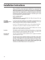
Unpack the components from inside the grill and oven: Check that the
following parts are present.
Grill pan and grid
Oven shelves (2)
Battery 1.5V
Aluminium burner bodies (4)
Stability Bracket
Pan supports (2)
Enamelled discs (4)
Literature
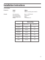
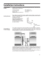
The cooker must be fitted with a stability device firmly secured to the
fabric of the building. One of the holes in the rear panel can be used to
engage a stability bracket.
The bracket must be
fitted to the wall behind the
cooker. The diagram is a
guide to the correct height
at which the bracket should
be from the floor.
155mm
Floor to bracket.
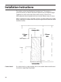
The cooker is designed to match the depth of standard 600mm worktops.
An adaptor backplate should, therefore, be fitted within the shaded area
shown to allow the cooker to be pushed fully to the wall. If a forward
facing backplate is used, it must be chased into the wall.
250
250
550
680
Connecting To
The Gas Supply
Connection to the cooker should be made with an approved
appliance flexible connection to BS 669. A length of 0.9 to 1.25m is
recommended. The length of hose chosen should be such that when the
cooker is in situ, the hose does not touch the floor.
The temperature rise of areas at the rear of the cooker that are likely to
come in contact with the flexible hose do not exceed 70oC.
21