1
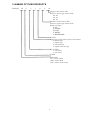
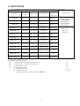
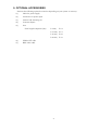
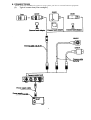
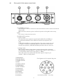
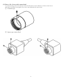
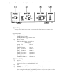
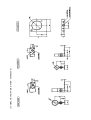
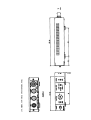
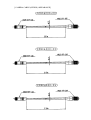
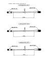
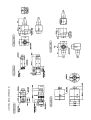
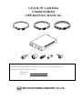
CCD B/W CAMERA
CS4000 SERIES
OPERATION MANUAL
For Customer Use:
Enter below the Serial No. which is located on the rear panel of the camera control unit.
Retain this information for future reference,
Model name.
Serial No.
TOKYO ELECTRONIC INDUSTRY CO.,LTD.
1. FEATURES
(1)
(2)
(3)
(4)
Compact and light weight camera head.
Equipped with AGC (Automatic Gain Control) which allows wide dynamic range from
bright to dark subjects.
Equipped with RTS (Random Trigger Shutter) which allows free timing capture with stable
SYNC.
Available external SYNC (HD/VD, YS, SYNC) operation.
2. PRECAUTION
(1)
(2)
(3)
(4)
(5)
(6)
(7)
(8)
(9)
(10)
This equipment should be used with DC12V only.
To prevent electric shocks and fire hazards, do not use any other power source.
The CS4000 series are designed to be used with EIA B/W television signals.
It cannot be used for playback with a television of a different standard.
Please handle the equipment carefully.
Do not point your camera lens directly into sunlight or strong artificial light.
This might cause irreparable damage to the image sensor.
Also, be sure to use the lens cap when the camera is not in use.
Do not expose the camera unit to high temperatures. For example, do not place it near a
stove for long periods, or in direct sunshine or in a car in hot weather. Heat may cause
some malfunction.
Keep the camera clean. Dust can damage the camera and cause trouble in moving parts.
Take particular care to avoid the entry of sand or grit when changing the camera lens.
Avoid jolting the equipment or exposing it to vibration.
Never attempt to dismantle the equipment.
Avoid folding or stretching the camera cable or other connection cable between equipment.
When the cabinet is dusty, clean by gently wiping with a soft cloth And avoid the use of strong
cleaning agents such as benzene or alcohol as they may damage the cabinet.
1
3. NAMING OF THIES PRODUCTS
(Example)
CS
4
3
1
0
V
-01
Length of the camera cable
(Only for square type camera head)
02: 2m
03: 3m
05: 5m
Direction of the camera cable
(Only for square type camera head)
(From rear sight)
Z: UP
X: DOWN
W: LEFT
Y: RIGHT
V: BACKWARD
"0" fixed
Appearance of the camera head or lens mount
0: Round type
1: Square type
2: C-mount type
3: Square C-mount type
Size of CCD
2: 1/2 inches
3: 1/3 inches
"4"fixed
Trade mark
CS : camera system
CSH : camera head
CSU : camera control unit
2
4. CONSTITUTION
The constitution (the combinations of the camera head and the camera cable) is as following.
Camera head
Appearance
Camera cable
Size of the
Type name
Appearance
Lens mount
of the
CCD
camera head
2m: (CPRC4000-02)
M15.5 P0.5
CSH4200
1/2 inches
Ø 17mm
Round type
(CPRC4100-02)
(male screw)
3m: (CPRC4000-03)
CSH4220
1/2 inches
Ø 29mm
C-mount
Round type
(CPC4100-03)
5m: (CPRC4000-05)
M10.5 P0.5
CSH4300
Winches
Ø 12mm
Round type
(CPC4100-05)
(male screw)
CSH4230V-□□
1/2 inches
30 X 30mm
C-mount
Square type □□:Cable length
(1) 02: 2m
(2) 03: 3m
CSH4230W-□□
1/2 inches
30 X 30mm
C-mount
Square type
(3) 05: 5m
CSH4230X-□□
1 /2 inches
30 x 30mm
C-mount
Square type
CSH4230Y-□□
1/2 inches
30 X 30mm
C-mount
Square type
CSH4230Z-□□
1/2 inches
30 x 30mm
C-mount
Square type
CSH4310V-□□
1/3inches
20 X 20mm
CSH4310W-□□
1/3inches
20 x 20mm
CSH4310X-□□
1/3inches
20 X 20mm
CSH4310Y-□□
1/3inches
20 X 20mm
CSH431OZ-□□
1/3inches
20 x 20mm
M10.5 P0.5
(female screw)
M10.5 P0.5
(female screw)
M10.5 P0.5
(female screw)
M10.5 P0.5
(female screw)
M14.5 P0.5
(fee screw)
STANDARD CONSTITUTION
(1)
Camera head (without lens) with head cover
(2)
Camera cable
2 m/3m/5m (Optional)
(3)
Camera control unit
(4)
Provided accessories
① Operation manual
② Screws to fix a lens
(Only for square type camera head and CSH4220)
3
Squaw type
Square type
Sq
Sq
Square t)"
1 pc
1 pc
1 pc
1 pc
1 or 2 pc
5. OPTIONAL ACCESSORIES
Purchase the following optional accessories depending on your system as necessary.
(1)
Cable for power supply
(2)
Connector for power input
(3)
Camera lead mounting kit
(4)
C-mount adapter
(5)
Lens
Focal length & Aperture (Iris)
f=4 mm,
F 2.2
f=7.5 mm, F 1.6
f=15 mm, F 2.0
f=24 mm, F 3.6
(6)
SYNC OUT cable
(7)
BNC video cable
4
6. CONNECTIONS
When install the CS4000 series camera to your system, you have to connect between equipment.
(1)
Typical connection (One example)
5
(2)
Rear panel of the camera control unit
① [CAMERA] connector
This connector is used to connect the camera head and the camera control unit with the
camera cable.
When insert the connector, please confirm the position of the guide and screw up
tightly.
If it is loose, it may cause some noise.
② [SYNC OUT] connector
(1) Pulse outputs
Use them when other equipment required pulses (HD, VD, and SYNC) to
be synchronized with the camera. When the external sync-operation, the
pulse
of HD, VD and SYNC are regenerated inside of the camera control unit and
are output to each pins as followings. When no pulses from outside (at the
internal sync-operation) , HD,VD and SYNC generated inside are come out.
(2) Trigger input
When required random trigger shutter operation between other equipment
input RTS pulse from pin number 1. And short pin number 2 to pin number 4
or set the shutter switch on the front panel to ” RDM “.
Then index pulse to be synchronized with video signal is output to pin
number 3 . (Refer to Timing Chart)
① TRIG INPUT
② MODE SELECT
③ INDEX OUTPUT
④ GND
⑤ VIDEO OUTPUT
⑥ GND(VIDEO)
⑦ SYNC OUTPUT
⑧ GND(SYNC)
⑨ HD OUTPUT
⑩ GND(HD)
⑪ VD OUTPUT
⑫ GND(VD)
The alignment of the receptacle dip posts
12 terminals (female)
6
(rear view)
③ [DC IN / VIDEO OUT] connector
(1) DC12V input
Connect pin number 2 and / or 11 for DC12V (HOT) and pin number 1 and / or 10
for GND.
(2) Video output
Composite EIA video output (VS) is output from pin number 4(HOT) and
pin number 3(GND).
(3) Input pulses for external sync
When required external sync-operation between other equipment, use either one of
pulse for HD/VD, VS or SYNC. And input HD pulse form pin number 6-5 (GND)
and VD from pin number 7-8 (GND) for HD / VD external sync-operation.
And input VS or SYNC from pin number 9-8(GND) for external sync operation
by VS or SYNC.
① GND
② DC 12V INPUT
③ GND(VIDEO)
④ VIDEO OUTPUT
⑤ GND
⑥ HD INPUT
⑦ VD INPUT
⑧ GND(VD)
⑨ VS(SYNC) INPUT
⑩ GND(VS)
⑪ DC12VINPUT
⑫ GND
The alignment of the receptable dip
t
12 terminals (male)
(rear view)
④ [VIDEO] connector
Composite EIA video output(VS) is come out from this connector which is employed BNC
type.
7
(3) How to fix a lens to this camera head
To prevent loosing of the lens from the camera head because of some vibration or shock, fix the lens to
this camera head with screw tightly. The screw is provided with this camera head.
① C-mount type
② Square type camera head
8
7. CONTROLS AND ADJUSTMENTS
Get to know the name and function of every part of this camera.
That way, you can take advantage of every application to take beautiful pictures.
(1)
Lens
* Lens is an optional accessory.
① Iris ring (Aperture ring) for use at manual operation.
To reduce aperture, rotate the iris ring toward CLOSE (clockwise).
To increase aperture, rotate the iris ring toward OPEN (counterclockwise).
Adjust the lens aperture according to the amount of light entering the lens so that
correct exposure is obtained.
② Focus ring
Take the focus with the ring to get a sharpest picture.
*The CS4000 series camera is fitted with the "C" type lens mounting system using the
C-mount adapter. This system allows you to use any lenses belonging to the "C" mount
lens group according to your applications.
(2)
Camera cable
You can use 2m, 3m or 5m cable without any adjustments. Do not use any other length of
the camera cable.
9
(3)
Camera control unit (front panel)
① [POWER]
A power on/off switch when power is turned on, the pilot lamp on the power switch
will light.
② [SHUTTER]
a)
Toggle switch .
[NOR]: Normal mode.
[RDMJ: Random trigger shutter mode.
b)
Rotary switch
This switch is shutter speed selector
Shutter speed
Normal mode RTS mode
[OFF] :off
1/60 sec.
[F.L.] :1/100 sec.
1/100 sec.
[50/60] :1/60 sec.
1/60 sec.
[125] :1/125 sec.
1/125 sec.
[2503 :1/250 sec.
1/250 sec.
[500] :1/500 sec.
1/500 sec.
[1000] :1/1,040 sec.
1/1,000 sec.
[2000] :1/2,000 sec.
1/2,000 sec.
[4000] :1/4,000 sec.
1/4,000 sec.
[10000] :1/10,000 sec.
1/10,000 sec.
③[GAIN CONT]
a)
b)
c)
AUTO
When AGC (Automatic Cain Control) is to increase or decrease sensitivity
electrically to get the comfortable video level.
STD
Normally, put it [STD] position. The gain is fixed.(0dB)
MANU
If the illumination of the subject is not sufficient and the picture on the monitor is
dark or bright, set this switch to [MANU] position. And you can adjust the video
level with the knob of [GAIN].
10
④[GAMMA]
Generally, TV camera provides gamma correction in the video-process amplifiers, which make up
apposite side for non linear characteristics of image signals based on CRT’s electron gun in TV
receiver and the total performances of the video system have linear (GAMMA: 1.0).
Usually, use the gamma correction “ ON “ position, which set the standard camera gamma-value
of 0.45.
And if required gamma " OFF " (gamma value: 1.0) with the system, turn it to " OFF " position.
11
8.
SUPPLEMENTAL INFORMATIONS
(1)
Illuminant for better picture
(2)
Smear
When the strong light hits the CCD image sensor, the image of bands in vertical direction
tray appear above and under the spot. This is called smear. Especially if the camera
shoots under the noon sun or its reflections, a candlelight in the dark, or headlights of cars,
these smears may stand out in the picture.
The CCD used in the CS4000 series is designed as very strong against the smear.
However, you may watch out for smear when shooting involves very strong light sources.
(3)
Lenses
Generally, there are many kind of lenses for the video camera on the market, for example,
different aperture (iris), different focal distance, zoom lenses and so on. Those having a
shorter fool distance are called “wide-angle” lenses, and those having a longer focal
distance are called “telephoto”.
Lenses of different focal distances have special characteristics and you can take advantage
of these in shooting.
Anyhow, make choice of the most appropriate lens for your application or system.
12
9.
TROUBLE-SHOOTING GUIDE
What may initially appear to be trouble is not always a real problem. Make sure first according to
the following table before requesting service.
Symptoms
Check points
Power
No power is supplied
*Have you connected power cord correctly ?
Halation or black-out occurs
*Check whether the iris ring has accidentally moved out of the
normal position.
13
10. SPECIFICATIONS
(1)
(2)
(3)
(4)
(5)
(6)
(7)
(8)
(9)
(10)
(11)
(12)
(13)
(14)
(15)
TV system
EIA
Image sensor
Interline CCD
768(H) x 494(V)
①Active pixel
②Active image area
a)
1/2 inches
6.45mm(H) x 4.84mm(V)
b) 1/3 inches
4.88mm(H) x 3.66mm(V)
Number of scanning lines
525 lines
Scanning system
2 : 1 interlace
Sync. System
Internal / External
Scanning frequencies
15.734 kHz
① Horizontal drive
59.94
Hz
② Vertical drive
Aspect ratio
4:3
Illumination
① Standard (F11, 3,000K, 100%output)
a)
1/2 inches(CSH4200)
1,200 lx
b)
1/2 inches(others)
800 lx
c)
1/3 inches
1,500 lx
②50% Output (F1.4, 3,000K, γ :ON,AGC:AUTO, approx. 50%output)
a)
1/2 inches(CSH4200)
2.5 lx
b)
1/2 inches(others)
1.7 lx
c)
1/3 inches
3.0 lx
③ Minimum (F1.4, 3,000K, γ ON, AGC:AUTO, approx. 25%output)
a)
1/2 inches(CSH4200)
1.5 lx
b)
1/2 inches(others)
1.0 lx
c)
1/3 inches
2.0 lx
Video output
VS=1.0 Vp-p/75 Ω,positive polarity
Resolution
570 TV lines
①Horizontal
350 TV lines
②Vertical
S/N (luminance)
50 dBp-p/rms or more
External sync. Input HD
4±2Vp-p/High impedance, negative polarity
15.734kHz±1%
VD
4±2Vp-p/High impedance, negative polarity
59.94Hz±1%
SYNC
2±1Vp-p/75 Ω, negative polarity
Horizontal: 15.734kHz±1%
Vertical:
59.94Hz±1%
VS
1.0Vp-p/75 Ω, positive polarity
Horizontal: 15.734kHz±1%
Vertical:
59.94Hz±1%
Signal output
TTL level, negative polarity
① HD
TTL level, negative polarity
② VD
TTL
level, negative polarity
③ SYNC
Gamma correction
ON(0.45) / OFF(1.0) selectable
Gain control
AUTO/STD/MANU
Video level can be adjustable by [GAIN]
potentiometer when MANU.
14
(16)
Electronic shutter
(17)
Random trigger shutter
① Trigger pulse input
② Shutter speed
③ Video signal output field
④ Index pulse output
Power source
Power consumption
Ambient condition
① Temperature
②Humidity
Camera cable
Dimensions
Weight
① Camera head
a)
CSH4200
b)
CSH4220
c)
CSH4300
d)
CSH4310
e)
CSH4400
f)
CSH4410
②Camera control unit
a)
CSU4000
Emission
(18)
(19)
(20)
(21)
(22)
(23)
(24)
Shutter speed: 10 position
OFF
F.L(1/100 second)
1/60 selectable
1/125 selectable
1/250 selectable
1/500 selectable
1/1,000 selectable
1/2,000 selectable
1/4,000 selectable
1/10,000 selectable
TTL level, Down edge
Fixed at selected speed of electronic shutter
Odd field feed
TTL level, effect of positive polarity
DC 12V±10%
approx. 400mA
0~+40°C
10~90%Rh
2m/3m/5m
refer to the apperances
approx. 16 gr.
approx. 45 gr.
approx. 11 gr.
approx. 15 gr.
approx. 9 gr.
approx. 15 gr.
approx 600 gr.
VCCI
Class A
Design and specifications subject to chop without notice.
15
11. MAINTENANCE
(1)
(2)
(3)
(4)
(5)
(6)
(7)
(8)
Cleaning should be done only after units have been disconnected.
When the cabinet is dusty, clean by gently wiping with a soft cloth.
And avoid the use of strong cleaning agents such as benzene or alcohol as they may
damage the cabinet.
If malfunctioning occurs, stop using equipment immediately and consult TELI-service shop,
the dealer purchased from or qualified personnel.
Upon completion of any service or repairs, request the service technicians that only Factory
Authorized
Replacement Parts that have the same characteristics as the original part’s were used, and
that routine safety checks have been performed to determine that the video product is in
safe operating condition.
Unauthorized parts may result in fire, electrical shock, or other hazards.
When you send the product to a service center, you must use the original carton box and
packing materials, then insert the original carton box containing the unit into another carton,
using more packing materials.
When requesting services, the following information is necessary.
Your name, address and telephone number.
Model name, serial number and date of purchase.
Explain the damage, malfunction or other symptoms as precisely as possible.
The minimum availability period for repairs (parts necessary to keep unit functioning) is 8
years after the end of producing the model.
If you have any question regarding after-sales service, etc., please contact the nearest
service center.
16
12. APPEARANCES
See page 18~21.
17
[ CAMERA MOUNTING KIT (OPTION) APPERANCE]
[ CAMERA CONTROL UNIT APPERANCE]
[ CAMERA CABLE (OPTION) APPEARANCE]
CAMERA CABLE (OPTION) APPEARANCE
[ CAMERA HEAD APPERANCE]