1
IP Telephony Engineering Principles
Agenda
•
•
•
•
•
•
•
Network Region Design
IP Telephone Operation
QOS across the Enterprise
Bandwidth Considerations
Call Admission Control
Media Encryption
IP Trunking & PSTN Fallback
Note: Discussion will
focus on H.323 and not
SIP but the concepts
with respect to QOS are
the same with different
ports in some cases.
Typical IP Telephony WAN deployment
MPLS (FR)
Based
Network
Sample IP Connectivity and Functions
C-LAN (signaling)
IP
IP Phone
Media Processor
(voice stream/
DSP farm)
PSTN
IP Phone
PSTN
Integrated CC-LAN
& Medpro
IP
TN Gateway IP Interfaces
IPSI Card: IP Server Interface Card
•Provides Control Interface for MG
•Delivers Tone and Call Classifications Resources
C-LAN: Control LAN card
• Handles signaling for IP Phones and Trunks
• Handles signaling for Adjuncts (Audix, CMS)
•Allows Remote Administration
•Dedicated resource, design to 300 sessions
MedPro Card: Media Processor Card
• Converts TDM based media in IP based
• Supports Codecs: G.711, G.729, G.723
• Supports from 32 to 64 simultaneous sessions
• Dynamically allocated resource
H.323v2 Protocol Stack
Control
Data
Audio/Video
Control
Audio Video
Control
Gatekeeper
G.7XX H.26X
H.225 H.245 T.120
RTCP
RTP
TCP
UDP
IP
Registration
Admission
Status
(RAS)
Network Region Design
Network Regions
• Binds Endpoints to a Specific Location
• Dial Plan adjusted by Network Region (useful for E911, local calling)
• Determines what CODEC needs to be used for Intra-Network-Region
calls
• Determines what CODEC needs to be used for Inter-Network-Region
calls
• Can determine what VoIP Monitor Manager is used
• Determines what QOS settings to be used
–Customize layer 2, 3, & 4 settings
WAN and Network Regions
192.168.1.0
1
PSTN
C-LAN
G.729
LAN/WAN
MedPro
2
G.711
192.168.2.0
FROM
(TO Address
192.168.1.0 _
192.168.2.0 _
_._._._
_._._._
Subnet
or Mask)
24
24
_
_._._._
_._._._
_
_._._._
_._._._
_
Region
1
2
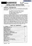
DSP Resource Allocation by Call Type
Codec/ Call Type
G.711
Pass-through
Capacity Points
1
Clear Channel
G.729 &
G.723 VoIP
Fax Relay
Modem Relay
T.38
2
4
Max Calls / Media Processor
W/o encryption
W/ AES
encryption
64 /
(TN2302&MM760)
48/ (TN2302 &
MM760)
32 / G350
24/ G350
32 / (TN2302 &
MM760)
24/ (TN2302 &
16 / G350
12/ G350
16 / (TN2302 &
MM760)
Not applicable
MM760)
8 / G350
Notes: (A) TN2302AP < HV10 (aka TN Media Processor) do not support data transmission other than
Avaya patented transport for fax.
(B) A G700 Media Gateway has the equivalent of an MM760 embedded in the system. The G350
has the equivalent of half that.
DSP Allocation Rules
TN Media Processor already in use by the phone
H.248 MG already in use by the phone
Preferred region and preferred PN, TN Media Processor
Preferred region in any PN, TN Media Processor
Preferred PN in any region, TN Media Processor
Preferred region, H.248 MG
Any region, TN Media Processor
Any region, H.248 MG
Decreasing Priority
1.
2.
3.
4.
5.
6.
7.
8.
CLAN Design Considerations
• Provide logical mapping from IP Telephone NR to CLAN
pool regions
• Maximum of 300 registered endpoints per CLAN even in
failover scenario (N+1)
• Have at least 2 CLANs for MGC list; for max CLAN
resiliency use 3
• Maximize operational efficiency by minimizing the
number of locations in each pool
• Keep it simple or make it manageable
Designing for CLANs By locations
IP Telephones
NR 101
NR 1
CLAN Resource
NR 102
H.248 Media Resource
TN Media Resource
NR 103
Designing for CLANs -- Logical Pooling
IP Telephones
CLAN Resource
NR 201
H.248 Media Resource
TN Media Resource
NR 202
NR 101
NR 102
NR 1
NR 103
CLAN Pooling
Benefits
Negatives
• More Granular Registration
Control
• Better Trouble Isolation
• Better recovery control
• Greater flexibility in the
application of network policy
• CLANs registrations will not be
balanced across network
regions
• Need more CLANS
• Greater operational complexity
• Operational changes may
require re-design
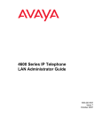
NR Design without “Ghost” Region
Location 1/NR 1
Controlling S8700 IP
Connect and 100 IP
Telephones
1.544M
MPLS
Based
Network
Location 2/NR2
G700 MG with LSP and 50
IP Telephones
1024K
1024K
The WAN link speeds
for NR 2 and 3 are
misrepresented by the
CAC values.
Location 3/NR3
G350 MG with LSP and 25 IP
Telephones
512K
512K
“Ghost Regions”
• In order to correctly define the WAN link for each site, a
“Ghost Region” is configured so the CAC values are correct
– All 3 of our Network Regions in the previous example would directly
connect to the Ghost Region
• The interconnection from NR 1 to NR 2 would intervene through the
Ghost Region
– By using the Ghost Region configuration, the CAC bandwidth limits
would be correctly defined for the actual WAN link and prevent
over subscription
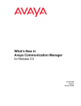
NR Design with“Ghost” Region
Location 1/NR 1
Controlling S8700 IP
Connect and 100 IP
Telephones
1.544M
MPLS
Location 2/NR2
G700 MG with LSP and 50
IP Telephones
Location 3/NR3
NR 5
G350 MG with LSP and 25 IP
Telephones
1024K
512K
The MPLS WAN is now represented by
NR 5 in Communication Manager and the
topology is correctly depicted by the
CAC values
Administration of GR
Network Region 5 is used as
the Ghost Region (for actual
implementations, a higher
region may be more
appropriate to allow for
scalability).
The only region that NR’s 13 directly connect to is NR 5
and intervene to the other
regions. There are no actual
resources in NR5, it is more
of the WAN cloud
representation.
All WAN connections are
now correctly defined and
Communication Manager
has the correct
interpretation of the
topology.
IP Telephone Operation
Implementation Overview
802.1p/Q,
DSCP, Port
Range
C-LAN
“Data”
Data” VLAN = 10
“Voice”
Voice” VLAN = 11
Tagged and
Untagged Packets
Untagged Packets
Media
Processor
Tagged and
Untagged Packets
Untagged Packets
PSTN
802.1p/Q,
DSCP, Port
Range
Power over Ethernet –
How does it Provide Power?
PoE Power Source
• IP Phones have been 802.3af
compliant for years
• Performs phone detection
• It applies power to the endpoint
(IP phone) using the signaling
pairs
• If the endpoint is removed or
the link is interrupted
– Power is shut off
– the detection process starts
again
1. Line inquiry
2. Endpoint
‘sends’ answer
3. Power supply
calculation
4. Power opened
on port
Power ConsumptionClass 2
Watts (IEEE 802.3af -2003@ 48V)
Class 3
4630SW
4625SW
4621SW/
4622SW
4620SW
4620SW
4620
4610SW
4602SW
4601/4602
Typical
3.5
4.1
4.0
7.7
5.9
4.6
4.9
7.8
11.8
Worst
Case
4.6
5.0
6.0
9.9
8.0
5.75
6.45
9.42
12.9
Typical is measured off-hook. Worst Case is analytical. Except the 4601 and 4602
all telephones had a PC attached at 100Mbps. The EU24 adds less than 1W to the
4620 and 4620SW numbers. The EU24BL can not be used with POE, use the
1151B. The 4620SW CR can be identified by the ethernet jacks that point down,
rather than directly back out of telephone.
DHCP Process – Dual VLAN
Offers:
-IP ADDR
-Subnet Mask
-Default Gateway
DHCP Discover
Offer IP address in VLAN 10
DHCP Server
User PC
DHCP Discover
Offer IP address in VLAN 10
DHCP Server
DHCP Release
Offers:
-IP ADDR
-Subnet Mask
-Default Gateway
-Site Specific Option (176):
-GateKeeper IP Addr (8)
-GateKeeper Port
-QoS Parameters:
-802.1Q = 1
-VLAN = 11
-802.1p = 6
-TFTP Address (8)
DHCP Server
DHCP Discover Using VLAN Tagging (11)
Offer IP address in VLAN 11
Once the phone knows
what the voice VLAN is,
it will boot into that
VLAN first
DHCP Server
IP Phone registration
Process
DHCP Discover
Offer
DHCP Server
TFTP Get
Offers:
-IP ADDR
-Subnet Mask
-Default Gateway
-Site Specific Option:
-GateKeeper IP Addr (8)
-GateKeeper Port
-QoS Parameters
-TFTP Address (8)
TFTP Puts:
-Boot Code (First Time)
-Application Code (First Time)
-Config (e.g. QoS)
TFTP Put
TFTP Server
Enter Extension
Enter Password
Registration, Admission, Status
H.323 and Feature Functionality
Validates:
-Extension
-Password
Provides:
-Access to medias
-Feature / Functionality
DHCP Considerations
• Telephone Firmware 2.1+ offers optional use of IP address
after lease expires
– Does not protect against power failure or reboot
– Based on administrable DHCPSTD parameter
– DHCPSTD = 0 means “Despite the DHCP Standard, continue using
the current IP address after the lease expires, but:
• Send DHCPREQUEST about every minute
• Send ARPREQUEST every 5 seconds
• If ARP REPLY received, set IPADD to 0.0.0.0 and re-initiate DHCP
Discovery”
– DHCPSTD = 1 means “Follow the DHCP Standard (RFC 2131,
Section 4.4.5); give up the IP address immediately if DHCP lease
expires”
DHCP Considerations
• Each subnet requires a DHCP scope.
• For clients not on the same subnet as the DHCP server, enable DHCP
relay on the router interface for the client subnet (i.e. “ip helperaddress”)
• Embedded DHCP server within G350 to support IP phones and local IP
stations
• No plans to support G700 DHCP
• Can use local router as a DHCP server
service dhcp
ip dhcp pool “Miami branch office"
network 10.10.10.0 255.255.255.0
default-router 10.10.10.1
lease 120
option 176 ascii MCIPADD=X.X.X.X,MCPORT=1719,TFTPSRVR=X.X.X.X
ip dhcp excluded-address 10.10.10.1
TFTP Server
• Used for upgrades and optional configuration files
• Not a point of failure for basic telephony operation
• Possible point of failure for additional features
– Review each configuration option to be used in order to
determine impact of failure
• Embedded TFTP server within G250/G350 to optimize
local IP-phones upgrade process
– Limited space in NVRAM
What happens during Registration?
•
•
•
•
Registration starts, GRQ, GCF, RRQ
Phone asking user for Login (extension) and password
Phones sends request for registration for the extension
Server sends to the phone an encrypted message to
validate password
• Password is validated, Server sends a RCF, and features
to the phone and all relevant timers
• Phone sends the supported CODECS and other relevant
parameters
• Based on the C-LAN or the Phone’s IP address, it is set
to a specific Network Region
H.323 Registration Messages
IP Telephone prompts
for Extension and
Password
Gatekeeper
Endpoint
GRQ
GCF/GRJ
Gatekeeper returns IP registration
address to use
(CLAN Load Spreading)
RRQ
RCF/RRJ
Gatekeeper returns
Alternate Gatekeeper Addresses
URQ
UCF/URJ
CLAN Load Spreading
• Communication Manager sends as the RAS address in the
GCF the IP address of a CLAN in the same network region
as the CLAN that received the GRQ.
• Communication Manager software will select the
registration address in a cyclical fashion.
• Use this ability to balance registration across multiple
CLANS.
• IP endpoints will accept an address in the
GCF and use it for that registration.
• Balancing only occurs during registration; phone does not
change CLANs during normal operaion
H.323 Signaling Messaging
Communication Manager -- IP Station
Signaling
H.225 RAS (Registration
Admissions Status)
C-LAN
DCP Call Control
(tunneled over H.323)
H.323 Call Control
H.245 Media Control
Audio Path
MedPro
UDP
TCP
Alternate Gatekeeper
Works similarly for
H.248 controlled
GWs
LAN/WAN
The phone tries to
register with the
second GK on the list,
if that isn’t available it
continues looking
through the list until it
successfully finds a
GK.
Upon first boot
telephone registers with
a C-LAN that it has
received via DHCP.
The CLAN tells the
phones about the
alternate gatekeepers
available to the phone.
When the first re-registration
message is missed the phone
accelerates the rate of
sending those message until
X consecutive messages are
missed at which point . . .
Avaya IP Telephone Use of Gatekeeper
List
• IP Telephone looks at DHCP list and then the RAS list received from
Communication Manager software to look for Alternate Gatekeeper
addresses
• IP Telephone cannot register with LSP until an H.248 MG registers
• IP Endpoints now know about S8300(LSP) though DHCP or RAS
process
• Communication Manager provides LSP addresses in RCF based on IP
Phone Network Region.
• Need to administer each LSP that needs to register with S8700
(“change lsp” command)
• A network-region can have up to 6 LSPs.
46XX GK Search : What triggers a
phone to search for another GK?
Idle Traffic Interval
Default Settings:
Idle Traffic Interval -- 20s
Keep Alive Interval – 5s
Keep Alive Count – 5
Keep Alive Interval
Endpoint
KA
KA
ACK
No ACKs
Keep Alive Count
Retry
KA
KA
Gatekeeper
(aka) CLAN
46XX GK Search
Unsuccessful Discovery Timer (Phone)
ACM Drops
endpoint’s
call state
H.323 Link Loss Delay Timer (ACM)
Primary Search Timer (Phone)
Alternate
Gatekeeper
List
On-hook retry
Phone
Reboots
Off-hook retry
CLAN1
CLAN2
CLAN3
LSP1
LSP2
Repeat
Note : In this example, the Active Gatekeeper (Server) has 3 CLANs
And 2 LSPs
Timer parameters can be found in
“system-parameters ip-options” and
“ip-network-region” forms. LSP list is
found in IP-network-region
During signaling channel loss active
calls are preserved. Endpoint attempts
to re-register with the original servicing
gatekeeper during call duration
46XX GK Search
Server/CLAN
IP Telephone
TCP KA
TCP ACK
20s on 46XX
TCP KA
TCP ACK
20s on 46XX
TCP KA
Outage:
Server
Or
Network
TCP KA
TCP KA
TCP KA
TCP KA
TCP KA
5s once 1st
TCP KA
Is missed
Phone
Checks for
new GK
Timers in Operation (Link Recovery)
PST
Begins
Scenario 2: Active IP call to PSTN
H.248
LL
Begins
1)
Wan goes down for 2 minutes.
2)
During outage, gateway KAs
expire after ~45 seconds, primary
search time begins on gateway.
3)
H.248 link loss timer begins
shortly after gateway primary
search timer (seconds).
H.323 Link Loss = 6 min
H.248 Link Loss = 6 min
4)
H.323
LL
Begins
IP Phone- KAs also expire
after ~45 seconds, and H.323
link loss timer also begins
shortly after gateway primary
search timer (seconds).
Gateway h.248 App. Keep Alive = every 14 seconds, 45 second retry interval.
IP Phone TCP KA = every 20 seconds, 5 retries, 5 seconds each.
PST
Begins
H.323 PST = 5.5 min
H.248 PST = 5 min
5) Because WAN recovery occurred
prior to the timer expiring phone call
is re-established “in progress”
Timers in Operation (Timers Expire)
PST
Begins
Scenario 2: Active shuffled IP call: IP
Phone-1 to IP Phone-2.
H.248
LL
Begins
1)
Wan goes down for 8 minutes.
2)
During outage, gateway KAs
expire after ~45 seconds, primary
search time begins on gateway (5
minutes). No CLANs to find within
first 5 minutes.
H.248 link loss timer begins
shortly after gateway primary
search timer (seconds).
3)
H.323 Link Loss = 6 min
H.248 Link Loss = 6 min
4)
H.323
LL
Begins
IP Phone- KAs also expire
after ~45 seconds, and H.323
link loss timer also begins
shortly after gateway primary
search timer (seconds).
Gateway h.248 App. Keep Alive = every 14 seconds, 45 second retry interval.
IP Phone TCP KA = every 20 seconds, 5 retries, 5 seconds each.
PST
Begins
H.323 PST = 5.5 min
H.248 PST = 5 min
Timers in Operation (Timers Expire)
Scenario 2: Active shuffled IP call: IP
Phone-1 to IP Phone-2.
5)
6)
7)
H.323 Link Loss = 6 min
H.248 Link Loss = 6 min
GW
Registers
w S8300
Gateway primary search timer
expires after 5 min, gateway
moves beyond TP, gateway
registers to LSP, and MGC resets.
Phone Primary Search Timer
expires after 5.5 minutes
(transitions to LSP)
H.248 an H.323 Link Loss timers
expire. Resources are liberated
on primary call server. Calls can
no longer be re-instated.
WAN returns after 8 total
minutes. Phones now
registered to discrete call
processors.
Gateway H.248 App. Keep Alive = every 14 seconds, 45 second retry interval.
Phone
Registers
w S8300
H.323 PST = 5.5 min
H.248 PST = 5 min
8)
IP Phone TCP KA = every 20 seconds, 5 retries, 5 seconds each.
Future: Connection
Preserving Transition
QOS Across the Enterprise
Voice Application in a Data Network
What happens when you put voice in your data network?
•Data Communication is Bursty in Nature
•Packet Networks are Asynchronous
•Voice is a Real-Time Application
•Voice Transmission is Synchronous
Class of Service –
Prioritization (tagging)
What is the solution?
•A Voice ready Network needs QoS
•Long Term Solution should be Policy Based
Avaya QoS solution:
Quality of Service –
Processes in place to
assure the prioritized
packet get to destination
•Layer 2 : 802.1p/Q – VLAN and priority inside the VLAN
•Layer 3 : DiffServ (TOS byte), RSVP – WAN queuing, Bandwidth
Reservation
•Layer 4 : UDP Port Range – No suggested range
•100% Standards Based
Standards Based Class of
Service
Layer 2
(Ethernet)
Layer 3
(IP V4)
MAC Layer Header
DAddr
SAddr
Layer 4
(TCP or UDP)
Network Layer Header
802.1p,Q
802.1p specifies
priority desired
TOS
Transport Layer Header
SAddr
DAddr
TOS field specifies service level
desired
Saddr/Daddr or Saddr/Daddr/Port #
identifies RSVP flow
Data
Port Number
Port Number identifies
application/session
Protocols and Ports
Registration (H.225 RAS) = UDP 1719
Signaling (H.225 Q.921) = TCP 1720
Voice (RTP) = UDP 2048-65535 (configurable)
Media Gateways (H.248) = TCP 2945
Port networks (“classic” media gateways) = TCP 5010
QoS Requirements
•Delay (one way between endpoints):
•ITU spec is 150ms or less
•Avaya recommends 80ms or less for “business quality audio”
•Delay over 150ms could be acceptable depending on customer
expectations, codec, etc.
•Delay over 250ms causes “talk over” problems
•Jitter (variation in delay):
•Less than 20ms recommended
•Defaults can handle up to 30ms (dependent on sampling rate)
•Packet loss:
•Less than 1% recommended
RSVP - Resource reSerVation Protocol
• RSVP is a QoS signaling protocol
• RSVP/Integrated-Services provides protection for the voice
bearer channel in a loaded or congested network.
• IP Phones/Gateways request the network routers to reserve
bandwidth.
• Routers act upon the request to allocate bandwidth according
to QoS request.
• When bandwidth is reserved, the call is protected against
other network traffic.
• This ensures good voice quality for the users.
RSVP in action
Non-RSVP
IP Phone
Ethernet
RSVP
IP Phone
Non-RSVP
IP Phone
LAN
WAN
LAN
Ethernet
RSVP
IP Phone
Network traffic
generator
Network traffic
generator
1) RSVP enabled phone call is established.
2) RSVP disabled phone call is established.
3) When the network is loaded with emulated voice traffic:
RSVP enabled bearer channel is protected exhibiting good voice quality
RSVP disabled bearer channel is not protected exhibiting bad voice quality
When to enable RSVP
• If the customer wants a scenario where N calls get
guaranteed service and the N+1th call competes with
everything else, then RSVP is the best solution.
• But if the customers want a scenario where N calls get
guaranteed service and the N+1th call is not permitted
to go through, then Call Admission Control schemes
need to be used.
So What If I’m Experiencing Poor
Quality Voice
• Factors that need to be examined
–
–
–
–
–
Network Metrics (Packet Loss, Jitter, Latency)
Trunk connectivity (Digital, Analog)
DSP resources (Medpro, Gateway)
End User Device (Headset, Terminals)
Environmental
• Psychology may be a factor
– People are more alert after a change
– Feature Issues
Symptoms & Possible Causes
Symptom
Possible Cause
Echo
Trunks, Latency
Tininess
Packet Loss, Jitter
Static
Packet Loss, Stations
Muffled, Garbled
Stations
Volume Levels
Trunks, Environment, Stations
Clipping, “Breaking up”
Packet loss, Silence Suppression
VoIP Monitoring Manager (VMON)
RTP
RTCP
RTP
RTCP
IP Phone 1234
IP Softphone x5678
VoIP Monitoring Manager (VMON)
RTCP (Real Time Control Protocol) – RFC 1889
QoS Monitoring with VMON
• What it does?
– Record call statistics (delay, jitter and packet loss) on some or all
calls (configurable by network region)
– Real-time view or Historical (up to 30 days at this time). Search
by extension number, time range or IP address
– Configurable SNMP traps for different combinations or jitter,
delay and/or packet loss thresholds
• What do I get out of it?
– Baseline: What did things look like before or after the change?
– Troubleshoot: Comparing different groups of endpoints.
– Proactive Monitoring: Be alerted if service falls below a certain
level.
VoIP Monitoring Manager (VMON)
VoIP Monitoring Manager (VMON)
Bandwidth Considerations
Shuffling
Signaling ~ 50bps
Media ~ 80Kbps
2nd building
PSTN
Call is answered (duration: typically 3 minutes):
Call
inCall
Conference
typically
minutes):
Callisset
up Processor
(duration(duration:
usually
only
1 toendpoints
53sec):
Avaya
sees that
both
are IP, and asks A
Avaya
Processor
knows
that
now it needs
to mix
the calls, so
Caller
hear
dialtone
and
than
ring-back
from the
Tone-Clock
to
pingCall
B, and
vice-versa.
it Answer
redirectsisthe
piece
offthe
thephones
phonesto
and
intovoice
the Media
yes,media
the ACP
tells
send
packets to
Processor
(MedPro)
each other,
but keeps signaling
Conferencing Scenario (Pre ACM 3.0)
NR 2
NR 1
MedPro
Resource
A
MedPro
Resource
A
Digital
Endpoint
IP Endpoint
IP Endpoint
Add 2nd IP Call
NR 2
NR 1
MedPro
Resource
A
Digital
Endpoint
MedPro
Resource
A
IP Endpoint
IP Endpoint
Conferencing Scenario (ACM 3.0 and
NR 2
later)
NR 1
MedPro
Resource
A
MedPro
Resource
A
Digital
Endpoint
IP Endpoint
IP Endpoint
Add 2nd IP Call
NR 2
NR 1
MedPro
Resource
A
Digital
Endpoint
MedPro
Resource
A
IP Endpoint
IP Endpoint
Bandwidth Considerations
• Bandwidth impact on a LAN/WAN depends on
– CODEC used
• G.711 which produces 64Kbps voice samples
• G.729 which produces 8 Kbps voice samples
• G.723.1 which produces 6.3 and 5.3 Kbps voice samples
– Frame size used
• G.711 uses 10ms frames (80 bytes)
• G.729 uses 10ms frames (10 bytes)
• G.723 uses 30ms frames
– Number of Frames per packet
– Protocol Overhead
Minimize # codec sets
LAN Codec Set
(G.711 20ms samples,
modem pass-through)
WAN Codec Set
(G.729 30ms samples,
modem relay)
G.711 Analysis
• G.711 uses 64Kbps voice samples
– 64000bps equals 64 bits per ms
– 64 bits per ms equals 8 bytes per ms
• A G.711 Frame is 10 ms or 80 bytes
• Protocol overhead
Uncompressed Real Time Protocol (RTP)
User Datagram Protocol (UDP)
12 Bytes
8 Bytes
Internet Protocol (IP)
20 Bytes
Layer 1 and 2 Ethernet
26 Bytes
TOTAL
66 Bytes
Ethernet Header Breakdown
• Ethernet has the following components:
Preamble and 1 byte start of frame
delimiter
8 Bytes
Ethernet (Type, MAC SRC, MAC
DST)
14 Bytes
802.1Q (priority and VLAN)
4 Bytes
Data Network Impact of Active G.711 IP
Call
G.711(64Kbps)
Number of 10 ms
Frames per Packet
Packet Size
Audio Payload
Total Packet Size
(Codec Frame size*Packet Size)
(Audio Payload plus packet
overhead)
Total Bandwidth
(Kbps)
1
10ms
80 Bytes
146 Bytes
116.8
62ms
2
20ms
160 Bytes
226 Bytes
90.4
72ms
3
30ms
240 Bytes
306 Bytes
81.6
82ms
4
40ms
320 Bytes
386 Bytes
77.2
92ms
5
50ms
400 Bytes
466 Bytes
74.5
102ms
6
60ms
480 Bytes
546 Bytes
72.8
112ms
(Total Packet Size*8
=bps/packet size)
Target Delay
(msec)
Bandwidth Minimization
• Three approaches to minimize bandwidth
–
–
–
–
Choose a low bit rate audio codec
Combine multiple audio frames into one packet
Suppress transmission of silence
Use header compression
• Lower bit rate codec can degrade quality and increase
processing
• Combining multiple audio frames in one packet
reduces bandwidth required
• Combining multiple audio frames in one packet
increases delay
Bandwidth for Different Size Voice
Samples
Sample
Size (ms)
10
20
30
40
50
60
G.711
96.0
80.0
74.7
72.0
70.4
69.3
G.729
40.0
24.0
18.7
16.0
14.4
13.3
• Default is 20ms (which is the recommended setting for most situations)
• Smaller samples make it less efficient (more bandwidth consumed)
• Larger samples make it more efficient… BUT at a cost….
• Increases latency
• A greater amount of voice is lost if packet loss occurs
Full and Half Duplex Facilities
Full Duplex: Transmit and Receive Simultaneously
(WAN Facilities and Switched Ethernet)
AND
Half Duplex: Can Either Transmit or Receive
(Shared Ethernet)
OR
Bandwidth Impact on Full Duplex
Facilities
CODEC TYPE
(30ms Packets)
G.711
G.729
A and B Both Suppress
Silence
A Suppresses Silence and
B Does Not
Neither End Suppresses
Silence
A Talking to B
A Talking to B
A Talking to B
80 Kbps
80 Kbps
80 Kbps
0 Kbps
80 Kbps
80 Kbps
B Talking to A
B Talking to A
B Talking to A
0 Kbps
0 Kbps
80 Kbps
80 Kbps
80 Kbps
80 Kbps
A Talking to B
A Talking to B
A Talking to B
24 Kbps
24 Kbps
24 Kbps
0 Kbps
24 Kbps
24 Kbps
B Talking to A
B Talking to A
B Talking to A
0 Kbps
0 Kbps
24 Kbps
24 Kbps
24 Kbps
24 Kbps
*** SS and VAD conserve bandwidth at the price of voice clipping potential
Compression of RTP header
Codec
Payload
bytes/pa
cket
Packets
/sec
Avg WAN BW
consumption (kbps)
w/o
compression
w/
compression
%
reduction
G.711 (64
kbps)
160
50
84
68.5
~18 %
G.729A (8
kbps)
20
50
27.5
13
~53%
G.723.1 (5.3
kbps)
20
33
18
9
~50%
G.723.1 (6.3
kbps)
24
33
19
10
~47%
Router Considerations
Router Throughput
What Factor Most
Greatly Determines
Router Performance?
T1 WAN Link (1536K)
Typical Data Application
* Full duplex loading is
uncommon for data
environments, but
‘typical’ for voice.
Typical VoIP Application
Packet size - 60 to 1500 bytes
Average - ~ 300 bytes
Packet size - 86 bytes
Full T1 = 1536K*2 / (300 * 8)
Full T1 = 1536K*2 / (86 * 8)
= ~ 1,280 PPS
~ 4,465 PPS
Make Sure Your Routers Can Handle A Greater Number of PPS
cRTP, MLPPP Significantly More CPU cyles
=
WANs that Contain ATM
• For a G.729 Sample use 30ms samples
instead of 20ms (more common)
– Packet Rate reduced from 50 to
33.33 PPS
– Still fits in 2 ATM Cells
• Effective ATM bandwidth
– 2 cells * 33.33 PPS = 2 * 53 * 8
*33.333 =
28.26K / Call
33.33 PPS / Call
Little Known Fact :
Many SP Networks
• Advantages
(including MPLS)
– Reduces Router CPU Load
Still Utilize ATM
– Close to FR per call bandwidth
Call Admission Control
Overview of Call Admission Control
• Provides ability to block Voice over IP (VoIP) calls that go
between IP Network Regions
– IP Network Regions generally interconnected by WAN links
– WAN links are lower bandwidth facilities
– IP Network Region pairs can be directly connected or indirectly
connected via intervening IP Network Regions
• Blocking calls when bandwidth is full helps ensure Quality
of Service (QOS) for existing VoIP calls
• Applies only to bearer traffic, and not to data or signaling
traffic from CM or other customer traffic
• Does not apply within an IP Network Region
– Unlimited bandwidth is assumed
Offer Considerations
• Available in ACM 2.0 and later
• Supported in Linux platforms (S8300, S8500, S8700)
– All gateways
• One point of administration for system
– No need to configure individual parameters across routers
• Not a substitute for other QOS (I.e. Diffserve, 802.1p/Q)
Call Admission Control Functionality
• Administer optional bandwidth limits between IP Network Regions
• Applies to all VoIP calls between the IP Network Regions for:
– Stations
– Trunks
– Port Networks
– Media Gateways
• CM software keeps track of bandwidth used for IP bearer traffic
between IP Network Regions (direct or indirectly connected)
– Direct use bandwidth on a single link
– Indirect use bandwidth on multiple links
• Attempts to make VoIP connections that would cause bandwidth
limits to be exceeded will be blocked
– ACM 3.0 is targeted to include Alternate Routing
IP Network Regions Configurations Directly Connected
• IP Network Regions (NR) 1 and 2 and 3 are all directly
connected
– Administer bandwidth limits between NR1 and NR2, NR1 and NR3,
and NR2 and NR3
10
c
s
all
NR
1
51
2K
bit
s
Westminster
NR
2
Lincroft
2 Mbits
NR
3
Concord
•
•
IP Network Regions Configurations Indirectly Connected
Administer direct connectivity between NR1 and NR2, NR1 and NR5, NR1 and
NR3, and NR3 and NR4
Administer intervening regions for all others
– For example, Basking Ridge connects to Highlands Ranch via the link to
Lincroft, then via the link to Westminster, and then via the link to Highlands
Ranch (e.g. 5 to 1 to 3 to 4)
– Only 1 path can be administered
NR
2
38 4
Kbi
ts
Concord
NR
5
512
Basking Ridge
it s
b
K
NR
1
bits
K
0
4
15
NR
3
Westminster
256 Kbits
Lincroft
NR
4
Highlands Ranch
Administration of Call Admission
Control
Bandwidth Limits
• Bandwidth Limits can be administered in units of:
–
–
–
–
Number of connections
Kbits/second
Mbits/second
No limits
• Some networks are better suited for limits based on
number of connections instead of bandwidth
– Only one codec used between regions - use connections
– Multiple codecs used between regions - use bandwidth
– Silence suppression – use connections
Bandwidth Usage
• Bandwidth Usage per call is a function of:
– Codec set (e.g. G.711, G.729, etc.)
– Packet size
– Assumes 7 byte L2 WAN header
Bandwidth Usage (kbits/sec)
Packet Size
G.711
G.729
G.723-6.3
G.723-5.3
10ms 20ms 30ms 40ms 50ms 60ms
102
83
77
74
72
71
46
27
21
18
16
15
NA
NA
19
NA
NA
13
NA
NA
18
NA
NA
12
Additional Bandwidth Considerations
• In general, bandwidth is used in both directions – except
for the following (one direction only):
– Announcements
– Music on Hold
– Firmware download to port boards – uses bearer channel from
CLAN board to port board
• No adjustment in bandwidth made for FAX calls
– Uses bandwidth as determined when initialing setting up the call
• No adjustment for call on hold
– Bandwidth is reserved
• No adjustment made for silence suppression
When Calls are Blocked via CAC-BL
• Calls blocked by CAC-BL (bandwidth limit) can be routed
to an alternate destination via:
– Hunting
– Call coverage paths
– Another trunk group as administered in routing patterns
• If blocked call is not routable, caller will get reorder tone
when possible
• No automatic routing of blocked calls via PSTN facilities
to the desired destination in CM2.0
– Alternate routing targeted for Avaya Communication Manager
3.0 release
Alternate Routing Scenario
•Select agent
•No bandwidth
Incoming call signaled
Network Region 1
IP
PSTN
•Answer trunk call in region 2
•Answer ACD call
•Set up voice path
Alert
PSTN
Place trunk call from
region 1 to region 2
Incoming ACD call
Network Region 2
Dynamic CAC
• Change CAC
• Voice paths to PSTN
• IP WAN “Impared”
• Dial-backup (for example)
LAN
Avaya S8700 Media
Server
LAN
IP WAN
PSTN
Media Encryption
What is Media Encryption?
• Encryption of the VoIP RTP bearer
• Uses H.235 extensions to H.323
• Encryption capabilities negotiated between H.323
Endpoints and H.323 Gatekeepers
• Avaya was the first to offer such security to VoIP
customers (with AEA Media Encryption)
• CM2.0+ now includes encryption using the “Advanced
Encryption Standard” (AES)
Why AES Media Encryption?
• AEA Media Encryption:
– Based upon Avaya patented encryption algorithm
• AES Media Encryption:
– AES is currently specified by the IETF as the required encryption
algorithm for a new internet standard for secure RTP - SRTP.
– SRTP employs AES encryption to encrypt RTP messages.
– Will position Avaya products so that they can quickly transition
to SRTP
• Some vendors proclaim to be SRTP compliant but in reality they
only offer it between their most expensive phones – and not
between gateways and phones.
How Media Encryption Works
• During establishment of the call signalling channel,
H.323 Endpoint support for media encryption is specified
in H.245 elements
• During call setup, H.323 Gatekeeper determines media
encryption requirements for call (c.f. codec
determination)
• If H.323 Gatekeeper determines that media encryption is
to be applied to a call, it will specify via H.245/H.235:
– What encryption algorithm to use
– What key material to use
How Media Encryption Works
• The key material to use is encrypted prior to sending to
the H.323 Endpoint
– The encryption of the key material is done using 3DES
– The station security code/PIN is used as the key for the 3DES
encryption
• Encryption of the VoIP RTP payload is between:
– IP Endpoint – Gateway
– IP Endpoint – IP Endpoint
– Gateway - Gateway
• Media Encryption has NO effect on Voice Quality and NO
noticeable effect on delay
How Media Encryption Works
S8500
Private LAN
AES Media
Encryption
G350
w/S8300
G650
ICC
H.248 Link
Encryption
IPSI
CLAN
VoIP
TN Media
Processor
MGP
i960
Public LAN
Supported Platforms
•
•
•
Server CSI, Server SI, Server R
S8100, S8300, S8500, S8500, S8700
TN2302AP - H/V3 (“TN Media Processor”) and H/V11 (“Cruiser”)
– Due to the algorithmic complexity of AES algorithm, a 25% reduction in
channel capacity on MM760 and TN Media Processor/Cruiser boards will
result:
Number of Simultaneous Calls
Encryption Algorithm
Codec
None
AEA
AES
G.711
64
64
48
G.729/723
32
32
24
• (Once again): Media Encryption has NO effect on Voice
Quality and NO noticeable effect on delay
Supported Platforms
• IP Telephones (4602/4606/12/20/24/30) – AEA Only
• IP Telephones (4610/20/30) - AES and AEA supported.
• IP SoftPhone/SoftConsole/Agent
• G350/G700
– H.248 Link Encryption must be enabled (for media session key
exchange)
Administration
• The Media Encryption feature is controlled by RFA
– The ‘Media Encryption Over IP’ customer-option must be
enabled for any Media Encryption features to work
• H.323 signalling-group Administration
– Media Encryption must be enabled
– A Passphrase must be specified
• ip-codec-set Administration
– 3 options: aes, aea, none
Ip-codec-set Administration
H.323 signaling-group Administration
•
Enable (y) ‘Media Encryption’ (default is disabled (n))
•
Specify a ‘Passphrase’
– 8-30 characters. Can include ‘ !&*?;’^(),.:-’. At least 1 alphabetic and 1
numeric character
– Must use the same ‘Passphrase’ on the Near-end and Far-end
signalling-group forms
– The ‘Passphrase’ is used to 3DES encrypt the key material prior to
transmission to the other end (c.f. station security code/PIN)
•
Media Encryption selection is still controlled by the administration of the
near-end and far-end ip-codec-sets for the specific network regions
Q&A
SIP Enablement Services Basic
Administration
Agenda
•
•
•
•
•
SIP Hardware/Configurations
Building the Solution
SES Configuration
CM Configuration
Avaya Endpoints
SIP Hardware
•
•
•
•
S8500A can be upgraded to SES 3.x.x
S8500B can only run SES 3.x.x and later
S8500C can only run SES 3.1.1 and later
In a duplex configuration both servers must be the same
hardware platform
• The overall system can consist of a mixture of hardware
platform types
• Communication Manager used as a “Feature Server” for
SIP endpoints
Avaya SIP Enablement Services
Evolutionary path to standards-based Converged Communications
Service Provider
SIP Trunks
PSTN,
ISDN, PRI, etc.
Public Network
Untrusted
Private Network
Border
Element
Trusted
Communication
Manager
sip:example.com
SIP
Gateways
SIP Services
3rd Party SIP
Servers &
Applications
SIP
Feature Server
SIP
CM Features
SIP
3rd Party SIP Endpoints
Avaya SIP Endpoints
IP, Wireless, Digital & Analog Endpoints
Configurations Terminology – Edge, Home, Combo
The SES can be comprised of 3 different configurations of servers
• An Edge knows about all users and which Home the users
register to – speaks to all Homes and an “outbound proxy” – has
“Master Administrator” privileges
– Only 1 Edge per Domain
• The Home is where the client is registered to – speaks to the
Edge, to other Homes through the Edge, and to CM
– Up to 20 Homes per Edge
• A Combo has the functionality of both a Home and an Edge
– Only 1 Combo in a solution
• Each of the above configurations can have a duplicated server
option for redundancy
Edge and Homes
CM Feature Server
Home/Edge Combo
SIP Trunk
SIP Domain
SIP Phone
SIP Phone
Edge Server
SIP Trunks
CM Feature Server
Home
Servers
SIP Domain
Distributed System
SIP Phone
Technical – Capacities and Limitations
SES 3.1
•
•
•
Requires CM 3.x
3,500 users per Combo or Home SES (1GB RAM)
6,000 users per Combo or Home SES w/ High Performance Package
•
•
•
1 Edge SES per domain (simplex or duplex) (3GB RAM Required)
20 Home SES’s per administrative domain (i.e. avaya.com, example.com, etc.)
Edge SES supports 120k BHCC (sunny day)
–
HPP is an additional 2GB RAM (3GB total) – Edge also needs 3GB
CM 3.1
•
16 SES instances max per CM
–
Constrained by max TLS connection limit in CM
•
•
Shared with other apps (Spectel, CTI, etc)
SES redundancy also counts towards TLS connection total
•
Max SIP Trunks: S87xx = 5,000; S8700HP = 4000; S8500 = 800; S8300 = 450
•
SIP OPS stations: Same as max station limit on CM (36k on S87xx)
–
–
–
–
Maximum concurrent SIP call legs
SIP-to-SIP call = 2 SIP call legs [ SES-CM and CM-SES]
SIP-to-anything else (TDM, H.323, etc) = 1 SIP call leg [SES-CM]
SIP trunks are a bottleneck, limiting maximum simultaneous active SIP endpoints, limiting
practical number of SIP OPS stations per CM.
Building The Solution
Building the Solution
• Basic Solution Components
– Setup and config SES
– Setup and config CM
– Setup and config DHCP Server (optional)
• option-176
– Setup and config TFTP, HTTP, HTTPS server(s) (required)
• 46xxsettings.txt – This file is required for a 46xx SIP phone to boot
and register properly.
SES Configuration
SES Administration – Key Steps
•
Default Profile
•
Host
•
Media Server
•
User
•
•
•
•
•
Set time, date and timezone
Install license and authentication files
Schedule system backups
Enable RSA watchdog on x305 platform
Test INADS connectivity – ensure that on duplex servers the modem number of
rings has been modified to ensure the primary server answers first
– Location demographic information
– Host Admin
– Host Address Map
– Host Contact
– Media Server Admin
– Handle
– Media Server Extension
SES Admin – System Properties
• https://<SES hostname>/admin
• Upon first opening the admin
web page there will be an entry
on the upper left called “Setup”
– click on this to walk through
configuration wizards
• SIP Domain is not the same as a
DNS domain, although they can
have the same syntax
• License host MUST be the
physical ip address of the server
the license resides on, not the
logical address of the pair
Edit Host Page
• DB Password – same DB
password set during install script
• Profile Service Password – must
be unique for each host – this is
used for communication
between “trusted” hosts – used
to prevent spoofing
• Listen Protocols – Protocols used
by endpoints – select all
• Link Protocols – Protocol used
between SES – SES – leave set
as TLS
• Presence Access Policy – default
to No – change to Yes to allow
Presence
Edit Host Page……cont
• Minimum registration and
expiration timer – endpoints
must use value between these
when registerring
• Outbound Proxy – used as a
“default” for calls going outside
the domain
• Homes will set the OP to Edge
and the Edge will set OP to the
next device, such as a Session
Border Controller
• Default Ringer, receiver, etc and
VMM are specific to Toshiba
endpoints (Japan only)
Edit Media Server
• Media Server Interface is a
“friendly” name
• Link type should be TLS
• SIP Trunk IP = CLAN or procr
• CM login/password should be
new static login on CM
• Password does not have **** known issue
• CM FQD or IP – CM trunk
address
• SMS FQD or IP – leave as
localhost
Address Maps
•
•
Media Server Address Maps are not
needed for OPS extensions. They are
needed for non-OPS endpoints being
routed from SES to CM or MM
Host Address Maps can be used to
route to 3rd party proxies for trunking
to SIP Service Providers or Session
Border Controllers
– Add a contact with correct
information
– Add a map “pattern” using Linux
regular expressions
e.g. ^sip:5[0-9]{3}
– Associate a contact to the map
e.g.
sip:$(user)@192.168.0.25:5060;tr
ansport=udp
Add a User
•
•
•
•
•
•
•
Primary handle should be unique
identifier comparable to email
handle
User ID can be left blank – it will
default to Primary handle
Password – 6 characters or more –
since IP Phones can only enter
numerical password, set accordingly
SIP Softphone password can be
alphanumeric
First name, last name required
Default Profile will populate address
field, although only 1 default profile
allowed
Check Add Media Server extension
to associate handle with CM station
Add a Media Server Extension
• Extension should be same as
station number on CM
• Select appropriate Media Server
from drop down of administered
Media Servers
• Select Add
• Next screen select “continue”
• Always remember to click on
Update to commit changes
Don’t Forget to Schedule Automated
Backups!
• Under Data Backup/Restore
• Please remember to set
automated backups
accordingly
• Also remember to set time
and date
CM Configuration
CM Administration – Key Steps
For further info see SIP Support in CM 3.0 Manual – 555-245-206
• Check RTU’s – OPS, IP Trunks, SIP Trunks
• Add Node Names
– SES Server
– CLAN
• IP Network Region
– Location = Location of the SES server
– Domain = Domain of the SES server
• SIP Signaling Group
–
–
–
–
–
–
–
Group Type = SIP
Transport Method = TLS
Near End Node = CM CLAN node name
Far End Node = SES node name
Listen Ports = 5061
Far End Domain = SES Domain
DTMF over IP = rtp-payload
CM Administration – Key Steps….cont
• SIP Trunk Group
– Group Type = sip
– Service Type = tie
• UDP/AAR
• Route Pattern
• Off Premise Station Mapping
– Station Extension = CM OPS extension number
– Application = OPS
– Phone Number = SES Media Server extension number
– Trunk Selection = SIP trunk, AAR, or ARS
– Configuration Set (if applicable) = SIP specific config set
• Ensure MedPro and CLAN are running the latest firmware
IP Network Region
• Authoritative Domain must be
set to match the SIP domain in
use in the solution – THIS IS
THE MOST COMMONLY MISSED
ADMINISTRATION STEP. CALLS
WILL NOT WORK UNLESS THIS
IS CORRECT
Signalling Group
• Group Type = sip – sets format
of page
• Transport method = tls
• Near-end/Far-end Node names –
need to have been administered
on node-names page – ports =
5061
• Far end domain = SIP domain
on SES
• DTMF over IP = rtp-payload
Trunk Group
• Set group type = sip
• TAC needs to be setup based
upon dialplan analysis table –
same as usual (Dial Access is
not available)
– “list trace tac nnn” is useful
for troubleshooting
• Service Type = tie
• ROOF – defaults to 5000
– 5 seconds until calling party
will hear failure tone
Route Pattern
• Once UDP/AAR info has been
administered follow standard
Route Pattern setup
• Secure SIP should be set no default, only set to yes if...
– end to end conversation is
using tls including endpoints
OR
– A SIP Softphone only
solution and only if using tls
• Configurable option for SCCAN
– If this is set to yes, Avaya IP
Phones will not operate as
expected
Business-Class SIP Telephony Features
Available to Any SIP Telephone
Station Side Features
1.
2.
3.
4.
5.
6.
7.
8.
9.
10.
11.
12.
13.
14.
15.
16.
17.
18.
19.
20.
21.
22.
23.
24.
25.
26.
27.
28.
29.
30.
31.
32.
33.
Active Appearance Select
Automatic Call Back
Call Forwarding – All
Call Forwarding – Busy
Call Forwarding – No Answer
Call Forwarding Deactivation
Call Hold
Call Park
Call Park Answer Back
Group Call Pick-Up
Calling Party Number Block/Unblock
Conference on Answer
Consultation Hold
Directed Call Pick-Up
Distinctive Alerting
Drop Last Added Party
Exclusion
Extended Group Call Pick-Up
Group Paging
Held Appearance Select
Idle Appearance Select
Last Number Dialed
Malicious Call Trace Activation/Deactivation
Message Waiting Indication
Multiple Call Handling
Priority Call
Send All Calls
Transfer – Attended
Transfer – Unattended
Transfer on Hang Up
Transfer to Voice Mail
Auto-Intercom
Dial Intercom
Trunk Side Features
32.
33.
34.
35.
36.
37.
38.
39.
40.
41.
42.
43.
44.
45.
46.
47.
48.
49.
50.
51.
52.
53.
54.
55.
56.
57.
58.
59.
60.
61.
62.
Automatic Alternate Routing
Automatic Route Selection
Announcements
Auto Answer Intercom
Automatic Call Distribution (ACD)
Bridged Appearances
Call Detail Records (CDR)
Centralized Attendant Service
Class of Restriction (Call Screening)
Class of Service
Codec Preferences
Crisis Alert to Digital Pager
Controlled Toll Restrictions
Dial Plan Expansion
Enhanced 911/CAMA Trunk Interface
Extension to Cellular (EC500)
Find-Me
Hospitality – Controlled Restriction
IP Traffic Measurements
Manual Signaling
Meet-Me Conferencing
Music on Hold
Night Service
Outgoing Trunk Queuing
Service Observing
3-way Conference – 3rd Party Added
Transfer Recall
Trunk Group Hunting
Time of Day Routing
Uniform Dial Plan
Vectoring
Off-pbx-telephone feature-nameextensions
• These CM features can be
integrated into all SIP endpoints
in the solution
• Configure valid dialable station
numbers to each feature
• On the SIP endpoint, dial the
station for the feature you
would like to activate
• Add individually desired features
as Speed Dials on the phone
with “friendly names”
– i.e. SAC on, SAC off
Locations
Proxy Sel. Route Pattern =
SIP Trunk Group Route
Pattern number.
– This is required when you
are routing calls to a domain
that is not administered on
the ip network region form.
– This is required for CM to
resolve alphanumberic sip
URIs.
Station form page 1
• Type should be any 46XX IP
• A DCP station type should NOT be used for a SIP OPS station. If
bridging is used for that station and the CM system has TTI enabled
corruption can occur.
• Message Lamp needs to be correct
Station form page 3
• Accept the default of 3 Call-Appr
– If being used for SIP
Softphone the number of
apperances should be set to
5.
• No other changes need to be
made
• Advanced SIP Telephony
Features require administration
of each used feature as a button
on the OPS station form.
off-pbx-telephone station-mapping
•
•
•
•
•
•
•
cha off sta nnnnn
Station Extension from previous
slide
Application = OPS
Phone number = media server
extension on SES admin – should be
the same as station extension
Trunk selection can be aar, ars, or
trunk id. The actual trunk id number
could be specified – helps for
troubleshooting
Page 2 – set call limit to be same as
Session Appearances on Phone –
default is 2 – change to 3 and set
Bridged calls to none
Configuration set defaults are fine
Avaya Endpoints
Avaya Enpoints
• Avaya SIP Enabled Endpoints
–
–
–
–
4602, 4610, 4620, and 4621
Avaya SIP Softphone
Avaya IP Softphone v5.2
Avaya IP Agent v6
46xx SIP Phones
•
Avaya R2.2.2 SIP Phones
– 4602, 4610, 4620, 4621 all supported with SIP firmware version 2.2.2 Equivalent
user applications available (e.g. Call Log, Speed Dial, Web) for 4602/10/20/21SW
• Refer to the 4602 R 1.1 to 4602 2.2.2 Conversion Job Aid on Avaya Support or the
Anatomy of a Successful Cut websites.
• One-X endpoints will support the SIP protocol in the September release.
•
•
•
– Administration is done via the 46xxsettings.txt file and not an individual phone web
interface
Hardware
– Same phone for H.323 and SIP
– H.323 is the default protocol from the factory
– Protocol (H.323 or SIP) is selected from the keypad (MUTE 744 #) or by
the type of 46xxsettings.txt file
TFTP, HTTP, and HTTPS are supported for file downloads
CODECS supported
– G.711 mu/a (All Avaya SIP Phones)
– G.729B (SIP Softphone Only)
– G.729A (46xx SIP phones Only)
Dial Plan example
• “[2-4]xxx|[68]xxx|9Zxxxxxxxxxxx”
• [2-4]xxx: Four-digit dial extensions, with valid
extensions starting with 2, 3, or 4;
• [68]xxx: Four-digit dial extensions, with valid
extensions starting with 6 or 8;
• 9Z11xxxxxxxxxx: Network Access Code (“9 for an
outside line”), followed by dial tone, followed by any
string of 11 digits– typical instance of Automatic Route
Selection (ARS) in the US
Avaya SIP Softphone R2.1
Overview Description
Avaya SIP Softphone R2.1
•
•
•
•
Avaya SIP Softphone is a generic SIP endpoint with extras
– Enhanced Conferencing features
– Additional CM-based features such as Priority Call, Call Forwarding, and other AST
features described in slide 78
– Implements SIP for telephony, IM, and presence
– Network-based contact store and access control lists via SES/PPM
– Desktop integration with Microsoft Outlook, Lotus Notes, LDAP, and Microsoft
Internet Explorer
– Additional Desktop integration capabilities with Microsoft Smart Tags
– Bluetooth Integration
Continues to expand upon the user interface introduced in SIP Softphone R2
Supports Road Warrior configuration only
– No Telecommuter
– No Shared Control
Can discover configuration settings (by accessing 46xxsettings.txt file via HTTP)
Avaya SIP Softphone – User Interface
(cont.)
• Features are provisioned in Communication Manager
• Feature Panel lists available features
Proxy and License Server
•
•
SIP Softphone will try to find a Proxy and license
server through DHCP settings along with other
parameters
After initial config, the “Discover” feature is
available from Settings -> Server -> Discover
SIP Softphone and 46xxsettings.txt
• During initial configuration, SIP Softphone will look for Option 176 in
the DHCP scope
• SIP Softphone can obtain information about the SIP server address,
license server address, and LDAP directory by using DHCP (and the
“Discover function) to obtain the 46xxsetting.txt file used by the IP
Telephones. SIP Softphone will use the HTTP server address provided
in DHCP OPTION 176 to find the 46xxsettings.txt file. SIP Softphone
will then read the following values from that file:
– SIPPROXYSRVR - This is the address of the SIP Proxy/Registrar
– WEBLMSRVR - This is the address of the Licensing server.
– SP_DIRSRVR - This is the address of the LDAP server.
– SP_DIRSRVRPORT - This is the port of the LDAP server.
– SP_DIRTOPDN - This is the search root of the LDAP server.
Config continued
• Setup Profiles – select the Profile
you wish to use when you login
• Profile settings are similar to
“Bandwidth configuration” from IP
Softphone
• Used for CODEC advertisement,
not the physical connection
– Connection Type
• LAN – 711mu/a, 729a, and 723
• Cable – 729a and 723
• 28,800 or faster – 723 only
• Dialing Rules
Voice Mail Config
• Check the box for Enable
voicemail integration
• Enables SIP Softphone to
perform a function upon clicking
on the voicemail icon while
registered
• Envelope turns bright red when
a voice mail is waiting to be
picked up