1
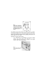
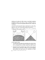
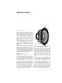
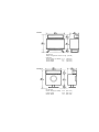
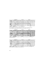
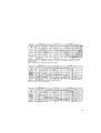
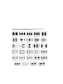
B&W
DM70
Instruction
manual
test certificate
and guarantee
DM70
B&W D M .
Trade mark of B&W electronics
Contents
Page
1.
General Description
2
2.
The Listening Room
3
3.
Installation — unpacking and connection
5
4.
Installation — Siting
10
5.
Ancillary equipment
12
6.
Specification
13
B&W electronics
Meadow Road • Worthing
England -BN11 2RX
General description
and introduction
The DM70 is a precision monitor loudspeaker for domestic and professional use, built to very high standards.
This loudspeaker, employing the combination of dynamic bass drive
unit in conjunction with an electrostatic transducer for the mid-range
and upper frequencies, is capable of most realistic reproduction of both
speech and music programme material. Because of its low distortion,
wide and balanced frequency response, and relative freedom from
colouration, it will be analytical and may well reveal shortcomings in
programme material and defects in ancillary equipment which an
inferior product w o u l d mask.
We hope that this instruction book will help you to assemble w i t h
ease, and in connecting and placing your loudspeakers, and we have
quite deliberately restricted these instructions to be simple and nontechnical wherever possible.
For an explanation of unpacking and assembling your loudspeakers
(each DM70 system, excluding stands, is packed in t w o cartons) refer
to section 3 of this booklet.
In common with all B & W loudspeaker systems, the DM70 is subjected
to stringent, quality control through every stage of manufacture and
dispatch. Individual frequency response tests are made on every DM70
during manufacture and before dispatch, and we provide you with a
calibration curve with the guarantee registration card.
Provided the instructions are followed, your loudspeaker should give
you many years of completely trouble-free service. In the event of any
query we would ask you to adopt the following procedure if service
is required:—
England, Scotland & Wales :
Contact the dealer from w h o m you purchased the loudspeakers.
All other Countries :
Contact our distributor for your country—name and address supplied
from our factory if in doubt.
B & W have appointed agents throughout the w o r l d , selected with great
care to give you the best possible service. Should you have any reason
to feel dissatisfied or if any queries arise, we will be pleased to assist
wherever possible.
The listening room
M o s t people have relatively little control over their listening room in
terms of size or shape, but as the environment in which the loudspeaker
is used plays such a big part in the quality of sound we hear, some
comments on room characteristics may be helpful before we proceed
in section 3.
There are t w o aspects of listening rooms which will most widely
influence sound reproduction : The basic dimensions of the room and
large items of furniture controlling the lower frequencies; and items of
soft furnishing together w i t h wall and other coverings affecting the
middle and upper frequencies.
All rooms have resonances, and so indeed does the concert hall, but
in the case of the latter these are so l o w in frequency, and by design,
so well spaced that they add ambience rather than colouration: The
w o r s t example in a listening room or studio would be the unlikely
event of all dimensions being the same and the room forming a cube.
The best case being a relatively large room where all dimensions are
different. Fortunately the w o r s t example is rarely, if ever, encountered
but where a choice is possible as between a square or rectangular
room the latter is to be preferred as the room resonances — k n o w n as
eigentones — occur at spaced frequencies and are therefore of lower
amplitude.
The most pronounced eigentones occur at low frequencies below
approximately 200Hz. In addition to these eigentones there is another
important influence the room has over the lower octaves of reproduced
sound. Due to the relatively small dimensions of the loudspeaker c o m pared w i t h wavelengths of sound in the lower octaves, the radiation
pattern or distribution of sound at these frequencies is effectively
spherical. When operating a loudspeaker in a room, this sphere of
sound is contained, to a greater or lesser degree, depending on position
within a series of plain surfaces formed by the walls, floor and ceiling.
This produces a factor k n o w n as 'room gain' and does in fact make
the lower frequencies considerably louder than if, for instance, the
loudspeaker were operated in the open air.
As a result of research carried out into the " r o o m g a i n " and how this
affects loudspeaker performance, the stand of the DM70 has been
specifically designed to give optimum results over a range of listening
conditions.
Before leaving the w a y in which the room affects the low frequency
part of the sound spectrum, a w o r d should be said on the construction
The ideal is a solidly built ground floor room with a concrete floor. In
rooms where there is a board and joist floor this will play a part in
both adding to bass gain and room colouration. The suspended floor
acts as a supplementary bass radiator operating at the main resonance
of the room. If your listening room has other than a solid floor and
you are troubled by excessive or resonant bass response as a result,
positioning your loudspeaker away from the corners will assist.
The subject of positioning your loudspeakers is dealt with in section
4, but before leaving the listening room we will mention its effect on
middle and high frequencies.
The soft furnishings — chairs, curtains and carpet, together with wall
and ceiling coverings are the main factors governing the performance
of a room at middle and upper frequencies. Position of cupboards,
bookshelves and other items of wall furniture also play an important
role in these parts of the spectrum.
A room with insufficient soft furnishing will give a hard or steely tonal
quality to middle and upper frequencies, with strings suffering especially. A room w i t h too many soft furnishings — an over-damped room —
will sound dull and lifeless, a somewhat similar effect to putting 'top
cut' on your amplifier tone control.
The ideal mid/high frequency reverberation times ( a measure of
acoustic 'brilliance' or 'dullness') are somewhat subjective, but
generally a good balance can be obtained by opposing a reflective
surface with an absorbent one. As an example ceilings are usually
bare and reflective and this can be well balanced by a fitted carpet. An
unbroken wall facing large w i n d o w areas can be broken by a bookcase
on the opposite wall.
When furnishing a new room which is to be used for listening to
reproduced music, it is usually wise initially to underdamp the room
and then add absorbent articles after the correct balance has been
determined.
Installation unpacking and connection
For safety in transport t h e D M 7 0 Improved system is packaged in
three cartons, f o r each loudspeaker:—
Carton 1
Main cabinet with fitted power supply unit.
Carton 2
T w o metal stands for the pair of loudspeakers.
Carton 3
The " 7 0 2 " electrostatic unit complete.
WARNING
IT IS ESSENTIAL THAT THE ASSEMBLY A N D INSTALLATION
INSTRUCTIONS BE CAREFULLY READ BEFORE CONNECTING
THIS SYSTEM TO THE MAINS OR AUDIO SUPPLY.
Unpacking.
Unpack the largest cartons and remove the accessory
bag tied to the rear of the power pack at the back of each cabinet.
This bag contains all necessary hardware and spares, such as fuses.
The smaller packages should then be unpacked. It is a worthwhile precaution to save the polystyrene pieces in which the electrostatic units
are packed in case of any future transportation.
The stands may n o w be fitted to the base of the cabinets by means
of the metal bolts provided which will mate w i t h sealed captive nuts
inside the base of the cabinet.
Mains.
Before attempting to connect the mains supply to your DM70
check that your supply voltage agrees with the adjustment made to
the system before it left our factory.
Fig. 1
Rear view of Continental
power supply, showing label
indicating the power supply
voltage. The power supply for
the Standard version is similar
but rotated through 90
degrees.
The regulation of the power supply is such that, normally, no adjustment will be necessary and the unit is set for the country of destination,
e.g. European or America, etc. If, after having made this check on mains
supply, it is necessary to adjust the mains voltage, please refer to the
above diagram and read the instructions regarding the removal of the
power supply from the cabinet.
Adjustment of mains voltage setting.
IT IS IMPORTANT TO DISCONNECT THE M A I N S POWER
SUPPLY A N D AUDIO FEED FROM AMPLIFIER (IF CONNECTED) BEFORE ATTEMPTING TO REMOVE THE POWER
SUPPLY UNIT FROM THE CABINET.
Fig. 2
Shows a 70C power supply
unit removed from the
cabinet.
.
To remove the power supply unit from the cabinet, unscrew the four
screws at the side of the rear panel of the unit and withdraw it, unplugging the audio output to the bass unit. (If the 701 electrostatic
unit has already been fitted to the cabinet, it will be necessary first to
remove this, by reversing the assembling instructions which follow.)
The various adjustments to the mains voltage selector are selfexplanatory. Re-insert the power supply unit into the cabinet, securing
by means of the four screws.
Final Assembly. Having made the checks, and adjustments, if
necessary, the 701 electrostatic unit may now be fitted. W i t h the
cabinet secured to its stand, the electrostatic may now be inserted
into the sockets on the top of the cabinet. Spigots on both feet of
the 701 locate in corresponding sockets and they can only be assembled in the correct manner. Having inserted the electrostatic unit,
make it secure by screwing down to the cabinet through the hole in
the rear of each 701 foot with the screws provided.
Connection. UNDER NO CIRCUMSTANCES SHOULD THE 701
ELECTROSTATIC UNIT BE REMOVED WITH EITHER THE M A I N S
SUPPLY OR THE AUDIO FEED FROM THE AMPLIFIER CONNECTED.
W i t h the system completely assembled, connection may now be made
to the necessary alternating current power supply — the power drain
is negligible. Connection to the mains is made by the three-core cable
provided, the standard colour-coding of which i s : —
YELLOW/GREEN
—
EARTH
BROWN
—
LIVE
BLUE
—
NEUTRAL
FOR COMPLETE SAFETY, IT IS IMPORTANT TO USE A THREE PIN
SUPPLY MAKING A SOUND EARTH CONNECTION.
The output from your amplifier should, of course, be connected to the
AUDIO INPUT of the loudspeaker — located on the back panel of the
power supply unit Connection is made to the terminal sockets, either
by connecting bared wires to the binding posts, or by using standard
4mm. "banana" plugs, or similar. The terminals are colour-coded red
and black and these are connected to the positive and negative loudspeaker outputs respecrtively.
of
your
amplifier.
It is advisable to keep the series resistance of connecting cables as
low as possible by using reasonably heavy gauge cables. Our recommendations are.—
Loudspeakers under 10 metres away from amplifier: use 16/0.2mm.
Loudspeakers over 10 metres away from amplifier: use 24/0.2mm.
Phasing. The centre image and correct spread in stereophonic reproduction relies on "in phase" components of sound of equal amplitude, and it is essential to check that your loudspeaker and other
items in the "reproducing chain" are correctly connected. If other
items in the chain, such as pick-up cartridge, etc., are correctly connected, then the method of connection of the loudspeakers as outlined
above will be correct. However, there is a simple test worth making:—
Feed both channels of your system with a monophonic source, e.g.
mono radio, a mono record, or a stereophonic source with the function
selector of the control unit of your amplifier switched to "A + B",
"Left + Right", or " M O N O . " If phasing is correct, then, when listening from a central position between the loudspeakers, the sound should
appear to emanate from a relatively small area between the loudspeakers. If the phasing is incorrect, the image will be broader and spread
across the area between the loudspeakers. (Commercial gramophone
records are available which illustrate this " p h a s i n g " procedure, should
there remain any difficulty or doubt.)
If phasing of any item is incorrect, reversal of any one item will correct
the fault.
Operation. At the rear of the 701 electrostatic unit will be found a
removable absorbent pad, the function of which is to reduce rear
radiation in locations where the loudspeaker is placed close to a wall
or corner. This pad provides a useful method of varying the distribution
pattern of the electrostatic unit above 500Hz. to suit both ambient
conditions and the user's personal preference in terms of the ratio of
direct to reflected sound. This absorbent pad can be readily withdrawn
with the fingers from its recess in the rear of the electrostatic mount.
With the rear pad withdrawn, greater ambience will be experienced—
depending on the reflective nature of the wall and furnishings behind
the loudspeaker — there will be a slight increase in sound level above
500Hz. with the electrostatic unit operating in this condition. If it is
8
J
I
desired to operate the DM70 at very high sound levels, or where high
powered continuous sine wave inputs are applied, the rear absorbent
pad should be placed in position.
It will be observed that on the rear panel of the Power Unit there is
a neon indicator. This shows that the mains supply is functioning. If
the neon does not light when the mains is connected, the fuse should
be checked. A spare fuse is provided — but repeated replacements
should not be made — and if this fails you should consult your dealer.
The continental DM70 is protected on input with fuses, accessible on
the rear panel of the power supply (see figure 1 page 6 ) . The correct
values are 1.5 amp for the fuse marked Treble, and 2 amp for the
fuse marked Bass.
Although in the case of the DM70 (due to its remarkable dispersion
characteristic) positioning is not as critical as w i t h many conventional
loudspeaker systems, this system is quite a substantial piece of
furniture in its o w n right, and it is worthwhile taking care in siting the
loudspeakers in the most acceptable positions, both visually and
acoustically.
It will be found that the stereo image is preserved over a wide listening angle, and the satisfactory listening area larger in the case of the
DM70 than with most conventionally designed loudspeakers.
Example of sitings of a pair of DM70's and a pair of conventional
Loudspeakers are illustrated in figure 3.
Fig. 3 Listening area shown hatched in.
A simple guide to siting.
1.
It is suggested that in initial layout a flexible lead is used, and the
positions of the loudspeakers experimented with on familiar music
until a natural balance is obtained. Permanent installation may
then be undertaken after the exact positions have been decided.
2.
Bass response within the bottom t w o octaves will vary w i t h the
positions of the loudspeakers relative to any plane surfaces.
Minimum bass will occur in the unlikely event of the loudspeakers
being situated near the centre of a room. Conversely, maximum
bass response will result should the loudspeakers be tightly
" c o u p l e d " to the corners of the room.
10
3.
Due to the wide and balanced horizontal dispersion of the DM70,
their horizontal position will not be critical. We would normally
suggest that in domestic rooms of normal size they be not closer
than eight feet (2.5 metres) apart, or separated by more than
fifteen feet (4.5 metres) to give an even and solid stereo image.
4.
The final point for consideration is whether to place the loudspeakers parallel with the wall or surface or to angle them towards
the listening area. The governing factors are the distance between
the loudspeakers and the distance of the listeners from them.
Considerable latitude is offered in the case of the DM70, but, as a
general rule, the angle by which they should be turned is increased
the further they are apart and the closer you are seated to them.
Ancillary equipment
Because of its exceptionally good frequency linearity and relative
freedom from colouration and distortion, the DM70 is capable of extremely faithful reproduction, provided that the signal fed to it is of
the very highest quality. A monitor loudspeaker — and the DM70 is
such a high-quality system — is therefore analytical and will reveal
faults in ancillary equipment and programme material which could well
be masked by an inferior loudspeaker.
It is not appropriate in this instruction book to recommend specific
items of ancillary equipment and fortunately there is a wide range of
top quality equipment available. In general terms, however, it is wise
to match the quality of the various items in the reproducing chain. A
good guide being to spend approximately equal amounts on the pickup arm and motor combination; on the amplifier or tuner/amplifier; and
on the loudspeakers.
The power rating required of the amplifier will depend on the size of
your listening room, on the preferred listening level, as well as on the
sensitivity of the loudspeakers. True RMS outputs of between 25 and
100 watts per channel will meet all requirements.
Volume and Tone control Settings. The correct operation of these
controls is important if realistic reproduction is to be obtained. Dealing firstly with volume control setting: it is important to set the volume
control of your amplifier at such a level as to recreate the original
level of sound that would be heard in the concert hall or place of
original live performance.
For many reasons it may not always be possible to listen at original
sound levels. For this and other reasons, tone controls are provided.
The actual tone control settings will depend on a number of factors
too numerous to detail. As a general guide, orchestral music will
require some bass lift and little, if any, treble control when played
below natural level, speech will require bass cut and slight treble cut
when played above natural level. Between these t w o extremes there
are many settings which will be quickly determined by listening.
12
Specification
General Description
B. & W. D M 7 0 is a h y b r i d design employing
exclusive Model 701 11-element wide dispersion doublet electrostatic unit (patent
no. 1239658), DW 13/70 high power low
distortion moving coil bass unit w i t h complex crossover and filter unit and dividing
network. Relative sensitivities between the
dynamic and electrostatic units are accurately equalised by a massive auto transformer.
The vitally important middle and upper frequencies are handled w i t h o u t the attendant
phase distortion associated w i t h crossovers
in this region and the exceptionally wide
dispersion of these frequencies give a much
greater degree of stability of the stereo
image.
Alternative Cabinet stylings are available but
both offer an extremely rigid critically
damped infinite enclosure w i t h low system
resonance. The bass driver is a no compromise unit capable of handling high power
w i t h extremely low distortion and employs
a specially braced cone assembly w i t h damping pads at critical damping points and the
exclusive B. & W. triple suspension.
Detailed Specification
Drive Units
DW13/70. This low frequency unit, of nominal piston diameter twelve inches (305 mm)
is of size consistent w i t h the enclosure
volume and method of acoustic loading used.
The resulting system resonance is 40 Hz.,
the unit itself having a free air resonance of
approximately 28 Hz.
The cone is formed f r o m long fibre paper
material, w i t h mass adjustment and damping
(to discourage cone break-up) provided by
critically positioned rectangular section of
synthetic rubber attached to the cone face.
The massive ceramic magnet assembly, in
conjunction w i t h the low impedance of the
voice coil, ensures high damping leading to
excellent transient-handling capacity.
DW 13/70 Bass Unit
Electrostatic mid-and high-frequency unit.
The 701 electrostatic module (patent number 1239658) covers all audio frequencies
above 500 Hz. 3y virtue of the relatively
small vertical dimension of the u n i t , the
vertical distribution is excellent in the m i d frequency region and the curved geometry
of the eleven integrated modules in each
701 provides very wide and u n i f o r m frontal
radiation of sound, w i t h a strong rear
radiation pattern which can be controlled to
suit ambient conditions or personal judgement.
In terms of distortion, new standards are
set and reference to the figures, in the
f o l l o w i n g pages, showing harmonic content
w i l l demonstrate the extremely low levels
of the commonly troublesome odd harmonics at high sound power o u t p u t .
The power handling of this mid-high frequency unit confirms research findings that
it is w i t h i n the mid-frequency band (say
500 Hz. to 5 kHz) that m a x i m u m power is
applied. The concept of the 701 electrostatic u n i t provides coverage of all audio
frequencies above 500 Hz. reducing intermodulation distortion and Doppler effect.
13
Electrostatic
Unit model
A prime design point of the 701 is that it is
free-standing. This makes it possible easily
to remove the unit in the event of damage
etc., and service being required, thus avoiding the transportation of entire heavy and
bulky system.
Crossover and Filter Unit
The 500 Hz. crossover frequency between
the DW13/5 bass unit and the 701 electrostatic unit ensures that both these transducer
elements operate over their o p t i m u m frequency ranges. Care has been taken in the
design of the low-pass section of the filter
to ensure that maximum amplifier damping
may be transferred to the bass unit by the
use of heavy gauge copper in the series inductor, over a ferrite core. In addition, an
impedance- and level-controlling transformer
forms a part of the bass unit filter.
The power supply and high-pass filter for
the 701 electrostatic unit is solidly and
safely housed in a steel case. The mains lead
is captive, for safety.
Cabinet
The cabinet is constructed of 25mm chipboard; in the case of the " C o n t i n e n t a l "
version, the curved f r o n t formed f r o m 19mm
p l y w o o d . The grille materials (earthed metal,
f r o n t and rear for the electrostatic) have
been chosen to give minimal deterioration
of the acoustic performance.
14
701
The " S t a n d a r d " version of the cabinet is
available in teak or walnut veneers and a
choice of walnut veneer or satin white finish
for the "Continentals."
Acoustic Loading
The acoustic loading for the bass drive unit
is of the " i n f i n i t e b a f f l e " t y p e , synthetic
damping material being used to achieve
o p t i m u m system " Q " . A resonance-controlling removable pad is fitted to the rear of
the electrostatic.
Sensitivity
17 watts into nominal impedance required
to produce a sound level of 95 dB. at one
metre at 400 Hz
Power Handling
The D M 7 0 is suitable for high quality amplifiers w i t h true RMS outputs of between
25 and 100 watts, w i t h double fuse protection on C and CA versions.
STANDARD
Dimensions.
Weight: Weight w i t h stand: 4 5 . 4 k g . (100 lbs)
Standard
Overall Height (on Stand)
Overall Width
Overall Depth
31 i "
32"
15"
Continental
Overall Height (on Stand)
Overall Width
Overall Depth
32 s" (820 mm)
26 s" (680 mm)
1 5 1 " (390 mm)
(808 mm)
(815 mm)
(382 mm)
CONTINENTAL
Frequency Response. On-Axis ± 5 dB. 60 Hz. to 15kHz.
On axis response of a production sample DM70 taken in Ft & D Anechoic Chamber.
B & K equipment used throughout, w i t h type 4133 microphone at 1 metre.
Crossover and Filter Unit. Individual Acoustic o u t p u t f r o m each Drive U n i t , showing
Crossover frequency.
Polar Distribution. + 3 dB envelope to on-axis f r o m 20 Hz to 20 kHz over 60 degree arc.
DM70 response for 30 degree arc and 60 degree arcs.
16
Impedance. Nominal impedance 8 ohms. Not greater than 30 ohms or less than 4 ohms
20 Hz to 9 k.Hz., the impedance m i n i m u m occurring in a frequency region of very low
music energy.
Plot of impedance of production sample of DM70.
Distortion. Harmonic analysis plotted against frequency
Content of 2nd. and 4th. Harmonics.
Content of 3rd. and 5 t h : Harmonics.
17
Transient Response. Tone Burst oscillograms taken at one-third octave intervals in ou
Research Anechoic Chamber. Microphone type B & K 4133.
31.5 Hz
40 Hz
50 Hz
63 Hz
80 Hz
100 Hz
125 Hz
160 Hz
200 Hz
250 Hz
315 Hz
400 Hz
500 Hz
630 Hz
800 Hz
1kHz
1.25 kHz
1.6 kHz
2.0 kHz
2.5 kHz
3.15 kHz
4 kHz
5 kHz
6.3 kHz
8 kHz
10 kHz
18
12.5 kHz
16 kHz
20 kHz
Polar response
100 Hz
Polar response
1 k.Hz.
Polar response
Polar response
10 k.Hz.
RkH?
19