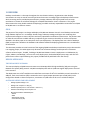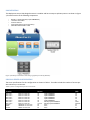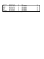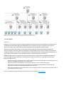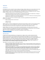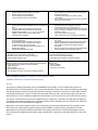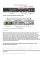
1
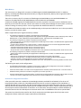
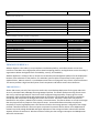
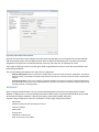
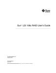
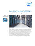
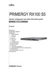
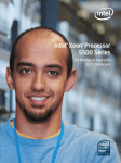
White Paper
50,000-Seat VMware View Deployment
Jack McLeod, Chris Gebhardt, Brian Collins, and Rachel Zhu, NetApp; Mac Binesh and Fred Schimscheimer,
VMware; and Arthur Perkins, Fujitsu America
October 2010 | WP-7108
If you are a medium to large Enterprise that uses 30 or more personal computers in house, the implementation of a
VMware View deployment like the one described in this white paper could save you IT dollars and man hours by
simplifying data and computer hardware management. It can also help keep your users working on the business at
hand instead of installing and administering software on their personal computers.
TABLE OF CONTENTS
Contents
1 OVERVIEW ...................................................................................................................... 3
GOAL .................................................................................................................................................................. 3
DESIGN APPROACH ............................................................................................................................................. 3
2 PARTNERS ....................................................................................................................... 6
NETAPP............................................................................................................................................................... 6
VMWARE ............................................................................................................................................................ 7
FUJITSU............................................................................................................................................................... 8
3 INFRASTRUCTURE COMPONENTS .................................................................................. 8
NETAPP KILO-CLIENT ........................................................................................................................................... 8
ACTIVE DIRECTORY ............................................................................................................................................. 9
NETWORK ......................................................................................................................................................... 10
SERVERS............................................................................................................................................................ 11
STORAGE .......................................................................................................................................................... 17
VMWARE VSPHERE 4.1 ..................................................................................................................................... 18
VMWARE VIEW 4.5 ........................................................................................................................................... 20
WINDOWS 7 ..................................................................................................................................................... 21
4 CONCLUSION ................................................................................................................ 24
5 REFERENCES.................................................................................................................. 24
6 ACKNOWLEDGEMENTS................................................................................................. 24
1 OVERVIEW
Desktop virtualization is a hot topic throughout the virtualization industry. Organizations view desktop
virtualization as a way to control costs and use limited resources to manage large-scale desktop infrastructures
while increasing security and deployment efficiency. NetApp, VMware, and Fujitsu joined forces as major
contributors to create an architectural design for a 50,000-seat VMware® View™ architecture. This project
demonstrates the most reliable methods for deploying a scalable and easily expandable environment from 5,000
to 50,000 seats in an efficient manner.
GOAL
The purpose of this project is to design and deploy a 50,000-seat VMware View 4.5 virtual desktop environment
using VMware vSphere™ 4.1 on NetApp® shared storage. VMware, NetApp, and Fujitsu are combining their
respective technologies to create a dynamic and easily expandable virtualization infrastructure. The partners want
to make this environment scalable and easy to replicate to give customers the ability to use the architecture
detailed in this white paper as an example for their own deployments. This deployment uses a Pool of Desktops
(POD) concept that is based on the hardware and software needed for deploying 5,000 seats into a virtualization
infrastructure.
This document provides an initial overview of the ongoing 50,000-seat desktop virtualization project. Because this
is an ongoing project, this white paper only discusses the architectural design and the partner involvement.
A future technical report, TR-3865, “Building a 50,000-Seat VMware View 4.5 Deployment: A Collaboration by
Fujitsu, VMware, and NetApp,” will cover the entire deployment, the detailed deployment steps, and all of the
performance metrics captured during this project (TR-3865 will be published in the near future).
DESIGN APPROACH
THE DEPLOYMENT SCENARIO
This scenario deploys a 50,000-seat environment on 10 NetApp FAS3170 high-availability (HA) pairs using the
Network File System (NFS) protocol. A 20,000-seat deployment and six 5,000-seat regular deployments are used
in this scenario.
The deployment uses a 50% read/write mix and allows a minimum of 10% CPU availability on each controller. In
addition, each virtual machine (VM) is assumed to use 12 input/output operations per second (IOPS) in the
configuration. Based on these assumptions, a maximum of 5,000 seats can be run on a FAS3170 HA pair.
SOFTWARE NEEDED FOR DEPLOYMENT
•
NetApp System Manager 1.01
•
NetApp VSC 2.0 (RCU 3.1 Plug-in)
•
VMware vSphere (ESX 4.1 and vCenter™ Server 4.1)
•
VMware View Manager and Composer 4.5
•
Microsoft® Windows® 2008 Enterprise
− DHCP
− DNS
− DHCP Relay Agents
− Active Directory® (AD)
POD DEFINITION
This deployment uses a POD design because it is modular and has an easy-to-replicate process. As shown in Figure
1, the POD consists of the following components:
•
•
•
•
•
60 ESX 4.1 Hosts (Primarily Fujitsu PRIMERGY)
1 FAS3170 HA Cluster
2 vCenter Servers
3 Connection Servers (running PCoIP®)
5,000 Microsoft Windows 7 VMs
Figure 1) Desktop virtualization POD design (graphic provided by VMware).
PHYSICAL SERVER CONFIGURATION
The server specifications for this configuration are shown in Table 1. The table includes the number of servers per
Active Directory environment.
Table 1) Server configuration per AD environment.
vCenter
Location
AD Domain
#
Manufacturer
Servers
RAM
(GB)
New York 1
New York 2
New York 3
New York 4
New York 5
New York 6
New York 7
New York 8
Chicago
Dallas
Phoenix
EAST.us.cvnfw.com
EAST.us.cvnfw.com
EAST.us.cvnfw.com
EAST.us.cvnfw.com
EAST.us.cvnfw.com
EAST.us.cvnfw.com
EAST.us.cvnfw.com
EAST.us.cvnfw.com
CENTRAL.us.cvnfw.com
CENTRAL.us.cvnfw.com
WEST.us.cvnfw.com
30
30
30
30
30
30
30
7/15/16
50
52
46
48
48
48
48
48
48
48/48
48/24/48
24
24
24
Fujitsu PRIMERGY
Fujitsu PRIMERGY
Fujitsu PRIMERGY
Fujitsu PRIMERGY
Fujitsu PRIMERGY
Fujitsu PRIMERGY
Primarily Fujitsu PRIMERGY
Primarily Fujitsu PRIMERGY
Cisco
Cisco
Cisco
San Francisco
Tokyo
Singapore
Sydney
Auckland
London
Munich
Dubai
Johannesburg
WEST.us.cvnfw.com
APAC.apac.cvnfw.com
APAC.apac.cvnfw.com
ANZ.apac.cvnfw.com
ANZ.apac.cvnfw.com
EU.emea.cvnfw.com
EU.emea.cvnfw.com
AME.emea.cvnfw.com
AME.emea.cvnfw.com
54
30
30
30
30
30
30
30
30
Cisco
Fujitsu PRIMERGY
Fujitsu PRIMERGY
Fujitsu PRIMERGY
Fujitsu PRIMERGY
Fujitsu PRIMERGY
Fujitsu PRIMERGY
Fujitsu PRIMERGY
Fujitsu PRIMERGY
The AD specifications for this configuration are also shown in Figure 2.
24
48
48
48
48
48
48
48
48
Figure 2) Active Directory overview (graphic provided by VMware)
2 PARTNERS
NETAPP
NetApp creates innovative storage and data management solutions that deliver outstanding cost efficiency and
accelerate business breakthroughs. Our dedication to the principles of simplicity, innovation, and customer
success has made us one of the fastest-growing storage and data management providers today.
Customers around the world choose us for our “go beyond” approach and broad portfolio of solutions for
server-to-storage virtualization, business applications, data protection, and more. Our solutions and virtualized
storage technologies can provide nonstop availability of critical business data and speed product development, so
you can deploy new capabilities with confidence and get to revenue faster than ever before.
NetApp storage solutions for VMware virtual desktop environments simplify data management and save time
while leveraging existing investments in heterogeneous storage arrays across FC, iSCSI, NFS, and CIFS. With
NetApp storage you can:
•
Reduce virtual desktop storage use by 50% or more by deduplicating redundant data stored across virtual desktops, user
directories, and backup and disaster recovery (DR) copies.
•
Provision thousands of virtual desktops in minutes with nearly instant, low-overhead storage cloning.
•
Provide users continuous access to their virtual desktops with 99.999% storage availability, automated DR, and
performance acceleration that addresses desktop boot or log-in storms.
•
Back up all virtual desktops and user data directly on the storage system while cost effectively keeping a daily history of
every desktop for months or years.
Discover our passion for helping companies around the world go further, faster at www.netapp.com.
VMWARE
VSPHERE 4.1
Leveraging more than a decade of industry-leading technology, VMware vSphere sets a new standard as the most
robust and reliable virtualization platform that forms a good foundation for building cloud infrastructures.
VMware vSphere is used in over 170,000 deployments in companies of all sizes throughout the world. The latest
release of VMware vSphere (version 4.1) pushes the platform even further by:
•
Dramatically expanding the scale of the platform to an unmatched number of VMs and virtualized hosts, enabling the
creation of private and public clouds at even lower operational costs than before
•
Introducing new capabilities for the most efficient aggregation of IT resources into an elastic pool of computing power that
applications can consume on demand as a utility-like service
The new and enhanced features that VMware vSphere 4.1 delivers, grouped by the major benefits of the
platform, are as follows:
•
Efficiency through utilization and automation
•
Agility with control
•
Freedom of choice
VMware vSphere virtualizes and aggregates the underlying physical hardware resources across multiple systems
and provides pools of virtual resources to the data center. It transforms data centers into simplified cloud
computing infrastructures and enables IT organizations to deliver flexible and reliable IT services.
VMware vSphere is the industry’s most complete virtualization platform, with infrastructure services that
transform IT hardware into a high-performance shared computing platform, and application services that help IT
organizations deliver the highest levels of availability, security, and scalability.
Note: For a complete and detailed list of new features and capabilities in VMware vSphere 4.1, visit
www.vmware.com/go/vshpere.
VMWARE VIEW
Purpose-built for delivering desktops as a managed service, VMware View™ provides a positive end-user
experience and transforms IT by simplifying and automating desktop management. Centrally maintaining
desktops, applications, and data reduces costs, improves security, and, at the same time, increases availability and
flexibility for end users. Unlike other desktop virtualization products, VMware View is a tightly integrated
end-to-end solution built on the industry-leading virtualization platform. VMware View allows customers to
extend powerful business continuity and disaster recovery features to their desktops and standardize on a
common platform from the desktop through the data center to the cloud.
The VMware View solution provides a wide range of benefits.
•
Simplify and automate desktop management. VMware View lets you manage all desktops centrally in the data center
and provision desktops instantly to new users, departments, or offices. Create instant clones from a standard image and
create dynamic pools or groups of desktops.
•
Optimize end-user experience. The VMware View PCoIP display protocol provides a superior end-user experience
over any network. Adaptive technology provides an optimized virtual desktop delivery on both the LAN and the WAN.
Address the broadest list of use cases and deployment options with a single protocol. Access personalized virtual
desktops complete with applications and end-user data and settings anywhere and anytime with VMware View.
•
Lower costs. VMware View reduces the overall costs of desktop computing by up to 50% by centralizing management,
administration, and resources and by removing IT infrastructure from remote offices.
•
Enhance security. Because all data is maintained within the corporate firewall, VMware View minimizes risk and data
loss. Built-in Secure Socket Layer (SSL) encryption provides secure tunneling to virtual desktops from unmanaged
devices or untrusted networks.
•
Increase business agility and user flexibility. VMware View accommodates changing business needs, such as adding
new desktop users or groups of users, while providing a consistent experience to every user from any network point.
•
Provide built-in business continuity and disaster recovery. VMware View is built on industry-leading VMware
vSphere, allowing you to easily extend features such as HA and Fault Tolerance to your desktops without having to
purchase expensive clustering solutions. Automate desktop backup and recovery as a business process in the data
center.
•
Standardize on a common platform. VMware View includes VMware vSphere and brings all the benefits and enterprise
features of the data center to the desktop. Extending features such as VMotion™, HA, Distributed Resources Scheduler,
and Fault Tolerance to your desktops provides a built-in disaster recovery and business continuity solution. Optimized
specifically for desktop workloads, VMware vSphere is able to handle the high loads associated with desktop operations
such as boot-up and suspend operations. Standardize your virtualization platform, and use a single solution to manage
both servers and desktops from the data center through to the cloud.
VMware View provides unified access to virtual desktops and applications that run in a central secure data center
and are accessible from a wide variety of devices. VMware View Composer streamlines image management while
reducing storage needs through the use of VMware Linked Clone technology.
FUJITSU
Fujitsu is a leading provider of information and communication technologies (ICT)-based business solutions for the
global marketplace. With approximately 170,000 employees supporting customers in 70 countries, Fujitsu
combines a worldwide corps of systems and services experts with highly reliable computing and communications
products and advanced microelectronics to deliver added value to customers. Headquartered in Tokyo, Fujitsu
Limited (TSE:6702) reported consolidated revenues of 4.6 trillion yen (US$50 billion) for the fiscal year ending on
March 31, 2010. For more information, refer to www.fujitsu.com.
Fujitsu America Inc. is a leading ICT solutions provider for organizations in the United States, Canada, and the
Caribbean. Fujitsu enables clients to meet their business objectives through integrated offerings including
consulting, systems integration, managed services, outsourcing, and for enterprise applications, data center, and
field services operations, based on server, software, storage, and mobile technologies. Fujitsu provides
industry-oriented solutions for the manufacturing, retail, healthcare, government, education, financial services,
and communications sectors. For more information, refer to http://solutions.us.fujitsu.com/.
3 INFRASTRUCTURE COMPONENTS
NETAPP KILO-CLIENT
The NetApp Kilo-Client is a test environment that allows NetApp to quickly configure and boot a large number of
physical and/or virtual clients to run tests against NetApp storage hardware and software. The deployment is
performed on the third generation (or Kilo 3G) of this environment, which takes advantage of Fujitsu PRIMERGY
RX200 S5 rackable servers.
The real key to the Kilo-Client is its ability to perform fast, flexible, and space-efficient booting. As in any cloud
infrastructure, the Kilo-Client has the capability to quickly repurpose any number of clients for any task—physical
or virtual. The Kilo-Client uses a combination of Fibre Channel (FC) and Fibre Channel over Ethernet (FCoE) boot to
boot each physical server and an NFS boot to support VMs booting on servers configured to run virtualization. The
FC boot in combination with our dynamic logical unit number (LUN) cloning capability is used to rapidly and
efficiently boot physical and virtual servers.
The Kilo-Client maintains a set of "golden" boot images (as FC LUNs) for each operating system and application
stack. Through the use of NetApp SnapMirror® and NetApp FlexClone®, hundreds of clones can quickly be
reproduced for each physical server being configured for a test. This approach allows near-instantaneous image
provisioning with a near-zero footprint.
The process of booting VMs builds on the same steps:
1.
2.
3.
4.
5.
6.
Boot VMware ESX on each host for the test.
Register those hosts dynamically in the VMware vCenter.
Prepare the correct network settings and datastores for the VMs.
Use VSC 2.0 to clone and register the appropriate number and types of VMs.
Dynamically register the servers in DNS and DHCP, and boot the VMs.
Check to make sure that everything is correct.
COMPLETE AUTOMATION
Over the past several years, Perl scripts have been created that work in conjunction with NetApp and VMware
tools to automate the steps to boot VMs so that 500 to 1,000 VMs can be routinely deployed in 2 to 3 hours.
PHYSICAL LAYOUT
The design concentrates all boot infrastructures in one location. Servers and storage systems are grouped into
pods that include just the necessary switching (IP and FC) to meet the needs of the pod. This makes the pods easy
to replicate. In addition, it is easy to grow and scale the Kilo-Client in any dimension by adding another pod of that
type. Manual setup and teardown are no longer required. Therefore, new pods can be deployed anywhere in the
data center as more space is needed, allowing the data center to operate with maximum efficiency.
ACTIVE DIRECTORY
Figure 3) Active Directory.
DOMAIN STRUCTURE
This design uses the following business criteria:
•
All user accounts must be in the root domain.
•
Application servers must reside in as few domains as possible for simplified administration, reduced security exposure,
and manageability.
•
Regional administrators must have full and autonomous control over the administration of the machines, security, and
policies in their sphere of responsibility.
This leads to a three-tier design containing a single forest root domain to contain the user accounts,
enterprise-wide Group Policy Objects (GPOs), and the virtual desktop users’ security group.
The application servers are contained in three geographically oriented sub-domains. Each geographic sub-domain
contains two or three regional domains at the third and bottom tier.
TOP LEVEL
The top-level domain contains four Windows Server 2008R2 servers providing the Directory Service and DNS
roles. All user accounts are contained in this domain. The exceptions are the domain and local administrator
accounts in the sub-domains, and the service accounts as needed at the second-level (application server) and
third-level (regional) domains.
Two GPOs are created as follows:
•
Virtual Desktops. The Virtual Desktops GPO is created to contain the various VM settings by using the template
provided from VMware, which is a recommended best practice by VMware.
•
Virtual Desktop Users. The Virtual Desktop Users GPO is created to contain the virtual desktop user settings by using
the template provided from VMware, which is a recommended best practice by VMware.
All user accounts that use the virtual desktop machines are placed in an Organizational Unit (OU) named Virtual
Desktop Users. This OU contains a security group for the virtual desktop users as well as a link to the Virtual
Desktop Users GPO.
GEOGRAPHICAL TIER
These domains are largely vacant because the focus of this exercise is the virtual desktops at the bottom tier
exclusive of any enterprise application servers. Each of the three geographical layer domains contains two
Windows Server 2008R2 servers providing Directory Service and DNS roles.
REGIONAL TIER
At the lowest level of the forest, the regional tier, each domain contains three Windows Server 2008R2 servers.
Two servers contain the Directory Service and DNS roles. The third server provides the DHCP service for the
region.
Each domain contains an OU named Virtual Desktops. All of the deployed virtual desktops are placed in this OU. A
link is created to the Virtual Desktop Machines GPO contained in the root domain.
NETWORK
This deployment uses a network design with Cisco® Nexus 7000 switches and Cisco Nexus 5020 switches. All of
Cisco’s best practices are followed in the setup of the Nexus environment. For more information on configuring a
Cisco Nexus environment, visit www.cisco.com.
The goal in using a Cisco Nexus environment for networking is to integrate its capabilities to logically separate
public IP traffic from storage IP traffic. By doing this, the chance of issues developing from changes made to a
portion of the network is mitigated.
This configuration uses Cisco Nexus 5020 switches, which support vPCs. Therefore, a logical separation of the
storage network from the rest of the network is achieved while providing a high level of redundancy, fault
tolerance, and security. The vPC also provides multipathing, which allows you to create redundancy by enabling
multiple parallel paths between nodes and load balancing traffic where alternate paths exist.
SERVERS
FUJITSU
The major portion of this deployment uses 468 Fujitsu® PRIMERGY RX200 S5s. Each of these Fujitsu PRIMERGY
RX200 S5 is configured with 48GB of RAM and two 2.26 GHZ Intel® Xeon® Nehalem E5520 processors. The
processors are all quad-core, 8-threaded processors delivering a total of 8 cores and 16 threads per system.
Introduction and Highlights of the S5 Generation PRIMERGY Dual-Socket Rack Servers
The PRIMERGY RX200 S5, offered in a flat rack housing of only one height unit (1U), provides a significantly
improved performance, higher extendibility, greater reliability, and decreased power consumption compared with
previous generation servers. This means that it can offer more for less—by delivering increased processing power
and consuming less power compared with the older systems. A key part of this energy efficiency is our innovative
PRIMERGY Cool-safe™ system design of the new dual S5 rack server generation. PRIMERGY Cool-safe™ is a design
methodology that improves system cooling, decreases power consumption, and improves the reliability of
PRIMERGY servers through the optimization of power subsystems, airflow, fan design, chassis design, and power
management features. In the PRIMERGY RX200 S5, the efficiency of the hot-pluggable, redundant power supply
units has been increased to 89% to improve energy use. Depending on the load, sensor-controlled, hot-pluggable,
and redundant fans are used to maintain an optimal temperature in the server at all times. These fans are
supported by an innovative, extremely air-permeable front panel with a honeycomb design and barrier-free,
internal airflow channels inside the server.
The integrated ServerView Power Management enables the monitoring and active planning of maximum
consumption loads, thus enabling cost efficiency. The result is a high-performance server, increased reliability for
major components, and reduced data center cooling requirements.
The careful design of this server and the strict adherence to performance and reliability resulted in the RX200 S5
achieving a first-place score in VMware’s VMmark Benchmark for dual-socket systems. On August 11, 2009,
Fujitsu achieved a VMmark score of 24.20@17 tiles with a PRIMERGY RX200 S5 and VMware ESX 4.0. This score as
well as the detailed results and configuration data can be seen at
http://www.vmware.com/products/vmmark/results.html. With a score of 24.20@17 tiles, the PRIMERGY RX200
S5 was (at the time the benchmark result was published) the highest scoring 1U rack server with 8 processing
cores and was rated third in the VMmark ranking for servers in the 8-core.
PRIMERGY servers with Cool-safe™ allow you to get the most performance out of today’s multicore processor
designs by providing a well-cooled, energy efficient, reliable, and expandable platform for server deployments and
for virtualization.
TECHNICAL HIGHLIGHTS
The common design principles present across the S5 generation of PRIMERGY Dual-Socket servers are:
•
Increased power efficiency due to the energy-efficient Cool-safe™ design, EPA-compliant PSU ( ≥ 89% energy
efficiency), cable-free design of the motherboard wherever possible, and new power management features such as
Power Consumption Limiting and Budgeting
•
Dual-Core, Quad-Core, or Turbo Quad-Core Intel Xeon processor 5500 series with up to a maximum of 1333 MHz bus
speed for DDR3 RAM and 8MB of shared TLC. These processors support the new serial QuickPath Interconnect (QPI)
links and offer outstanding performance and a balanced architecture that incorporates next-generation memory and I/O
technologies
•
On-board dual Gb Ethernet controller with TCP/IP acceleration and iSCSI support
•
Integrated Remote Management Controller (iRMC S2, IPMI 2.0 compliant) with a dedicated service LAN port and
enhanced graphics, an optional iRMC S2 advanced pack offering full graphical console redirection, and a virtual remote
storage feature
•
Diagnostic LEDs inside the server with additional blue chassis ID LEDs at the front and rear to allow support teams to
locate the server in case of failure
•
Redundant and hot-plug system fans and power supply options
•
Optional Trusted Platform Module (TPM) for enhanced security when storing cryptographic keys
•
A choice of Integrated Customer Self-Service (CSS) modules (system LEDs only, Local Service Panel LSP with
additional diagnostic LEDs, or a diagnostic LCD Display LSD). These modules show problem areas of the server and
allow for the self-service of failing components locally at the server
PRIMERGY RX200 S5 SPECIFIC FEATURES
•
Up to 96GB (48GB per CPU), DDR3-1066, and 1333 MHz memory with a high degree of availability provided by
advanced memory protection mechanisms including SDDC hot-spare memory and memory mirroring support
•
Four-port on-board SATA controller, ICH10R, for SATA variant with up to four HDDs/SSDs and an optical drive
•
Optional 4/8-port modular RAID controller with SAS/RAID 0, 1, 1E (LSI1064 or 1068) or RAID 5, 6 option (LSI1078) with
a 256 or 512MB RAID cache and an optional BBU in the internal PCIe Gen2 x4 slot, if at least one internal HD is
configured
•
Two models with support for either 8 x 2.5-inch SAS (36, 73, 146, or 300GB), or SSD drives (32 or 64GB), or 6 x 2.5-inch
SAS (36, 73, 146, or 300GB), or SSD drives (32 or 64GB) plus 1 x optical drive (DVD writer or Blue-ray reader)
•
Three PCIe Gen2 slots (1x x8 low profile, 1x x8 full height or low profile, 1x x4 low profile); the x4 slot is reserved for the
optional modular RAID controller
•
Front-VGA, 3x front USB, 3x rear USB, and 1x internal USB (a total of 7)
CUSTOMER BENEFITS
Table 2 shows the most important features of the PRIMERGY Dual S5 servers and the potential benefits for customers.
Features
•
•
•
•
Highly efficient power supply units (89% or more), EPA
(Environmental Protection Agency) compliant
Sensor-controlled fan management
Power limiting and power budgeting
2.5-inch hard disks with low consumption
Benefits for the Customer
•
•
•
•
•
•
•
•
•
•
Memory mirroring option
Hot-plug redundant power supplies and fans, hot-plug hard
disks
Cool-safe system design with high air throughput
Integrated iRMC S2 plus optional Advanced Pack
Modular RAID for levels 0, 1, 5, 6, 10, 50, and 60 with
256MB or 512MB RAID cache and BBU option
Individual service packages
•
•
•
•
•
•
High performance especially for efficient energy use
Fan management as required for saving energy and
reducing noise levels
Individually defined limits for maximum power
consumption
2.5-inch hard disks save up to 20% energy compared
with regular 3.5-inch disks
High availability and reliability
Security level for each application scenario
Increased performance, longer lifespan for
components used, optimal performance per watt ratio
Easy, fast remote management access from anywhere
maximizing uptime
Low-priced, powerful data security
Tailor-made service for the respective requirements
•
•
•
•
Highly efficient power supply units (89% or more), EPA
(Environmental Protection Agency) compliant
Sensor-controlled fan management
Power limiting and power budgeting
2.5-inch hard disks with low consumption
•
•
•
•
•
•
•
•
•
•
•
•
•
•
•
•
•
Memory mirroring option
Hot-plug redundant power supplies and fans, hot-plug hard
disks
Cool-safe system design with high air throughput
Integrated iRMC S2 plus optional Advanced Pack
Modular RAID for levels 0, 1, 5, 6, 10, 50, and 60 with
256MB or 512MB RAID cache and BBU option
Individual service packages
•
•
•
Dual-Core, Quad-Core, and Turbo Quad-Core Intel Xeon
processor 5500 series
Up to 96GB state-of-the-art DDR3 main memory
2 free PCIe Gen2 Slots, doubled I/O throughput
2 x GbE LAN with TCP/IP acceleration
Up to 8 x 2.5 hot-plug SAS and SATA hard disks in 1U
Certified with VMware
VMware ESXi embedded via UFM
•
•
•
•
•
•
•
•
High performance especially for efficient energy use
Fan management as required for saving energy and
reducing noise levels
Individually defined limits for maximum power
consumption
2.5-inch hard disks save up to 20% energy compared
with regular 3.5-inch disks
High availability and reliability
Security level for each application scenario
Increased performance, longer lifespan for
components used, optimal performance per watt ratio
Easy, fast remote management access from anywhere
maximizing uptime
Low-priced, powerful data security
Tailor-made service for the respective requirements
More virtual machines and applications can be used on
one server
Higher application loads and extended usage options
Double I/O bandwidth compared with previous gen
slots; SAN and network loads achieve optimal
throughput
More than 2TB of low-priced internal hard disk storage
Full compatibility with virtualization platforms
• Customer self-service module (LEDs)
• Switchable service LAN (shared or dedicated)
• Illuminated green controls for hot-plug components
• Fully extendable telescopic rails
• Cost-reducing and proactive customer self-service
• Physically separated service access
• Easy to use with standardized labeling
• Comfortable rack installation and server operation
• ServerView Suite is a set of proven management tools for the
efficient management of physical and virtual resources throughout
the entire lifecycle that provides excellent installation:
− Stable operations
− Secure updates
− Exact (remote) maintenance
− Easy integration in specific corporate management solutions
• The key to high-level IT benefits and reduced operational and
service costs:
− Greater reliability
− Lower downtimes
− Improved service quality
Table 2) PRIMERGY RX200 S5: If efficiency is the key decision factor.
PRIMERGY RX200 S5 PRODUCT DESCRIPTION
Chassis
The housing is designed according to the new PRIMERGY family design. User serviceable touch points are
identified in green, a handy System ID card, an improved ventilation system with a honeycomb design front bezel,
and unified operation panels. The improved, efficient cooling (air ventilation ratio S4 to S5 system 38.5% to 56%)
avoids high temperatures, results in a lower fan speed and less noise, and is optimized to support the new Intel
Xeon processors. The six redundant double fans blow directly at the hot spots such as the CPUs and the memory.
The chassis is optimized for 19-inch rack integration and is 1 height unit. Telescopic rails and cable management
are offered as an option with either full or partial extraction rail kits. Nineteen-inch rack cabinets with a depth of
at least 900 mm are recommended for integration.
Eight LEDs on the chassis allow the status to be checked at a glance and provide excellent serviceability. Three
LEDs at the front of the operating panel indicate power/standby, hard disk activity, and Global Error (Field
Replaceable Unit [FRU] and Customer Replaceable Unit [CRU]), and a fourth is used for identifying the system.
This is enhanced by additional LEDs (system status, identification, LAN activity, and LAN mode) at the rear of the
system.
The Customer Self Service (CSS) module for PRIMERGY RX200 S5 is integral. For certain components, the CSS
module provides the opportunity for customers to do component replacement. In the event of an error, an
additional LED indicates this self-service option. The CSS module shows the category of the self-service
component by using a specific LED.
The new PRIMERGY servers introduce two classes for the components. Class one is made up of components that
can only be replaced by the field service. These are FRU components. The new second class consists of
components that can be replaced by the customer without having to call the service. These components are called
CRU components. Both components are displayed by the Global Error LED (amber FRU, yellow CRU). A second,
yellow LED was introduced to give the customer a visual indicator. The yellow LED indicates that the customer can
solve the problem on his/her own, and the amber LED requires a call for field service. A shining LED indicates that
the component will fail soon. A blinking LED indicates that the component is defective.
Additional PRIMERGY diagnostic LEDs are integrated for the main memory, the CPU, the redundant hot-plug fans,
and the power supply. The power is supplied from a hot-plug power supply unit with an output of 770 W and a
redundancy option (1 + 1 x 770 W each). Six redundant hot-plug double fans are standard (5 + 1 redundancy). In
addition to the LEDs, the operating panel at the front contains an on/off switch and a hidden reset and NMI
switch.
Figure 4) Front view of I/O module (graphic provided by Fujitsu).
Figure 5) Rear view of I/O module (graphic provided by Fujitsu).
Motherboard
Highly efficient voltage regulators (maximum of 87% efficiency) for CPUs and memory lead to further energy
savings. The measurement of voltage and current takes place directly at different board positions and is
monitored and partly controlled by the Power Consumption functionality of Server Management. New Server
Management features such as Power Consumption Limiting (after reaching a predefined threshold an action will
be initiated: alert, graceful shutdown, or power off) and Budgeting (based on predefined policies, the system
controls the power consumption by itself, preventing a given threshold from being reached) are available.
Supporting energy-efficient BIOS features in conjunction with the OS and HW deliver further saving functions for
CPU, PCIe devices, QuickPath Interconnect, and memory. (For more information on energy efficiency, refer to the
Cool-safe™ documents on the Fujitsu Web site.)
Processors
Two processor sockets are available for up to two leading performance Dual-Core, Quad-Core, or Turbo
Quad-Core Intel Xeon processor 5500 series.
All processors integrate Intel® QuickPath Technology, Intel® Intelligent Power Technology, and Intel® Virtualization
Technology. Intel® VT FlexMigration, Intel® VT FlexPriority, and Intel® 64 architecture are standard on all SKUs.
Higher-frequency versions of the processors support Demand-Based Switching (DBS). Quad-Core CPUs with 8MB
TLC also support the new Turbo Boost mode and Hyper-Threading.
It is possible to upgrade from one CPU to a second CPU at a later time. The second CPU must be an identical type
and clock rate.
A dual-processor system requires a multiprocessor operating system.
Main Memory
The main memory is designed for a maximum of 96GB registered DDR3 RDIMM RAM with ECC. In addition,
Memory Scrubbing and SDDC (Chipkill) functionality is integrated. Optionally, Memory Mirroring and hot-spare
memory are supported.
There are six memory slots for a maximum of 48GB registered DDR3 RAM per CPU with 8GB RDIMMs or a
maximum of 12GB unbuffered (ub) DDR3 RAM per CPU available with 2GB UDIMMs.
A maximum of 96GB registered or 24GB ub RAM for two CPUs is possible. The memory area is divided into three
channels per CPU with two slots per channel. Slot number 1 of each channel belongs to memory bank 1, while slot
number 2 belongs to memory bank 2. A mix of registered and unbuffered modules is not allowed.
DDR3 1066 and 1333 MHz modules can be mixed depending on the operation mode that is set in the system BIOS,
but they run with the slower speed.
SDDC is supported only for registered memory modules.
•
The following configuration is possible in the Independent Channel Mode:
− Each slot can optionally be equipped either with registered x4/x8 organized DDR3 modules: 2GB single rank, 4GB, or
8GB dual rank, or with unbuffered x8 organized DDR3 modules: 1GB single rank and 2GB dual rank.
•
The following configuration is possible in the Mirrored Channel Mode:
− Each memory bank can optionally be equipped with 2x 2GB single rank, 2x 4GB, or 2x 8GB dual rank registered x4/x8
organized DDR3 modules.
− In each memory bank channel, A and B of CPU 1 or channel D and E of CPU 2 must be equipped with identical
modules. Channel C of CPU 1 and channel F of CPU 2 are not equipped.
− Channel B contains the mirrored memory of channel A of CPU 1.
− Channel E contains the mirrored memory of channel D of CPU 2.
− No special order codes for UDIMMs are offered for this mode; operation is technically possible, but at the user’s risk.
•
The following configuration is possible in the Spare Channel Mode:
− Each memory bank can optionally be equipped with 3 x 2GB single rank, 3 x 4GB, or 3 x 8GB dual rank registered x4/x8
DDR3 modules.
− Each slot of one bank must be equipped with identical modules for the Spare Channel Mode.
− Channels A and B of CPU 1 as well as channels D and E of CPU 2 contain the active memory modules.
− Channel C of CPU 1 as well as channel F of CPU 2 contain the spare module.
− No special order codes for UDIMMs are offered for this mode. The operation is technically possible, but at the user’s
risk.
The following also apply to the configurations:
•
In Independent Channel Mode, a minimum of one memory module must be configured for each CPU. An additional
memory extension can still be configured up to five times per CPU, or
•
In Mirrored Channel Mode, one bank must be equipped with two modules (channel A+B for CPU 1 or D+E for CPU 2).
•
Additional memory extensions can still be configured up to one time per CPU, or
•
In Spare Channel Mode or Performance Mode, one bank must be equipped with three modules (channel A+B+C for CPU
1 or D+E+F for CPU 2). Additional memory extensions can still be configured up to one time per CPU.
On-board or Integrated Controllers
A four-port SATA controller included in the Southbridge ICH10R is available for SATA Raid 0/1 for the 4x 2.5"
hot-plug SATA HDDs or SSDs only. One additional SATA channel for 1x DVD is integrated in the ICH10R also. A
modular SAS RAID 0/1/1E controller with IME (Integrated Mirroring Enhanced) for Windows and Linux® support is
optional based on the LSI1064 chipset with 4 ports or LSI1068 with 8 ports. IME is a RAID 1 implementation, which
can also operate with an odd number of hard disks. As an alternative, the optional 8-port modular SAS RAID 5, 6
controller based on the LSI 1078 chipset can be chosen with a 256 or 512MB RAID cache and an optional BBU.
The system has a Dual Gb LAN controller with TCP/IP acceleration and iSCSI support (Intel Zoar) that can be
configured in failover mode (AFT support under Microsoft Windows).
The integrated Remote Management Controller S2 on-board server management controller comes with, among
other things, enhanced graphics and an additional 10/100Mb Service LAN that is also switchable to one of the Gb
LAN ports.
The graphics controller is built into the iRMC S2. Out-of-band management is possible in the case of defective
hardware or software with the iRMC S2 (IPMI 2.0 compliant). The optional iRMC Advanced Pack as a graphical
console redirection and the connection of local storage to the remote server (license option) are also available.
•
Interfaces at the rear are:
− 1 x Serial RS-232-C (9-pin), usable for iRMC or system or shared, 1 x VGA (15-pin), 3 x USB 2.0, 2 x LAN RJ45, 1x
Service LAN
•
Interfaces at the front are:
− 3 x USB 2.0, 1 x VGA (15-pin), usable as alternative to the rear side VGA connector
•
Internal interfaces are:
− 1 x USB 2.0 (UHCI) with 480Mb and a UFM connector (for use of a 2GB UFM with boot-enabled Hypervisor [VMware
ESXi]), no USB wakeup, 4x SATA for 4x SATA HDD/SSD, 1x SATA for DVD (only usable with 6 x 2.5-inch HDD + DVD
option)
A new Trusted Platform Module for the safer storage of keys is available as an option. Export restrictions
eventually must be considered.
One USB Flash Module (UFM with 2GB) can be inserted by using an internal USB connector.
I/O Slots
The PRIMERGY RX200 S5 rack server can be extended flexibly by means of two external PCIe Gen2 slots and one
internal:
•
1x PCIe x8 Gen2 (standard or low-profile cards, 170-mm length)
•
1x PCIe x8 Gen2 (low-profile cards, 170-mm length)
•
1x PCIe x4 Gen2 (internal for modular RAID controller only)
STORAGE
This deployment uses ten FAS3170 clusters. The flexibility and expandability of the FAS3170 along with its ability
to run a large number of virtual desktops make this storage controller a good choice for the deployment. The
FAS3170 allows a customer to consolidate diverse datasets onto a unified storage platform and provides
simultaneous block and file services for business and technical applications. Also, the FAS3170 has a compelling
file- and transaction-based performance with high bandwidth, 64-bit architecture, and the latest I/O technologies
including support for 8Gb FC connectivity. Additionally, deduplication, FlexClone, and thin provisioning help
eliminate stranded storage and drastically increase storage efficiency in a virtual desktop environment. This highly
efficient storage utilization dramatically reduces your consumption of raw storage, power, cooling, and space.
OVERVIEW OF THE LOGICAL STORAGE CONFIGURATION
•
Controllers A and B each hosts 2,500 VMs created using NetApp VSC 2.0.
•
The VM swap file (vswap) datastore on storage controllers A and B hosts the VM swap file for all 2,500 VMs on each
controller.
Table 3) FAS controller A.
Desktop Virtualization Infrastructure Component
Number
Total volumes on FAS controller A
FlexClone gold volume
FlexClone volumes
Volume for vswap datastore
13 (including root volume)
1
9
1
Volume to host template VM (to be used as the source for creating all the NetApp VSC 2.0–based
VMs)
1
Table 4) FAS controller B.
Desktop Virtualization Infrastructure Component
Number
Total volumes on FAS controller B
FlexClone gold volume
13 (including root volume)
1
FlexClone volumes
9
Volume for vswap datastore
1
Volume to host template VM (to be used as the source for creating all the NetApp VSC 2.0–based
VMs)
1
Table 5) NetApp controller physical configuration.
Desktop Virtualization Infrastructure Component
Number and/or Type
Disk shelves required
Size and speed of hard disk in shelves
6
300GB or 450GB at 15K RPM
Disk shelf type
Dual-port 10GB Ethernet NIC
Flash Cache
NFS licenses
CIFS licenses
FlexClone licenses
DS14
2 (one per controller)
2 (one per controller)
2 (one per controller)
2 (one per controller)
2 (one per controller)
FlexShare® licenses
2 (one per controller)
VMWARE VSPHERE 4.1
VMware vSphere is the industry’s most complete virtualization platform, with infrastructure services that
transform IT hardware into a high-performance shared computing platform, and application services that help IT
organizations deliver the highest levels of availability, security, and scalability.
VMware vSphere 4.1 Enterprise Plus is used as the virtualization and management platform for this deployment
because of the robustness of the platform. The individual, specific vSphere components for this project are
vSphere ESX 4.1, VMware vCenter 4.1, and VMware View Client 4.1 along with many of their respective features.
This section provides a high-level description of each component and feature used in the architecture.
VMWARE ESX 4.1
Almost 700 servers primarily from Fujitsu are used in this virtual desktop deployment for the guest VMs. Each
server is provisioned with a NetApp LUN using NetApp FlexClone. This allows rapid provisioning of each server
with a very small storage footprint. Each host is then configured using proprietary scripts to give it its own
personality. After the provisioning and customization of each host is performed, Host Profiles are applied to
standardize and manipulate the configuration of the environment. The ESX 4.1 feature that may be most
beneficial for this project is VMware ESX’s memory overcommitment. This feature allows us to scale much larger
than the physical memory footprint of the physical servers. A second ESX feature that helps simplify the
complexity of such a large deployment is the selection of NFS as the storage protocol. Using NFS as the storage
protocol is beneficial because it does not require a separate FC network. We are able to use a 10GB Nexus IP
network to provide enough bandwidth and logical separation of the storage and other related traffic without
separate, distinct infrastructures. NFS also increases visibility into the storage consumption and deduplication
within the environment.
VMWARE VCENTER SERVER AND CLIENT 4.1
This environment uses twenty-one 64-bit VMware vSphere vCenter servers installed on 64-bit Windows 2008 R2
servers to manage the environment. Most vCenter servers are limited to 30 hosts and 2,500 VMs. Each vCenter
server has one data center and two clusters within each data center with 15 hosts each. VMware HA and DRS are
then configured on each cluster to provide a highly available and scalable environment.
VMWARE HA
The environment has VMware HA enabled within the VMware clusters to make sure that, if a host fails, the failing
VMs would restart on a surviving node. Additional hosts are not added within the architecture to accommodate
failures. One purpose is to stress the limits of the architecture. Adding additional hosts for failover capacity
decreases the number of VMs per hosts unless a N+# architecture is used, and it does not truly test the limits of
the hardware platforms.
VMWARE DISTRIBUTED RESOURCE SCHEDULER (DRS)
Using VMware DRS allows us to distribute the load within each cluster more evenly. This is important when
deploying desktop virtualization because DRS helps provide an excellent end-user experience. Using DRS
eliminates the chance of multiple people running a single host out of physical resources. VMware’s DRS algorithm
calculates the appropriate VMs to move to a different host to evenly distribute resources among all nodes in the
cluster.
VMWARE VMOTION AND STORAGE VMOTION
VMware VMotion enables the live migration of running VMs from one physical server to another with zero
downtime, continuous service availability, and complete transaction integrity. VMotion is a core component of
DRS and its ability to evenly distribute the workload across ESX servers.
Storage VMotion enables the migration of VM files from one storage datastore to another without service
interruption. This component of the architecture is necessary for many reasons. First, Storage VMotion can be
used to migrate VMs that require either more or fewer resources. If a user or group of users needs to move to a
different storage controller within the enterprise, Storage VMotion can eliminate the desktop downtime required
to move the VM.
Figure 7) Storage VMotion.
HOST PROFILES
Host profiles are used in this architecture to standardize and distribute configuration changes to all hosts within a
vCenter environment. This allows us to easily mount NFS datastores to all hosts in the cluster, make and distribute
firewall settings, and set and configure DNS servers and any other configuration details.
VMWARE VNETWORK DISTRIBUTED SWITCHES
Virtual Distributed Switches are used due to the large number of hosts within this environment. These switches
facilitate both the management of the logical networking components and the creation and running of scripts for
standard vswitches. Often, this architecture allows us to make changes only once for a group of 30 servers when
new requirements for networking components (VLANS) and vNetwork Distributed Switches are implemented.
Previous methods involve either writing scripts or performing each step on each host.
VMWARE VIEW 4.5
This architecture provides a standard, scalable design by using a POD strategy. Each POD consists of three
VMware View connection servers to support 5,000 desktops. A connection server can support up to 2,000 virtual
desktops. As an option in this design, an additional broker can be configured for the region in order to have
redundancy and fault tolerance. The overall design contains 10 PODs with a total of 30 view connection servers.
In each POD, the incoming requests are split across View Connection Server instances. Each 5,000-seat region
contains 3 connection servers, and each 10,000-seat region contains 5 connection servers.
Table 6 shows the steps to set up View Connection Servers.
Table 6) View 4.5 setup.
Step
View 4.5 Setup
1
2
3
4
5
Use Windows 2008 R2 64-bit OS
Prepare Active Directory including creating an OU for View Desktops, groups for View Users, and User account for
vCenter Server
Install View Connection Server
Install the View Connection Server License Key
Add vCenter Server instances to View Manager
6
Add a Database and Database User for View Events and configure the Event Database
The NetApp vCenter plug-in and the Virtual Storage Console 2.0 provide an automated method to provision units
of the storage resources pools as datastores in a dynamic means by the VMware administrators. This provisioning
model configures all storage access to follow NetApp recommended best practices in terms of availability, access
control, and storage path management. VSC 2.0 also has a Provisioning and Cloning Plug-in, and can automatically
create VMs and import into VMware View.
Figure 8) Create Rapid Clones Wizard.
Based on the limitation of each VMware View pool supporting 500 VMs, we are using VSC 2.0 to create 500 VMs
and automatically import VMs into VMware View. We are using manual desktop pools. This pool type provides
assignment of multiple users to multiple desktops, with only one active user on a desktop at a time.
These types of desktops must be manually precreated using VMware full clones or tools with space-efficient VM
provisioning capabilities.
The manual desktop pool supports two types of user assignments:
•
Dedicated-Assignment. Users are assigned a desktop that can retain all of their documents, applications, and settings
between sessions. The desktop is statically assigned the first time the user connects and is then used for all subsequent
sessions.
•
Floating-Assignment. Users are not assigned to particular desktops and could be connected to a different desktop from
the pool each time they connect. Also, no data persistence of profile or user data occurs between sessions without using
third-party software or roaming profiles.
WINDOWS 7
We are using Microsoft Windows 7 as the virtualized desktop platform because many organizations consider
Windows 7 deployments in a virtual desktop environment. When used in conjunction with Windows Server 2008
R2 Group Policy Objects, Windows 7 proves to be highly customizable, flexible, and stable.
The basic image configuration consists of a Windows 7 32-bit image configured as follows:
•
2GB of RAM
•
40GB thin-provisioned hard disk assigned as drive C:
•
LSI SCSI controlled
•
VMXnet3 NIC
•
No floppy drive
•
CD/DVD set to Client Device
•
Video card memory set to 128MB
•
VMware Tools and VMware View Agent installed
The following applications are removed:
•
Indexing
•
Media Center
•
Windows DVD Maker
•
Tablet PC Components
•
Windows Gadget Platform
•
Windows Search
The following features and services are disabled because they are not applicable to the environment:
•
Bit Locker
•
Disk Defragmenter
•
Home Group Services
•
IPv6
•
Security Center
•
Themes
•
Windows Defender
•
Windows Firewall
•
Windows Update
The following registry setting changes are made:
• HKEY_LOCAL_MACHINE\SYSTEM\CurrentControlSet\Controll\Terminal Server\WinStations RDP-Tcp set to
0x00000004
• HKEY_LOCAL_MACHINE\SYSTEM\CurrentControlSet\Services\Disk TimeOutValue=REG_DWORD:0x000000be
Other miscellaneous configuration options are set as follows:
•
Disable IPv6
•
Disable NetBIOS over TCP/IP
•
Set background to Solid Color
•
Set screensaver to None
•
Set Sounds to No Sounds
•
Set Windows 7 Basic Theme
•
Open Windows Internet Explorer 8 and set homepage to default internal Web site
•
Disable messages regarding virus protection
•
Disable Check for solutions to problem reports
•
Disable Automatic Computer Maintenance
•
Disable Allow users to browse for troubleshooters
•
Disable Allow troubleshooting to begin immediately when started
•
Set Visual Effects to Best Performance
•
Change Power Settings to High Performance with no sleep timer
•
Turn off System Protection on drive C
•
Set No GUI Boot through msconfig.exe
•
Disable Windows Updates
•
Disable System Notifications regarding Windows Firewall
•
Disable automatic defragmentation schedule
After the image is configured, applications such as Microsoft Office are installed, and the Windows 7 VM is
licensed and activated. As a last step of configuring the base image, temporary files are deleted and the machine
powers off.
GROUP POLICY CONFIGURATION
Loopback processing of GPOs is enabled to support the combination of user and computer GPOs. All of the virtual
desktops are placed in a Virtual Desktops organizational unit within the regional domain in which they are placed.
The Virtual Desktops GPO is linked from the root domain to each regional Virtual Desktops OU.
GPO SETTINGS
VMware also provides ADMX files to set several computer group policies, which are beyond the scope of this
document. These policies include settings for:
•
Windows System
•
View Agent configuration
•
Windows Components including Internet Explorer
VMware also provides ADMX files to set several Active Directory user group policies, which are beyond the scope
of this document. These policies include settings for:
•
Internet Explorer
•
Personalization
•
Desktop
A complete list of these group policies will be included in the VMware View 4.5 Windows 7 Optimization Guide,
which will be available from VMware at a future date.
USER WORKLOAD
VMware provides the user workload, which is called RAWC (Desktop Reference Architecture Workload Code). The
RAWC workload runs on a Windows 7 or Windows XP guest operating system and is executed on each desktop
VM. The RAWC workload has a set of functions that performs operations on common desktop applications
including Microsoft Office, Internet Explorer, Adobe® Reader®, McAfee® Virus Scan, Windows Media® Player, and
PKWARE® PKZIP®. The applications are called randomly and perform operations that mimic those of a typical
desktop user, including open, save, close, minimize, and maximize windows; view an HTML page; insert text;
insert random words and numbers; conduct a slide show; view a video; run a virus scan; compress files; and send
and receive e-mails.
The RAWC workload has various test variables that can be configured to increase the load or adjust user behavior,
including a start delay for creating “boot storms” and density (delay between application operations resulting in
applications under test to run together faster, number of e-mails created and sent, and typing speed).
RAWC also supports the use of Active Directory Groups for large-scale enterprise testing. Based on the VM’s
Active Directory Group membership, a workload can be configured specifically for that group. This allows VMs to
run varying workloads to simulate a more realistic large-scale work environment.
USER WORKLOAD PROFILES
Each Windows 7 VM is equipped to run a workload that simulates typical user behavior using an application set
commonly found and used across a broad array of desktop environments. The workload has a set of randomly
executed functions that perform operations on a variety of applications. Several other factors can be
implemented to increase the load or adjust the user behavior, such as the number of words per minute that are
typed and the delay between applications being launched. The workload configuration used for this validation
includes Microsoft Outlook, Microsoft Word, Microsoft Excel, Microsoft PowerPoint, Internet Explorer, Adobe
Acrobat, McAfee Virus Scan, and PKZIP. During the execution of the workload, multiple applications are opened at
the same time, and windows are minimized and maximized as the workload progresses, randomly switching
between each application. Individual application operations that are randomly performed include:
•
Microsoft Outlook. Open, minimize, maximize, and close the application. Send e-mail messages.
•
Microsoft Word. Open, minimize, and close this application. Write random words and numbers, and save the
modifications.
•
Microsoft Excel. Open, minimize, and close this application. Write random numbers, insert and delete columns and
rows, copy and paste formulas, and save the modifications.
•
Microsoft PowerPoint. Open, minimize, and close this application. Conduct a slide show presentation.
•
Adobe Acrobat Reader. Open, minimize, and close this application. Browse through the pages in a PDF document.
•
Internet Explorer. Open, minimize, and close this application. Browse through a page.
•
McAfee AntiVirus. Real time scanning.
•
PKZIP. Open and close this application. Compress a large file.
Based on the think time and words per minute used for this validation, this workload could be compared to that
of a high-end task worker or a lower-end knowledge worker.
4 CONCLUSION
•
The NetApp Kilo-Client is specially configured for use with the Fujitsu PRIMERGY RX200 S5 rackable
servers.
•
Fujitsu experts have 20+ years experience in deploying large scale projects like this in an Enterprise
environment.
•
PRIMERGY Servers have the memory, disk space, and flexibility needed for this kind of implementation.
5 REFERENCES
•
VMware View Reference Architecture www.vmware.com/resources/techresources/1084
•
VMware View www.vmware.com/products/view/
•
VMware vSphere 4 www.vmware.com/products/vsphere/
•
Workload Considerations for Virtual Desktop Reference Architectures
www.vmware.com/files/pdf/VMware-WP-WorkloadConsiderations-WP-EN.pdf
•
TR-3705: NetApp and VMware View Solution Guide: Best Practices for Design, Architecture, Deployment, and
Management http://media.netapp.com/documents/tr-3705.pdf
•
TR-3749: NetApp and VMware vSphere Storage Best Practices http://media.netapp.com/documents/tr-3749.pdf
•
TR-3505: NetApp Deduplication for FAS and V-Series Deployment and Implementation Guide
http://media.netapp.com/documents/tr-3505.pdf
•
TR-3747: NetApp Best Practices for File System Alignment in Virtual Environments
http://media.netapp.com/documents/tr-3747.pdf
6 ACKNOWLEDGEMENTS
•
Eric Forgette, Software Engineer, NetApp
•
George Costea, Software Engineer, NetApp
•
David Klem, Reference Architect, NetApp
•
Wen Yu, Sr. Technical Alliance Manager, VMware
•
Fred Schimscheimer, Sr. Technical Marketing Manager, VMware
•
Christopher Reno, Reference Architect, NetApp
•
Eric Johnson, Systems Engineer, NetApp
•
Jonathan Davis, Systems Engineer, NetApp
•
Brandon Agee, Network Systems Administrator, NetApp
•
Arthur Perkins, Sr. Staff Systems Engineer, Fujitsu America
NetApp provides no representations or warranties regarding the accuracy, reliability, or serviceability of any information or recommendations
provided in this publication, or with respect to any results that may be obtained by the use of the information or observance of any
recommendations provided herein. The information in this document is distributed AS IS, and the use of this information or the implementation of
any recommendations or techniques herein is a customer’s responsibility and depends on the customer’s ability to evaluate and integrate them into
the customer’s operational environment. This document and the information contained herein may be used solely in connection with the NetApp
products discussed in this document.
© Copyright 2010 NetApp, Inc. All rights reserved. No portions of this document may be reproduced without prior written consent of NetApp, Inc. Specifications are subject to change
without notice. NetApp, the NetApp logo, Go further, faster, FlexClone, FlexShare, and SnapMirror are trademarks or registered trademarks of NetApp, Inc. in the United States
and/or other countries. Adobe Reader is a registered trademark of Adobe, Inc. Apple, iPod, iPod touch, and iPhone are registered trademarks and iPad is a trademark of Apple Inc.
Cisco is a registered trademark and the Unified Computing System is a trademark of Cisco, Inc. Citrix is a registered trademark of Citrix Systems, Inc. Fujitsu is a registered
trademark and PRIMERGY Cool-safe is a trademark of Fujitsu Limited. Google is a trademark of Google, Inc. IBM is a registered trademark of International Business Machines, Inc.
Intel is a registered trademark and Xeon is a trademark of Intel Corporation. McAfee Virus Scan is a registered trademark of McAfee, Inc. Microsoft, Windows, Active Directory,
Internet Explorer, Microsoft Office, Windows Media Player, Windows Server, and Windows XP are registered trademarks and Hyper-V is a trademark of Microsoft Corporation.
PKZIP is a registered trademark of PKWARE, Inc. VMware is a registered trademark and vCenter, VMotion, vSphere, and VMware View are trademarks of VMware, Inc. Wyse and
PCoIP are registered trademarks of Wyse, Inc. Linux is a registered trademark of Linus Torvalds. All other brands or products are trademarks or registered trademarks of their
respective holders and should be treated as such. WP-7108-0810