1
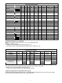
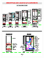
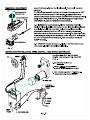
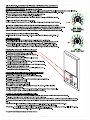
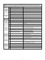
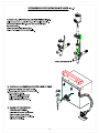
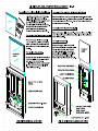
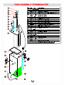
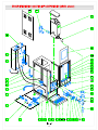
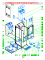
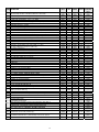
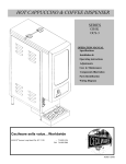
Mechanical Specifications
MODEL:
Width Depth Height Hoppers
In
In
In
Qty
Hoppers
Lb.
Tank
US Gal.
Burst
Capacity
Lit Display Area Shipping
(W X H) Sq. In. Weight Lb.
GB1M-LD
SPACE SAVER
8½
22
31 ½
1
8 SQ
2
58
(7 x 13) 91
65
GB2M-5.5-LD
GB3M-5.5-LD
GB3M-10-LD
SPACE SAVER
8½
11
11 ½
22
22
22
34
34
34
2
2.75
2.75
58
85
112
(7 x 13) 91
(9½ x 13) 123
(123/8 x 13) 164
86
100
110
14 1/8
17
17
22
22
22
34
34
34
5½
4
5½
10 P
5½
5½
5½
10 P
4
4
4
4
10
5½
4
4
4
2.75
6
6
112
140
140
(123/8 x 13) 164
(123/8 x 13) 164
(123/8 x 13) 164
120
140
140
2
2.75
3.75
3.75
6
58
58
58
58
98
(6½ x 13½) 88
(81/8x13½) 110
(12½x12) 150
(12½x12) 150
(12½x12) 150
70
81
120
125
130
2
2.75
2.75
58
58
58
(6½ x 13½) 88
(6½ x 13½) 88
(93/4 x 12) 117
70
75
100
14 SQ
2.75
8.5
8.5
8.5
93
131
150
150
(7 x 13) 91
(123/8 x 13) 164
(123/8 x 13) 164
(123/8 x 13) 164
85
140
155
155
2K-GB-LD
3K-GB-LD
4K-GB-LD
5K-GB-LD
5K-10-GB-LD
BUDGET
8½
10
15 5/8
15 5/8
18
20
20
20
20
20
31 ½
31 ½
31 ½
31 ½
34
GB2-LP-LD
GB3-LP-LD
GB4-LP-LD
LOW PROFILE
8½
11
141/8
20
20
20
27 ½
27 ½
27 ½
2
3
2
1
4
5
4
1
2
3
4
5
1
4
2
3
4
GB1SKI -LD
GB2-SKI -LD
GB2 Super SKI
GB2 Super SKI-BL-LD
SKI
8½
14 1/8
14 1/8
14 1/8
23 1/4 38
23 1/4
38
24 1/4 40 ½
24 1/4 40 ½
1
2
2
2
GB4M-5.5-LD
GB5M-5.5-LD
GB5M-10-LD
SKI
SUPER SKI
SUPER SKI
14 SQ
14 SQ
14 SQ
All models are with or without -LD (Lit Display).
Height: Add an additional 1” when installing with 1” feet or 4” when installing with 4”legs.
Plumbing: ¼” water line required.
** Clearance: Add 2" for line cord and valve fitting in the back of unit
* Burst Capacity: Max. # of drinks dispensable with available hot water - based on 6 oz. cups.
Electrical Specifications
Model No.
ALL MODELS
ALL MODELS
ALL EXPORT MODELS
Volts
120V
120/240V
220V
Phase
1
1
1
Hz
60
60
60
Watts
1.8KW
3.0KW
3.0KW
Number of
Heaters
1
1
1
Amps
15
15
15
Receptacle
Nema No.
5-15R
L14-20R**
††
Circuit
Breaker
15A
20A
20A
GB3\4\5\SKI\Super SKI
120/240V
1
60
6.0KW
2
25
L14-30R**
30A
GB Super SKI
230V
1
1
3
60
9.0KW
18.0KW
18.0KW
3
39
78
45
HARDWIRE
50A
100A
60A
120V, 1.8 KW, 15A, Nema 5-15R standard on all models; 3.0 KW and 6.0 KW, 120/240V units available.
** 120/240V, 3 pole, 4 wire grounding type Twist-Plug Receptacle.
For 240V units, use L6-20R or L6-30R, 2 pole, 3 wire Twist-Plug Receptacle.
†† 220V Export Receptacle to be specified where order is placed.
For Wiring, refer to Wiring Diagrams in back of manual. See Electrical Data Label attached to the back of the unit for proper voltages,
breaker sizes and electrical outlet requirements for each model number listed.
2
INSTALLATION INSTRUCTIONS
Water Inlet Connection:
This equipment is to be installed to comply with the applicable Federal, State, or local plumbing codes having jurisdiction. In addition:
1. A quick disconnect water connection or enough extra coiled tubing (at least 2x the depth of the unit) so that the machine can be moved
for cleaning underneath.
2. An approved back flow prevention device, such as a double check valve to be installed between the machine and the water supply.
The GB beverage dispenser is equipped with a ¼" Flare Water Inlet Fitting which is located on the left side in the back of the base (when
looking at the machine from the front).
HIGHLY RECOMMENDED:
A WATER SHUT-OFF VALVE and A WATER FILTER, preferably a combination Charcoal/Phosphate Filter, to remove odors and inhibit lime
and scale build up in the machine.
Note: In areas with extremely hard water, a water softener must be installed in order to prevent a malfunctioning of the equipment and in
order not to void the warranty.
After the machine has been unpacked and placed on a counter, pull out the stainless steel drip tray. It should contain the following:
A Set of 4 Adjustable Leveling Legs & Water Inlet Fitting.
START-UP PROCEDURE
Caution: Make sure that the Heater Switch, located behind right hopper with door opened, is in the OFF position.
1.
2.
3.
4.
5.
6.
Connect the ¼" dia. copper waterline to the ¼" flare water inlet fitting of the valve.
Plug the power cord into a proper receptacle.
Activate the Power Switch (Toggle Up). The door display panel, the red power indicator light and the green dispense buttons will light
up and the tank will start filling. Allow approximately 4-5 minutes for the tank to fill.
Activate the Heater Switch. Allow approximately 10-30 minutes for the water to reach a temperature of 195°F. The heat up time will
depend on the water inlet temperature, the input voltage and the wattage of the elements in the machine.
Place a 6 oz. or larger cup under the left dispense nozzle, press and hold the left dispense switch for 6 seconds. The machine will
dispense water at the rate of 1 oz. per second. Repeat it several times to check for consistent output. Repeat same for the other
dispense switches. This procedure checks that the dispense valves are not air-locked.
While the tank is heating up, remove the hoppers, load them with products and reposition them back in the machine. When the green
ready light comes on, the tank has reached its brew temperature and the machine is ready to dispense the first cup of Cappuccino.
To Dispense a Cup of Cappuccino or Coffee or Soup: Place a 8 oz. or larger cup under selected drink dispense nozzle.
For Manual units: Push and hold brew button until cup is 2/3 full, then release button.
For Automatic units: Press and Release button. Cup will fill up automatically to it’s preset amount.
See Drink Strength Adjustments if different levels of drink strength are desired or Programming Dispense Volume if different cup sizes
are used.
3
UNPACKING INSTRUCTIONS
Carefully unpack the GB Machine and inspect immediately for shipping damage. Your GB Machine was
shipped in a carton designed to give it maximum protection in normal handling. It was thoroughly inspected
before leaving the factory. In case of damage, contact the shipper, not Cecilware.
DESCRIPTION AND LOCATION OF COMPONENTS
Note:
Refer to Illustration A for description and location of COMPONENTS and CONTROLS.
1.
HOPPERS. Depress the door latch on the left side of the door and pull door open to access the hoppers.
The hoppers hold up to 14 lbs. of Cappuccino product and up to 1.5 lbs. of freeze dried coffee product , depending on model number
(see spec. sheet).
To remove the hoppers simply swing the top compartment door open and lift out the hoppers.
To reposition the hoppers in the compartment, slide the hopper base back between the rails until the ¼" pin at the bottom of the hopper
base falls into the ¼" positioning hole of the compartment base cover.
2.
RINSE SWITCH. With the door open, the rinse switch is located on the left side the first Whipper chamber.
In the RINSE position it disengages the hopper motors and allows only water to be dispensed.
It is used for flushing out the Whipper Chambers and to adjust the water dispense valves for proper flow rates.
3.
HEATER SWITCH. This switch is located inside the cabinet behind the right hopper, open door and remove right hopper to
access it. Its primary function is to shut off the heating element during the initial priming, start up operation of the machine, or
whenever the tank is being drained for service.
Note: On 120V, 1.8 KW and 120/240V, 3 KW machines, the Power Switch and Heater Switch must be ON
in order for the elements to operate.
4. POWER SWITCH. This switch is located on the left side of the splash panel below the door. On 120V, 1.8 KW and 120/240 or 240V, 3
KW single element machines the power switch controls all power to the machine including the heater elements.
Note: On 120/240V, 6 KW machines , the Power and Heater Switches are independent of each other. Both switches must be
OFF in order for the machine to be completely shut down.
5.
WATER LEVEL CONTROLS:
Under normal conditions and operation, the water level in the tank should not drop more than ½" from the probe. If it does, the tank is
not refilling fast enough. Check the water line and water filter, they may need cleaning or replacing.
1. Solid state water level control board
2. Water inlet valve
3. Dual Water level probe
Part# L690A
Part# L462A
Part# K695Q
4
5
6
7
8
9
Model L690A (Rev. B) Dual Probe Liquid Level Controller
Overview - The L690A is a Dual Probe Liquid Level Controller designed to maintain a specific level of water in
the tank. This device utilizes two level probes for increased reliability. Independent maximum fill timers are
incorporated in the controller for overflow protection.
Operation - When a fill problem occurs, the Dual Probe Liquid Level Controller turns OFF power to the fill valves
and remains OFF until the power input is reset (i.e. turn power switch off then back on).
Low Level Probe - When the Low Level Probe detects the absence of water for two seconds, the Controller
immediately opens the Fill Valve. When the Low Level Probe detects the presence of water the Controller
immediately closes the Fill Valve.
High Level Probe - When the High Level Probe detects the absence of water the Controller immediately turns ON
and the Low Level Probe is allowed to control the Fill Valve. When the High Level Probe detects the presence of
water for 1.5 seconds the Controller turns OFF power, which closes the Fill Valve.
Maximum Fill Timers – On the first fill, the unit will only allow 15 minutes of continuous filling if neither of the
Level Probes has detected the presence of water since power has been applied (i.e. first fill). Once the presence of
water has been detected the unit will only allow 10 minutes of continuous filling to prevent flooding. If the duration
of continuous filling exceeds the allotted time then a Fatal Error is generated, which closes the inlet valve.
Status LED – Located on the Controller, this indicator is turned ON for one second after power is applied to
indicate a functioning unit. The indicator will blink when the High Level Probe detects water to signify a warning.
During a Fatal Error the indicator will be ON continuously.
9a
TROUBLESHOOTING GUIDE
WARNING: To reduce the risk of electrical shock unplug the dispenser power cord before repairing or replacing any internal
components of the unit.. Before any attempt to replace a component be sure to check all electrical connections for proper contact.
PROBLEM
PROBABLE CAUSE
REMEDY
1
A Dispensing unit unplugged
Reconnect dispensing unit
Light Display
B No power from Terminal Block
Check the Terminal Block for loose wire
not lit.
C Defective Bulb
Replace Bulb.
No power.
D Defective Ballast.
Replace Ballast.
2
No water when
Rinse Switch is
ON.
3
No product when
Dispense Button
is
pressed
4
Water does not
shut off.
Water keeps
dispensing.
E Loose Bulb in socket.
Make sure bulb is seated properly in socket.
A Water supply OFF.
Turn water ON.
B Clogged inlet screen (Water Inlet Valve).
Disconnect water line and clean inlet screen.
C Inoperative Water Inlet Valve.
Check connection, if needed replace Valve.
D Loose electrical connection.
Check all electrical connections.
A No product in Hopper.
Add product.
B Auger not working.
Engage Hopper/Nut to Motor Gear (See ill. B).
C Damaged, loose, or missing Agitator Gear.
Replace Agitator Gear (See ill. B).
D Inoperative Auger Motor or Relay.
E Hopper outlet clogged
Check connections of Motor, Relay and/or Switch, if needed replace
components.
Clean Hopper and check Cartridge Heater.
F Faulty Coupling.
Replace damaged Coupling components.
A Leaking Water Inlet Valve.
Clean/check fittings of Water Inlet Valve. Replace Water Inlet Valve
if needed. See ”Water Inlet Valve Test”
Check Switch connections. Replace Dispense Switch if needed.
B Inoperative Dispense Switch
C Inoperative Rinse Switch
Check Rinse Switch connections.
Replace Rinse Switch if inoperative.
Clean or unclog Water Dispense Valve.
Replace Dispense Valve if inoperative.
Check Solenoid. Replace if necessary.
See “Water Inlet Valve Test”.
Check Probe. Replace if necessary. See “Probe Test”
D Clogged/stuck Water Dispense Valve
5
A Water Inlet Valve malfunction.
No water is
going into tank at B Water Level Sensor/ Probe malfunction.
all.
C Solid State Water Level Control Board
Check Water Level Controls. Replace if necessary.
See “Water Level Control Test”.
Check Probe. Replace if necessary. See “Probe Test”.
6
A Water Level Probe malfunction.
Water will not B Solenoid (Water Inlet Valve) malfunction.
stop flowing into
water tank.
C Solid State Water Level Control malfunction
7
Water is not
heating up in
the water tank.
A Heater Switch is OFF.
Check Solenoid. Replace if necessary. See “Water Inlet Valve
Test”.
Check The Water Level Controls. Replace if necessary.
See “Solid State Water Level Control Test”.
Turn Heater Switch ON.
B Thermostat is OFF.
Turn Thermostat ON. (See ill. C) Turn Knob Clockwise.
C Loose connection on Thermostat.
Make sure all wires and terminals on Thermostat are tight.
D Hi-Limit Temperature Switch is defective
Replace the Hi-limit.
E Heater is burned out or defective.
Replace the Heater.
10
SANITIZING:
All sanitizing agents in the food zone must comply with 21 CFR 178.1010.
All food dispensing units should be sanitized periodically. All parts to be sanitized must be cleaned first.
To prepare a sanitizing solution:
ADD 2 TSP. OF LIQUID CLOROX BLEACH (5.25% CONCENTRATION) TO 1 GALLON OF WATER AT ROOM TEMPERATURE (70°90°F).
Note: Always start with a unopened bottle of Clorox Bleach since the solution from an opened bottle has a short life span.
• Soak all parts for a minimum of 3 min. in the sanitizing solution.
• Let all sanitized parts drain and dry naturally. DO NOT WIPE THEM DRY.
• Before using the sanitized unit (or parts) with food stuffs, rinse all parts thoroughly with water.
Water pipe connecting and fixtures directly connected to a potable water supply shall be sized, installed, and maintained in accordance with
Federal, Sate, and Local codes (section 7).
Cleaning
1. Turn the power switch to OFF.
2. Remove the drip tray with grill and empty the contents.
3. Wash and let dry the tray and grill (use a mild dishwasher detergent).
4. Wash and let dry the dispense area.
5. Turn the power switch to ON.
Cleaning the Hoppers (See Hopper Illustration)
1. Open the cabinet door and raise the top cabinet lid.
2. Take the hopper out of the cabinet.
3. Pull off the elbow chute and remove the hopper cover.
4. Unscrew the auger gear CW while holding steady the auger inside the hopper. Take out the auger, agitator wheel, and spring.
5. Rinse each item thoroughly. Wash & scrub Hopper and Agitator Wheel recesses with Bristle Brush.
6. Let dry all items and reassemble.
Filling the Hoppers
1. Open the cabinet door, raise the top cabinet lid.
2. Fill each hopper with the correct product. Note: Hoppers can also be removed for filling.
3. Reposition hoppers in the hopper compartment, making sure the hoppers are properly seated.
Flushing the Whipper Chamber
1. Open the cabinet door and turn the RINSE switch to ON.
2. Place a container under each dispense nozzle and push the dispense switches.
Note: On manual dispense machines, push and hold the dispense buttons for 10 seconds.
3. Open the cabinet door and turn the Rinse switch back to OFF.
4. Wash and let dry the splash panel.
5. Remove the drip tray, wash and let dry thoroughly.
Removing and Cleaning the Cappuccino Whipper Chambers (See Hopper Illustration)
1. Remove the dispense cap by pulling it forward and at the same time twisting it clockwise.
2. Grab and pull the mixing bowl out of the mixing bowl socket.
3. Grab and twist the whipping chamber clockwise and pull it off the mounting plate.
4. Pull the Whipper Blade off the motor shaft. Notice the flat keyway on the shaft and the matching keyway inside the Whipper blade shaft.
It is important that these two keyways are lined up when re-assembling the components.
5. Twist the mounting plate clockwise and pull it off the motor shaft.
6. Slip off the o-ring from the Whipper Chamber mounting plate and clean o-ring and o-ring seat.
Removing and Cleaning the Coffee/Tea Mixing Chambers (See Hopper Illustration)
1. Remove the dispense cap.
2. Pull the mixing bowl out of the mixing bowl socket.
3. Take out the extension tubes.
4. Rinse them thoroughly
11
12
14
15
16
17
18
ITEM DESCRIPTION
1
GB-LP
TANK ASS’Y/TANK TOP ASS’Y -SEE METAL PARTS LIST – NEXT PAGE
Å
Å
Å
M326A
M326A
M326A
-------
M324A
M326A
L463A
K178A
CD257
------C032S
60105
----L690A
-------B129A
CD56A
CD224
CD214
M172A
Å
L069A
C002A
Å
Å
CD75A
CD124
CD66A
CD65A
M379A
CD64A
M467A
CD63A
CD137
CD61A
M378A
CD67A
L455A
---B216A
CE82A
CB04A
------M367A
Å
N978A
----------
M324A
M326A
L463A
K178A
CD257
------C032S
60105
L533A
L690A
-------B129A
CD56A
CD224
CD214
M042A
Å
L069A
C002A
Å
Å
CD75A
CD124
CD66A
CD65A
M379A
CD64A
M467A
CD63A
CD137
CD61A
M378A
CD67A
L455A
CE221
CE220
CE76A
---B128A
L396A
M367A
Å
N978A
----------
M324A
M326A
L463A
K178A
CD257
------C032S
60105
---L690A
-------B129A
CD56A
CD224
CD214
M042A
Å
L069A
C002A
Å
Å
CD75A
CD124
CD66A
CD65A
M379A
CD64A
M467A
CD63A
CD137
CD61A
M378A
CD67A
L455A
CE221
CE220
CE76A
---B128A
L396A
M367A
Å
N978A
----------
----
----
----
----
CD70A
CD68A
CD98A
CD175
---Å
CD70A
CD70A
CD120
CD152
CD175
----Å
CD70A
M324A
M326A
----A4256
L022A
C396A
CE181
CG99A
B157A
CG12A
L690A
CE187
L556A
CF29A
B129A
--CD224
CG14A
M042A
Å
L069A
C165A
Å
Å
CD75A
CD124
CD66A
CD65A
M379A
CD64A
M467A
CD362
CD137
CD61A
M378A
CD67A
L584A
CE221
CE220
CE76A
---B128A
L396A
M367A
Å
N978A
NF58A
L576A
---L557A
NF30A
CD90A
CD105
CD105
CD175
--Å
----CD151
Å
SILICONE HOSE [BREATHER FITTING] [ .375 I.D x 32”] M326A
SILICONE HOSE [DISPENSE VALVE] [ .313 I.D x 14.5”] M324A
SILICONE HOSE [WATER INLET] [.375 I.D. x 13”] M326A
CHECK VALVE [PREVENTS BACKFLOW] [suggested – not supplied]
HOSE NUT ASS’Y OR FITTING
WATER INLET VALVE 120 [120/240 ]
FUSE HOLDER (120/240V only)
BUSSMAN SC15 FUSE (GBs 120/240V only)
POWER CORD ( C032S 120V, 15AMP; CG99A 240V, 30 AMP)
TERMINAL BLOCK FOR 120V [WAS B117A]
[FOR 240V USE B116A]
CONTACTOR GB5M & GB2-SKI SUPER
WATER LEVEL CONTROL BOARD, DUAL ( L706A 220V) [was Single L398A120V & L399A 220V]
STEPDOWN TRANSFORMER (240/120V only)
SPEED CONTROL BOARD [Controls Auger Speed GRAM THROW]
TRANSFORMER [use w/DC motor & Speed Control CCA]
RELAY, OMRON
FAN CD56A & ELBOW INSERT CD108 [USE FOR GB1, 2, 3 ONLY]
FAN CD224 w/ RW31Q Fan Housing Ass’y [GB4,5, SKI ]
DUCT HOSE [for Exaust Fan]
1” FEET or 4” LEGS M172A (SET OF 4)
RINSE SWITCH [GB1 & GB5 - L069A; GB2 -L299A; GB3-L446A; GB4 L470A ]
POWER SWITCH & HEATER SWITCH (120V) OR [FOR 120/240V USE L299A]
HEATER INDICATOR LIGHT (amber C002A, red C165A)
GRILL -SEE METAL PARTS LIST– see next page
DRIP TRAY-SEE METAL PARTS LIST – see next page
WHIPPER MOTOR-short shaft
SLINGER DISC
GROMMET CHAMBER MOUNTING
CHAMBER MOUNT
“O” RING # 125 (used w/ grommet CD66A)
WHIP BLADE
EXTENSION TUBE PLASTIC
WHIP CHAMBER (Straight – CD63A) OR (Slanted – CD362)
MIXING CHAMBER [ALTERNATE CD62A W/ RECTANGULAR WING]
DISPENSE CAP OR SPLASH GUARD
“O” RING (#110) (used w/socket CD67A)
MIXING BOWL SOCKET
DISPENSE BUTTON (GB L455A) / (GB Ski Super L584A) STOP SWITCH
BALLAST [ for inside door parts see ill. E]
LAMP HOLDER [ for inside door parts see ill. E]
BULB [ for inside door parts see ill. E]
O-RING [use with bulb CE82A only ]
STARTER BASE [ for inside door parts see ill. E]
STARTER, TYPE FS- 5, 5-6-8 WATT [ for inside door parts see ill. E]
DOOR LATCH
DOOR ASS’Y -SEE METAL PARTS LIST – see next page
CLEANING INSTRUCTIONS
PROGRAMMING INSTRUCTIONS
TIMER “TEACH ME” [PROGRAM. dispense Time/Cup Size]-Single [Triple L582A] or
TIMER [NOT PROGRAM.] [use w/pot. L577A & dial/cup size labels: NF32A/33A/34A
POTENTIOMETER - USED W/SPEED CONTROL BD [GRAM THROW DIAL]
LABEL, GRAM THROW DIAL- [GB2 NF30A; GB3 ND81A; GB4 NF31A]
PRODUCT GUIDE
CANISTER ASS’Y WITH COVER [w/NYLON auger] OR
CANISTER ASS’Y WITH COVER [w/WIRE auger]
AC AUGER MOTOR (90 RPM CD73A, (44 RPM CD87A) [CD175 same as CD150]
DC AUGER MOTOR 90 RPM CD151 [W/Screw P443A] Portion Control - Optional
SIDE PANELS - SEE METAL PARTS LIST – see next page
M324A
M326A
L463A
K178A
CD257
------C032S
60105
---L690A
-------B129A
CD56A
CD224
CD214
M042A
Å
L069A
C002A
Å
Å
CD75A
CD124
CD66A
CD65A
M379A
CD64A
M467A
CD63A
CD137
CD61A
M378A
CD67A
L455A
CE221
CE220
CE76A
---B128A
L396A
M367A
Å
N978A
42
43
44
45
46
47
48
49
50
51
52
19
GB-Super-SKI
w/ Teach-Me
Timers
Å
3
4
5
6
7
8
9
10
11
12
13
14
15
16
17
41
GB-SKI
M326A
2
19
20
21
22
23
24
25
26
27
28
29
30
31
32
33
34
35
36
37
38
39
40
GBM-5.5
Å
M326A
18
GBK
CD155
CD175
---Å
METAL PARTS LIST
MODELS
ITEM 1
ITEM 23
ITEM 23
TANK ASS’Y
GRILL
SC35C
TANK TOP
ASS’Y
SC32C
RI23A
RI11A
RD03Q
RH91A
GB2M-5.5
SC35C
SC32C
RI18A
RI11A
RH47Q
RG48A
GB3M-5.5
SC36C
RI39C
RI19A
RI12A
RH48Q
RG48A
GB4M-5.5
RL72C
RL69C
RI20A
RH05A
RH49Q
RG48A
GB5M-5.5 [17” W]
SJ61C
SJ60C
SD76A
RT66A
RM02Q
RG48A
GB5M-10 [18” W]
SJ61C
SJ60C
RR34A
RR33A
SD82Q
RG48A
SC35C
SC32C
RK44A
RM21A
RF73Q
RD46A
GB1M
SPACE SAVER
ITEM 45
ITEM 53
DRIP TRAY DOOR ASS’Y SIDE PANELS
2K-GB
[32” H]
3K-GB
[32” H]
SC35C
SC32C
RK47A
RM23A
RF79Q
RD46A
4K-GB
[32” H]
RL72C
RL69C
RZ80A
RZ79A
RZ07Q
RD46A
5K-GB
[32” H]
RL72C
RL69C
RZ80A
RZ79A
RZ07Q
RD46A
SC35C
SC32C
SC25A
SC26A
SC01Q
SC33A
GB3 - LP
SC36C
RI39C
SC30A
SC31A
SB30Q
SC33A
GB4 - LP
SC36C
RI39C
SC57A
SC58A
SC62Q
SC33A
GB2 –LP
BUDGET
W/ MOLDED DOOR
ITEM 24
LOW PROFILE
GB1-SKI-LD
SKI
RL54C
RL52C
RI23A
RI11A
RF37Q
RL51A
GB2-SKI-LD
SKI
RN21C
RN16C
RL61A
RH05A
RF23Q
RL51A
GB2-Super-SKI
Super SKI
RN21C
RN16C
RQ78A
RQ16A
RN61Q
RN33A
RN21C
RN16C
RQ78A
RQ16A
RN61Q
RN33A
GB2-Super-SKI-BL-LD
21
22
23
24
25
26
27
28
29
30
31
32
33