1
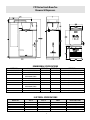
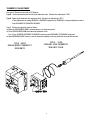
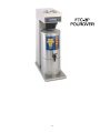
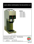
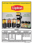
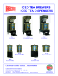
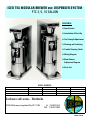
ICED TEA MODULAR BREWER AND DISPENSER SYSTEM
FTC 3, 5, 10 GALLON
CONTENTS:
• Specification
• Installation & Start-Up
• Tea Strength Adjustment
• Cleaning and Sanitizing
• Trouble Shooting Guide
• Wiring Diagram
• Brew Volume
Adjustment Diagram
• Parts List
MODEL NUMBERS:
Brewer
Dispenser only
Dispenser w/Round Stand
Capacity
FTC-3
S3C
SU-3P
3 Gallon
FTC-3.5
S3.5C
SU-3P
3.5 Gallon
FTC-5
S5C
SU-5P
5 Gallon
FTC-10
S10C
SU-10P
10 Gallon
Cecilware sells value... Worldwide
43-05 20th Avenue, Long Island City, NY 11105
• 718-932-1414
FAX. 718-932-7860
1
N866A 3/29/99
FTC-Series Fresh Brew Tea
Brewers & Dispensers
DIMENSIONAL SPECIFICATIONS
MODEL NO.
FTC-3 SHOWN ABOVE
S3C SHOWN ABOVE
SU-3P SHOWN ABOVE
FTC-5
S5C
S5W
SU-5P
FTC-10
S10C
DESCRIPTION
WIDTH (W)
DEPTH (D)
3 GAL. TEA BREWER
3 GAL ICED TEA DISPENSER
3 GAL ICED TEA DISPENSER
WITH ROUND STAND
5 GAL. TEA BREWER
5 GAL TEA DISPENSER
5 GAL TEA DISPENSER– WIDE
5 GAL TEA DISPENSER
WITH ROUND STAND
10 GAL TEA BREWER
10 GAL TEA DISPENSER
10”
9 1/2” DIA.
9 1/2” DIA.
20”
-
28 3/4”
18 3/4”
18 1/4 ”
[19 5/8 W/ BREW COVER]
[18 7/8 W/ BREW COVER]
10 1/8”
9 1/2” DIA.
12 1/4” DIA.
12 3/4” DIA.
21 1/2”
-
34 1/2”
24 3/4”
18 3/4”
18 ”
[25 1/4 W/ BREW COVER]
[19 W/ BREW COVER]
[18 1/4 W/ BREW COVER]
14 1/2”
14”
DIA.
22”
-
35”
24 3/4”
[25 1/4 W/ BREW COVER]
HEIGHT (H)
ELECTRICAL SPECIFICATIONS
MODEL NO.
FTC-3
FTC-5/10
FTC-3
FTC-5
FTC-10
VOLTS
WATTS
AMPS
NEMA LINE CORD
120
120
240
240
240
1700
1700
2,400
2,400
3,500
14.2
14.2
10.0
10.0
14.6
5-15P
5-15P
6-15P
6-15P
6-20P
2
INSTALLATION AND OPERATION INSTRUCTIONS
UNPACKING AND ASSEMBLY:
The machine is shipped with 1 funnel ass’y and a water inlet fitting.
ACCESSORIES USED WITH THE MACHINE:
Sanitary Style Iced Tea Dispenser.
WATER INLET CONNECTION:
The National Sanitation Foundation (NSF) requires the following for an NSF approved hook-up.
This equipment is to be installed to comply with the applicable federal, state, or local plumbing codes having jurisdiction.
In addition:
1. A quick disconnect water connection or enough extra coiled tubing (at least 2x the depth of the unit) so that the machine
can be moved for cleaning underneath.
2. An approved back flow prevention device, such as a double check valve to be installed between the machine and the water supply.
The FTC-3, FTC-5, FTC-10 are equipped with 1/4 flare water inlet fitting, located in the back of the unit.
Connect the ¼" dia. Copper waterline to the ¼" flare water inlet fitting of the valve.
HIGHLY RECOMMENDED: A water shut-off valve and a water filter, preferably a combination charcoal/ phosphate filter, to
remove odors and inhibit lime and scale build up in the machine.
Note: In areas with extremely hard water, a water softener must be installed in order to prevent a malfunctioning of the
equipment and in order not to void the warranty.
FTC-3
FTC-5
FTC-10
WATER INLET VALVE # 80235
3
INITIAL PRIMING - FILLING OF TANK
NOTE: DO NOT PLUG BREWER INTO POWER OUTLET UNTIL YOU ARE SURE THE HEATER SWITCH IS IN THE OFF POSITION.
Switch must remain in the OFF position until the PRIMING OPERATION has been completed. This procedure protects the Element from accidental burnout.
LOCATION OF TOGGLE HEATER SWITCH:
FTC-3, FTC-5, AND FTC-5L, FTC-10; SEE BACK OF TOP CONTROL BOX.
PRIMING PROCEDURE:
• Turn on the water supply and check for leaks at connections.
• Plug power cord into a 15 amp 120 volt grounded outlet.
• Remove sample filter pack from funnel and insert funnel back into machine.
• Position carrier under funnel making sure holes in cover line up with funnel and dilution tube.
• Push RED POWER SWITCH to ON position.
• Push GREEN BREW SWITCH and release. Water should start to flow from the DILUTION TUBE into the CARRIER.
No water will flow from the funnel until halfway through the cycle (about 5 minutes).
PRIMING AND TESTING PROCEDURE BEFORE UNIT HAS REACHED BREWING TEMPERATURE:
• Shut off heater switch [toggle down]. This will bypass the lockout circuit.
• Activate the red power switch.
• Activate the green grew switch for one complete cycle.
• At the end of one brew cycle, discard water from dispenser and reposition under brew funnel.
TOTAL VOLUME OUTPUT CHECK:
• Place empty CARRIER less Cover under funnel.
• Activate GREEN BREW SWITCH.
• At the end of brew cycle (about 10 minutes) water level inside Carrier should be within 2 inches from the top.
• If necessary adjust TIMER. See TIMER ADJUSTMENTS.
TURNING ON HEATING ELEMENTS:
• Flip the Toggle Switch in the back of the brewer to the UP or ON position.
• Allow 20 minutes to reach brewing temperature (195 F).
• When the READY LIGHT comes on, the brewer is ready to brew.
4
BREWING INSTRUCTIONS:
Place empty CARRIER under Funnel. Make sure openings in cover line up properly with funnel outlet and dilution tube.
TEA BAGS - Place correct number of tea bag(s) directly into brew funnel.
Replace funnel into brew head of unit and push brew switch when GREEN READY LIGHT comes on.
GROUND TEA LEAVES - Place paper filter into brew funnel and add proper amount of fresh ground tea leaves into filter.
Replace funnel into brew head of unit and push brew switch when GREEN READY LIGHT comes on. See chart
below for the recommended ounces of ground tea leaves.
TEA BREWING RECOMMENDED MEASUREMENTS
MODEL #
FTC-3
FTC-5
FTC-10
SIZE & QUANTITY OF TEA BAGS
(1) 3 Gallon Bag
(2) 3 Gallon Bags or (6) 1 Gallon Bags
(3) 3 Gallon Bags or (9) 1 Gallon Bags
GROUND TEA LEAVES - OUNCE
3-4 Ounces
4-6 Ounces
9 Ounces
Allow approximately 10 minutes for a complete brew cycle. DO NOT remove brew funnel until it has stopped dripping.
Serve Fresh Brewed Tea from dispensing faucet into tea glass over ice.
ADJUSTMENTS TO BE PERFORMED BY QUALIFIED SERVICE PERSONNEL ONLY.
CAUTION: BREWERS SHOULD BE UNPLUGGED FROM ELECTRICAL OUTLETS
BREW VOLUME and STRENGTH ADJUSTMENTS:
The water flow rate coming from the hot water tank is constant/fixed at 0.75 gal/min.
Increasing or decreasing the amount of hot water dispensed from tank can also be used to adjust the strength of the tea.
Longer water flows – More water – Weaker tea; Less water flows – Less water – Stronger tea.
TIMER ADJUSTMENTS FTC-3, FTC-5:
• Remove top cover and Locate Timer on the left side.
• To brew MORE tea: Turn timer knob one increment CLOCKWISE.
To brew LESS tea: Turn the timer knob one increment COUNTERCLOCKWISE.
• Go through a COMPLETE brew cycle. Repeat if necessary.
“TEACH ME” TIMER L576A ADJUSTMENTS – FTC 10:
This timer can be programmed from the brew button to dispense different volume of hot water .
PRIMING:
1.
2.
3.
4.
PUT TIMER INTO PROGRAM MODE:
1. START WITH POWER OFF.
2. WHILE HOLDING DOWN BREW BUTTON, TURN POWER ON.
3. RELEASE DISPENSE BUTTON.
PROGRAM THE BREW BUTTON:
4. PUSH BREW BUTTON TO START TIME [porduct begins dispensing].
5. PUSH BREW BUTTON AGAIN TO STOP TIME [about 2“ from top of dispenser for 10 gal.]
[product stops dispensing] .
6. BREW BUTTON CAN BE JOGGED TO TOP OFF CONTAINER.
PUT TIMER INTO RUN MODE:
7. TURN POWER OFF AND ON AGAIN [this locks in total dispense time].
MAKE SURE HEATER SWITCH IS OFF.
PUSH & HOLD DOWN BREW BUTTON WHILE SWITCHING POWER ON.
RELEASE BREW BUTTON.
PUSH BREW BUTTON AGAIN & WAIT FOR WATER TO START FLOWING OUT OF SPRAY HEAD.
NORMAL OPERATION: TURN POWER ON, TURN HEATER SWITCH ON, WAIT 20 MINUTES UNTIL READY LIGHT COMES ON. UNIT IS READY TO BREW.
5
FIG. DESCRIPTION
1
2
3
4
5
6
FIG
.
1
2
3
4
5
6
7
DETAIL A & B
6
PART
NO.
3/8 O.D. x 21 1/2 L. 77279
3/8 O.D. x 7”
77426
3/8 O.D. x 9 1/4 L. 77246
3/8 O.D. x 4 1/2 L. 77277
3/8 O.D. x 10 1/2 L. 77243
3/8 O.D. x 10 1/2 L. 77243
DESCRIPTION
PART
NO.
1/2 O.D. x 16” L.
M283C
1/2 O.D. x 10” L.
M281C
1/2 O.D. x 4” L.
M286C
1/2 O.D. x 5 1/2” L. M274C
3/8 O.D. x 11” L.
M284C
3/8 O.D. x 9 1/4 “L. 77246
3/8 O.D. x 10 1/2”L. 77243
DETAIL B
DETAIL B
FTC-3/5 FUNNEL ASS'Y #V236A
RESTRICTOR #K604A [orifice Ø .086]
WHITE FUNNEL #V211A
TEA LABEL
FTC-3
BREW FUNNEL ASS'Y
FOR FTC-3, FTC-5
ICE TEA BREWERS
MODEL NO. LABEL
FTC-3
CAUTION LABEL #N816A
FTC-10 FUNNEL ASS'Y #Q183Q
GROMMET M461A [.446 ID]
TEA SHELF- RW98A
SIPHONING TUBE #K626A [orifice Ø .187]
FUNNEL # Q183A
7
THERMOSTAT ADJUSTMENT
Two types of Thermostats are used on FTC Brewers:
Type A - Surface mounted thermostat with slotted adjustment stem. Should not be adjusted past 195º F.
Type B - Capillary bulb thermostat with adjustment knob. Should not be adjusted past 203º F.
If field adjustments are needed, INCREASE or DECREASE temperature by GRADUALLY rotating the adjustment stem or
knob CLOCKWISE OR COUNTER-CLOCKWISE.
Type B - Thermostats can be fine-tuned as follows:
• Make sure ADJUSTMENT KNOB is turned clockwise to its maximum position.
• Pull off ADJUSTMENT KNOB and locate small adjustment screw.
Turn 1/4 turn COUNTER-CLOCKWISE TO INCREASE temperature and CLOCKWISE TO DECREASE temperature.
• When GREEN BREW LIGHT comes on, take all temperature readings at the spray head with the spray head removed.
TYPE A - 59016
SURFACE MOUNT THERMOSTAT
OLDER UNITS
TYPE B – L532A
CAPILLARY– BULB THERMOSTAT
NEW UNITS 7/24/98
8
CLEANING AND SANITIZING INSTRUCTIONS
A. MACHINE: Wipe exterior of dMachine with a soft damp cloth.
B. DISPENSER [ICED TEA CONTAINER]: Wash tea carrier with mild soap and warm water.
Rinse thoroughly and replace on stand.
PROPER CLEANING AND SANITIZING OF THE FAUCET ON YOUR TEA DISPENSER IS NECESSARY TO DELIVER GREAT TASTING FRESH BREWED ICED TEA. TOMLINSON SPB/SPBH FAUCET DO NOT REQUIRE TOOLS FOR CLEANING AND SANITIZING.
TO PREVENT BACTERIAL GROWTH FOLLOW STEP BY STEP SEQUENCE AND REFER TO THE DIAGRAM BELOW.
IMPORTANT: TO PREVENT BACTERIAL GROWTH AND PROTECT TEA FLAVOR, CLEAN AND SANITIZE TEA BREWING AND
STORAGE EQUIPMENT AT LEAST ONCE A DAY AS FOLLOWS:
CONTAINER:
1. Iinside Surface - Using hot water and dishwashing detergent,
scrub interior of container with a bristle brush, including corners and bottom, to remove residues, then rinse thoroughly.
2. Outside Surface - Wash surface with sponge unsing hot water and dishwashing detergent.
FAUCET:
1. Remove the entire upper assembly of faucet by unscrewing
the bonnet.
2. Pull seat cup off from inside the upper assembly of fauset.
Inspect for war or hardening. Replace if necessary.
Clean all parts, including faucet body in hot soapy water.
Sanitize with chlorine [50 ppm], iodine [14 ppm] or quaternary
ammonium compount [100 ppm].
Air dry unit, do NOT wipe.
3. snap seat cup over stem by applying direct pressure.
4. Screw upper assembly back onto the lower assembly of faucet. HAND TIGHTEN ONLY.
NOTE: To dismantle all parts of the faucet upper assembly, apply pressure on the bottom of plastic cup, while pulling
on top handle. reassemble in reverse.
9
600 Series Pinch Tube Faucet
The Pinch Tube Faucet is used with a super-sanitary, disposable bag and tube. The tube is inserted through the faucet; product does not contact the valve. The pinch tube requires not cleaning.
Faucet Assembly Instructions:
1. Assemble faucet body [1] to existing shank [2]
2. Place handle in lock open position [3].
3. Feed the tube from bag [4] through shank [2] and through faucet body [1].
Pull tube completely through faucet so the bag is flush with the shank on the inside of the container.
4. Return handle to closed position [5].
5. Cut excess tube from bag so only 1/2” extends beyond the end of the faucet.
Cleaning Instructions:
Since each bag and tube is discarded after use, this valve requires virtually no dayly cleaning.
However, should cleaning be required, follow these steps:
With handle in lock open position [3]
1. Remove bag and tube assembly from container.
2. Remove entire upper assembly by unscrewing the bonnet [6].
3. Clean all parts, including faucet body and bushing in hot soapy water.
4. Sanitize with chloring [50 PPM], Iodine [14 PPM], or quaternary ammonium compound [100 PPM].
5. Rinse with clear hot water.
6. Screw upper assembly back onto body [hand tighten only], leaving handle in lock open position [3].
7. Follow assembly steps above.
IMPORTANT: To prevent bacterial growth
and protect tea flavor, clean and sanitize tea
brewing and storage equipment at least ONCE
A DAY according to manufacturer’s directions.
10
TROUBLE SHOOTING GUIDE FOR FTC BREWERS
PROBLEM
PROBLEM CAUSES
REMEDIES
NO WATER WHEN BREW
SWITCH IS ACTIVATED
A) DISPENSER UNPLUGGED
B) CIRCUIT BREAKER OFF OR TRIPPED
C) POWER SWITCH OFF
D) INOPERATIVE DISPENSE SWITCH
E) INOPERATIVE TIMER
F) HOT WATER TANK NOT FULL
G) WATER SUPPLY OFF
H) INLET SCREEN PLUGGED
I) INOPERATIVE INLET WATER VALVE
J) LOOSE ELECTRICAL CONNECTION
A) PLUG IT IN
B) RESET BREAKER
C) PRESS “RED” POWER SWITCH
D) REPLACE SWITCH
E) REPLACE TIMER
F) REFER TO TANK FILLING INSTRUCTIONS
G) TURN ON WATER
H) REMOVE SCREEN AND CLEAN
I) REPALCE WATER VALVE
J) CHECK ALL ELECTRICAL CONNECTIONS FOR
CONTACT
WATER DOES NOT SHUT OFF
A) LEAKING INLET WATER VALVE
B) BREW SWITCH STUCK
C) FAULTY TIMER
A) REPLACE VALVE
B) REPLACE SWITCH
C) REPLACE TIMER
WATER LEAKS FROM TANK
VENT TUBE
A) DILUTION TUBE BLOCKED OR LIMED UP
B) VACUUM TEE PLUGGED
A) REMOVE TUBE AND
CHECK FOR BLOCKAGE
B) REMOVE TEE AND
CHECK FOR BLOCKAGE
WATER FROM SPRAY HEAD
NOT HOT
A)
B)
C)
D)
E)
A)
B)
C)
D)
E)
TEA TOO WEAK
A) TOO MUCH WATER (IN EXCESS OF 3 GALLONS)
HEATER SWITCH IN “OFF” POSITION
INOPERATIVE THERMOSTAT
INOPERATIVE HEATING ELEMENT
INOPERATIVE HIGH LIMIT
LOOSE ELECTRICAL CONNECTION
B) ADJUSTOR ASSEMBLY OUT OF ADJUSTMENT
C) BREW WATER NOT ENOUGH
D) SPRAY HEAD LIMED UP
TURN ON SWITCH
REPLACE THERMOSTAT
REPLACE HEATING ELEMENT
REPLACE HIGH LIMIT
CHECK ALL ELECTRICAL CONNECTIONS
A) TURN TIMER COUNTER-CLOCKWISE AND REBREW.
REPEAT UNTIL DESIRED STRENGTH IS ACHIEVED
B) REFER TO ADJUSTOR ASSEMBLY INSTRUCTIONS
C) TURN UP THERMOSTAT
D) REMOVE SPRAY HEAD AND DELIME.
WHEN REPLACING SPRAY HEAD. TIGHTEN
ONLY WITH FINGERS
TEA TOO STRONG
A) NOT ENOUGH WATER (LESS THAN 3 GALLONS)
A) TURN TIMER KNOB COUNTER-CLOCKWISE
AND RE-BREW. REPEAT UNTIL DESIRED
STRENGTH IS ACHIEVED
WATER BOILS
A) MALFUNCTIONING THERMOSTAT
B) THERMOSTAT NOT CONTACTING TANK
A) REPLACE THERMOSTAT
B) TIGHTEN RETAINING NUTS
FUNNEL OVERFLOWS
A) ADJUSTER ASSEMBLY SET TOO HIGH
B) BREW FUNNEL CLOGGED
A) REFER TO ADJUSTOR ASSEMBLY INSTRUCTIONS
B) REMOVE RESTRICTOR SCREEN ASSEMBLY &
CLEAN
11
12
REPLACEMENT PARTS LIST FOR TEA BREWER FTC-3, FTC-5, FTC-5L, FTC-10
ITEM DESCRIPTION
FTC-3
PART NUMBERS
FTC-5 / FTC-5W FTC-10
1
2
3
4
5
6
7
TOP COVER
HOSE .312 ID. 7.25” LONG
FLOW CONTROLLER, HOT SIDE, BLACK [orifice Ø.078]
SPRAY HEAD FITTING
WASHER FLAT 9/16 ID
SILICON WASHER 9/16 ID
TIMER 120V [“TEACH ME” TIMER–FTC-10]
40941
M324A
M647A
95138
P175A
M197A
L264A or L265A
40941
M324A
M647A
95138
P175A
M197A
L201A
R554A
M324A
M647A
95138
P175A
M197A
L576A
8
9
10
11
THERMOSTAT [WAS 59016– MOUNTED ON TANK]
RELAY – TEMPERATURE LOCKOUT – OPTIONAL FEATURE
SWITCH PANEL
BREW SWITCH 120V
L532A
L539A
R741A
L383A
L532A
L539A
R741A
L383A
L532A
L539A
R741A
L383A
12
13
DECAL
POWER SWITCH 120V
15547
L155A
15547
L155A
15547
L155A
14
15
16
17
SPRAY HEAD NUT
SPRAY HEAD
DILUTION TUBE ASSEMBLY
RESTRICTOR W/SCREEN [orifice FTC 3/5 Ø.086 / FTC-10 Ø.187]
K107A
09296
97281
K604A
K107A
09296
H209A
K604A
K107A
09296
H210A
K626A
18
BREW FUNNEL – WHITE POLYCARBONATE [ S.S. FOR FTC-10 ]
V211A
V211A
Q183A
19
20
21
22
23
24
25
26
BRACKET, TO CENTER POT
TOWER
BASE TOP
BASE BOTTOM
RUBBER BUMPER
TINNERMAN NUT
WATER VALVE INLET
REAR BOTTOM COVER
POWER CORD 120V
73372
41023
R708A
R709A
M098A
03016
80235
41027
C032A
73372
41023
R708A / RV49A *
R709A / RV50A *
M098A
03016
80235
41027 / RT90A *
C032A
73372
R533A *
R536A *
R537A *
M098A
03016
L022A
R512A *
C032A
27
STRAIN RELIEF 120V
57032
57032
57032
28
29
30
31
HOSE NUT ASS’Y [WATER INLET]
BACK PANEL
HEATER SWITCH W/ WASHER AND NUT
SWITCH GUARD S.S. [or 15589]
K491A
41024
L069A
U810A
K491A
41024
L069A
U810A
K020A
R534A
L069A
U810A
13
14
TANK ASSEMBLY
ITEM
1
2
3
4
5
6
7
8
9
11
12
13
14
15
16
17
18
19
20
21
22
PART NO.
FTC-3
FTC-5
FTC-3 LIPTON
97131
97131
97131
06121
06121
06121
K538A
K538A
K538A
P493A
P493A
P493A
M641A
M641A
M641A
97214
97214
97214
97215
97215
97215
20039
20039
20039
87037
G014C
87037
03011
03011
03011
97132 / 97300 97132 / 97300 97289
80224
80224
80224
59010
59024
59010
59016
L532A – PROBE ONLY 59016
—
73276
73276
—
38205
38205
—
09295
09295
10054
10054
10054
97221
97221
K240A
M279A
M279A
M279A
03053
03053
03053
PART DESCRIPTION
TANK CLAMP
TANK CLAMP BOLT
TUBE, WATER OUTLET [TO SIPHONING TUBE]
GRIP RING [WALDES MFR P/N 5555-25H] [.25 ID]
GROMMET [.466 ID]
TANK TOP
TANK BAFFLE
TANK BAFFLE SEAL
ELEMENT 120V - 1800W
TINNERMAN NUT
TANK ASSEMBLY
DRAIN TUBE
HI-LIMIT CONTROL
THERMOSTAT
THERMOSTAT BRACKET
THERMOSTAT SPACER
HOSE BARB ELBOW
TEE FITTING
EXPANSION TUBE
FLOW CONTROLLER, COLD SIDE, WHITE, ORIFICE Ø .122
TANK CLAMP NUT
FTC-10
97131
06121
K538A
P493A
M641A
U781A
97215
20039
G014A
03011
97289
80224
59024
59016
73276
38205
09295
10054
K240A
M279A
03053
QTY
1
1
4/5
1
4/5
1
1
1
1
1
1
1
1
1
2
2
1
2
1
1
1
ICED TEA DISPENSER S3C, S5C, S5W, S10C [ ONE PIECE]
ITEM
1
2
3
4
5
6
PART DESCRIPTION
COVER W/KNOB
COVER W/HOLES
ARROW ALIGNMENT DECAL
HANDLE, BLACK
FRONT LABEL
FAUCET
BODY WRAP
BOTTOM INSERT
PART NO.
QTY
S3C
S5C
S5W
S10C
Q148A
Q080A
15608
M632A
15546
D037A
R068A
Q083A
Q102H
Q102H
Q102H
15608
M632A
15546
D037A
R069A
Q083A
15608
M632A
15546
D037A
RV51A
Q124A
15608
M632A
15546
D017A
R328A
Q124A
1
1
2
2
1
1
1
1
ICED TEA DISPENSER SU-3P, SU-5P [TWO PIECE]
ITEM
1
2
3
4
5
6
PART DESCRIPTION
KNOB
COVER W/KNOB OR W/HOLES
TANK 3 GAL OR 5 GAL.
HANDLE, BLACK
FAUCET
FAUCET SHANK
SS FAUCET BUSHING
RUBBER WASHERS
NUT
ROUND STAND
SU-3P [POT Ø9.5 OD]
M028A
Q148C [Ø9.5 ID]
Q172A
M632A
DO77A
D076A
K524A
MO80A
K110A
RI65A
15
SU-5P [POT Ø12.75 OD]
M028A
R021A [Ø12.75 ID]
Q180A
M632A
DO77A
D076A
K524A
MO80A
K110A
RW24A
QTY
1
1
1
2
1
1
1
2
1
1
16
17