1
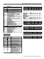
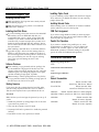
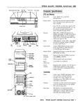
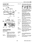
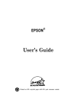
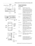
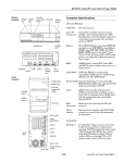
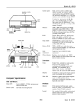
NEW EPSON ActionPC 5000, ActionTower 5000
speed light
power light
hard
hard disk
drive bays
reset button
Computer Specifications
CPU and Memory
32-bit CPU
486SX/25 or /33; SX2/50 or /66;
DX/33, /40, or /50; DX2/50 or /66;
DX4/75 or /100; or Pentium™OverDrive™
processor
Green PC
Energy Star compliant, low-power,
standby mode for the hard disk drive and
video signals sent by the computer to the
monitor; select timeout periods in SETUP;
in a standard configuration of one hard
disk drive and one diskette drive, system
consumes less than 30 watts in standby
mode
energy saver
I
diskette drive
button
/-\
System speed
inlet
AC outlet
MOUSE
COM2
Fast and slow processor speeds available;
fast is the speed of your processor and
slow is 8 MHz; 0 wait state memory access
at fast speed
Press Ctrl Alt and - to select slow speed or
Ctrl Alt and + to select fast speed
VGA
power light
power
speed light
hard disk
access light
Memory
4MB or 8MB RAM standard on a SIMM;
expandable to 64MB using 1MB, 2MB,
4MB, 8MB, 16MB, and 32MB SIMMs;
SIMMs must be tin-plated, 72-pin, 32-bit
or 36-bit, fast-page mode type with an
access speed of 70ns or faster
ROM
128KB Phoenix@ system BIOS, video BIOS,
and SETUP program located in EPROM
on main system board
Video RAM
1MB DRAM on main system board;
expandable to 2MB using eight,
4 x 4 x 256, 20-pin DIP chips
Shadow RAM
Supports shadowing of system and video
BIOS ROM into RAM
Memory
relocation
Supports relocation of 256KB of memory
from A0000h to BFFFFh and D0000h to
EFFFFh to extended memory
drive bays
PARALLEL
COM1
MOUSE
Km
option skits
AC Inlet
A C & l e t \ voltage switch
8/94
NEW EPSON ActionPC 5000, ActionTower 5000 - 1
NEW EPSON ActionPC 5000, ActionTower 5000
Cache
8KB of internal cache; supports 64KB,
128KB, or 256KB of external cache using
28-pin, 8 x 8 or 32 x 8, 20ns DIP chips; in
486DX/50 or Pentium OverDrive systems,
use a 15ns tag chip.
Math
coprocessor
Math coprocessor built into the
microprocessor for DX, DX2, DX4, and
Pentium OverDrive systems
Clock/
calendar
Option slots
Connector card with five full-length,
16-bit, I/O expansion slots; ISA
compatible; two of the full-length slots are
also VESA local bus compatible
Controllers
Cirrus Logic GD5428 high-speed, super
VGA local bus controller with True Color”
support; provides resolutions up to
1280 x 1024 in 256 colors; True Color
support in the 640 x 480 resolution
Diskette
Controller on main system board supports
up to two diskette drives or one diskette
drive and a tape drive
Hard disk
Internal
Mass Storage
ActionPC:
Energy Star compliant VGA interface for
fixed or multi-frequency monitor built into
system board; 15-pin, D-shell connector
Parallel
One standard, 8-bit, parallel,
unidirectional or bidirectional interface
built into main system board; 25-pin,
D-shell connector; operation controllable
by SETUP option
Serial
Two RS-232C, programmable,
asynchronous interfaces built into main
system board; 9-pin, D-shell connectors
Keyboard
PS/2 compatible keyboard interface built
into main system board; 6-pin, mini DIN
connector
Mouse
PS/2 compatible mouse interface built
into main system board; 6-pin mini DIN
connector
Front internal mount:
One 3*h-inch wide, half-height drive
Rear internal mounts:
Two 3%+inch wide, half-height drives or
one 31/1-inch wide, full-height drive
Externally accessible mounts:
Two 31&inch wide, third-height drives
and two 5’/4-inch wide, half-height drives
Optional 10-pin game port interface on
system board; can control joy-stick
functions with the addition of a port
connector
2 - NEW EPSON ActionPC 5000, ActionTower 5000
Internal mount:
One 3%~inch wide, one-inch high drive
Externally accessible mounts:
One 3 &nch wide, one-inch high drive
and two 5%+inch wide, half-height drives
ActionTower:
Interfaces
Optional game
port
Speaker
Energy Star compliant, high-speed, 32-bit
local bus IDE interface on main system
board supports up to two IDE hard disk
drives with built-in controller; BIOS
provides hard disk auto-sensing function
Monitor
Connector card with five 16-bit, ISA
compatible expansion slots; three
full-length and two half-length; two of the
full-length slots are also VESA local bus
compatible
ActionTower:
Contained in the 82C491 system controller
chip along with 64 bytes of CMOS RAM,
backed up by a soldered NiCad
rechargeable battery
Video
Action PC:
8/94
Diskette drive
types
3.5-inch diskette drive, 720KB or 1.44MB
storage capacity; 5.25-inch diskette drive,
360KB or 1.2MB storage capacity; or
combination 3.5-inch/5.25-inch diskette
drive
Hard disk drive
types
5!&inch or 3lh-inch form factor hard disk
drive(s), up to half-height size; maximum
of two drives
Other devices
Half-height tape drive, CD-ROM drive,
optical drive, or other storage device;
5%nch, or 3%nch with mounting frames
Keyboard
Detachable, two-position height; 101 or
102 sculpted keys; country-dependent
main typewriter keyboard; numeric/
cursor control keypad; four-key cursor
control keypad; 12 function keys
Mouse
Detachable, two-button, PS/2 compatible
NEW EPSON ActionPC 5000, ActionTower 5000
SETUP
Program
Stored in ROM; accessible by pressing F2
during boot
Major Subassemblies
System security
User and Supervisor level passwords
(8 characters) available for system boot or
diskette access
The following diagrams illustrate the major subassemblies in
the ActionPC 5000 and ActionTower 5000 systems.
ActionPC
Virus protection Write protection feature for the hard disk
drive boot sector; periodic reminder
message for running virus detection utility
option card
connector
board
Physical Characteristics
Dimension
Width
Depth
Height
1 Weight
ActionPC
16.8 inches (427 mm)
15.8 inches (401 mm)
4.4 inches (112 mm)
1 17.4 pounds (7.9 kg)*
ActionTower
7.125 inches (181 mm)
16.25 inches (413 mm)
13.25 inches (337 mm)
1 16.7 pounds (7.6 kg)*
power
supply
I
sockets
1
* With one diskette drive, without keyboard
tag RAM
Power Supply
Type
Input ranges
SIMM
sockets
I
external
cache sockets
200 Watt, UL/TUV/CSA listed, fan-cooled
90-130 VAC or 180-260 VAC;
switch-selectable
Maximum
outputs
+5 VDC at 20 Amps, -5 VDC at 0.5 Amps
+12 VDC at 8 Amps, -12 VDC at 0.5 Amps
Frequency
47 to 63Hz
Cables
Two to main system board, five to mass
storage devices; for more than five
devices, Y cables can be installed on the
existing cables
H
*
0
VESA
connector J
r
1
microprocessor
-
drive mounting
bracket
drive bays
ActionTower
Option slot power limits
external
cache sockets
\
-5 volts
+12 volts
-12 votts
Output Voltage (MC) I +5 Volts
For all slots
I 12 A m p s I0.4~mp I4.0~mps I0.4Amp
video
memory
s o c k e t s
Environmental Requirements
Non-operating
Operating range range
41° to 90°F
-4° to 140°F
1 (5° to 32° C)
1 (-20° to 60° C)
1 Humidity
I 20% to 90%
I 10% to 90%
1 (non-condensing) I
1 Altitude
Condition
Temperature
Storage range
-4° to 140°F
1 (-20° to 60° C)
1
10% to 90% I
Maximum wet bulb
drive bays
8/94
SIMM sockets
power
supply
NEW EPSON ActionPC 5000, ActionTower 5000 - 3
NEW EPSON ActionPC 5000, ActionTower 5000
System Board Components
The diagram below illustrates the components on the ActionPC 5000/ActionTower 5000 system board. The table following it
describes these components.
nrnnnnnnn
I
I
I
I
I
U49
I
mm CN16
9 mmcmn
CN18
4 - NEW EPSON ActionPC 5000, ActionTower 5000
8/94
NEW EPSON ActionPC 5000, ActionTower 5000
External cache jumper settings
components
Socket
I component
Cache size*
J24
J25
J26
J27
J28
U1, U2, U4,
U6
U5
U12, U13
I SIMM sockets
64KB
128KB
256KB
On
On
On
Off
On
On
Off
Off
On
1-2
2-3
1-2
Off
2-3
1-2
U15
U17
Keyboard/mouse controller
Super I/O controller (UMC82C863,865); supports up to two
diskette drives. two serial pods, and one parallel port
Microprocessor (ZIF socket)
Clock generator: 4V to 7V operating supply range, 1 ns skew.
l
*If you have no external cache installed, the position of these jumpers does not
matter.
Processor clock jumper settings
DX2/66, DX4/100, or
Cirrus Logic video controller (GD5428); local bus VGA with
C, dual-frequency synthesizer, BltBLT
l
Change these jumpers only if you upgrade your processor.
Processor type jumper settings
Processor*
J8
J9
J10
486SX/SX2
487SX/Pentium OverDrive
486DX/DX2/DX4
2-3
1-2,3-4
1-2,34
Open
2-3
1-2
Open
Open
Open
* Change these jumpers only If you upgrade your processor.
CN11
1 header
1 Serial port labeled COM2: 9-pin. D-shell
Processor voltage jumper settings
Processor voltage
J29
J32
1-2 and 3-4
(not used for 5-Volt processor)
5 volt
1-2
3.3 and 3.45 Volt
5-6 and 7-8
3-4
5-6 and 7-8
3.6 Volt
Note: To determine the voltage of your processor, see page 6.
SVGA jumper settings
Jumper Settings
J3
J4
J5
J6
J15
J19
Jumper
setting
1-2*
1 2-3
1-2*
2-3
1-2*
2-3
1-2*
2-3
1-2*
2-3
on*
Off
lOff*
J20
J21
Enable on-hoard VGA
Disable on-board VGA
On
Off
On
off
Jumper function
J1
J7
Enable PS/2 mouse support
Disable PS/2 mouse support
2-3
1-2
2-3
1-2
PS/2 mouse jumper settings
Miscellaneous jumper settings
Jumper
number
J2
VGA jumper function
Function
Assigns COM2 serial port as COM2
1 Assigns COM2 serial port as COM4
1 Assigns COM1 serial port as COM1
Assigns COM1 serial port as COM3
Assigns PARALLEL port as LPT1
Assigns PARALLEL port as LPT2
Enables optional game port
Disables optional game port
Enables diskette drive controller
Disables diskette drive controller
Selects VESA slot running at 1 waft states
Selects VESA slot running at 0 wait state
1 Disables IRQ9 for VGA
~
j 1-4
SETUP values to their factory defaults)
1 Selects external battery
8/94
NEW EPSON ActionPC 5000, ActionTower 5000 - 5
NEW EPSON ActionPC 5000, ActionTower 5000
SIMM Installation
Video resolutions, colors, and refresh rates
The computer comes with 4MB or 8MB of memory on a
SIMM. You can increase the memory in this computer up to
64MB by installing additional SIMMs. There are four SIMM
sockets on the main system board, and each can contain one
SIMM. You can install 1MB, 2MB, 4MB, 8MB, 16MB, and
32MB SIMMs.
Resolution
640X480
Memory
Requirements
Color
(MB)
1
1
1
256
32K/64K
16.8M (True
Refresh
rates (Hz)
Remarks
60/72
60
60
8 bits/pixel
16 bits/pixel
24 bits/pixel
The following table shows the possible SIMM configurations.
Do not install memory in any other configuration.
SIMM configurations
Non-interlaced and Interfaced
** Interfaced
l
External Cache
You can install 64KB, 128KB, or 256KB of external cache in
these systems. Use 8 x 8, 20ns DIP chips or 32 x 8, 20ns DIP
chips (15ns tag chip in 486DX/50 or Pentium OverDrive
systems) in the following configurations:
Cache memory configurations
BANK 0 (U44-47)
BANK 1 (U48-51)
8Kx8
8Kx8
32Kx8
(empty)
Tag SRAM (U43)
8Kx8
8Kx8
32Kx8
32Kx8
32Kx8
Total cache
64KB
128KB
256KB
Microprocessor Upgrades
The computer’s processor can be upgraded by replacing the
existing microprocessor with a faster one. You can either
purchase an upgrade kit from EPSON or buy the individual
components separately.
Microprocessor upgrade components
Video Memory
The computer comes with 1MB of onboard video memory,
expandable to 2MB using eight video DRAM, 256KB x 4 x 4,
20-pin, DIP chips. For the memory to work properly, you
must install one chip in each of the empty video memory
sockets (U34 through U41) on the system board.
4/75 processor
4/100 processor
1 Pentium OverDrive processor
1 Heat sink’
3.45 Volt
Intel
3.3 Volt
Intel
5 Volt
Intel
I Tennmax Trading Corp.
-
A heat sink is necessary for all DX, DX2, DX4. and Pentium OverDrive
processors.
6 - NEW EPSON ActionPC 5000, ActionTower 5000
8/94
NEW EPSON ActionPC 5000, ActionTower 5000
Hard Disk Drive Types
Drive Option Information
Your computer comes with a hard disk auto-sensing feature.
When you select the Autotype Fixed Disk option, the
system detects the type of hard disk drive you have installed
and fills in the drive information using values in the
following table.
IDE hard disk drive jumper settings
Hard disk drive types
l
CS (cable selection) can also be jumpered for any configuration. When CS is
used, the drive is a master if pin 28 is grounded or a slave if pin 28 is not
grounded.
Hard disk drive options for high-capacity, 1-inch IDE drives
l
Actual formatted size may be slightly different than size on drive label; you
cannot change this value.
Select 1 or none for the precomp value. If neither of these options are
available, select the maximum available precomp value.
8/94
NEW EPSON ActionPC 5000, ActionTower 5000 - 7
NEW EPSON ActionPC 5000, ActionTower 5000
Diskette and magnet-optical drive specifications
System Memory Map
FFFFFFFFFh
System BIOS ROM: 64KB
Duplicated from 0F0000h
FFFFF0000h
Resewed for system board: 64KB
Duplicated from 0E0000h
4000000h
64MB
(Maximum
system
memory)
Extended memory
001000000h
DMA Assignments
Level
DMA0
DMA1
DMA2
DMA3
DMA4
DMA5
DMA6
DMA7
System BIOS ROM: 64KB
Default Shadow RAM duplicated at FF0000h
Assigned device
Reserved (8-bit)
Reserved (8-bit)
FDD controller (8-bit)
Reserved (8-bit)
Cascade for DMA controller 1
Reserved (16-bit)
Resewed (16-bit)
Resewed (16-bit)
OOOFOOOOh
Unused or I/O expansion ROM: 160KB
Resewed for ROM on I/O adapters
000C8000h
000C0000h
VGA BIOS ROM: 32KB
Default Shadow RAM
VGA text
000B8000h
000B0000h
Hardware Interrupts
Video memory: 64KB
Resewed for graphics display buffer
640KB
000A0000h
Conventional system memory: 640KB
8 - NEW EPSON ActionPC 5000, ActionTower 5000
8/94
NEW EPSON ActionPC 5000, ActionTower 5000
System l/O Address Map
Connector Pin Assignments
-Hex address
000-01F
020 - 03F
022 - 024
034,03B,03C
040 - 05F
060-06F
070 - 07F (CMOS)
Parallel port connector pin assignments (CN12)
Assigned device
DMA controller 1,8237
interrupt controller 1,8259
UMC 82C481 chip set configuration register
AD12 chip set configuration registers
Timer, 8254
Keyboard controller, 8042
I Real-time clock NMI (non-maskable interrupt)
Pin
1
2
Signal
Strobe’
Data 0
Pin Signal
10
ACK *
11
Busy
Pin
19
20
Signal
Signal ground
Signal ground
1
8
9
IData
I Data 7
117
1 18
ISelectin*
I Signalground
I
1
* Active low logic
Serial port connector pin assignments (CN8 and CN11)
Keyboard and mouse connector pin assignments (CN5 and CN6)
Pin
1
2
3
Signal
Data
NC
Ground
Pin
4
5
6
Signal
VCC
Clock
NC
VGA port connector pin assignments (CN15)
Game port connector pin assignments (CN7)
Power supply connector pin assignments (CN1)
Pin
8/94
I Signal
[Pin
I Signal
NEW EPSON ActionPC 5000, ActionTower 5000 - 9
NEW EPSON ActionPC 5000, ActionTower 5000
Option card riser board connector pin assignment: (S1) (continued)
Diskette drive connector pin assignments (CN4)
Pin*
2
4
6
Signal
NC
NC
NC
Pin*
20
22
24
Signal
Step
Write data
Write enable
* Ail odd-numbered pins are grounds
Hard disk drive connector pin assignments (CN13)
‘Active low logic
VESA 112-pin expansion slot
13
14
ID2
ID13
127
1 IOCHRDY*
1
128
IBALE
I
*Active low ioglc
Speaker connector pin assignments (CN16)
Pin
1
2
Signal
+5VDC
NC
Pin
3
4
Signal
NC
Speaker data
LED connector pin assignments (CN10)
Pin
1
2
3
Signal
HDD LED (+)
Pin
4
Signal
Turbo LED (-)
HDD LED (-)
5
Turbo LED (+)
6
Power LED (+)
Power LED (-)
Option card riser board connector pin assignments (S1)
Pin Signal
A1
+12 VDC
A2 Ground
Pin Signal
A31 SA3
A32 SA2
Pin Signal
B1
+12 VDC
B2 +5VDC
Pin Signal
B31 BALE
B32 +5VDC
10 - NEW EPSON ActionPC 5000, ActionTower 5000
* Active low logic
8/94
NEW EPSON ActionPC 5000, ActionTower 5000
Option slot connector pin assignments
SA16
S415
S414
SA13
SA12
SA11
SA10
SA9
SA8
IA25 IS48
l
Active low logic
Tested Operating Environments
1 B19
1 C13 1 SD10
I
1
Although your system will run most software applications,
the following operating environments have been tested for
compatibility with your system.
*Active low logic
VL-bus slot connectors pin assignments
Microsoft MS-DOS 3.3 and later
Novell DR DOS
Novell NetWare* 2.2, 3.12, and 4.01
Novell NetWare Lite
IBM OS/2
SCO UNIX
SCO Open Desktop
Microsoft Windows 3.0 and later
Microsoft Windows for WorkGroups
Microsoft Windows NT
* The ActionTower is certified as workstation and file server;
the ActionPC is certified as a workstation.
The system has also been Novell tested and approved. As
new environments become available, these also will be tested.
l
Active low logic
8/94
NEW EPSON ActionPC 5000, ActionTower 5000 - 11
NEW EPSON ActionPC 5000, ActionTower 5000
Installation/Support Tips
Installing Diskette Drives
P Make sure that the drive type has been correctly selected
in the SETUP program.
Installing Option Cards
If you are installing a video adapter card that doesn’t support
VGA, make sure you disable the built-in VGA by removing
jumpers J20 and J21.
Installing External Cache
Cl Make sure jumper J6 is set to position 1-2 to enable the
diskette drive controller.
When installing cache on a 486DX/50 or Pentium OverDrive
system, make sure you use a 15ns tag chip.
Installing Hard Disk Drives
COM Port Assignment
If you are installing a drive that cannot use the embedded
IDE interface, such as an ESDI hard disk drive, it is
recommended that you use a 16-bit, AT-type hard disk
controller. If you install a non-IDE hard disk drive and
controller card, you must set jumper J23 to position 2-3 to
disable the built-in IDE hard disk drive interface. Also be
sure to remove the hard disk drive ribbon connector from
the system board.
When installing a hard disk drive, see the hard disk drive
type table on page 7 and use the auto-sensing feature in
SETUP to select the correct type number for the drive. If
the auto-sensing feature does not produce a match for the
drive, you can define your own drive type by selecting
User as the type and entering the drive’s exact
parameters.
If you want to assign COM1 as COM3, you must set jumper
J3 to position 2-3. If you want to assign COM2 as COM4, you
must set jumper J2 to position 2-3.
Parallel Port Operation
If you connect a scanner to the parallel port, set Auto
Configuration to Disabled so you can change the
Printer Port Control option to PS2 mode (for
bidirectional operation). The default setting for the parallel
port is AT mode (for unidirectional operation).
Software Problems
Cl When installing a copy-protected software package, first
try the installation at high speed. If this does not work
properly, select low speed by pressing Ctrl Alt - (using the
numeric keypad). Try loading the program at low speed
and then switching to high speed, if possible.
D When running a software package that uses a key disk as
its copy-protection method, try loading it at high speed. If
this does not work, load it at low speed.
Information Reference List
Engineering Change Notices
None.
Technical Information Bulletins
None.
Product Support Bulletins
None.
Related Documentation
TM-ACTPCT50
EPSON ActionPC 5000
ActionTower 5000 Service Manual
If you cannot boot the computer from the hard disk, make
sure the booting sequence in SETUP is set to A: then C : .
Then boot the computer from a system diskette in drive A.
PL-ACTPCT50
EPSON ActionPC 5000,
ActionTower 5000 Parts Price List
Password
400363500 EPSON ActionTower 5000 User’s Guide (English)
Make sure that you do not forget the password you set up. If
you do:
400363200
EPSON ActionPC 5000
Manual del usuario (Spanish)
1. Disable the password by setting jumper CN3 on the main
system board to position 3-4.
400363400
EPSON ActionTower 5000
Manual del usuario (Spanish)
Booting Sequence
2. Then turn the computer on and off again
3. Set jumper CN3 back to position 2-3 to enable the password
function.
4. Run SETUP to enter a new password, if desired.
12 - NEW EPSON ActionPC 5000, ActionTower 5000 8/94
400363300
EPSON ActionPC 5000 User’s Guide (English)