1
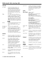
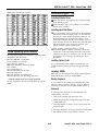
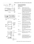
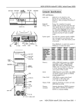
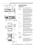
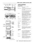
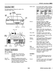
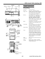
EPSON ActionPC 8000, ActionTower 8000
SPEED light
POWER light
hard disk
access light
(HDD)
RESET
drive bays button
Computer Specifications
CPU and Memory
I
POWER
button
diskette drive
POWER light
64-bit CPU
586-class processor
Green PC
energy saver
Energy Star compliant, low power
standby, doze, and suspend modes for the
CPU, hard disk drive, and VGA display;
select timeout periods, power-saving
rates, and other options in SETUP
Memory
64-bit DRAM interface supporting 8MB
RAM standard on two 4MB SIMMs;
expandable to 128MB using 1MB, 2MB,
4MB, 8MB, 16MB, 32MB, and 64MB
SlMMs; SIMMs must be tin-plated, 72-pin,
32-bit or 36-bit, fast-page mode type with
access speed of 70ns or faster
ROM
128KB Phoenix’s system BIOS, video BIOS,
and SETUP code in Flash ROM on main
system board
Video RAM
1MB video DRAM on main system board;
expandable to 2MB using two 512KB,
40-pin, SOJ flat pack video DRAM chips
Shadow RAM
Supports shadowing of system and video
BIOS ROM into RAM; video and option
ROM shadowing selectable in SETUP
Cache
Internal cache in the 586-class processor;
256KB, 512KB, or 1MB of external cache
installed on 32K x 8, 64K x 8, or 128K x 8,
3.3 volt, 15ns cache SRAM DIP chips and
two 32K x 8, 28-pin, 5 volt, 15ns tag chips
(one for the tag and one for the ALT bit);
internal and external cache controllable
through SETUP
Math
coprocessor
Math coprocessor built into the 586-class
processor
Clock/
calendar
Real-time clock, calendar, and CMOS
RAM socketed on main system board with
on-chip backup battery
SPEED light
access light
(HDD)
drive bays
printer (parallel
option
slots
AC inlet
- voltage selector switch
\
AC outlet
9/95
ActionPC 8000, ActionTower 8000 - 1
EPSON ActionPC 8000, ActionTower 8000
Controllers
PCI chipset
Video
Diskette
Hard disk and
other IDE
devices
Provides PCI caching, memory, and
control for the PCI bus and the twochannel PCI IDE interface (described
under ‘Hard disk and other IDE devices”
below); integrated PCI bridge translates
CPU bus cycles to PCI bus cycles and
CPU-to-PCI memory write cycles to PCI
burst cycles
Connector card with five I/O expansion
slots; three ISA compatible (8.33 MHz bus
speed) and two PCI compatible (33 MHz
bus speed); PCI slots support up to two
PCI bus masters
Speaker
Internal
Mass Storage
Slimline computer
Internal bays:
One 3.5-inch wide, one-inch high drive
S3™ Trio64™ PCI VGA controller with
integrated 24-bit RAMDAC, 64-bit DRAM
interface; includes power-saving and
multimedia features; supports resolutions
up to 1280 x 1024 in 16 colors with 1MB of
video RAM, increasing to 256 colors with
2MB of video RAM; True Color support in
the 640 x 480 resolution with 2MB of video
Externally accessible bays:
One 3.5-inch wide, one-inch high drive
and two 5.25-inch wide, half-height drives
Tower computer
Front internal bay:
One 3.5-inch wide, half-height drive
Rear internal bracket:
Two 3.5-inch wide, one-inch high drives
or one 35-inch wide, full-height drive
Controller on main system board supports
up to two diskette drives, or one
diskette/combo diskette and one tape
drive
Externally accessible bays:
Two 3.5-inch wide, one-inch high drives
and two 5.25-inch wide, half-height drives
Diskette drive
types
Two PCI, ATA-2 compatible, IDE
interfaces on main system board support
up to four IDE devices (two on each
interface); IDE CD-ROM drives cannot be
connected to the primary IDE interface or
to the same interface as IDE hard disk
drives; BIOS provides hard disk
auto-sensing and enhanced IDE functions
Interfaces
Monitor
Energy Star compliant video interface for
fixed or multi-frequency monitor built into
system board; 15-pin, D-shell connector
Parallel
One standard, multimode parallel
interface built into main system board;
supports 8-bit unidirectional, 16-bit
bidirectional, and ECP (Extended
Capability Port) modes; 25-pin, D-shell
connector; operation controllable by
SETUP program and jumpers
Serial
Option slots
Two high-speed RS-232C, programmable,
asynchronous interfaces built into main
system board; 16C550 compatible; 9-pin,
D-shell connectors; operation controllable
through SETUP
Keyboard
PS/2™ compatible keyboard interface built
into main system board; 6-pin, mini DIN
connector
Mouse
PS/2 compatible mouse interface built
into main system board; 6-pin mini DIN
connector
2 - ActionPC 8000, ActionTower 8000
3.5-inch diskette drive, 720KB or 1.44MB
storage capacity; 5.25-inch diskette drive,
360KB or 1.2MB storage capacity; or a
combination 3.5-inch/5.25-inch diskette
drive
Hard disk drive
types
5.25-inch or 3.5-inch form factor hard disk
drive(s), up to half-height size; maximum
of four drives
Other devices
Half-height tape drives, CD-ROM drives,
optical drives, PCMCIA card readers, or
other devices; 5.25-inch, or 3.5-inch with
mounting frames
Keyboard
Detachable, two-position height; 101, 102,
or 104 sculpted keys; country-dependent
main typewriter keyboard; numeric/
cursor control keypad; four-key cursor
control keypad; 12 function keys
Mouse
SETUP
Program
Detachable, two-button, PS/2 compatible
System security
Stored in ROM accessible by pressing Del
duringboot
User and Supervisor level passwords
available for system boot or diskette access
Virus protection Write protection feature for the hard disk
drive boot sector
9/95
EPSON ActionPC 8000, ActionTower 8000
Physical Characteristics
Dimension
Width
Jumper Settings
Slimline computer
Tower computer
16.8 inches (427 mm)
7.125 inches (181 mm)
Depth
15.8 lnches (401 mm)
16.25 Inches (413 mm)
Height
4.4 inches (112 mm)
13.25 inches (337 nun)
Weight
16.2 lb (8.3 kg) with one
diskette drive, but without
20.6 lb (9.3 kg) with one
diskette drive. but without
Miscellaneous jumper settings
Jumper Jumper
number setting Function
Fast-page mode video RAM
JP1
1-2 l
Power Supply
Type
200 Watt, UL/TUV/CSA listed, fan-cooled
Input ranges
90-130 VAC or 180-270 VAC; switchselectable
Maximum
output
+5 VDC at 20 Amps, -5 VDC at 0.5 Amp
+12 VDC at 8 Amps, -12 VDC at 0.5 Amp
Frequency
Cables
47 to 63Hz
Two to main system board, five to mass
storage devices; for more than five
devices, Y cables can be installed on the
existing cables
Option slot power limits
Output Voltage (VDC) 1 - 5 v o l t s
ll-w4 1 0.4 Amp
For all slots
1 +12 Volts
I-12 Volts
4.0 Amps
0.4 Amp
* Default setting
CPU clock jumper settings
Environmental Requirements
CPU clock speed*
50 MHz (for 75 MHz CPU)
60 MHz (for 90 MHz CPU)
100 MHz (for 100 MHz CPU)
JP16
pins 1-2
JP16
pins 3-4
Off
on
on
Off
on
on
* Default setting depends on speed of CPU
Parallel port ECP mode DMA channel (DRQ) settings
Jumper number
JP8
JP9
DRQ1 DMA channel
DRQ3 DMA channel
On pins 1-2
On pins 1-2
On pins 2-3
On pins 2-3
External cache size jumper settings
External cache size
256KB
512KB
1MB
9/95
JP10
Off
On
IOn
JP11
on
Off
on
ActionPC 8000, ActionTower 8000 - 3
EPSON ActionPC 8000, ActionTower 8000
System Board Components
The diagram below illustrates the components on the ActionPC 8000/ActionTower 8000 board.
The table following it describes these components.
/
1
JP2 -
diskette drive
/ Interface
.’
primary IDE
interface
JP8 JP9
4’
/
secondary IDE
/ interlace
Video RAM
sockets A
/
U13, U14
- JP12
JP10
JP11
- JP13
cache tag
socket
U20
El El
/
U29
U31
/
[I II II II JP17, JP18
l=a
rlrlmm
\
JP16
external cache
U33, 34, 35, 36
42, 43
U40, 41,
/ >-
lM3, SIM4
4 - ActionPC 8000, ActionTower 8000
speaker
\
JP21
9/95
EPSON ActionPC 8000, ActionTower 8000
The table below lists all the possible SIMM
not install SIMMs in any other configuration.
System board components
configurations;
do
SIMM configurations
J15
JP21
S1
HDD LED connector
1 Pins 2-3: Turbo LED connector
Pins 910: Hardware reset connector
Pins 11-13: Power LED connector
1 Pin 17-20: Speaker connector
1 Riser card slot; default settings of PCI AD Select care
Video Memory
U13, U14
U15, U16
U17, U22,
SIS 85C503, SIS85C501, CMD PCl0640B, and
I U33-U36,
U40-U43
U44
The computer comes with 1MB of video memory. You can
increase the video memory to 2MB by installing two 512KB,
40-pin, SOJ flat pack video DRAM chips.
Video DR
Soldered video RAM
Video resolutions and colors
I
Cache ALT bit chip socket
SIMM Installation
The computer comes with 8MB of RAM standard on two
4MB SIMMs. You can increase the memory up to 128MB
using pairs of 1MB, 2MB, 4MB, 8MB, 16MB, 32MB, or 64MB
SIMMs. The SIMMs must be tin-plated, 72-pin, single- or
double-sided, fast-page mode, parity or no-parity type with
an access speed of 70ns or faster. Be sure all the SIMMs
operate at the same speed.
* Non-interlaced and interlaced
** lnterlaced
9/95
ActionPC 8000, ActionTower 8000 - 5
EPSON ActionPC 8000, ActionTower 8000
External Cache
Hard Disk Drive Information
The computer has 256KB of external cache installed. You can
expand the external cache to 512KB or 1MB with 64K x 8 or
128K x 8, 3.3 volt, 15ns SRAM DIP chips.
The IDE hard disk drives listed in the tables below are
qualified for use in the computer.
IDE hard disk drive parameters
You must install chips in one of the configurations in the
table below (each bank contains four cache memory sockets).
Use only 3.3 volt cache SRAM chips made by Alliance
Semiconductor.
Cache memory configurations
Processor Upgrades
You can upgrade your processor with a faster one to improve
system performance. If you upgrade the processor in the
tower computer, you may want to lay the computer on its
side to make the installation process easier. If you are
upgrading to another processor, make sure you use a
standard 3.3 V processor.
Hard Disk Drive Types
The computer comes with a hard disk auto-sensing feature.
To use it, select one of the drives you have installed from the
Fixed Disk Setup screen On the screen that appears for that
drive, press Enter to select the Autotype Fixed Disk
option. The system detects the type of hard disk drive, fills in
the drive’s parameters, and sets the remaining options on the
screen.
6 - ActionPC 8000, ActionTower 8000
9/95
EPSON ActionPC 8000, ActionTower 8000
DMA Assignments
System I/O address map (Continued)
Hardware Interrupts
Wm.
IRQO
~Fuwt&n
1 Internal timer, PIT A counter 0 output
System Memory Map
Address range
FE0000h-FFFFFFh
100000h-FDFFFFh
0E0000h-0FFFFFh
08000h-0DFFFFh
0C0000h-0C7FFFh
0A0000h-0BFFFFh
000000h-09FFFFh
Function
128KB duplication of ROM BIOS stored at
0E0000h-0FFFFFh
System extended memory (128MB maximum)
128KB ROM BIOS
Adapter ROM BIOS
Video ROM BIOS
128KB Video memory
640KB base memory
System l/O Address Map
Connector Pin Assignments
Parallel port connector pin assignments (J1)
* Active LOW logic
Serial port connector pin assignments (J2 and J3)
Mouse and keyboard connector pin assignments (J6 and J7)
Pin Signal
1
Data
2
NC
3
Ground
Pin
4
5
6
Signal
VCC
Clock
NC
ActionPC 8000, ActionTower 8000 - 7
EPSON ActionPC 8000, ActionTower 8000
riser board connector pin assignment
VGA port connector pin assignments (J5)
HDD LED connector pin assignments (J15)
Pin (Signal
1
Red
IPin
ISignal
12
1 White
Power supply connector pin assignments (J10)
l
All odd-numbered pins are grounds
IDE drive connector pin assignments (J12 and J13)
*Active low logic
13
ID2
1 D13
14
*Active low logic
127
128
1 IOCHRDY*
IBAlE
1
I
8 - ActionPC 8000, ActionTower 8000
I
9/95
EPSON ActionPC 8000, ActionTower 8000
SIMM socket connector pin assignments
Installation/Support Tips
Installing Diskette Drives
0 Make sure that the drive type has been correctly selected
in the SETUP program.
0 Make sure jumper JP4 is set to position 1-2 to enable the
diskette drive controller.
Installing Hard Disk Drives
If you are installing a drive that cannot use the embedded
IDE interface (such as an ESDI drive), it is recommended
that you use a 16-bit, AT-type hard disk controller or, for
higher performance, a PCI hard disk controller. If you
install a non-IDE hard disk drive and controller card, you
must set jumper JP13 to on to disable the built-in IDE hard
disk drive interface. Also, remove the hard disk drive
ribbon connector from the system board.
*Active low logic
When installing an IDE hard disk drive, use the
auto-sensing feature in SETUP to select the correct type
for the drive. If the auto-sensing feature does not produce
a match for the drive, you can define your own drive type
by selecting User as the type and entering the drive’s
parameters.
Tested Operating Environments
The following operating environments have been tested for
compatibility with the system.
Microsoft MS-DOS 3.3 and later
Novell NetWare 3.12 and 4.1
Novell Personal NetWare
IBM OS/2; including version 3.0 (Warp)
SCO UNIX
SCO Open Desktop 3.1
Microsoft Windows 3.0 and later
Microsoft Windows 95
Microsoft Windows for WorkGroups
Microsoft Windows NT; including version 3.5
l
Installing Option Cards
If you are installing a video adapter card, make sure you
disable the built-in VGA controller by setting jumper JP2
to 2-3.
Installing SIMMs
Make sure you check jumpers JP12 and JP14 and change the
settings if necessary when you install SIMMs.
Booting Sequence
Certified as workstation end file server in certain configurations
As new environments become available, these also will be
If you cannot boot the computer from the hard disk, make
sure the booting sequence in SETUP is set to A: then C:.
Then boot the computer from a system diskette in drive A.
tested.
Password
If you forget your password, you must discharge your
CMOS memory as follows:
1. Turn off the computer and remove the cover.
2. Disable the password by setting jumper JP6 on the main
system board to on.
3. Turn the computer on, leave it on for a few seconds, then
turn it off again.
4. Set jumper JP6 back to off to select the system board battery.
5. Run SETUP to enter a new password, if desired.
9/95
ActionPC 8000, ActionTower 8000 - 9
EPSON ActionPC 8000, ActionTower 8000
Information Reference List
Engineering Change Notices
Technical Information Bulletins
None.
Product Support Bulletins
None.
Related Documentation
TM-ACTPCT80
EPSON ActionPC 8000,
ActionTower 8000 Service Manual
PL-ACTPCT80
EPSON ActionPC 8000,
ActionTower 8000 Parts Price List
400434500-1
EPSON ActionPC 8000,
ActionTower 8000 User’s Guide
10 - ActionPC 8000, ActionTower 8000
9/95