1
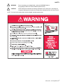
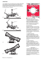
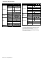
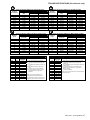
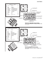
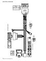
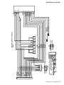
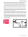
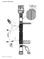
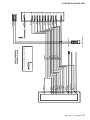
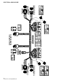
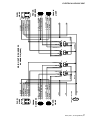
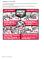
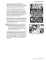
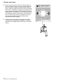
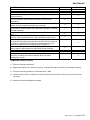
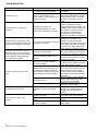
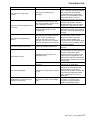
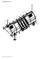
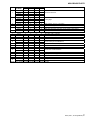
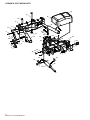
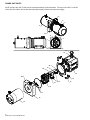
2005 Assembly & Operation Manual Models: 760LT, 760, 800 & 860 B 64059 10/4/05 INTRODUCTION/TABLE OF CONTENTS Congratulations on purchasing the finest straight blade snowplow available! Blizzard straight blades are clearing new trails for innovative design, rugged durability, quality craftsmanship and superior performance. Our exclusive products are manufactured and tested in Michigan’s Upper Peninsula, the snow capital of the Midwest. With an annual snowfall averaging over 250" we couldn’t imagine building snow removal products anywhere else! TABLE OF CONTENTS Safety .............................................. 3 Operation .......................................... 4 Unpacking & Inspection .................... 5 Technical Specifications ................... 6 Torque Specifications ....................... 7 Moldboard & A-Frame Assembly...... 9 Electrical-Plow Side .......................... 14 Electrical-Vehicle Side ...................... 18 Power Hitch™ Instructions ................ 24 Testing your Plow ............................. 25 Maintenance ..................................... 27 Troubleshooting ................................ 28 Moldboard Parts ............................... 30 A-Frame & Pivot Beam Parts............ 32 Power Unit Parts............................... 34 Manifold Parts................................... 36 Draw Latch, Controls & Lights Parts ................................... 38 Harnesses, Accessories & Kits......... 40 Warranty ........................................... 42 2 64059 (760LT, HD StraightBlade).doc SAFETY WARNING Prior to operating your straight blade, review the WARNING! label at the passenger’s side rear of the moldboard (shown below). CAUTION NOTE: Read and understand all warnings indicated in this manual prior t operating the snowplow. Warnings and cautions in the manual are indicated by the icons shown at left. NOTE: If at any time the safety labels become illegible, promptly replace them. 3 64059 (760LT, HD StraightBlade).doc OPERATION Your snowplow is the most advanced and versatile straight blade on the market. The easy-to-use joystick control allows you to automatically adjust the plow blade into an infinite number of plowing positions. Review the illustrations below for instruction on maneuvering your snowplow. A. A. Lowered or Float Position Pushing the joystick forward, toward the “Lower/Float” designation on the label, will lower your straight blade to the ground. Pushing and momentarily holding the joystick ahead will allow the snowplow to “float”, or follow the contour of the ground when moving forward or backward. B. B. Raised Position Pulling the joystick back, toward the “Raise” designation on the label, will lift your straight blade off of the ground. To stop raising the plow, simply return the joystick to its “neutral” or center position. The snowplow has reached its maximum raised position when the blade stops lifting – return the joystick to its neutral position. C. Angled Right Position To angle your straight blade to the right, position the joystick toward the “R” on the label. To stop angling the plow, return the joystick to its “neutral” or center position. The snowplow has reached its maximum angled position when the blade stops moving to the right side. C. D. 4 64059 (760LT, HD StraightBlade).doc D. Angled Left Position To angle your straight blade to the left, position the joystick toward the “L” on the label. To stop angling the plow, return the joystick to its “neutral” or center position. The snowplow has reached its maximum angled position when the blade stops moving to the left side. ***** IMPORTANT ***** To prevent premature failure of the power contactor (solenoid), initiate the plow function and return the joystick to its neutral or center position—except float. DO NOT hold the joystick in any position that allows the pump to continuously run after the plow has reached its maximum degree of movement. This will reduce the useful life of the solenoid. UNPACKING & INSPECTION Your Blizzard straight blade has been packaged to withstand transit and weather related damage. Fully inspect all components upon receipt of your plow. In the event of shipping damage or missing parts, immediately contact our Customer Service Department at 1-888-680-8600. Begin unpacking and inspection in the following order: 1. Remove the shipping document from the end panel of the pallet wrap. Retain all documentation for your records. 2. All wood framing and polyethylene material should be removed from the pallet for easy access to the snowplow. 3. Due to the odd shaped components and size of several assembly parts, various cable ties and corrugated material are used for scratch resistance and package orientation. Please remove these items prior to assembly. 4. Place the main blade assembly on a flat, level surface. Once you have inspected all parts and removed all packaging materials, your snowplow is ready to be fully assembled. Retain this information for your records. DATE OF PURCHASE: DEALER/DISTRIBUTOR: DEALER PHONE NUMBER: Pallet Wrap End Panel The tear-resistant, woven polyethylene pallet wrap contains a moisture barrier to help protect all packaged components and keep out the most inclement weather during shipping and storage. The end panel of the pallet cover contains important information regarding the snowplow model and the plow’s serial number. Both of these numbers are given together. The first three (four) digits of the number indicated is always the plow model – 810 (or 8611) and the entire number is the serial number (Ex: 810-00001 or 8611-00001). The shipping document is also attached to the end panel. Be sure to retain this list for your records. SNOWPLOW SERIAL NUMBER: HYDRAULIC PUMP SERIAL NUMBER: 5 64059 (760LT, HD StraightBlade).doc TECHNICAL SPECIFICATIONS PART SPECIFICATION Length Thickness Height Reinforcement MOLDBOARD Cutting Edge (1080) Finish Trip Mechanism Material A-FRAME Hitch Pins Finish Construction PUMP Type Size Motor Weight Mount MANIFOLD Reservoir Capacity Controls Construction Valves 760 LT 7’6” 760 800 860 7’6” 8’0” 12 gauge 31” 8’6” 29” 4 ribs @ 6 ribs @ 1/4" 3/16 " 3/8” 1/2” x 6” X 6” Powder Coat White (3) 3/8” hooked extension (4) 3/8” hooked extension Rectangular Tube & Channel Type 3/4” x 6” Yellow Zinc Powder Coat Black Steel Housing w/ Clear Plastic Tank Internal Gear Pump 2.5cc 12V Starter 32 lb. A-frame Install w/ hex head screws 2 qts. Toggle & Joystick Red Anodized Aluminum Electro-hydraulic cartridge PART SPECIFICATION 760 LT CYLINDERS PLOW HEADLIGHTS PLOW SPECS. 93/8” Ram Diameter Bore Diameter Raise/Lower Cylinders Stroke Ram Diameter Bore Diameter Type Measurements Housing Bulb Type Switch Type Weight (lbs)* Amperage Draw** (A) Adjustable Plow Shoes (2) Mount Mechanism Standard Control Station Optional Control Station 800 860 2 Angle Cylinders Stroke 760 10” 1-3/4” 2” 1 4-5/8” 1-1/4” 23” 1/2” Low profile w/ turn signals 12”W x 5”H x 5-1/4”D Plastic Composite High/Low Sealed Beam Halogen 12V Rectangular Dash Mount, Toggle 601 752 769 778 145 135 Std. Heavy-Duty Cast Steel Hydraulic Power Switch Joystick Touchpad *Plow weight does not include vehicle undercarriage. **Amperage draw specifications are based on the snowplow lift operation, at a shop temperature of 65°F, using Blizzard Snowplow Rapid Action Hydraulic Oil. Amperage will vary with temperature, oil viscosity and meter accuracy. Deadheading a plow function will result in significantly increased amperage. Blizzard Corporation reserves the right, under its Continuous Improvement Policy, to change construction or design details and furnish equipment when so altered without reference to illustrations or specifications. 6 64059 (760LT, HD StraightBlade).doc TORQUE SPECIFICATIONS (For reference only) Grade Identification Marking for J429-Grade 5 Bolt SAE J429 – Grade 5 Nominal Clamp Loads Tightening Torque Thread Size (lbs) “Lubricated” “Dry” 1/4-20 2,000 6 ft-lbs 8 ft-lbs 5/16-18 3,350 13 ft-lbs 18 ft-lbs 3/8-16 4,950 23 ft-lbs 31 ft-lbs 7/16-14 6,800 37 ft-lbs 50 ft-lbs 1/2-13 9,050 57 ft-lbs 75 ft-lbs 9/16-12 11,600 82 ft-lbs 109 ft-lbs 5/8-11 14,500 113 ft-lbs 151 ft-lbs 3/4-10 21,300 200 ft-lbs 266 ft-lbs 7/8-9 29,435 321 ft-lbs 430 ft-lbs 1-8 38,600 482 ft-lbs 640 ft-lbs Grade Identification Marking for Metric-Grade 8.8 Bolt Metric Class 8.8 Diameter Clamp Loads Tightening Torque (mm) (Pounds) “Lubricated” “Dry” 5 1,389 3 ft-lbs 5 ft-lbs 6 1,965 6 ft-lbs 8 ft-lbs 7 2,826 10 ft-lbs 13 ft-lbs 8 3,579 14 ft-lbs 19 ft-lbs 10 5,672 28 ft-lbs 37 ft-lbs 12 8,243 49 ft-lbs 65 ft-lbs 14 11,246 77 ft-lbs 103 ft-lbs 16 15,882 125 ft-lbs 167 ft-lbs 18 19,423 172 ft-lbs 229 ft-lbs 20 24,784 244 ft-lbs 325 ft-lbs Turns Size N/A N/A 2 2 1-1/2 1-1/2 1-1/2 1-1/4 1 1 1 1 1 -02 -03 -04 -05 -06 -08 -10 -12 -14 -16 -20 -24 -32 37° JIC Flare Torque Values Ft-lbs Assembly steps min.max 1. Make sure the tubing and threads are 6-7 clean. 8-9 2. Lubricate the threads with 10W hydraulic oil. 11-12 3. Hand tighten the nut/sleeve to approx. 30 14-15 in-lbs. 18-20 4. Make alignment marks on the nut and fitting. 36-39 5. Tighten to turn or torque specification. 57-63 6. When fully tightened, make a 2nd set of alignment marks at the fully tighten 79-88 positioned. 94-103 108-113 NOTE: Torque values specified are for threads lubricated with 10W hydraulic oil. 127-133 158-167 Over tightening will reduce the clamping force resulting in loss of seal and reduction of flow. 245-258 Grade Identification Marking for J429-Grade 8 Bolt SAE J429 – Grade 8 Nominal Tightening Torque Clamp Loads Thread Size (lbs) “Lubricated” “Dry” 1/4-20 2,850 9 ft-lbs 12 ft-lbs 5/16-18 4,700 18 ft-lbs 25 ft-lbs 3/8-16 6,950 32 ft-lbs 44 ft-lbs 7/16-14 9,600 53 ft-lbs 70 ft-lbs 1/2-13 12,800 80 ft-lbs 107 ft-lbs 9/16-12 16,400 115 ft-lbs 154 ft-lbs 5/8-11 20,300 159 ft-lbs 211 ft-lbs 3/4-10 30,100 282 ft-lbs 376 ft-lbs 7/8-9 41,550 454 ft-lbs 606 ft-lbs 1-8 54,540 680 ft-lbs 900 ft-lbs Grade Identification Marking for Metric-Grade 10.9 Bolt Metric Class 10.9 Diameter Tightening Torque Clamp Loads (mm) (Pounds) “Lubricated” “Dry” 5 1,987 5 ft-lbs 7 ft-lbs 6 2,812 8 ft-lbs 11 ft-lbs 7 4,044 14 ft-lbs 19 ft-lbs 8 5,121 20 ft-lbs 27 ft-lbs 10 8,116 40 ft-lbs 53 ft-lbs 12 11,796 70 ft-lbs 92 ft-lbs 14 16,092 111 ft-lbs 148 ft-lbs 16 21,970 173 ft-lbs 231 ft-lbs 18 26,868 238 ft-lbs 317 ft-lbs 20 34,284 338 ft-lbs 450 ft-lbs Size -02 -03 -04 -05 -06 -08 -10 -12 -14 -16 -20 -24 -32 O-Ring Boss Torque Values Ft-lbs Assembly steps min.max 1. Verify the port, o-ring, sealing surfaces and threads 6-7 are clean and free of damage. 8-10 2. Lubricate the threads and the o-ring with 10W hydraulic oil. 13-15 3. For an adjustable O.R.B., completely back off the lock 17-21 nut and washer. 22-25 4. Hand tighten the fitting until it contacts the port spotface. Point the elbow or tee in the desired 40-43 direction and hold. 43-57 5. Torque to specification. 68-75 NOTE: Torque values specified are for threads lubricated 90-99 with 10W hydraulic oil. 112-123 146-200 154-215 218-290 7 64059 (760LT, HD StraightBlade).doc NOTES 8 64059 (760LT, HD StraightBlade).doc MOLDBOARD & A-FRAME ASSEMBLY 1. Position the pivot beam and A-frame near the connecting points at the rear of the blade between the two center support ribs. Insert one 3/4" Dia. x 3" clevis pin through each mounting hole and secure with 1/4" Dia. x 1-1/2" cotter pin. NOTE: Mount the kickstand to the end of the pivot beam (driver’s side) using the 1/2"-13 x 4-1/2" bolt provided. The spring, bushing and lock nut are located on the inside of the pivot beam. Review the diagram to the right. To pivot the kickstand, pull the spring loaded leg out & rotate it until the pin locks into place. Adjust the foot on the stand arm so the height of the A-frame, at its mount points, is 12-1/2" to level ground. Tighten both of the top lock nuts on the kickstand. 12-1/2" NOTE: To prevent the kickstand from hitting the ground before the snowplow cutting edges, causing stress on the kickstand, adjust the kickstand foot approximately 1/8" short of level ground. This procedure will provide clearance for the kickstand when the snowplow is lowered with the kickstand in the down position. 2. Position each angle cylinder with the rod end of the cylinder in the pivot beam and the hydraulic hose port facing away from the A-frame. Secure with 3/4" Dia. x 5" clevis pin and 1/4" x 1-1/2" cotter pin. Extend each cylinder rod until the cylinder base mounting hole aligns with the hole on the Aframe angle cylinder bracket. Secure base with clevis pin and cotter pin. Spring Loaded Adjustable Pivot Beam Kickstand 3. Remove dust cap from both of the hydraulic angle cylinder ports and attach one 9/16"-18 x 9/16"-18 90° Adj. Elbow O.R.B. adapter to each port. NOTE: All of the hydraulic adapters can be found packaged with the manifold assembly, reference torque specifications. Each adapter should be angled toward the top of the moldboard. Connect the 3/8" x 24" hydraulic hose (60091) to the driver’s side angle cylinder adapter. Be careful not to over tighten the hose connections. Route both hoses over the TOP of each angle cylinder. This will prevent them from hanging or being pinched. 4. Remove the plastic dust caps from the lift cylinder ports. Attach one 9/16"-18 x 9/16"-18 45° Adj. Elbow O.R.B. adapter to the driver’s side port (base end) and one 9/16"-18 x 9/16"-18 male O.R.B. connector adapter to the passenger’s side port (rod end). Once the adapters have been installed on the cylinder, connect the hoses. NOTE: Position the fittings in the cylinder port such that the hoses install directly in the center of the A-frame access holes. A hose installed too close to the edge of the opening may work itself free with the operation of the lift cylinder and/or movement of the plow. Connect the 3/8" x 17" hose (60273) to the 45° adapter. Connect the 45° angle on the hose to the hydraulic adapter on the cylinder. The male connector adapter requires a 3/8" x 15" hydraulic hose (60274). Tighten the 45° end of the hose to the hydraulic adapter on the cylinder. Both hoses should be routed through the triangular openings in the A-frame. 1/8" Ground Clearance 9 16 9 16 9 16 9 16 60006 - Manifold Ports # 3, 4 60005 - Manifold Port #1 - Angle Cylinders 9 16 9 16 9 16 9 16 60007 fold Ports #3, 4 Lift Cyl. Rod 9 16 60272 - Lift Cyl. Base 9 16 60072 - Manifold Port 9 64059 (760LT, HD StraightBlade).doc MOLDBOARD & A-FRAME ASSEMBLY 5. Remove the draw latch mount pin, spacer & cotter pin from the draw latch assembly. By removing this pin, the inner draw latch plates can swing free. Remove the inner draw latch plate lift cyl. mount pin. Position the plates on either side of the lift/lower cylinder rod and insert the pin through the plates and cylinder rod. With the cylinder connected to the inner draw latch plates, rotate the draw latch assembly toward the draw latch mount holes on the A-frame. Align the holes in the outer draw latch plate with those of the inner draw latch plates and the Aframe. NOTE: The A-frame latch, located at the rear/center of the A-frame, should be raised up to insert the draw latch mount pin. Pull the Aframe latch pull pin out and rotate the latch counterclockwise if it is locked into position. Secure the assembly to the A-frame by replacing the draw latch mount pin, spacer and cotter pin. Reset the A-frame latch so the Aframe latch pull pin locks into place. 6. Assemble the manifold. The manifold, pump and coil harness have been connected at the factory; however, the manifold contains several components that you will need to install prior to securing the assembly to the A-frame. Each of the hose ports on the manifold are covered with stretch wrap. Remove the wrap and install the appropriate fitting in its respective port. NOTE: DO NOT let any foreign objects enter into the open ports. The valves can become contaminated and greatly hinder the plow’s performance. Torque to specifications. NOTE: All ports are identified by a stamped number on the manifold. The numbers also identify the hydraulic functions, which can be referenced on the label under the hydraulic pump and manifold cover. 10 64059 (760LT, HD StraightBlade).doc Hydraulic Lift / Lower Cylinder Draw Latch Mount Pin (1" DIA. x 4-21/32") or (1" DIA. x 3-7/8") for 760LT only A-Frame A-Frame Latch Latch Pull Pin Inner Draw Latch Plate Lift Cylinder Mount Pin (3/4" DIA. x 2-1/2") or (5/8" DIA. x 2-3/8") for 760LT only 3/16" x 2-1/2" Cotter Pin Inner Draw Latch Plate 1" O.D., 25/32" I.D. x 5/8" Spacer Outer Draw Latch Plate 3/16" x 2-1/2" Cotter Pin Draw Latch Arm Pivot Pin (3/4" DIA. x 2-1/2") or (3/4" DIA. x 2-3/8") for 760LT only Draw Pin (1" DIA. x 6-1/2") or (1" DIA. x 5-5/8") for 760LT only Clevis Pin (3/4" x 3-41/64") or (3/4" x 3-7/16") for 760LT only Hex Head Cap Screw (3/4"-10 x 4-1/2") or (3/4"-10 x 4") for 760LT only 2 1 1/4" x 1-1/2" Cotter Pin 3 4 NOTE: The arrows shown on the manifold illustration indicate the direction the 90° adapters should be positioned to receive the hydraulic hoses. MOLDBOARD & A-FRAME ASSEMBLY 7. Align the mount holes in the pump with the holes in the hinged bracket, located on the A-frame. NOTE: Before mounting the pump, angle the hinged bracket as needed and tighten the bracket hardware to lock it in place. Appl y Loctite CAUTION: When installing the manifold between the mount brackets on the A-frame, hold the manifold at the sides of the block. Never handle the manifold by coils. Doing so can cause a solenoid cartridge to bend, causing the cartridge to stick when activated. Secure with 3/8"-16 x 3/4" hex head cap screw and 3/8" flat washer through the top mount hole in the bracket and into the pump. Insert 3/8"-16 x 1-3/4" threaded stud with 3/8"-16 locknut through the bottom mount hole in the bracket and into the pump. The threaded stud should bottom out in the pump. NOTE: A medium strength thread locker, such as Loctite®242®should be used on both of the pump mount fasteners. 8. All of the hoses shipped with the snowplow contain a printed label (with a part number) applied to the hose. Install the following hoses to their respective ports on the manifold: Hose P/N 60091 Ports #1 & #2, Hose P/N 60273 Port #3 & Hose P/N 60274 Port #4. Install the driver’s side lift cylinder hose (60273). Attach the straight end of the hose to the 9/16"-18 90° swivel elbow adapter on the manifold. Connect the passenger’s side lower cylinder hose (60274) to Port #4. Loop the hose through the opening in the A-frame and connect the straight end of the hose to the 9/16"-18 90° swivel elbow adapter. Run both angle cylinder hoses (60091) over the A-frame angle and to their respective manifold ports. NOTE: The lift cylinder hoses should be routed through the triangular openings in the Aframe. Appl y Loctite ***** IMPORTANT ***** Use Loctite®242 on bolt connections illustrated above. 9. Secure the manifold to the A-frame. Remove the washers, split lock washers and capscrews from the manifold and align the mount holes with the A-frame brackets. Properly replace and tighten all hardware. NOTE: A medium strength thread locker, such as Loctite®242®should be used to secure the manifold mount fasteners. 10. Hook each extension spring to the receiving holes on the pivot beam and attach the opposite end of the spring to its respective spade bolts. Install the spade bolts through the extension spring mounting angle on the top rear of the blade. Secure each spade bolt with one 5/8" flat washer and one 5/8"-11 nylock nut. Tighten each nut until a piece of paper can pass between the 3rd & 4th coils on the spring. 11. Install the blade guides at each end of the moldboard. Insert the capscrew through the holes at the top of the wing reinforcement rib. Tighten all screws with lock nuts. 12. Install the plow harness. 11 64059 (760LT, HD StraightBlade).doc HYDRAULIC HOSE GUIDE 12 64059 (760LT, HD StraightBlade).doc SCHEMATIC A S5 B C S6 S8 D S 4 E S3 F G H J K S8 S6 S4 S3 S5 6 0 2 7 0 E L E C T R IC A L S C H E M A T IC 1 3000 PSI 2 3 RV 4 FC S5 S6 S3 S8 S4 TGP PGP T1 P1 6 0 2 7 0 H Y D R A U L IC S C H E M A T IC 13 64059 (760LT, HD StraightBlade).doc ELECTRICAL-PLOW SIDE INSTALLATION INSTRUCTIONS 1. Connect the red power wire from the plow harness to the pump motor terminal stud. Hardware provided on pump. 2. Place the 3/8 lock washer, the black ground wire(from the harness) and the red ground wire on the coil harness (from the manifold) over the tapped hole on the pump and secure with 3/8"-16 x3/4" screw. 3. Remove the nut and washer from the Power Hitch™ connect/disconnect toggle switch and insert it through the back of the mounting bracket on the A-frame. Align the notches on the switch and bracket. Replace the washer and nut and tighten until the switch is firmly in place. Attach the connector on the plow harness to the switch. NOTE: Use caution when connecting, switches can break if done forcefully. 4. Attach the connector on the harness to the connector on the coil harness. 5. Position the harness braid in the notch on the switch bracket and secure it with a cable tie. NOTE: The diode loop harness should be inside of the pump cover. 6. Install the pump & manifold cover by aligning the notches in the cover with the welded bolts on the A-frame brackets. Secure with clamping knob. Verify the cover is positioned over the protective toggle switch hood. Pop the front of the cover on the threaded stud and secure it with the remaining knob. 7. Install the vehicle harness. 14 64059 (760LT, HD StraightBlade).doc The Pump Cover Installs Over The Top Of The Draw Latch Switch Bracket ELECTRICAL BLIZZARD HARNESS PLUG (VEHICLE) UNIVERSAL 14 + 2 MOLD PIN NO. 1 2 3 4 5 6 7 8 9 10 11 12 13 14 15 16 COLOR BLACK BLACK RED BROWN/WHITE BROWN RED/WHITE RED/BLACK BLUE/WHITE BLUE/BLACK BLUE LT. GREEN WHITE ORANGE N/A N/A N/A PINK/BLACK N/A FUNCTION AWG GROUND GROUND 12 VOLT DC (+) PUMP SOLENOID TO RING PUMP SOLENOID TO MOLEX RIGHT SLIDE BOX EXTEND RIGHT SLIDE BOX RETRACT LEFT SLIDE BOX EXTEND LEFT SLIDE BOX RETRACT LEFT ANGLE RIGHT ANGLE LIFT FLOAT N/A N/A N/A 12 (+) VDC FUSED N/A 4 18 4 18 18 18 18 18 18 18 18 18 18 N/A N/A N/A 18 18 WIRE COLOR (BLUE) STRIPE COLOR (BLACK) 7 WIRE COLOR (RED) PIN NUMBER STRIPE COLOR (WHITE) 4 BLUE/WHITE PIN NUMBER EXAMPLE RED/BLACK BLUE/BLACK 8 BLUE 7 2 5 3 4 1 10 15 16 ORANGE BROWN 6 11 RED/WHITE BLACK TOP 14 3 9 1 13 BROWN/WHITE 12 LIGHT GREEN WHITE BLACK PINK/BLACK RED VEHICLE HARNESS PLUG (2005) FACE VIEW LOOKING AT FEMALE CONNECTOR FEMALE TERMINALS BLIZZARD HARNESS PLUG (PLOW) 1 2 3 4 5 6 7 8 9 10 11 12 13 14 15 16 COLOR FUNCTION AWG BLACK N/A RED BROWN RED/WHITE RED/BLACK BLUE/WHITE BLUE/BLACK BLUE LT. GREEN WHITE WHITE ORANGE N/A N/A N/A PINK/BLACK N/A GROUND N/A 12 VOLT DC (+) PUMP SOLENOID RIGHT SLIDE BOX EXTEND RIGHT SLIDE BOX RETRACT LEFT SLIDE BOX EXTEND LEFT SLIDE BOX RETRACT LEFT ANGLE RIGHT ANGLE LIFT LIFT FLOAT N/A N/A N/A 12 (+) VDC FUSED N/A 4 N/A 4 18 18 18 18 18 18 18 18 18 18 N/A N/A N/A 18 18 WIRE COLOR (PINK) STRIPE COLOR (BLACK) 15 Y PL AP IVE ITH Y W VE T L AL UC SE TI IC ND EA EN LL D V R O O E A RI -C C G PR N PE NON TRI N D O LS IO UN NA C S E I EL RO PO M DI OR OM TER C C PIN NO. WIRE COLOR (BLUE) PIN NUMBER STRIPE COLOR (WHITE) 6 RED/BLACK PIN NUMBER EXAMPLE BLUE/WHITE RED/WHITE BROWN LIGHT GREEN RED TOP 3 4 1 9 12 5 13 2 10 10 14 BLACK 7 6 15 8 11 16 BLUE/BLACK BLUE ORANGE WHITE (DOUBLE) PINK/BLACK PLOW HARNESS PLUG (2005) FACE VIEW LOOKING AT MALE CONNECTOR MALE TERMINALS 15 64059 (760LT, HD StraightBlade).doc 7 3 1 (1) (2) (3) (4) (5) (6) 5 6 BRN BRN ORG/RED WHITE PNK/BLK PNK/BLK 4 2 8 F G H J K BLU BLU/BLK BLU/WHT RED/BLK RED/WHT WHT WHT ORG/WHT ORG ORG/BLK ORG/RED DIODES (4) 6 AMP 600 VOLT ORG/BLK ORG/WHT WHT ORG/RED LT GRN C H ORG/BLK ORG/WHT B A ORG/RED ORG G F D J E K ORG/BLK ORG/WHT ORG/RED ORG PLOW HARNESS (62039) WHT 1 BLK 2 RED 3 BRN 4 RED / WHT 5 RED / BLK 6 BLU/ WHT 7 BLU/BLK 8 BLU 9 LT GRN 10 WHT 11 ORG 15 PNK / BLK 12 13 3 4 5 6 7 8 9 1 10 2 14 15 16 16 64059 (760LT, HD StraightBlade).doc 11 A B C D E ELECTRICAL-PLOW SIDE PERIODICALLY APPLY NON-CONDUCTIVE DIELECTRIC GREASE WITH CORROSION PREVENTIVE COMPOUND ON ALL TERMINALS BLIZZARD POWER PLOW TOP A K J H G F E D C B ORG/WHT D4 ORG/BLK ORG/WHT RED/WHT RED/BLK BLU/WHT BLU/BLK BLU LT GRN ORG/RED WHT ORG/WHT ORG/BLK ORG WHT D3 D1 WHT ORG/RED ORG/BLK ORG/RED ORG D2 ORG WHT ORG/WHT ORG/BLK ORG/RED PINK/BLK 6 PINK/BLK WHT 5 PLOW WIRE HARNESS SCHEMATIC (62039) ORG/RED ORG/RED ORG RED/WHT RED/BLK BLU/WHT BLU/BLK BLU LT GRN WHT 4 2 BRN ORG/BLK ORG/WHT ORG/RED WHT 3 1 BRN 4GA, BLACK 4GA, RED WHT BRN BLK RED RED/WHT RED/BLK BLU/WHT BLU/BLK BLU LT GRN WHT ORG PNK/BLK 1 2 4 5 6 7 8 9 10 11 15 3 ELECTRICAL-PLOW SIDE 17 64059 (760LT, HD StraightBlade).doc ELECTRICAL-VEHICLE SIDE CAUTION: Always attach the vehicle harness assembly with the vehicle off and the keys out of the ignition. Use caution when testing the electrical wires for the vehicle’s headlight functions. INSTALLATION INSTRUCTIONS 1. Insert the connector end of the harness through the driver’s side firewall access panel into the vehicle cab. Loosely position the remaining portion of the harness over the driver’s side fender well and place the plug end of the harness near the bumper. NOTE: Keep the plow plug and vehicle connector pins lubricated with a liberal amount of dielectric grease. Always replace the protective weather caps when the plow is disconnected from the vehicle. 2. Attach the power contactor (solenoid) to the driver’s side wheel well or engine fan guard using 12-14 x 3/4" self-drilling screws. NOTE: Some model vehicles provide mounting locations for accessory components. Always mount the solenoid with the terminals facing up, for extended solenoid life. Connect the 24" black ground wire to either small terminal on the solenoid and attach the opposite end to the vehicle with a selfdrilling screw. Cut the brown/white pump activation wire on the harness to length and crimp the eyelet terminal onto it. Attach the eyelet to the remaining small terminal on the contactor. Secure it with the hardware provided on the solenoid. 3. Connect the vehicle harness ground wire to the negative terminal on the vehicle’s battery. Cut the wire to length and crimp a 3/8" ring terminal on the wire. It is also recommended that the ring terminal be soldered. NOTE: The harness should be secured to the vehicle prior to taking the necessary measurement. Measure the distance needed for the power wire to reach the solenoid and properly secure an end ring terminal to it. Connect the power wire to either large terminal on the solenoid. CAUTION: Do not fasten the harness to areas that come in contact with moving engine parts or possess extreme heat. The harness could become tangled and/or melt causing electrical failure and vehicle damage. 4. Attach and solder an end ring terminal to both ends of the remaining length of the red wire. Connect one end of the wire to the open terminal on the solenoid and the remaining end to the positive terminal on the battery. 5. Position the main lighting harness with both of the truck light connectors near each truck headlight and the plow light connectors near the grill of the vehicle. 6. Plug the headlight ground/relay connector from the vehicle harness into the connector on the main lighting harness. Plug each headlight relay into the receptacles. Securely mount the receptacles to the vehicle with the terminal wires facing down and the relays facing up. Installing the relays in this position will allow moisture to drain from the relay. 7. Remove the front signal light assembly from both sides of the vehicle. Feed the violet, turn light wire, and gray, run light wire, from the main lighting harness through the opening in the signal light housing. Use a test light or ohm meter to determine the proper wires in the vehicle’s electrical system to splice into. Position one end of the turn or run light wire into the splice lock connector, and attach the vehicle wire into the opposite side. Complete the splice by pinching both wires together and locking the connector. Repeat the splice procedure for the remaining wire. 8. Connect the vehicle headlights to the main lighting harness using a light conversion harness kit. Due to differences in the construction of the kits, and the various make and model vehicles Blizzard snowplows are installed on, a light conversion kit is not packaged with your snowplow. Contact your local Blizzard dealer to obtain the appropriate conversion harness kit for your vehicle. 9. Secure the braided harness to the vehicle. Safely route all harness lengths around the engine components and attach them to the vehicle with cable ties. Extend the plow headlight connectors, from the main lighting harness, through the grill of the vehicle and position the harness power plug and weather cap near the bumper. Cable tie the plug to the vehicle bumper or tow hook to keep the harness from hanging too low. 18 64059 (760LT, HD StraightBlade).doc ELECTRICAL-VEHICLE SIDE 10. Install the remainder of the vehicle wire harness to the interior of the cab. Find an accessible location for the plow headlight toggle switch & bracket under the dashboard. Install the headlight bracket using two selfdrilling screws. Insert the toggle switch through the bracket and secure it with the hardware provided. Plug both of the switch leads into the toggle switch. NOTE: Both terminals should be inserted into the spades on the same side of the switch. One terminal should be positioned in the middle spade. Plug both 2-pin connectors together and this will connect the toggle switch to the vehicle wire harness. See diagram below. 11. Connect the power wire (with 15AMPFUSE) to a switched power source with a minimum of 15 amps. NOTE: The red power wire MUST be fused and switched on and off with ignition. Secure all loose wires under the dash. 12. Install the light tower. Position the arms into the receiving pockets located on the undercarriage. Each pocket has a lock pin that secures both light tower arms. Pull out and twist each handle to temporarily unlock the pins. Place the light tower into the pockets and relock the pins. See your local Blizzard dealer for complete installation instructions for your vehicle undercarriage. 13. Install the plow headlights. Align one headlight stud on the light tower tube with the mounting hole and insert the threaded stud through each. Secure the headlight with one 1/2" galvanized washer (neoprene facing up), one 7/16" external tooth lock washer and hex nut. NOTE: All snowplows are shipped with two caps that install on the ends of the light tower. Connect the terminals from the plow lights to the terminals on the main lighting harness. 14. Align the mount holes on the joystick control with the holes located on the mount pedestal. NOTE: The radius on the pedestal should face the dashboard. Secure the joystick to the pedestal with the 8-32 x 3/4" machine screws provided. Slide the Velcro® strap through the slots cut in the pedestal. The metal D-ring should be located on the side opposite of the radius. Wrap the strap around the bench and fasten. Connect the white power connector from the vehicle wire harness to the connector on the control station. The power switch should be in the “OFF” position. 15. Test your plow before using. TO CONTROL END VIEW LOOKING AT CONNECTOR VEHICLE HARNESS DPDT TOGGLE SWITCH GREEN/YELLOW 12" LONG GREEN/YELLOW 12" LONG .250 RECEPTACLES END VIEW LOOKING AT CONNECTOR 19 64059 (760LT, HD StraightBlade).doc 8 4 7 2 1 10 11 12 9 3 6 2 5 1 FUSE CAP FUSE BODY SPRING FUSE 15AMP 1 RED/WHT 2 RED/BLK 3 RED 4 ORG 5 BLU/WHT 6 BLU/BLK 7 BLK 8 WHT 9 BRN 10 PNK/BLK 11 LT GRN 12 BLU RED RED BRN/WHT GRN/YEL BLK 1 2 3 4 5 6 7 8 9 10 11 15 12 13 14 15 9 PNK/BLK 4GA RED BRN RED/WHT RED/BLK BLU/WHT BLU/BLK BLU LT GRN WHT ORG 4GA BLK 16 3 4 5 6 1 10 2 20 64059 (760LT, HD StraightBlade).doc 7 A 11 B 8 VEHICLE HARNESS (2005) ELECTRICAL-VEHICLE SIDE BLIZZARD POWER PLOW ORG WHT LT GRN BLU BLU/BLK BLU/WHT RED/BLK RED/WHT 11 10 9 8 7 6 5 4 1 2 4GA BLK 4GA 3 BLK RED BRN/WHT BRN PNK/BLK 15 BLACK BLK BRN RED/WHT RED/BLK BLU/WHT BLU/BLK BLU LT GRN WHT ORG PNK/BLK BLK B A GRN/YEL RELAY LIGHTING HARNESS NOTE: ALL GROUNDS HAVE BLACK WIRE VEHICLE HARNESS SCHEMATIC (2005) BLK BLK BRN RED/WHT RED/BLK BLU/WHT BLU/BLK BLU LT GRN WHT ORG PNK/BLK RED 1 2 GRN/YEL 7 9 1 2 5 6 12 11 8 4 10 3 ELECTRICAL-VEHICLE SIDE 21 64059 (760LT, HD StraightBlade).doc 22 64059 (760LT, HD StraightBlade).doc A 62016 WATER RESISTANT SPLICE LOCK CONNECTOR (USED IN INSTALLATION) OTHER WIRE OTHER WIRE VIOLET WIRE 62016 WATER RESISTANT SPLICE LOCK CONNECTOR (USED IN INSTALLATION) OTHER OTHER WIRE WIRE GRAY WIRE A = LOW BEAM (L GREEN/RED) B = COMMON (WHITE/RED) C = HIGH BEAM (YELLOW/RED) C B 30 85 B A B A 87 86 30 85 87a1 871 861 301 851 87a1 JACKET MATERIAL BLACK NYLON BRAID 86 C 87 D F 30 85 861 871 87a1 301 851 WHT BLK PNK GRY LT GRN/BLK YEL/BLK 87a A B C D E F E B A LT GRN/RED B WHT/RED C YEL/RED A LT GRN 86 30 87a 87 85 301 B1 87a1 861 871 861 871 87a1 301 851 YEL/BLK BLK/WHT YEL GRN/YEL YEL/RED LT GRN/BLK BLK/WHT LT GRN GRN/YEL LT GRN/RED 87 86 30 85 87a1 871 861 301 851 87a1 86 30 87a 87 85 301 B1 87a1 861 871 62016 WATER RESISTANT SPLICE LOCK CONNECTOR (USED IN INSTALLATION) OTHER OTHER WIRE PINK WIRE WIRE YEL/BLK BLK/WHT YEL GRN/YEL YEL/RED LT GRN/BLK BLK/WHT LT GRN GRN/YEL LT GRN/RED A C B 62016 WATER RESISTANT SPLICE LOCK CONNECTOR (USED IN INSTALLATION) OTHER OTHER WIRE GRAY WIRE WIRE A = LOW BEAM (L GREEN/RED) B = COMMON (WHITE/RED) C = HIGH BEAM (YELLOW/RED) A LT GRN/RED B WHT/RED C YEL/RED TRUCK LIGHT BULB C = HIGH BEAM (YELLOW) B = COMMON (WHITE/RED) A = LOW BEAM (L GREEN) A LT GRN C B A TRUCK LIGHT HARNESS C YEL 87a F E A B WHT/RED 87 D C A BLK B GRN/YEL B A C YEL 86 WHT BLK PNK GRY LT GRN/BLK YEL/BLK B WHT/RED TRUCK LIGHT BULB C = HIGH BEAM (YELLOW) B = COMMON (WHITE/RED) A = LOW BEAM (L GREEN) C B A TRUCK LIGHT HARNESS A B C D E F MAIN LIGHTING HARNESS (2005) ELECTRICAL-VEHICLE SIDE D F C E E LOW BEAM YEL/RED C VIO GRY LT GRN/RED WHT/RED BLK HIGH BEAM COMMON LOW BEAM LOW BEAM FEED A LT GRN A YEL/BLK PNK HIGH BEAM FEED COMMON B YEL WHT/RED C FROM VEHICLE HARNESS TRUCK LIGHT PARK-RUN D F HIGH BEAM GRY LT GRN/BLK RIGHT TURN C BLK Y E L /R E D YEL GRN/YEL BLK/WHT 86 87a 30 Y E L /B L K 85 87 L T G R N /R E D LT GRN 86 87a 30 L T G R N /B L K 85 87 Y E L /R E D 87a 30 MAIN LIGHTING HARNESS SCHEMATIC (2005) Y E L /B L K 87 GRN/YEL 87a LT GRN YEL WHT COMMON GROUND A B B TRUCK HARNESS B A B A L T G R N /R E D PLOW LIGHT 30 L T G R N /B L K BLK/WHT 87 RIGHT TURN D YEL/RED C PNK GRY LT GRN/RED WHT/RED TRUCK LIGHT HIGH BEAM COMMON LOW BEAM LOW BEAM FEED A LT GRN A F D TRUCK HARNESS E C HIGH BEAM FEED COMMON B YEL WHT/RED C YEL/BLK F HIGH BEAM B GRY LT GRN/BLK PARK-RUN E LOW BEAM B GROUND C A BLK A COMMON B PNK PLOW LIGHT WHT ELECTRICAL-VEHICLE SIDE 23 64059 (760LT, HD StraightBlade).doc POWER HITCH™ INSTRUCTIONS Prior to operating your straight blade snowplow, review the Mounting and Dismounting Instructions label on the back of the driver’s side moldboard. NOTE: If at any time the Mounting and Dismounting Instructions label, or any other label attached to your snowplow become illegible, promptly replace them. CONNECT/DISCONNECT Power Hitch Switch Adjustable Kickstand Undercarriage Push Beam CONNECT/DISCONNECT Power Hitch Switch A-Frame Latch A-Frame Latch Lock Pin Adjustable Kickstand Draw Pin 24 64059 (760LT, HD StraightBlade).doc Power Hitch TESTING YOUR PLOW 1. Fill the hydraulic pump reservoir with BLIZZARD SNOWPLOW RAPID ACTION HYDRAULIC OIL until it is approximately 3/4" from the top of the tank. Replace the cap on the reservoir. Remove the weather caps from each of the plow and vehicle harnesses and connect the plugs. 2. To raise the POWER HITCH on the snowplow, turn the power switch on the control station to the “UP” or “ON” position. Push and hold the toggle switch on the A-frame upward into the “CONNECT” position. Notice the action of the fluid in the reservoir. By activating the initial hydraulic function, the fluid begins to fill the system. Push and hold the toggle switch in the “DISCONNECT” position, the Power Hitch will lower. Refill the reservoir until the fluid is approximately 3/4" from the top of the tank. 3. Align the Power Hitch on the A-frame below the push beam, with the receiver plates in line with the receiver plates on the undercarriage. Pull out the A-frame latch pin and rotate the A-frame latch clockwise until the latch is resting on the draw pin. Move the snowplow in position by activating the Power Hitch connect switch and release. WARNING: Always use caution when operating the Power Hitch CONNECT/DISCONNECT switch. Keep your hands and feet away from the operation of the Power Hitch and the main blade. The action of the Power Hitch moves the snowplow in position for proper attachment to the vehicle. Failure to follow this caution may result in serious injury or death. The Power Hitch will rise until it hits the push beam and the draw latch fingers will pull the plow into the vehicle. The receiver plates on the plow and vehicle are now positively aligned. Rotate the A-frame latch counterclockwise until the latch is in the raised position. NOTE: The A-frame latch pin should always lock in place. Do not set the pin past the lock point on the A-frame. Insert the two hitch pins through the mounting holes on the A-frame and secure each with one hair pin cotter. Draw Latch in Transport Position 25 64059 (760LT, HD StraightBlade).doc TESTING YOUR PLOW 4. Return to the interior of the vehicle. The system power on the control station should be in the “ON” position. Raise the plow to its maximum height by pulling the joystick back (or down). Angle the snowplow to the left by moving the joystick toward the “L” (left angle) on the label. If the plow function is slow or delayed, the hydraulic fluid is filling the cylinder and replacing the air in the system. Test the remaining functions of the snowplow. Monitor the fluid level in the reservoir and fill to 3/4" from the top of the tank if needed. Also, look for any hydraulic fluid leaks around the manifold, pump, hydraulic hoses and all cylinders. 5. Check that the vehicle and plow headlights are in proper working condition including the turn signals. If necessary, adjust the plow headlight beams with the plow in the raised position. 26 64059 (760LT, HD StraightBlade).doc BLIZZARD ® WARNING To prevent accidental plow activation, turn POWER switch to the “OFF” position when not in use. BLZ 1017 MAINTENANCE MAINTENANCE Check fasteners for tightness. Torque to specifications. Check hoses for wear and leaks. Check cylinders for leaks; inspect rod ends for corrosion & pitting Lubricate all exposed cylinder rod ends with liquid white lithium grease to prevent corrosion. Check cutting edges and plow shoes for wear. NOTE: Do not discard plow shoe washers, these should be retained for different shoe adjustments. Clean and lubricate all electrical plugs and connections with dielectric grease. Clean and install all dust caps prior to storing. Lubricate all pins, bushings and A-frame latch with NLGI Grade 2 multipurpose lithium complex grease with molybdenum (MPGM) ) to maintain consistent operation Clean and paint all scratches or exposed metal with Blizzard touch-up paint Check the hydraulic oil level. Fill with fluid to 3/4” from the top of the reservoir. Do not exceed this level. Never mix different types of fluid. Remove and properly discard the fluid from the pump reservoir. Clean the pump filter and replace the hydraulic oil to within 3/4" from the top of the reservoir. Changing the fluid annually will prolong the life of your pump and manifold. Never mix different types of hydraulic oil. Check the trip spring adjustment. Properly adjusted tension will allow a sheet of paper to pass between the 3rd and 4th coils of the spring. Clean snow & ice build-up from the pump and manifold cover. Pressure wash and dry the entire snowplow prior to storing Cover the snowplow with a tarp if stored outside. This will protect your plow from sun fading and inclement weather which can lead to accelerated corrosion. PERIODICALLY X X X YEARLY X X X X X X X X X X X X X X REMOVING FROM STORAGE 1. Perform all regular maintenance. 2. Replace the hydraulic oil in the pump reservoir. Prolonged storage could result in condensation build-up. 3. Follow the mounting procedure on the Power Hitch™ label. 4. Initiate all of the functions. Monitor the fluid level in the reservoir and fill to 3/4” from the top of the tank as necessary. 5. Adjust the snowplow headlights as needed. 27 64059 (760LT, HD StraightBlade).doc TROUBLESHOOTING PROBLEM CAUSE Plow harness may not be properly connected to the vehicle harness. Pump will not run. Power or ground cables to the battery, pump or solenoid may not be properly connected. Pump will not run, power to the solenoid. The black ground wire and brown/white activation wire on the solenoid are not properly connected. Pump will not run with power to the solenoid. Brown/white activation wire and ground are properly connected. The red, hot wire to the pump motor is not properly connected. Pump will not turn off. Do not allow the pump motor to run continuously. Unplug the harness until the solenoid can be tested or a Blizzard Dealer can diagnose the problem. Solenoid may be damaged. Short in the joystick control or wire harness. Fluid level in the pump reservoir is low. Fluid is leaking. Pump runs but plow functions are slow. System pressure may be set too low. Increasing the pressure excessively will increase the amperage draw. This could damage the vehicle harness. Amperage from the vehicle’s alternator is too low. Pump filter may be clogged. A-frame latch will not move. Draw latch is binding the A-frame latch. Plow will not lift. Pump works properly. Control station in the cab may not be properly connected A-frame latch is in the (down) locked position. Diode loop harness may be corroded or could have failed. 28 64059 (760LT, HD StraightBlade).doc SOLUTION Verify the harnesses are properly connected. Properly connect all cables. Clean and lubricate with dielectric grease. If power does not resume, check the continuity of all cables to find the break. Properly connect both cables. Test for power by initiating any joystick function except the float. NOTE: The POWER rocker switch must be in the “ON” position to properly test any plow function. If the solenoid is grounded and no power exists, diagnose the plow & truck harnesses. Connect red wire and check the black ground wire. If problem is not resolved, the solenoid could be inoperable or the pump motor may be worn. Replace the solenoid if there is no power to the pump. Replace the pump motor if it is receiving power. Disconnect the brown/white activation wire from the solenoid. If the problem is not resolved, replace the solenoid. Disconnect the joystick in the cab. If the pump turns off, there is a short in the electrical system. Add fluid to within 3/4”from the top of the tank. Check for leaks around the pump, manifold and cylinders. Adjust the pressure. Remove the hex cap on top of the pump and turn the screw clockwise. Proper system pressure should be set at 2400PSI. Test functions and repeat procedure as needed. Repair or replace vehicle alternator. System amperage draw is 155A (175A for 8611) at 1500PSI. Remove the pump tank and thoroughly clean the filter. Lower the draw latch to relieve binding on the A-frame latch and reposition the A-frame latch as needed. Connect the power connector from the control to the vehicle harness. Lift the A-frame latch into the raised position. Clean diode loop harness thoroughly and/or replace. TROUBLESHOOTING PROBLEM Plow will not lift. Pump works properly. Plow will not lift with magnification to the S6 coil. CAUSE Coils on the manifold may be damaged. Hydraulic lock in the manifold. This occurs if the voltage is too low on the coils –should be 11.8 volts. Solenoid cartridge valve may be contaminated. Plow will not stay angled when plowing. The angle pressure relief valve is set too low. NOTE: Increasing the pressure relief valve will cause damage to your plow. Do not set the pressure relief greater than 3000 PSI. Plow will not angle, pump works. Review all probable causes above. Plow lowers too slow. Variable flow control valve is not adjusted properly. Review all probable causes for plow will not lift Plow drops sporadically. Variable flow control valve is opened too far. Headlights will not switch from the vehicle to the snowplow. No power or ground to the headlight relay. SOLUTION Remove the S6 coil from the cartridge valve. Position a screwdriver inside of the coil and push the draw latch connect/disconnect toggle switch upward. The screwdriver should be magnetically drawn to the coil. Replace the coil if there is no action. Loosen cartridge valve S6 to relieve pressure and retighten. DO NOT OVER TIGHTEN! Valves should be torqued to a maximum of 24 ft-lbs. Remove any foreign objects that may be obstructing proper valve operation. Replace if not operating properly after cleaning. Check the pressure relief by testing the valve inline with the cylinder. Attach a tee fitting to the angle cylinder hydraulic adapter and connect the hose and pressure gauge to the tee. NOTE: The setting should not exceed 3000PSI. NOTE: Verify coils S3 & S4 for angle functions. Turn flow control valve counterclockwise in small increments and test. NOTE: Never make adjustments when the plow is in the raised position! Fluid pressure will make the valve difficult to adjust and serious injury or death can occur from a falling plow. Verify S5 coil (float) or S5 & S8 coils (disconnect) for magnetism. Turn clockwise 1/16 of a turn and test. NOTE: Never make adjustments when the plow is in the raised position! Fluid pressure will make the valve difficult to adjust and serious injury or death can occur from a falling plow. Verify the headlight/ground relay connector is connected. If the connector is properly attached replace the headlight relay(s). 29 64059 (760LT, HD StraightBlade).doc MOLDBOARD PARTS 1 3 11 2 18 16 10 19 17 8A 9 4 8 12 13 14 7 15 6 5 5A 30 64059 (760LT, HD StraightBlade).doc MOLDBOARD PARTS REF PART NUMBER 81006 760LT 1 QUANTITY 760 800 - 860 - DESCRIPTION 84006 1 Moldboard Weldment 80006 1 80020 1 61165 1 61168 1 2 Cutting Edge 61164 1 61528 1 3 61196 8 8 8 8 Bolt, Carriage, 1/2"-13 x 1-1/2" Gr8 P 4 61365 8 8 8 8 Nut, 1/2"-13 Flanged Lock Z 61098 2 Plow Shoe Assembly, Standard (7-3/4" Shaft) Includes Ref 5-7 5A 61220 2 2 2 Plow Shoe Assembly, Heavy-Duty (8-3/8" Shaft) Includes Ref 5-7 5 61102 2 2 2 2 Spacer, 1-1/8" I.D., 1-5/8" O.D. x 1-1/2" YZ 6 61101 36 36 36 36 Washer, 1" Flat YZ 7 61103 2 2 2 2 Pin, Linch, 7/16" x 1-3/4" YZ 8A 61049 2 2 2 2 Plow Guide Assembly Includes Ref 8 & 9 8 61051 4 4 4 4 Screw, 5/16"-18 x 1" HHCS Gr5 Z 9 61052 4 4 4 4 Nut, 5/16"-18 Nylock Z 61176 1 1 10 Decal, Passenger’s Side Moldboard 61178 1 1 11 61181 1 1 1 1 Label, WARNING! (Blz1024) 12 63163 1 1 1 1 Decal, Center Moldboard 13 63167 1 1 1 1 Label, Power Hitch™ Mounting & Dismounting (Blz1077) 61177 1 1 14 Decal, Driver’s Side Moldboard 61179 1 1 15 63063 1 1 1 1 Label, Serial Number, Sequentially Numbered (Blz1049) 16 61188 3 4 4 4 Nut, Nylock, 5/8"-11 Type NE 17 61064 3 4 4 4 Washer, 5/8" SAE Hardened YZ 18 61201 3 4 4 4 Bolt, Spade, 5/8"-11 x 4-3/8" Grade 8 Z 61167 3 Spring, Extension, 12-15/16" O.A.L. x 2-3/8" O.D. x 3/8" 19 61099 4 4 4 Spring, Extension, 15-1/4" O.A.L. x 2-3/8" O.D. x 3/8" NOTE: Unless otherwise specified, quantities are the same for all models. 1 31 64059 (760LT, HD StraightBlade).doc A-FRAME & PIVOT BEAM PARTS 44 13 43 12 2 26 1 11 25 27 28 29 8 14 10 15 4 3A 30 31 32 35 24 9 16 7 42 34 17 5 6 33 3 38 37 36 39 40 21 23 20 22 19 32 64059 (760LT, HD StraightBlade).doc 18 41 A-FRAME & PIVOT BEAM PARTS QUANTITY PART DESCRIPTION NUMBER 760LT HD 83000 1 1 Pivot Beam Weldment 41041 1 2 61357 7 7 Pin, Cotter, 1/4" x 1-1/2" Z 3A 41039 1 1 Kickstand Assembly Includes Ref 3-10 3 41047 1 1 Kickstand Foot Weldment 4 41038 1 1 Kickstand Leg Weldment 5 61057 2 2 Screw, 1/2"-13 x 1-1/4" HHCS Gr8 YZ 6 61026 2 2 Washer, 1/2” Flat SAE Hardened 7 61020 3 3 Nut, 1/2"-13 Top Lock Z 8 61152 1 1 Screw, 1/2"-13 x 4-1/2" HHCS Gr8 YZ 9 61293 1 1 Spring, Compression, 2" O.A.L. x 1.101" O.D. x 0.207" Dia. 10 41037 1 1 Bushing, 1.13" O.D. x 0.53" I.D. x 3/8" Stepped 11 50069 2 2 Pin, 3/4"Dia. x 3" Clevis YZ 12 41051 4 4 Pin, 3/4"Dia. x 5" Clevis YZ 61331 1 Screw, 1"-8 x 8-1/2" HHCS Gr8 P 13 61330 1 Screw, 1"-8 x 9" HHCS Gr8 P 14 61008 1 1 Nut, 1"-8 Top Lock Z 60065 2 15 Hydraulic Cylinder, Plow Angle 60029 2 16 60091 2 2 Hydraulic Hose, 3/8" x 24" Plow Angle (Ports #1 ) 17 60005 3 3 Hydraulic Adapter, 9/16"-18 x 9/16"-18 90° Adjustable Elbow O.R.B. 60236 1 18 Hydraulic Cylinder, Plow Raise/Lower 60255 1 82061 1 Pin, 5/8" Dia. x 5-3/4”" Clevis YZ 19 40124 1 Pin, 3/4" Dia. x 6" Clevis YZ 20 60273 1 1 Hyd. Hose (Port #3), Straight/45°, 3/8" x 17" - Raise/Lower, Extend 21 60272 1 1 Hydraulic Adapter, 9/16"-18 x 9/16"-18 45° Adjustable Elbow O.R.B. 22 60007 3 3 Hydraulic Adapter, 9/16"-18 x 9/16"-18 Male O.R.B. 23 60274 1 1 Hyd. Hose (Port #4), Straight/45°, 3/8" x 15" - Raise/Lower, Retract 24 61628 3 3 Knob, 3/8-16 Nylock Clamping 25 61012 2 2 Screw, 3/8"-16 x 3/4" HHCS Gr8 YZ 26 61016 3 3 Washer, 3/8" SAE Hardened 27 61014 1 1 Nut, 3/8"-16 Jam Nylock Z, Type NTE 28 61629 1 1 Stud, 3/8"-16 x 2-1/8" Threaded 29 40004 1 1 Hinge Weldment, Pump Mount 30 61218 1 1 Screw, 3/8"-16 x 2" HHCS Gr8 YZ 31 61034 1 1 Nut, 3/8"-16 Top Lock Z 32 62038 1 1 Switch, Toggle, DPDT, (On)-Off-(On), 16 Amps, 115V AC 82043 1 33 A-frame Weldment 40091 1 34 61426 3 3 Pin, 3/4" x 6" Hitch YZ 35 61105 3 3 Pin, 9/64" DIA. x 2-11/16" Hair Cotter Z 36 40079 3 3 Pin, 3/8" DIA. x 1-3/4" SS 37 61000 3 3 Spring, 0.94" O.A.F.L. x 0.36" O.D., 0.029" Wire Dia. Compression SS 38 61309 3 3 Ring, Standard Split SS 39 61312 4 4 Screw, 5/16"-18 x 3/4" HHCS Gr8 YZ 40 61011 4 4 Washer, 5/16" Split Lock YZ High-Alloy 41 40088 2 2 Bushing, A-frame Pivot, Replaceable 42 61295 1 1 Label, Power Hitch Connect/Disconnect Switch (Blz1037) 43 40119 1 1 Cover, Hyd. Pump & Manifold 44 63099 1 1 Label, Hyd. Hose Identification Guide (BLZ1054) NOTE: Unless otherwise specified, parts for the 760, 800 & 860 Straight Blades listed as HD (Heavy Duty). REF 33 64059 (760LT, HD StraightBlade).doc POWER UNIT PARTS NOTE: Some of the 760LT’s will use the top pump assembly of this illustration. The rest of the 760LT’s and ALL of the 760, 800 & 860’s will use the bottom pump assembly. Please order parts accordingly. 8 2 3 4 1A 6 1 5 7 "THIS VIEW SHOWN WITHOUT RESERVOIR" 17 16 22 20 21 9 9A 15 19 12 11 18 10 34 64059 (760LT, HD StraightBlade).doc 13 14 POWER UNIT PARTS QUANTITY PART DESCRIPTION NUMBER 760LT HD 1A 60395 1 Power Unit-Pump Motor Tank Assembly (Monarch) Includes Ref 1-8 1 60396 1 Pump-0.138 in3/rev 2 60397 1 Reservoir-Ø4.5x8"Lg. 3 60398 1 Fill Cap/Breather-3/8NPT 4 60399 1 Motor-12VDC, 4.5", 1Terminal 5 60404 1 Tube-Suction, 90°, 3/8NPT 6 60405 1 Tube-Return, 90°, 1/8NPT 7 60406 1 Filter Screen Suction 8 60407 1 Clamp-Worm Gear 60400 1 Brush Kit-for 60399 Motor 9A 60402 1 1 Hydraulic Pump Assembly Includes Ref 9-10 & 12-22 (MTE) 9 60433 1 1 Reservoir 10 60434 1 1 Motor, 12VDC 11 60435 1 1 Seal Kit 12 60436 1 1 Pump Assembly, 1.47CC/REV 13 60437 2 2 Filter 14 60438 4 4 Clamp, Reservoir 15 60439 4 4 Reservoir, Screw 16 60345 1 1 Grommet 17 60346 1 1 Breather 18 60440 1 1 Relief Valve Asm. 19 60441 1 1 Tube, Plastic Suction 20 60442 1 1 Elbow 21 60443 1 1 Tube, Plastic Return 22 60444 1 1 Elbow 60445 1 1 Brush Kit-for 60434 Motor NOTE: Unless otherwise specified, parts for the 760, 800 & 860 Straight Blades listed as HD (Heavy Duty). REF 35 64059 (760LT, HD StraightBlade).doc MANIFOLD PARTS 22 11 23 10 7 9 7A 6 1A 8 4 1 5 15 12 13 18 14 19 20 17 21 3 16 2 36 64059 (760LT, HD StraightBlade).doc MANIFOLD PARTS REF PART NUMBER QTY DESCRIPTION 1A 60270 1 Manifold Assembly Includes Ref 1-7A, 8-10, 12-14, 16 & 17 1 60269 1 Manifold Block (with Cross Port Relief), Red Anodized Aluminum 2 60006 2 Hydraulic Adapter, 9/16"-18 90° Swivel Elbow 3 60072 1 Hydraulic Adapter, 9/16"-18 x 9/16"-18 Male Extra Long Elbow 4 60050 2 Plug, -6 SAE Hollow Hex 5 60173 1 Coupling, Test Port, 7/16"-20 O.R.B. 6 60167 2 Valve, Spool, Four-Way, Two Position C.C. 7A 62148 1 Coil Harness Assembly Includes Ref 7, 11 & 15, 62045, 62096, 62097, 62116 & 62117 62045 1 Connector, Electric, Male, Plastic 62096 15 Seal, Cable, Silicone, Orange (18 AWG) 62097 5 Terminal, Male (18-16 AWG) 62116 5 Silicone Cavity Plug, White (18-16 AWG) 62117 1 Terminal, End Ring, 3/8" I.D. Copper, 8 Gauge 7 62114 3 Coil, PDL 10V DC 8 60052 5 Nut, 1/2"-20 Hex Jam YZ 9 60168 1 Valve, Relief, 3000 PSI 10 60170 1 Valve, Spool, Three-Way, Two Position 11 62115 1 Coil, DDL 10V DC 12 60166 1 Valve, Spool, Three-Way, Two Position 13 61069 1 Valve, Flow Control 14 60165 1 Valve, N.C., Two-Way 15 62176 1 Coil, PDL 12V DC, Delta (waterproof, w/ O-rings) 16 60007 2 Hydraulic Adapter, 9/16"-18 x 9/16"-18 Male O.R.B. Connector 17 60005 1 Hydraulic Adapter, 9/16"-18 x 9/16"-18 90° Adjustable Elbow O.R.B. 18 60038 2 O-ring, 3/32" C.S.W. 9/16" I.D., 3/4" O.D. Neoprene, 70 Durometer 19 61016 2 Washer, 3/8" SAE Hardened 20 61222 2 Washer, 3/8" Split Lock YZ 21 61214 2 Screw, 3/8"-16 x 1-1/4" HHCS Gr8 YZ 22 61010 2 Screw, 5/16"-18 x 3-3/4" HHCS Gr8 YZ 23 61011 2 Washer, 5/16" Split Lock YZ NOTE: Unless otherwise specified, quantities are the same for all models. 37 64059 (760LT, HD StraightBlade).doc DRAW LATCH, CONTROLS & LIGHTS PARTS 18 17A 17 19 26A 20 26 27 24 25 21 22 34 28 29 30 23 12 6 1A 13 7 31 1 16 10/11 2 8 3 4 5 38 64059 (760LT, HD StraightBlade).doc 9 14 15 32 33 DRAW LATCH, CONTROLS & LIGHTS PARTS REF 1A 1 2 3 4 5 6 7 8 9 10 11 12 13 14 15 16 17A 17 18 19 20 21 22 23 24 25 26A 26 27 28 29 30 31 32 33 34 - PART NUMBER 82049 40109 82035 40080 82050 40110 61363 61200 61004 82055 50071 82014 40074 82027 40070 82054 40114 82058 40123 82033 40042 82024 40093 82036 40081 40116 61357 61006 61106 61107 61108 62032 62108 62061 62062 61231 61550 61112 61111 61427 39034 39032 62073 62074 63106 61185 61127 61254 61041 61088 61031 61174 62185 62186 62187 62188 62189 62190 QUANTITY 760LT 1 1 1 2 1 1 2 1 1 1 1 1 1 1 1 1 1 2 1 1 2 2 2 1 1 2 2 2 2 1 1 1 1 1 1 4 1 1 5 1 1 1 1 1 1 1 HD 1 1 1 2 1 1 2 1 1 1 2 1 1 1 1 1 2 1 1 2 2 2 1 1 2 2 2 2 1 1 1 1 1 1 4 1 1 5 1 1 1 1 1 1 1 DESCRIPTION Draw Latch Assembly Includes Ref 1-16 Outer Draw Latch Plate Weldment, Driver’s Side Pin, Draw, 1" Dia. x 5-5/8" (with 13/64" Dia. Cotter Pin Hole) BZ Pin, Draw, 1" Dia. x 6-1/2" (with 13/64" Dia. Cotter Pin Hole) YZ Pin, Cotter, 3/16" Dia. x 2-1/2" Z Screw, 3/4"-10 x 4" HHCS Gr8 YZ Screw, 3/4"-10 x 4-1/2" HHCS Gr8 YZ Pin, 3/4" Dia. x 3-7/16" Clevis YZ Pin, 3/4" Dia. x 3-41/64" Clevis YZ Inner Draw Latch Plate Pin, 1" x 3-7/8" Draw Latch Mount (To A-frame) YZ Pin, 1" x 4-21/32" Draw Latch Mount (To A-frame) YZ Draw Latch Arm Weldment Draw Latch Finger Weldment Pin, 5/8" x 2-3/8" Inner Draw Latch Plate/Hydraulic Cylinder Rod End Pin, 3/4" x 2-1/2", Draw Latch Arm Pivot Pin/Hydraulic Cylinder Rod End Pin, 3/4" x 2-3/8", Draw Latch Arm Pivot Bushing, 1-1/4" O.D. x 1-1/16" I.D. x 1-1/2" YZ Outer Draw Latch Plate Weldment, Passenger’s Side Spacer, 1" O.D. x 25/32" I.D. x 5/8" YZ Pin, Cotter, 1/4" x 1-1/2" Z Nut, 3/4"-10 Top Lock Z Headlight Assembly, Plow Includes Ref 17-23 & 62061 Headlight, Driver’s Side Headlight, Passenger’s Side Harness (with 6-pin plug), Plow Headlight Side Lighting Harness Repair Kit, Harness Side Bulb, Sealed Beam Halogen (H6545/H4666) Corrosion Preventive Compound (2fl.oz.) Adapter, Headlight Ball Stud Mount Washer, 1/2" I.D. x 1"O.D. Neoprene Backing Galvanized Washer, 7/16" Ext. Tooth Lock YZ Nut, 7/16"-14 Hex Gr8 YZ Cap, 2-1/4" I.D., 2-3/8" O.D. x 3/4", Black Vinyl Light Tower Control Station Assembly, Joystick Includes Ref 26, 27 & 34 Control Station, Joystick Label, Plow Power Switch, On/Off (Blz1061) Base Plate, Joystick Control Station 1/8" ABS Plastic Strap, (Velcro® with 2" Metal D-Ring) 61" Black Screw, 8-32 x 3/4" Pan Head Machine Z Bracket, Plow/Vehicle Headlight Toggle Switch Label, Plow/Vehicle Headlight Toggle Switch Bracket (Blz1008) Screw, 12-14 x 3/4" Hex Washer Self-Drilling Label, Control Station, Joystick (Blz1017) Switch-Rocker SPDT On-Off-On - Straight Blade Joystick Control Switch Switch-Straight Blade Joystick Functions Relay-Straight Blade Joystick Switch Actuator Kit-Handle Straight Blade Joystick (Includes Shaft, Sleeve, E-Ring). Mounting Plate 39 64059 (760LT, HD StraightBlade).doc HARNESSES, ACCESSORIES & KITS 2 4 1 3 1A 5. Help channel air flow to your truck radiator during the long haul over the road. Mounted front and center, our custom airfoil redirects air over the top of the blade and into the grill of your vehicle. The airfoil is shipped with complete mounting hardware. 8. Blizzard hydraulic oil is specially formulated for use in Blizzard snowplows and can significantly enhance the operation and performance of the hydraulic system. Blizzard zinc-free hydraulic oil maintains its viscosity to temperatures as low as 60°F.Blizzard oil is available by the quart, gallon, case or drum. 9. Our easy-to-install, adjustable pedestal mount will position your straight blade snowplow control station how you want it! Ideal for bucket seat vehicles with low center consoles. Pedestal accessory shipped with complete hardware and adapter plate. 12. Durable and long lasting, the polyurethane moldboard cutting edges will keep you plowing longer and safer! Specially formulated for snowplowing applications, Blizzard polyedges resist gouging, provide superior wear life and effectively reduce plowing noise. Ideal for all plowing conditions. Edges are shipped with mounting hardware. 40 64059 (760LT, HD StraightBlade).doc 6. Rugged and durable, the one piece 3/8"thick rubber design, 2-ply construction keeps snow off of your windshield and in its place—on the ground! The deflector is shipped with complete mounting hardware. 10. The straight blade snowplow touch pad control offers ergonomic comfort behind the wheel. Whether you hold it in your hand, strap it on your leg, wrap it around your seat or mount it to the dashboard, this control will provide the flexibility you need! Control is shipped with a molded plastic leg tray, adjustable Velcro® strap and extra Velcro® patches. Measures 3-1/4" x 3-1/4" x 1-5/16". 13. This adjustable bracket mounts easily to your straight blade joystick control and installs quickly onto any door panel. Ideal for left-hand joystick operation or for vehicles with center consoles. The window mount bracket is shipped complete with hardware. Some assembly required. 7. This kit includes the most common replacement parts: Angle cylinder hose, lift cylinder hose, hitch pin w/hair pin cotter, angle cylinder clevis pin w/cotter, 90° angle cylinder fitting, solenoid, Power Hitch™ toggle switch, corrosion preventive compound (2 oz.) and 10A fuse. The compact & durable plastic case (13.5"x9"x3.3") allows for easy storage behind or under your seat. 11. Get the response you demand from your plow with this easy-to install add-on and experience increased power and speed to all of the plow hydraulic functions! The auxiliary manifold bolts right up to the existing manifold and pump bracket without any modifications needed. Manifold provides up to 30 gpm input (4000 psi max.) from the vehicle pump and 2-3 gpm output (2500 psi max.). 14. Putting your snowplow away for the winter? Have a deep scratch to cover? Clean up your blade and plow parts with our gloss spray paints. Blizzard snowplow touch-up paint provides an excellent finish to help keep your snowplow looking its best. Paint provided in 12 oz. spray cans. HARNESSES, ACCESSORIES & KITS QUANTITY 760 800 1 1 1 1 1 1 1 1 10 10 REF PART NUMBER 760LT 1A 1 2 - 62039 62057 62001 62046 62093 1 1 1 1 10 - 61439 2 2 2 2 3 4 - 62167 62150 62000 62124 62212 62035 62144 62042 62178 62056 62072 62008 62009 62016 61031 81041 52093 61243 61242 61260 61545 63074 63070 63071 63072 63069 63091 63078 62142 60310 61544 61543 61542 61261 61219 63073 1 1 1 1 1 2 4 1 1 4 1 1 4 3 1 1 1 1 1 1 1 1 1 1 1 1 1 1 1 1 1 1 1 1 2 4 1 1 4 1 1 4 3 1 1 1 1 1 1 1 1 1 1 1 1 1 1 1 1 1 1 1 1 2 4 1 1 4 1 1 4 3 1 1 1 1 1 1 1 1 1 1 1 1 1 1 1 1 1 1 1 1 2 4 1 1 4 1 1 4 3 1 1 1 1 1 1 1 1 1 1 1 1 1 1 1 KITS - 61354 61353 1 - 1 1 1 - 60276 1 1 1 1 - 60281 61255 61256 61258 61259 61532 60360 60368 60371 62195 62196 1 1 1 1 1 1 1 1 1 1 1 1 1 1 1 1 1 1 1 1 1 1 1 1 1 1 1 1 5 6 7 8 9 10 11 12 13 14 860 1 1 1 1 10 DESCRIPTION Harness Assembly, Plow Includes Ref 1,2 & 62046, 62093, 61439, 62167 Harness, Plow Weather Cap, Rubber, Plow Side Connector, Electric, Female, Plastic Terminal, Female (18-16AWG) Cable Tie, Black, 15" Nominal Length Heavy Duty - 120psi Min Tensile - .3" Wide Harness, Diode Loop Harness, Vehicle Weather Cap, Rubber, Vehicle Side Fuse, 1/4" Dia. x 1-1/4" BUSS ARC 15A, 32V Harness, Main Lighting Weather Cap, Rubber, Lighting Harness Headlight Relay, CB1-D-12V, Power Contactor (Solenoid), 12 v Continuous Power Contactor (Solenoid), 12VDC-225A Ground Wire, Power Contactor, 24" Terminal, End Ring, 3/8" I.D. Copper, 4 Gauge Fuse Clip, Mini Fuse Clip, Auto Blade Connector, Splice Lock (18-14 WAG) Screw, 12-14 x 3/4"Hex Washer Self-Drilling Snowplow Airfoil Rubber Snow Deflector w/ hardware Emergency Parts Kit Blizzard Rapid Action Hydraulic Oil-Quart Case (12 quarts) Gallon Case (4 gallons) Drum (55 gallons) 12” Adjustable Pedestal Mount Touch Pad Control Station Central Hydraulic Valve Block Polyurethane Moldboard Cutting Edges (with Hardware) Straight Blade Joystick Window Mount Bracket Blizzard Power Plow High Performance 12 Oz. Spray Paint, Gloss White Blizzard Power Plow High Performance 12 Oz. Spray Paint, Gloss Black Kit, Hardware, Snowplow Assembly Parts Kit, Hydraulic Adapter Includes 60005 (3), 60006 (2), 60007 (3), 60072 (1) & 60272 (1) Kit, Hydraulic Hose Includes 60091 (2), 60273 (1), 60274 (1) Kit, Hardware, Moldboard Cutting Edge Kit, Cutting Edge, Moldboard w/Hardware Combo Seal Kit, Cyl 60029/60065 Combo Seal Kit, Cyl 60236 Combo Seal Kit, Cyl 60255 Kit, Headlamp 61106 (1-sealed beam, 1-rim , 4-spacer bumpers, 4-screws) Kit, Headlamp 61106 Signal (1-bulb, 1-turn signal lens, 1- gasket, 2-screws) 41 64059 (760LT, HD StraightBlade).doc LIMITED CONSUMER WARRANTY This warranty covers defects in material and workmanship except as set forth below. WARRANTED PARTY: This warranty applies only to the “Original Purchaser” who purchased this plow from an Authorized Blizzard Dealer, for personal, family or household use. TERM OF WARRANTY: This Blizzard snowplow is warranted for the following period: Parts and labor are warranted for one year from date of purchase. BLIZZARD CORPORATION’S WARRANTY REMEDY: Blizzard Corporation will, at its sole discretion, repair or replace defective parts at no charge. CUSTOMERS RESPONSIBILITY: To obtain warranty service, the purchaser must return the defective snowplow to any Authorized Blizzard Dealer. The purchaser must verify the original purchase date. Transportation costs to and from the dealer will be the responsibility of the purchaser. ITEMS NOT COVERED UNDER THIS WARRANTY: 1. Expendable parts such as cutting edges, plow shoes, hoses, fasteners, blade guides, paint finish, etc. 2. Any snowplow or part thereof which has been repaired or altered by anyone other than an Authorized Blizzard Dealer. 3. Any snowplow or part thereof which has been subject to neglect, misuse, accident, improper installation, maintenance, or storage. This includes, but is not limited to, corrosion of any electrical components. 4. Snowplows mounted on vehicles other than those for whom Blizzard Corporation has provided a specific mount system. 5. Blizzard Corporation does not assume liability for damage to the purchaser's vehicle resulting from the attachment and use of a Blizzard snowplow. Vehicle risk is the sole responsibility of the purchaser. WARRANTY LIMITATIONS: THIS WARRANTY IS OFFERED IN LIEU OF ANY OTHER EXPRESS WARRANTY. THE DURATION OF ALL IMPLIED WARRANTIES, INCLUDING BUT NOT LIMITED TO THE IMPLIED WARRANTIES OF MERCHANTABILITY AND FITNESS FOR A PARTICULAR PURPOSE, ARE LIMITED TO THE DURATION OF THIS WARRANTY. BLIZZARD CORPORATION'S LIABILITY IS EXPRESSLY LIMITED TO REPAIR OR REPLACEMENT OF DEFECTIVE PARTS. BLIZZARD CORPORATION SHALL NOT BE LIABLE FOR CONSEQUENTIAL, INCIDENTAL OR CONTINGENT DAMAGES WHATSOEVER, EVEN IF DAMAGES ARE CAUSED BY THE NEGLIGENCE OR FAULT OF BLIZZARD CORPORATION. State Laws: Some states do not allow exclusion of incidental or consequential damages or the limitations on how long an implied warranty lasts, so these limitations or exclusions may not apply to you. This warranty gives you specific legal rights and you may also have other rights which vary from state to state. This warranty does not apply if you purchased your snowplow for other than personal, family, or household use. If purchased for other than personal, family or household use, refer to the Blizzard Snowplow Commercial Warranty. 95 AIRPARK BOULEVARD CALUMET, MICHIGAN 49913 [906] 482-5555 1410-4-05 REV 4/05 COMMERCIAL WARRANTY This warranty covers defects in material and workmanship except as set forth below. WARRANTED PARTY: This warranty applies only to the “Original Purchaser” who purchased this plow from an Authorized Blizzard Dealer, for commercial use. TERM OF WARRANTY: This Blizzard snowplow is warranted for the following period: Parts and labor are warranted for one year from date of purchase. BLIZZARD CORPORATION’S WARRANTY REMEDY: Blizzard Corporation will, at its sole discretion, repair or replace defective parts at no charge. CUSTOMERS RESPONSIBILITY: To obtain warranty service, the purchaser must return the defective snowplow to any Authorized Blizzard Dealer within the warranty period. The purchaser must verify the original purchase date. Transportation costs to and from the Dealer will be the responsibility of the purchaser. ITEMS NOT COVERED UNDER THIS WARRANTY: 1. Expendable parts such as cutting edges, plow shoes, hoses, fasteners, blade guides, paint finish, etc. 2. Any snowplow or part thereof which has been repaired or altered by anyone other than an Authorized Blizzard Dealer. 3. Any snowplow or part thereof which has been subject to neglect, misuse, accident, improper installation, maintenance, or storage. This includes, but is not limited to, corrosion of any electrical components. 4. Snowplows mounted on vehicles other than those for whom Blizzard Corporation has provided a specific mount system. 5. Blizzard Corporation does not assume liability for damage to the purchaser's vehicle resulting from the attachment and use of a Blizzard snowplow. Vehicle risk is the sole responsibility of the purchaser. LIMITS OF BLIZZARD CORPORATION’S LIABILITIES: BLIZZARD CORPORATION'S LIABILITY IS EXPRESSLY LIMITED TO REPAIR OR REPLACEMENT OF DEFECTIVE PARTS. BLIZZARD CORPORATION SHALL NOT BE LIABLE FOR CONSEQUENTIAL, INCIDENTAL OR CONTINGENT DAMAGES WHATSOEVER, EVEN IF DAMAGES ARE CAUSED BY THE NEGLIGENCE OR FAULT OF BLIZZARD CORPORATION. THE FOREGOING WARRANTIES ARE EXCLUSIVE AND IN LIEU OF ALL OTHER EXPRESSED AND IMPLIED WARRANTIES INCLUDING, BUT NOT LIMITED TO, THE IMPLIED WARRANTIES OF MERCHANTABILITY AND FITNESS FOR A PARTICULAR PURPOSE. This warranty does not apply if you purchased your snowplow for personal, family, or household use. In this case, refer to the Blizzard Snowplow Limited Consumer Warranty. 95 AIRPARK BOULEVARD CALUMET, MICHIGAN 49913 [906] 482-5555 1410-4-05 REV 4/05 760LT, 760, 800 & 860 STRAIGHT BLADES 95 Airpark Boulevard Calumet, MI 49913 [888] 680-8600 [906] 482-5555 [906] 482-5445 Fax www.blizzardplows.com Blizzard, Power Hitch and Seat Cinch are trademarks of Blizzard Corporation. Blizzard is registered in the United States Patent and Trademark Office. Loctite and 242 are registered trademarks of Loctite Corporation, USA. Velcro is a registered trademark of Velcro Industries B.V. All other trademarks and registered trademarks are the property of their respective owners. All Blizzard snowplows are protected by one or more of the following United States Patents: 5,638,618; 5,899,007; 6,178,669; 6,276,076; 6,393,737 and 6,615,513. Other patents pending. Copyright ©2005 Blizzard Corporation. All rights reserved. Made and printed in the USA. 64059