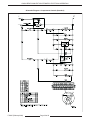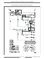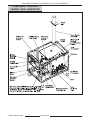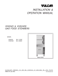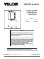
1
SERVICE MANUAL
C24GA SERIES
CONVECTION
STEAMERS
MODELS
C24GA6
ML-136021
C24GA10
ML-136022
- NOTICE This manual is prepared for the use of trained Vulcan Service
Technicians and should not be used by those not properly
qualified. If you have attended a Vulcan Service School for this
product, you may be qualified to perform all the procedures
described in this manual.
This manual is not intended to be all encompassing. If you have
not attended a Vulcan Service School for this product, you should
read, in its entirety, the repair procedure you wish to perform to
determine if you have the necessary tools, instruments and skills
required to perform the procedure. Procedures for which you do
not have the necessary tools, instruments and skills should be
performed by a trained Vulcan Service Technician.
Reproduction or other use of this Manual, without the express
written consent of Vulcan, is prohibited.
For additional information on Vulcan-Hart or to locate an authorized parts and
service provider in your area, visit our website at www.vulcanhart.com
VULCAN-HART
DIVISION OF ITW FOOD EQUIPMENT GROUP, LLC
WWW.VULCANHART.COM
3600 NORTH POINT BLVD.
BALTIMORE, MD 21222
F35425 (February 2006)
C24GA SERIES CONVECTION STEAMERS
TABLE OF CONTENTS
GENERAL................................................................................................................................................................
Introduction .......................................................................................................................................................
Installation ........................................................................................................................................................
Operation ..........................................................................................................................................................
Cleaning ..........................................................................................................................................................
Specifications ...................................................................................................................................................
Gas Line Pressures ..................................................................................................................................
Burner Pressure ........................................................................................................................................
Electrical ...................................................................................................................................................
Water Supply ............................................................................................................................................
Tools .................................................................................................................................................................
Standard ...................................................................................................................................................
Special ......................................................................................................................................................
4
4
4
4
4
4
4
4
4
4
4
4
4
REMOVAL AND REPLACEMENT OF PARTS .......................................................................................................... 5
Covers and Panels ............................................................................................................................................ 5
Cooking Compartment Right Side Panel.................................................................................................... 5
Cooking Compartment Flue Wrap ............................................................................................................. 5
Cooking Compartment Left Side Panel ...................................................................................................... 5
Cabinet Base Right Side Panel ................................................................................................................. 5
Cabinet Base Left Side Panel .................................................................................................................... 6
Cabinet Base Front Panel ......................................................................................................................... 6
Cabinet Base Rear Panel .......................................................................................................................... 6
Cooking Compartment Door .............................................................................................................................. 6
Door Assembly .......................................................................................................................................... 6
Door Gasket .............................................................................................................................................. 7
Door Handle .............................................................................................................................................. 7
Door Latch Assembly ................................................................................................................................ 8
Compartment Controls ...................................................................................................................................... 8
Main Burner ...................................................................................................................................................... 9
Gas Combination Control Valve ......................................................................................................................... 9
Generator Assembly ......................................................................................................................................... 9
Fill and Cold Water Solenoid Valves ................................................................................................................ 11
Pilot Spark/Probe Flame Sensor ..................................................................................................................... 12
SERVICE PROCEDURES AND ADJUSTMENTS ...................................................................................................
Blower Air Pressure Adjustment ......................................................................................................................
Air Pressure Switch Adjustment .....................................................................................................................
Pilot Burner Adjustment ..................................................................................................................................
Operating Pressure Switch ......................................................................................................................
Thumb Wheel Adjustment .......................................................................................................................
Inlet Water/Steam Strainer ......................................................................................................................
Automatic Ignition Systems ............................................................................................................................
Spark Ignition Control Test .......................................................................................................................
Ignition Test ....................................................................................................................................................
Manifold Pressure Adjustment ........................................................................................................................
Cooking Compartment ....................................................................................................................................
Controls ..................................................................................................................................................
Door ...............................................................................................................................................................
Latch Adjustment ....................................................................................................................................
Striker Adjustment ...................................................................................................................................
Deliming the Generator ...................................................................................................................................
Cooking Cycle Test .........................................................................................................................................
General ...................................................................................................................................................
Probe Inspection .............................................................................................................................................
F35425 (February 2006)
Page 2 of 40
13
13
13
14
15
16
16
17
17
18
18
19
19
19
19
20
20
21
21
21
C24GA SERIES CONVECTION STEAMERS
ELECTRICAL OPERATION ....................................................................................................................................
Water Level Controls ......................................................................................................................................
Low Level Cut-Off & Differential Control ....................................................................................................
Sequence of Operation ...................................................................................................................................
Initial Fill and Preheat Conditions ............................................................................................................
Schematics ....................................................................................................................................................
Component Location Cabinet Base Generator ................................................................................................
Component Function Cabinet Base Generator ................................................................................................
Component Location Cooking Compartment ...................................................................................................
Component Function Cooking Compartment ...................................................................................................
General ...................................................................................................................................................
22
22
22
22
22
25
28
29
31
32
32
TROUBLESHOOTING ............................................................................................................................................
General ...................................................................................................................................................
Water Not Being Supplied to Generator ...................................................................................................
Pilot Or Main Burner Will Not Light ..........................................................................................................
Drain Solenoid Valve Does Not Drain .......................................................................................................
Water Accumulating in Compartment ......................................................................................................
Cooking Cycle Cannot be Activated .........................................................................................................
Steamer Achieves Pressure Slower Than Normal ....................................................................................
Troubleshooting Sequence Of Operation .........................................................................................................
33
33
33
33
33
33
33
33
34
TROUBLESHOOTING CHART................................................................................................................................ 35
CONDENSED SPARE PARTS LIST ....................................................................................................................... 38
©VULCAN 2005
Page 3 of 40
F35425 (February 2006)
C24GA SERIES CONVECTION STEAMERS - GENERAL
GENERAL
INTRODUCTION
TOOLS
Procedures in this manual will apply to all models
unless specified. Pictures and illustrations can be of
any model unless the picture or illustration needs to
be model specific.
Standard
•
Standard set of hand tools.
•
VOM with A.C. current tester (Any quality VOM
with a sensitivity of at lease 20,000 ohms per volt
can be used.)
INSTALLATION
Refer to the Installation and Operation Manual for
detailed installation instructions on steamers.
OPERATION
Refer to the Installation and Operation Manual for
specific operating instructions.
Special
•
Gas leak detection equipment.
•
Gas Manometer.
•
Loctite 271
•
Screwdriver, 1/8 X 4 cabinet tip
CLEANING
Refer to the Installation and Operation Manual for
specific cleaning instructions.
SPECIFICATIONS
Gas Line Pressures
•
Operating Pressure
Natural - Recommended 2.5” W.C.
Propane - Recommended 10.0” W.C.
•
Incoming Pressure
Natural - Recommended 7.0” W.C. min.
Propane - Recommended 11.0” W.C. min.
Burner Air Pressure
0.4” W.C.
Electrical
Voltage: 120/60/1
Amps: 2.5 Amps
Frequency: 50/60 Hz
Water Supply
Supply pressure: 20-60 psig
Hardness*: Less than 3 grains
Silica: Less than 13 ppm
Total Chloride: Less than 4.0 ppm
pH Range: 7 to 8
Undissolved Solids: Less than 5 microns
(*17.1 ppm = 1 grain of hardness)
F35425 (February 2006)
Page 4 of 40
C24GA SERIES CONVECTION STEAMERS - REMOVAL AND REPLACEMENT OF PARTS
REMOVAL AND REPLACEMENT OF PARTS
Cooking Compartment Left Side Panel
COVERS AND PANELS
1.
WARNING: DISCONNECT THE
ELECTRICAL POWER TO THE
MACHINE AND FOLLOW LOCKOUT /
TAGOUT PROCEDURES.
Remove the screws then remove the left side
panel from the compartment.
Cooking Compartment Right Side Panel
1.
Remove the screws then remove the right side
panel from the compartment.
Cabinet Base Right Side Panel
1.
Remove the screws then remove the right side
panel from the cabinet base.
Cooking Compartment Flue Wrap
1.
Remove left and right side panels from
compartment. Remove screws that secure flue
wrap.
Page 5 of 40
F35425 (February 2006)
C24GA SERIES CONVECTION STEAMERS - REMOVAL AND REPLACEMENT OF PARTS
Cabinet Base Left Side Panel
Cabinet Base Rear Panel
1.
1.
Remove the screws then remove the left side
panel from the cabinet base.
COOKING COMPARTMENT
DOOR
Cabinet Base Front Panel
1.
Remove the screws then remove the front panel
from the cabinet base.
F35425 (February 2006)
Remove the screws then remove the rear panel
from the cabinet base.
Door Assembly
1.
Remove compartment left side panel as outlined
under COVERS AND PANELS.
2.
Remove nuts from top door support bracket.
3.
Open the door and lift from bottom hinge.
4.
Reverse the procedure to install and check for
proper operation.
Page 6 of 40
C24GA SERIES CONVECTION STEAMERS - REMOVAL AND REPLACEMENT OF PARTS
Door Gasket
1.
Open the door.
2.
Remove screws from the gasket guard and
gasket plate.
3.
Remove the gasket guard and the gasket plate.
4.
Position the new gasket on the gasket plate.
5.
Reverse the procedure to install.
6.
Adjust the door as outlined under SERVICE
PROCEDURES AND ADJUSTMENTS.
4.
Remove the plate, nuts, washers and spacers
from the handle screws and remove the door
handle from the door.
5.
Reverse procedure to install. When installing the
spacers, the smaller diameter fits into the slot in
the door and the latch. Use Loctite 271 to secure
fasteners.
Page 7 of 40
F35425 (February 2006)
Damage to the gasket sealing surface, such as nicks
or cuts, will cause steam leakage.
Door Handle
1.
Open the door.
2.
Remove screws from the top and bottom of the
door.
3.
Pull the outer door panel out from the door
housing.
C24GA SERIES CONVECTION STEAMERS - REMOVAL AND REPLACEMENT OF PARTS
Door Latch Assembly
COMPARTMENT CONTROLS
1.
Open the door.
2.
Remove screws from the top and bottom of the
door.
3.
Pull the outer door panel out from the door
housing.
4.
Remove the pins and retaining rings.
5.
Remove the latch assembly from the door.
6.
Reverse procedure to install. Use Loctite 271 to
secure fasteners.
F35425 (February 2006)
WARNING: DISCONNECT THE
ELECTRICAL POWER TO THE
MACHINE AND FOLLOW LOCKOUT /
TAGOUT PROCEDURES.
1.
Remove compartment right side cover as
outlined under COVERS AND PANELS.
2.
Remove the component being replaced.
3.
Reverse the procedure to install the replacement
component, then check steamer for proper
operation.
Page 8 of 40
C24GA SERIES CONVECTION STEAMERS - REMOVAL AND REPLACEMENT OF PARTS
MAIN BURNER
WARNING: DISCONNECT THE
ELECTRICAL POWER TO THE
MACHINE AND FOLLOW LOCKOUT /
TAGOUT PROCEDURES.
1.
Remove front and side covers as outlined under
COVERS AND PANELS.
2.
Disconnect the gas line at gas combination
control valve.
3.
Disconnect wires to burner assembly.
4.
Remove the nuts securing burner to tank.
5.
Drop blower end of burner assembly slightly
down to clear control box and push all interfering
wires out of the way so that burner can be pulled
out of tank.
6.
Gas combination control valves are not serviceable
and should not be disassembled. Once the problem
has been isolated to this control, replace it. Do not
attempt to repair the assembly.
1.
Remove the front and right side panels as
outlined under COVERS AND PANELS.
2.
Remove main burner as outlined in MAIN
BURNER.
3.
Disconnect electrical supply wires running to the
gas combination control valve.
4.
Disconnect the pilot gas supply tube from the
control and pipe connections on each side of the
gas combination control valve.
5.
Reverse procedure to install and check unit for
proper operation.
Reverse procedure to install burner assembly.
GAS COMBINATION
CONTROL VALVE
GENERATOR ASSEMBLY
WARNING: DISCONNECT THE
ELECTRICAL POWER TO THE
MACHINE AND FOLLOW LOCKOUT /
TAGOUT PROCEDURES.
WARNING: SHUT OFF THE GAS SUPPLY BEFORE
SERVICING THE UNIT.
WARNING: ALL GAS JOINTS DISTURBED DURING
SERVICING MUST BE CHECKED FOR LEAKS.
CHECK WITH A SOAP AND WATER SOLUTION
(BUBBLES). DO NOT USE AN OPEN FLAME.
A.
B.
CHECK ALL JOINTS PRIOR TO THE GAS
VALVE (SOLENOID) BEFORE LIGHTING
THE UNIT.
WARNING: DISCONNECT THE
ELECTRICAL POWER TO THE
MACHINE AND FOLLOW LOCKOUT /
TAGOUT PROCEDURES.
WARNING: SHUT OFF THE GAS SUPPLY BEFORE
SERVICING THE UNIT.
WARNING: ALL GAS JOINTS DISTURBED DURING
SERVICING MUST BE CHECKED FOR LEAKS.
CHECK WITH A SOAP AND WATER SOLUTION
(BUBBLES). DO NOT USE AN OPEN FLAME.
CHECK ALL JOINTS BEYOND GAS VALVE
(SOLENOID) AFTER UNIT IS LIT.
Page 9 of 40
A.
CHECK ALL JOINTS PRIOR TO THE GAS
VALVE (SOLENOID) BEFORE LIGHTING
THE UNIT.
B.
CHECK ALL JOINTS BEYOND GAS VALVE
(SOLENOID) AFTER UNIT IS LIT.
F35425 (February 2006)
C24GA SERIES CONVECTION STEAMERS - REMOVAL AND REPLACEMENT OF PARTS
1.
Drain the generator and allow steamer to cool, if
necessary.
2.
Remove rear and side panels as outlined under
COVERS AND PANELS.
3.
Disconnect gas line at gas combination control
valve.
4.
Disconnect wires to burner assembly.
5.
Disconnect wires from gas combination control
valve.
6.
Remove the nuts securing the burner to
generator.
7.
Drop blower end of burner assembly slightly
down to clear control box and push all wires out
of the way so that burner can be pulled out of
tank.
8.
Disconnect wires from the 195°F thermostat
mounted to the generator and operating pressure
switch.
9.
Loosen hose clamp attaching lower flexible
water line at back panel and use a wrench to
disconnect barb fitting from main inlet water
connection.
10. Loosen hose clamp attaching upper flexible
water line at back panel and use a wrench to
disconnect barb fitting from main inlet water
connection.
11. Remove water line from generator. Remove
steam hoses from steam trap and supply to
super heater.
12. Disconnect gas tubing from rear panel
13. Remove steel drain tube at tank.
14. Disconnect union between tank and drain.
15. Loosen cable clamp screws securing electrical
cable at rear panel so that cable is free to move.
16. Remove screws to free super heater and lift
super heater off flue pipe.
F35425 (February 2006)
Page 10 of 40
C24GA SERIES CONVECTION STEAMERS - REMOVAL AND REPLACEMENT OF PARTS
19. Move any interfering components out of the way,
then push generator slightly forward to disengage
feet and remove generator from rear of cabinet.
20. Reverse procedure to install generator.
FILL AND COLD WATER
SOLENOID VALVES
WARNING: DISCONNECT THE
ELECTRICAL POWER TO THE
MACHINE AND FOLLOW LOCKOUT /
TAGOUT PROCEDURES.
1.
Turn off the water supply to the steamer.
2.
Remove front and side covers as outlined under
COVERS AND PANELS.
3.
Pull the quick connect power leads off the
solenoid valve being serviced.
16. Rotate pressure relief valve coupling to allow
pressure relief valve to be rotated about 90° so
that valve is below generator top level.
17. Remove pressure switch from generator.
18. Remove bolts attaching front of generator to
frame.
Page 11 of 40
F35425 (February 2006)
C24GA SERIES CONVECTION STEAMERS - REMOVAL AND REPLACEMENT OF PARTS
4.
Disconnect the water lines for the solenoid valve
being serviced and remove the solenoid valve
from the unit.
5.
Reverse procedure to install solenoid valve.
PILOT/SPARK PROBE
FLAME SENSOR
1.
Remove main burner assembly as outlined under
MAIN BURNER in REMOVAL AND REPLACEMENT
OF PARTS.
2.
Remove the pilot assembly by disconnecting
gas tube to the pilot burner and remove screws
holding pilot assembly.
3.
Replace the malfunctioning flame sensor or pilot
assembly.
4.
Reverse procedure to install a new flame sensor
or pilot assembly.
5.
Check for proper operation.
F35425 (February 2006)
Page 12 of 40
C24GA SERIES CONVECTION STEAMERS - SERVICE PROCEDURES AND ADJUSTMENTS
SERVICE PROCEDURES AND ADJUSTMENTS
WARNING: CERTAIN PROCEDURES IN THIS SECTION REQUIRE ELECTRICAL TEST OR MEASUREMENTS WHILE POWER IS APPLIED TO THE MACHINE. EXERCISE EXTREME CAUTION AT ALL TIMES.
IF TEST POINTS ARE NOT EASILY ACCESSIBLE, DISCONNECT POWER AND FOLLOW LOCKOUT /
TAGOUT PROCEDURES, ATTACH TEST EQUIPMENT AND REAPPLY POWER TO TEST.
BLOWER AIR PRESSURE
ADJUSTMENT
AIR PRESSURE SWITCH
ADJUSTMENT
Adjust the blower air pressure at the gas combination
manifold pressure tap. Turn the gas valve off. Remove
pipe plug from pressure tap on the outlet side of the
gas combination valve and install a gas manometer.
The air pressure should be 0.35"W.C. (0.09 kPa) to
0.4"W.C. (1 kPa). If the reading is not correct adjust
blower speed control adjustment screw clockwise to
increase and counter-clockwise to decrease.
Blower air pressure adjustment must be performed
before proceeding with this procedure.
The air pressure switch senses the pressure level
produced by the blower for combustion. When the
pressure is sufficient, the switch closes and supplies
power to the ignition control module. The gas ignition
sequence starts to light the gas pilot and then main
burner. If gas pilot is not lighting (valve not energized),
the ignition control module may not be receiving
power, assuming the minimum water level is satisfied.
Check the air pressure switch operation then adjust if
necessary as outlined in the procedure below.
1.
Turn the power switch off.
2.
Remove the front panel from the cabinet base.
A.
Inspect the air intake to the blower for
debris build up and clogging.
1)
B.
If debris is found, clean it away from
the air intake.
Turn the power switch on and verify main
burner ignition.
1)
If burner ignites no adjustment to the
pressure switch setting is necessary.
2)
If burner does not ignite, proceed to
step 3.
3.
Turn the main gas valve to off.
4.
Adjust the air pressure switch setting as follows:
Page 13 of 40
A.
Turn the adjustment screw fully clockwise
to the highest setting.
B.
Slowly turn the adjustment screw counterclockwise until main gas valve energizes
then add 1/2 turn to the adjustment.
F35425 (February 2006)
C24GA SERIES CONVECTION STEAMERS - SERVICE PROCEDURES AND ADJUSTMENTS
The screw head should not extend out past
the screw housing.
1)
If gas valve energizes, proceed to
step 5.
1.
Shut the gas off at combination gas valve.
2.
Remove cover from manifold pressure tap.
2)
If gas valve does not energize, check
the following:
3.
Install a barb fitting and connect manometer.
4.
Turn on the steamer, let generator fill.
5.
Verify air pressure setting is between 0.35" and
0.4" W.C.
6.
Verify air pressure switch adjustment.
7.
Turn off the steamer.
8.
Remove pilot assembly from burner.
9.
Remove cap from pilot adjustment screw.
a.
5.
PILOT BURNER ADJUSTMENT
Remove the lead wires from the
switch and verify with a meter that
the switch contacts are closing
with the blower on. If necessary,
continue to turn the adjustment
screw several turns counterclockwise to close the switch
contacts.
b.
If the switch contacts are not
closing, turn the power switch off,
remove the pressure switch from
the manifold and check the air
orifice for debris build up and
clogging. If debris is found, clean
it away from the orifice.
c.
Replace the orifice, pressure
switch and connect the lead wires
to the switch. Turn the power
switch on and adjust the pressure
switch again as outlined in steps
4A and 4B. Verify the pilot gas
valve is energizing.
d.
If the pilot gas valve is not
energizing and power is available
to the pressure switch, turn the
power switch off. Replace with a
new air pressure switch and
adjust the switch as outlined from
step 3 thru the end of this
procedure.
10. Using cabinet tip screwdriver turn pilot
adjustment screw all the way in.
Restart the ignition sequence by turning the power switch
off, waiting 3 seconds, then back on.
11. Back out pilot adjustment screw 1 (one) turn
counter clockwise.
A.
12. Remove the wire from main valve (wire # 35).
Listen or use a meter for gas pilot ignition
to verify operation.
1)
B.
Verify the pilot and main burner both ignite
in succession.
1)
C.
If gas pilot ignition is successful, listen
for main gas burner ignition to verify
operation.
Restart the ignition sequence by
rapidly turning the power switch off
then back on. A rapid switching is
needed to keep the generator from
starting automatic blowdown.
13. Turn on the steamer, let generator fill.
14. Turn on combination gas valve.
15. Observe pilot flame; adjust pilot flame length
using pilot adjustment screw. Set flame to
approx. 2" long (Pilot flame should be a nice blue
flame; with slight touch of yellow permissible at
tip.)
Listen for main gas burner ignition to verify
operation.
F35425 (February 2006)
Page 14 of 40
C24GA SERIES CONVECTION STEAMERS - SERVICE PROCEDURES AND ADJUSTMENTS
2.
Turn the power on and let the generator come up
to pressure.
3.
After the ready light comes on, turn one of the
cooking compartment timers on to exhaust
steam from the generator.
4.
Observe generator pressure gauge reading for
several cycles and verify that the burner is
cycling off at 3.5 to 4 psi.
16. Turn off the machine.
17. Re-install pilot, reconnect wire # 35.
18. Turn on the machine, let generator fill
19. Observe proper functioning of gas burner.
Operating Pressure Switch
1.
Remove the cabinet base front panel as outlined
under COVERS AND PANELS. Pressure switch
is located behind control box.
Page 15 of 40
F35425 (February 2006)
C24GA SERIES CONVECTION STEAMERS - SERVICE PROCEDURES AND ADJUSTMENTS
Thumb Wheel Adjustment
Inlet Water/Steam Strainer
The thumb wheel directly below the microswitch
changes both the cut-out (off) and the cut-in (on)
points of the operating Pressure Switch.
Turn the thumb wheel to obtain the proper cut-out (off)
setting. Turning thumb wheel clockwise increases the
pressure. The cut-out (off) off setting should be 3.5 to
4 psi.
F35425 (February 2006)
1.
Unscrew the cap from the body.
2.
Remove the screen and any foreign particles
trapped in the opening.
3.
Rinse the screen thoroughly to remove
accumulated debris and replace the screen in
the valve body. If the screen cannot be
thoroughly cleaned, replace it with a new one.
4.
Reinstall the cap.
Page 16 of 40
C24GA SERIES CONVECTION STEAMERS - SERVICE PROCEDURES AND ADJUSTMENTS
AUTOMATIC IGNITION SYSTEMS
When the main power switch is turned on and the
water level is above LLCO, the ignition control module
is energized with 24 volts between terminals five and
six. High voltage is sent from terminal nine to the
spark electrode and an output of 24 volts is sent from
terminals two and three to the pilot coil in the combination valve, allowing gas to flow to the pilot. The
sparking will continue for 90 seconds or until the
flame sensor has confirmed that an adequate pilot
flame is present.
Spark Ignition Control Test
The ignition control module and ignition control
module transformer are located in the electronics
enclosure behind the generator base front cover.
Once the pilot flame is confirmed, a 24 volt output
from terminal one will be sent to the gas combination
control valve.
TERMINAL
NO.
1
DESCRIPTION
Voltage (24 VAC) will be present on MV
terminal #1 with the pilot sensing
electrode sensing an adequate pilot
flame. This output will remain present
as long as the pilot flame remains
adequate.
2
Common MV/PV.
3
The Pilot Voltage (24 VAC) will be
present on terminal #3 at the instant
an input voltage is supplied to the
module. This voltage will remain
present on terminal #3 providing an
adequate pilot flame is established
within 90 seconds. In the event that an
adequate pilot flame is not established
within 90 seconds this output voltage
will drop out.
4
Ground (burner).
5
Ground (24 VAC Neutral).
6
24 VAC Input.
8
Flame Sensor.
9
High Voltage to spark electrode.
1.
Check for earth ground.
2.
Check to ensure that all electrical terminal
connections on the ignition control module and
the igniter are clean and tight.
3.
Verify that the ignition control module and the
igniter have good ground wire connections. The
igniter mounting bracket should have good metal
to metal contact to its mounting surface.
4.
Turn the main power switch on. Make sure LLCO
light is on.
5.
Check for 24VAC output on the ignition control
module transformer.
Page 17 of 40
F35425 (February 2006)
C24GA SERIES CONVECTION STEAMERS - SERVICE PROCEDURES AND ADJUSTMENTS
A.
If 24VAC is present, then replace ignition
control module and retest. It may take up to
3 seconds for the module to reset if main
power is turned off then back on.
B.
If 24VAC is not present, then ensure that
transformer is receiving 120VAC input. If
ignition control module transformer is
receiving proper voltage, then replace
ignition control module transformer and
retest.
2.
3.
4.
WARNING: DISCONNECT THE
ELECTRICAL POWER TO THE
MACHINE AND FOLLOW LOCKOUT /
TAGOUT PROCEDURES.
WARNING: SHUT OFF THE GAS SUPPLY BEFORE
SERVICING THE UNIT.
IGNITION TEST
1.
MANIFOLD PRESSURE
ADJUSTMENT
The gap between the spark probe and the pilot
burner should be approximately 1/8". If the gap
appears to be excessive or poor sparking is
occurring, remove the electronic ignition pilot and
adjust gap.
Inspect the ceramic flame rod insulator for
cracks or evidence of exposure to extreme heat,
which can permit leakage to ground. If either of
these conditions exist, then replace the pilot
igniter assembly.
Check the ignition cable for tightness or
damaged insulation.
WARNING: ALL GAS JOINTS DISTURBED DURING
SERVICING MUST BE CHECKED FOR LEAKS.
CHECK WITH A SOAP AND WATER SOLUTION
(BUBBLES). DO NOT USE AN OPEN FLAME.
CHECK ALL JOINTS PRIOR TO THE GAS
VALVE (SOLENOID) BEFORE LIGHTING
THE UNIT.
B.
CHECK ALL JOINTS BEYOND GAS VALVE
(SOLENOID) AFTER UNIT IS LIT.
1.
Remove front, right and left side panels from
cabinet base as outlined under COVERS AND
PANELS.
2.
Turn the gas combination control valve off.
3.
To measure the manifold pressure, remove the
1/8" NPT plug (pressure tap) on the outlet side of
the gas combination control valve and attach a
manometer.
4.
Turn the gas supply valve and the main power
switch on. Allow generator to fill.
Check unit for proper operation.
Inspect the pilot burner orifice. This should be approximately 1/8" in diameter and free of debris.
F35425 (February 2006)
A.
Page 18 of 40
C24GA SERIES CONVECTION STEAMERS - SERVICE PROCEDURES AND ADJUSTMENTS
5.
Verify burner air pressure is 0.35" to 0.4" W.C.
5.
6.
Turn the gas combination control valve on and
wait until main burner lights.
Check wiring for damaged insulation (no short
circuit).
6.
Observe the manometer pressure reading and
compare to the pressure chart below.
Check that all connections and terminals are
securely fastened (no open circuits).
7.
Check that all connections are made according
to compartment control wiring diagram.
7.
GAS PRESSURE READINGS (INCHES W.C.)
MANIFOLD
GAS TYPE
LINE*
RECOMMENDED MIN
Natural
2.5
7.0
5.0
14
Propane
10.0
11.0
11.0
14
Latch Adjustment
If the cabinet door jams and cannot be opened, do not
force or pry the door, as damage will occur.
* If the incoming line pressure is less than the
minimum stated, then the manifold pressure cannot
be set correctly.
8.
DOOR
MAX
Once the correct pressure has been set, turn the
power switch and gas supply off, replace the
adjustment screw cap and 1/8" NPT plug
(pressure tap) on the outlet side of the valve.
First, try lifting up on the bottom of the door at the
handle end to disengage the latch. If that does not
work, remove the right side panel from the cooking
compartment as outlined under COVERS AND
PANELS.
The striker that catches on the door latch is located
behind the front face of the cooking cavity. Remove
the nut from the striker to release it from the panel.
COOKING COMPARTMENT
Controls
1.
For access to compartment controls, remove the
right side panel from the cooking compartment
as outlined under COVERS AND PANELS.
2.
Check door switch for proper operation.
Once the nut and washer have been removed, door
will open freely.
Remove any burrs on the striker that may cause the
latch to stick. Reinstall the striker and adjust so door
will not jam.
3.
Check cooking timer function and contact
position. See SCHEMATICS under ELECTRICAL
OPERATION.
4.
Check that timer motor operates when
connected to power. If a problem is found in
timer, replace it, do not take timer apart.
Page 19 of 40
F35425 (February 2006)
C24GA SERIES CONVECTION STEAMERS - SERVICE PROCEDURES AND ADJUSTMENTS
Striker Adjustment
•
Safety goggles or face shield.
1.
Reinstall the striker with the slot pointing
upwards and hand tighten nut only.
•
Measuring cup.
•
1 gallon container for mixing deliming solution.
2.
Close the door to center the striker in the oval
mounting hole.
•
Petrol-Gel Lubricant or equivalent food grade
grease for coating deliming port threads.
3.
Open the door and check the striker’s slot for
horizontal alignment. The slot on the striker must
be kept horizontal in order for the door latch to
catch it properly and latch.
NOTE:
Deliming solution may cause the surface of
aluminum measuring tools to tarnish or
etch.
C24GA (Automatic Drain)
11 US GAL Capacity Steam Generator.
NOTE:
4.
Once the proper slot alignment has been set,
hold the striker close to its base using an open
end wrench, add Loctite to the threads, then
tighten the striker nut. Be careful not to damage
the striker slot when tightening or door may not
latch properly. Do not over tighten as the striker
will begin to turn and change alignment.
5.
If door does not open easily, add shims as
necessary between striker and cabinet front.
6.
Repeat steps 2 thru 4.
This procedure is not intended to take the
place of a water treatment program.
1.
Turn power switch off. Wait 5 minutes for steam
generator to completely drain and the drain valve
to close.
2.
Turn cooking timers to off.
3.
Prepare deliming solution according to the
instructions on the deliming material package.
Follow all manufacturers’ instructions.
4.
Remove delime port cap on top of unit and insert
funnel into delime port.
5.
Pour deliming solution into the steam generator
slowly to avoid spillage.
6.
Remove funnel from delime port then rinse port
with clean water.
7.
Lightly coat delime port threads with Petrol-Gel
then install delime port cap. Cap must be
installed and tightened securely at all times.
8.
Turn power switch on. When ready light comes
on, allow steamer to remain on for 40 minutes.
9.
After 20 minutes, turn cooking timers on for 1
minute to delime the steam tubes and nozzles.
DELIMING THE GENERATOR
WARNING: READ AND FOLLOW THE INSTRUCTIONS ON THE DELIMING MATERIAL PACKAGE.
AVOID CONTACT WITH SKIN AND EYES. WEAR
PLASTIC OR RUBBER GLOVES AND SAFETY
GOGGLES WHEN HANDLING. WASH THOROUGHLY AFTER HANDLING. IF DELIMING SOLUTION COMES IN CONTACT WITH THE SKIN OR
EYES, RINSE THOROUGHLY WITH CLEAN WATER.
WARNING: THE STEAMER AND ITS PARTS ARE
HOT. USE CARE WHEN OPERATING, CLEANING
OR SERVICING THE STEAMER. THE COOKING
COMPARTMENT CONTAINS LIVE STEAM. STAY
CLEAR WHEN OPENING DOOR.
Items Required (not provided)
•
Deliming material.
•
Funnel.
•
Plastic or rubber gloves.
F35425 (February 2006)
Page 20 of 40
C24GA SERIES CONVECTION STEAMERS - SERVICE PROCEDURES AND ADJUSTMENTS
10. After 40 minutes, turn power switch off and allow
steam generator to completely drain, 5 minutes.
11. Rinse steam generator with clean water:
A.
Turn power switch on. When ready light
comes on, turn cooking timers on for 30
seconds to rinse the steam tubes and
nozzles.
B.
Turn power switch off and allow steam
generator to completely drain.
C.
Turn cooking timers to off.
D.
Repeat steam generator rinse one time.
10. Observe the floor drain to ensure that live steam
from the compartments is being cooled by cold
water from the cold water condenser solenoid
valve.
11. When the timer knobs reach 0, confirm that the
buzzers sound, steam delivery ceases, cooking
lights go off, and ready lights come on.
12. To silence the buzzers, turn the timer knobs to
off position.
13. Turn the main power switch off to remove power
from the steamer, and confirm that the red light
goes out and generator drains.
12. Clean exterior and interior using a mild solution
of soap and water. Rinse with clean water then
dry with a soft cloth. Leave compartment doors
open when not in use.
13. The steamer is ready for operation or shutdown.
COOKING CYCLE TEST
PROBE INSPECTION
It is recommended that the generator be thoroughly
inspected for excessive scale and lime build-up on a
quarterly basis. In hard water areas or for units heavily
used, a shorter interval should be used. This inspection consists of the following:
Drain Plug - Remove clean-out port plug to check
for scale.
General
During a cooking cycle, the gas heating system will
cycle on and off as necessary to maintain steam
pressure in the generator. When the steam pressure
in the steam generator reaches 4 psi for the first time
after machine is switched on, the steam header
pressure relay latches on and supplies power to
compartment controls. Ready light will illuminate
(header pressure relay remains latched until the
machine is switched off).
Probe -
A check of lime build-up on the water
level probe assembly.
Controls -
A check of all generator controls,
including the pressure switches.
Test operation of the cooking compartment controls.
1.
With both timer knobs at the off position, open
the compartment doors.
2.
Observe that no steam has entered the cooking
compartments.
3.
Close the doors.
4.
Set both timer knobs at 2 minutes.
5.
Confirm that the ready lights go off, the cooking
lights come on, and steam begins to enter the
compartments.
6.
After one minute, open both doors.
7.
Observe that steam has ceased to enter each
compartment, cooking lights go back to ready,
and one minute is remaining on each cook timer.
8.
Close the doors.
9.
Confirm that steam delivery and cook timing
resume.
Page 21 of 40
F35425 (February 2006)
C24GA SERIES CONVECTION STEAMERS - ELECTRICAL OPERATION
ELECTRICAL OPERATION
contacts open, the generator fill solenoid is deenergized, stopping the flow of water into the
generator.
WATER LEVEL CONTROLS
Low Level Cut-Off and Differential Control
The steamer is equipped with three water level
sensing probes (high, low and low level cut-off) and a
single water level control board. The water level
control board performs two functions:
1.
Provide low level cut-off protection to shut off the
heat source in case the water level drops below
the low level cut-off (LLCO) probe.
2.
Perform as a differential level control to maintain
the water level between the low and high water
level probes.
When the water level drops below the low level (LL)
probe, power is removed from the inverse latching
relay, the HL relay energizes through ILR-2, and HL
contacts change state. The fill solenoid is energized
through HL-3 to refill the generator and the HL LED is
lit. The HL relay and LED will toggle on and off during
a cooking cycle as needed.
The input voltage (120VAC) is applied across terminals 11 and 12 of the Water Level Control (WLC). This
is applied to the primary of the transformer. On one
side of the transformer secondary power is provided to
the control by a series path through chassis ground
(terminal 10). The other side of the transformer
secondary (12VAC) is attached to the probe that
directs power to the other side of the internal relays
(LLCO, HL, and ILR). As water enters the generator, it
becomes part of the water level control’s circuit.
When the water level in the generator reaches a
probe, that circuit is completed.
SEQUENCE OF OPERATION
The inverse latching relay (ILR) of the board is deenergized, leaving the ILR-1 (N.O.) and ILR-2 (N.C.).
When the main power switch is turned on, power is
supplied to the water level control (WLC) board which
energizes the high level (HL) relay and illuminates the
HL relay LED. With the HL-3 contacts closed, the
generator fill solenoid is energized and water begins
filling the generator.
Refer to schematic diagrams 00855693 , 00855424
and 00856656.
Initial Fill and Preheat
Conditions:
When the water level reaches the low level cut-off
(LLCO) probe, the LLCO relay is energized and
illuminates the LLCO LED. With the LLCO-2 contacts
closed the heat source is then energized. The LLCO
relay will remain energized and its LED will stay lit
until the water level in the generator drops below the
LLCO probe.
When the water level reaches the low level (LL) probe,
power to terminal 2 on the WLC board is present but
no switching occurs.
After the water level reaches the high level (HL) probe,
the inverse latching relay on the board is energized
and locked through the low level probe (LL) and ILR-1
contacts. With ILR-2 contacts open, this de-energizes
the HL relay and the HL LED goes out. With the HL-3
F35425 (February 2006)
Page 22 of 40
A.
Power switch off.
B.
Cold water thermostat open.
C.
Drain cold water condenser solenoid
de-energized.
D.
Timer delay output open.
E.
Normally closed solenoid de-energized.
F.
Generator connected to correct voltage
(120VAC).
G.
Generator properly grounded.
H.
Gas and water supply valve(s) on.
I.
Main gas valve manual valve in on position.
J.
Cycling pressure switch closed.
K.
Air pressure switch open.
C24GA SERIES CONVECTION STEAMERS - ELECTRICAL OPERATION
1.
Turn power switch on.
A.
B.
a.
Air pressure switch.
1)
b.
Blower motor.
c.
Step-down transformer which
removesvoltage from ignition
module.
Operating voltage applied to control
compartment after cavity relay is
latched on.
Water level control (WLC) energized.
Low level (LL) relay N.C. contacts
provide operating voltage to fast-fill
solenoid.
a.
2)
Fast-fill solenoid energized, water
begins filling the generator.
2)
a.
LL relay N.C. contacts open and
N.O. contacts close.
b.
Voltage applied to normally closed
pressure switch (opens at 4.0 psi).
c.
Voltage applied through HL
contacts to hold thermostat
(closes at 190°F).
d.
Voltage through pressure switch
applied to blower and to normally
open air switch (closes at
0.4" W.C.).
1.
Voltage applied to step-down
transformer primary (120 VAC).
Transformer steps voltage down to 24
VAC to operate ignition module.
Compartment door closed causing door switch
to close and READY light to illuminate.
A.
120 VAC applied through door switch to
timer contact 1.
B.
Timer manually set to desired time period.
C.
Voltage applied through contacts 1 and 3.
D.
Voltage applied to PV terminal of gas
valve and applying voltage to pilot valve
and high voltage spark lead to ignite
pilot.
Flame sensor sends signal to MV
relay. 1 micro-amp or higher is required
to maintain pilot.
4)
MV relay contacts close and
energizes main valve.
Voltage applied to compartment
controls after cavity relay is energized.
Relay remains energized until main
power is removed.
Compartment control (Units before Dec. 1, 2005)
Refer to schematic diagrams 00855693 & 00855424.
Fast-fill solenoid de-energized.
3)
5)
Voltage through the N.O. contacts of the
pressure switch is applied to the cavity
relay in the compartments.
1)
Air switch closes at 0.4" W.C.
1)
E.
F.
Water reaches low level probe.
e.
D.
Voltage is removed from:
Timer de-energized.
1)
C.
1)
E.
2.
When generator pressure reaches 4 psi, the
pressure switch N.C. contacts open, the
N.O. contacts close.
Page 23 of 40
Timer begins countdown.
2)
Steam solenoid energized allowing
steam into compartment.
3)
Cavity relay 1 energized, energizing
the CWC solenoid.
4)
Cook Light illuminated.
Timer times out.
1)
Timer contacts 1 – 3 open turning off
steam solenoid and cook light.
2)
Timer contacts 1 – 4 close, turning on
buzzer.
Buzzer manually shut off by rotating timer
to off position.
Power switch set to off position.
A.
Power removed from compartment controls
and generator control circuit.
B.
Time delay relay energized.
Main burner ignites.
When temperature reaches 190°F, hold
thermostat closes energizing the slow-fill
solenoid to keep generator full.
1)
1)
Delay relay starts 1000-second
countdown.
2)
Drain solenoid energized for 1000
seconds.
3)
Water drained from generator.
F35425 (February 2006)
C24GA SERIES CONVECTION STEAMERS - ELECTRICAL OPERATION
Compartment control (Units after Dec. 1, 2005)
Refer to schematic diagrams 00855693 & 00856656.
1.
Compartment door closed causing door switch
to close and Ready Light to illuminate.
A.
120 VAC applied through door switch to
timer contact 11 and 21.
B.
Timer manually set to desired time period.
C.
Voltage applied through contacts 11 and 13.
D.
2.
1)
Timer begins countdown.
2)
Voltage applied through contacts 21
and 23.
3)
Steam solenoid energized allowing
steam into compartment.
4)
Cavity relay 1 energized, energizing
the CWC solenoid.
5)
Cook Light illuminated.
Timer times out.
1)
Contacts 11 – 13 open and contacts
11 and 14 close energizing the buzzer.
2)
Timer contacts 21 – 23 open turning off
steam solenoid and COOK light.
E.
Buzzer manually shut off by rotating timer
to off position.
F.
If timer is set to the HOLD position,
contacts 21 – 23 remain closed keeping the
steam solenoids energized and COOK
lights turned on.
Power switch set to off position.
A.
Power removed from compartment controls
and generator control circuit.
B.
Time delay relay energized.
1)
Delay relay starts 1000-second
countdown.
2)
Drain solenoid energized for 1000
seconds.
3)
Water drained from generator.
F35425 (February 2006)
Page 24 of 40
C24GA SERIES CONVECTION STEAMERS - ELECTRICAL OPERATION
SCHEMATIC DIAGRAMS
Generator Schematic Diagram
Page 25 of 40
F35425 (February 2006)
C24GA SERIES CONVECTION STEAMERS - ELECTRICAL OPERATION
Schematic Diagram - Compartment Controls (Standard)
F35425 (February 2006)
Page 26 of 40
C24GA SERIES CONVECTION STEAMERS - ELECTRICAL OPERATION
Schematic Diagram - Compartment Controls (Constant Steam)
Page 27 of 40
F35425 (February 2006)
C24GA SERIES CONVECTION STEAMERS - ELECTRICAL OPERATION
COMPONENT LOCATION
CABINET BASE GENERATOR
F35425 (February 2006)
Page 28 of 40
C24GA SERIES CONVECTION STEAMERS - ELECTRICAL OPERATION
COMPONENT FUNCTION
CABINET BASE GENERATOR
Water Level Control and
Level Sensing Probes................... The Water Level Control circuit board and Level Sensing Probe Assembly
allow water to enter the generator to fill and maintain the proper water level.
These probes will also shut off the heat source to the generator if the water
level drops too low.
The water level control works by using three different probe lengths to monitor
the water level. The probes consist of a high level (HL), low level (LL), and low
water cut-off (LLCO) probe. The level sensing probes may easily be removed to
inspect for lime build up. As a rule, the condition of these devices will indicate
the overall water condition of the generator. Clean the probes, if necessary.
Generator Fast Fill
Solenoid Valve............................. The Generator Fast Fill Solenoid Valve is located on the right side of the
base and admits water at rate of 3.7 GPM to the generator when demanded by
the water level control to maintain the correct water level in the generator.
Generator Slow Fill
Solenoid Valve............................. The Generator Slow (Trickle) Fill Solenoid Valve is located on the right side of
the base and admits water to the generator at a rate of 0.25 GPM when
demanded by the water level control to maintain the correct water level in the
generator.
The output of the Fast Fill and Slow Fill valves are connected in a “Y” to provide
a single feed to the generator.
Cold Water Condenser (CWC)
Solenoid Valve............................. The Cold Water Condenser (CWC) Solenoid Valve allows cold water to flow
into the generator drain to condense steam and cool the hot water before it is
discharged into the drain.
Cavity Cold Water
Solenoid Valve............................. The Cavity Cold Water Solenoid Valve allows cold water to flow into the
cavity drain and cool the hot water before it is discharged into the drain.
Operating Pressure Switch........... The Pressure Switch is located on the front upper right corner of the
generator and is accessible through the left side panel. This switch controls
generator pressure between prescribed limits by turning the heat source on
and off.
Drain Solenoid Valve.................... The Drain Solenoid Valve (Drain Valve) is located on the right side of the base
and is plumbed into the drain pipe of the generator. The generator will
automatically drain for 1000 seconds when power is turned off by using a
normally closed solenoid valve. Daily generator draining is essential to proper
operation and component life by removing sediment and scalants that may be
lodged in the chamber of the generator.
Strainers....................................... Strainers are used in the water inlet line to prevent foreign matter from
becoming lodged in the fill or cold water condenser solenoid valves and to keep
unwanted particles out of the system. Strainers are also located in the steam
line and drain line.
Pressure Gauge
(If applicable)................................The Pressure Gauge is located on the upper right front of the base and indicates generator steam pressure.
Cold Water Thermostat................. The Cold Water Thermostat is located on the lower right side of the base and
maintains drain temperature below 140°F by controlling the drain CWC
solenoid.
Page 29 of 40
F35425 (February 2006)
C24GA SERIES CONVECTION STEAMERS - ELECTRICAL OPERATION
Hold Thermostat........................... The Hold Thermostat energizes the Generator Slow Fill Solenoid Valve when
generator temperature reaches the non-adjustable setpoint at 190°F.
Drain............................................. The Drain is located on the lower right of the base and removes steam condensate and water from cooking compartments and generator.
Metal Fiber Main Burner............... The Metal Fiber Main Burner is accessible from the front. This burner heats the
water in the generator to generate steam.
Gas Combination Control Valve.... The Gas Combination Control Valve is part of the Burner Assembly and is a
gas solenoid that opens to allow gas flow when a call for heat is made and that
also regulates the manifold gas pressure.
Blower Motor................................ The Blower Motor is part of the Burner Assembly and provides airflow for the
metal fiber burner. The blower is accessible through the front of the base.
Blower Air Pressure Switch.......... The Blower Air Pressure Switch is part of the Burner Assembly and closes at
0.4" W.C. to apply operating voltage to the ignition module.
Gas Orifice.................................... The Gas Orifice is part of the Blower Assembly and controls the flow of gas to
the burner.
Ignition Control Module................ The Ignition Control Module controls the ignition of the gas pilot and main
burner.
24 VAC Transformer.......................The 24 VAC Transformer reduces the input 120 VAC to the 24 VAC required by
the Ignition Module.
Super Heater Assembly.................The Super Heater Assembly (Heat Exchanger) is located at the rear of the
base surrounding the flue and is used to raise the temperature of the steam by
passing the steam around the flue assembly.
Drain Valve Timer......................... The Drain Valve Timer turns on for 1000 seconds when Power On/Off Switch
is set to off position to operate the Drain Solenoid.
5 PSI Pressure Relief Valve.......... The 5 psi Pressure Relief Valve opens if the generator pressure exceeds 5 psi
to prevent further pressure rise.
F35425 (February 2006)
Page 30 of 40
C24GA SERIES CONVECTION STEAMERS - ELECTRICAL OPERATION
COMPONENT LOCATION
COOKING COMPARTMENT
Page 31 of 40
F35425 (February 2006)
C24GA SERIES CONVECTION STEAMERS - ELECTRICAL OPERATION
COMPONENT FUNCTION
COOKING COMPARTMENT
General
The upper section of the steamer consists of two separate cooking compartments. Each compartment functions
independently with its own set of controls. Power is supplied to the controls only after the steam pressure rises
above 4 psi to energize the compartment latching relay. The relay remains energized as long as Main Power Switch
is on.
Ready Light (Green)......................When the Green Ready Light is lit, it indicates steamer is ready to cook.
Cooking Light (Red)...................... When the Red Cooking Light is lit, it indicates steamer is in a cooking cycle.
Cooking Timer.............................. The Cooking Timer is used to set desired cooking cycle time between 0 – 60
minutes. When a timer is set, the steam supply solenoid valve is energized to
allow steam into the cooking compartment, but only after the generator has
reached its operating pressure. Also, the timer energizes the buzzer when time
expires. The timer can be set to the constant steam position. This allows
steam to flow into the cooking compartment continuously.
Power On/Off Switch.................... The Power On/Off Switch located on the lower compartment control panel,
supplies power to the controls when in the on position, and causes the steam
generating process to start in the generator.
Power Indicator Light................... The Power Indicator Light, located to the left of the Power On/Off Switch, is
illuminated when the Power On/Off Switch is in the on position.
Buzzer...........................................The Buzzer signals the end of a cook cycle and must be turned off manually.
Door Switch.................................. The Door Switch removes electrical power to the timer.
Steam Solenoid Valve.................. The Steam Solenoid Valve is normally closed, and when energized, opens to
allow steam into the cooking compartment.
Steam Supply Header................... The Steam Supply Header is the main steam supply line from the generator for
each cooking compartment. The header supplies steam up to the steam
solenoid valve.
F35425 (February 2006)
Page 32 of 40
C24GA SERIES CONVECTION STEAMERS - TROUBLESHOOTING
TROUBLESHOOTING
General
Water Accumulating in Compartment
The following paragraphs provide descriptive information
of the most common troubles that can occur in the
steamer. The Troubleshooting Chart provides a list of
other typical fault conditions. The left-hand column of
the table lists typical symptoms and the right-hand
column lists probable causes and the suggested
remedies.
Water accumulation on the bottom of the cooking
compartment(s) is primarily condensed steam. Failure
to drain out quickly and completely may be due to
debris in the compartment drain screen. Pull screen
straight out and thoroughly clean, then replace. Failure
to drain completely may also be due to improper
leveling of the steamer.
Water Not Being Supplied to Generator
Cooking Cycle Cannot Be Activated
Turn the steamer on. Check that water supply is
available to the steamer. After approximately 10
minutes, if no water is present, then check for a
problem with the water solenoid valve or water level
control probe.
Inspect all wire terminals to ensure they are positive
and secure before assuming any other problem. When
the power switch on generator control box is in the on
position, set the timer knob to 2 minutes. Both Ready
lights should go off, Cooking lights should come on and
steam should be entering both compartments.
Scalants may be covering the water level control probe
giving a false indication of a sufficient water level in the
generator. Detach, remove and thoroughly clean the
water level probe assembly to remove scalants and lime
build-up. This condition indicates extremely poor water
quality being supplied to the generator and/or generator
clean out and deliming has not been performed. The
water condition must be cleared up immediately with a
proper water conditioner to avoid further problems with
the steamer. Replace the water level probes and
canister assembly. Water may be draining through an
open generator solenoid valve as quickly as it’s fed to
the generator. Particles of scale trapped in the generator solenoid valve seat may prevent the valve from
closing.
Steamer Achieves Pressure Slower Than Normal
If the generator requires more than 18 minutes to
achieve normal operating pressure of 3 – 4 psi, then
check the following conditions.
A.
A heavy build-up of scalants has possibly coated
the interior of the generator. The insulating effect of
the scalants hampers heat transfer. Unscrew and
remove the clean-out port plug on the bottom of
the generator. Using a small mirror examine
interior of generator and if scalants and/or lime
build-up is apparent, perform a generator clean-out
and deliming procedure (see DELIMING THE
GENERATOR). If considerable scalants are
evident, both the generator drain solenoid valve and
the water level control must also be examined.
B.
Low incoming gas pressure. Check the incoming
line and manifold gas pressures as outlined in
MANIFOLD PRESSURE ADJUSTMENT under
SERVICE PROCEDURES AND ADJUSTMENTS.
The drain solenoid valve is normally closed when the
main power switch is in the on position. When the main
power switch is set to off, the solenoid valve is energized and the generator drain valve opens for 1000
seconds.
C.
Gas combination control valve malfunction. Check
the incoming and manifold gas pressures as
outlined in MANIFOLD PRESSURE
ADJUSTMENT under SERVICE PROCEDURES
AND ADJUSTMENTS.
Water contained in the generator, being under pressure,
should be draining through this valve and be noticeable
exhausting out the steamer drain.
If pressure adjustments are made and manifold pressure remains low, replace the gas combination control
valve and test the steamer for proper operation.
If the drain operation appears to function sluggishly or
not at all, scalants may be lodged in the drain pipe and/
or the valve. Disconnect the drain solenoid valve from
the drain line and inspect both the valve and the drain
pipe fixed to the generator. If considerable scalants or
lime build-up is apparent, then not only the drain
solenoid valve, but also the generator and water level
control must be thoroughly cleaned.
D.
Pilot Or Main Burner Will Not Light
Check blower air pressure, air pressure switch adjustment, pilot burner adjustment, gas inlet and manifold
pressures. The pilot burner orifice should be a 1/8" hole.
Drain Solenoid Valve Does Not Drain
Page 33 of 40
Gas orifice clogged or obstructed around air
shutter. It is possible for debris to become lodged
in the small gas orifice opening over time. Clean
out the gas orifice using a round metal instrument
of the same hole diameter or slightly smaller.
Clean as needed. If clogging reappears, the orifice
should be removed, cleaned, and reinstalled.
Remove any other foreign objects that appear to
be obstructing the gas orifice or air shutter.
F35425 (February 2006)
C24GA SERIES CONVECTION STEAMERS - TROUBLESHOOTING
TROUBLESHOOTING
SEQUENCE OF OPERATION
STEP
FUNCTION
DESCRIPTION
1
Power On
Power Switch is switched to the on position.
2
Fill Stage 1
Boiler fills with fast fill water valve, (3.7 GPM).
3
Low Level Probe Confirmation
Low Level Probe, (LLCO), is confirmed then power is applied to
burner system, fast fill valve is turned off.
4
Burner Operation
Power is supplied to operating pressure switch.
5
Blower
Blower is turned on by operating pressure switch.
6
Blower Pressure Switch
Blower air pressure switch is closed when fan is up to speed,
(0.35" to 0.4" WC) and supplies 24 VAC to the ignition module.
7
Pilot Ignition
Module turns on spark ignition and supplies power to combination
valve pilot valve, (PV & PV/MV terminals).
8
Flame Sense
Flame sense probe confirms pilot flame.
9
Main Burner
Ignition module supplies power to gas combination control valve,
(MV & PV/MV terminals), burner ignites.
10
Generator Initial Heat Up
Generator heats up.
11
Fill Stage 2
Generator 190°F thermostat supplies signal to water level control
to continue filling with trickle valve, (0.25 GPM).
12
Generator Full
Boiler will fill till high water probe is confirmed.
13
Ready
Operating pressure switch activates ready light and supplies timer
motor power at 3.5 to 4.0 PSI.
14
Full Pressure
Generator burner system is terminated at 3.5 to 4.0 PSI.
15
Low Pressure
Generator burner system will turn on at 2.5 to 3.5 PSI and operate
till generator pressure reaches 3.5 to 4.0 PSI.
16
Water Level
Water level is electronically controlled between the upper and
middle probe operating the trickle fill valve, 0.25 GPM.
17
Cooking
Timer is set and door switch is closed power will be supplied to
steam valve, cavity drain valve relay, and cook light.
18
Cold Water Condensate
Thermostat located in drain assembly will supply power to cold
water condensate valve to maintain drain temp below 140°F.
19
End Cook Cycle
Timer supplies power to buzzer, removes power from steam valves,
cook light, & cavity drain valve relay.
20
Power Off
Power Switch is switched to the off position.
21
Power Down
Power is removed from burner and water level controls.
22
Drain
Power is supplied to drain timer, drain valve is powered for
approximately 16 minutes.
F35425 (February 2006)
Page 34 of 40
C24GA SERIES CONVECTION STEAMERS - TROUBLESHOOTING
TROUBLESHOOTING CHART
SYMPTOM
Compartment leaks steam or water
around door.
Cold water condenser not operating properly.
Steam visible inside compartment when
unit is not in cook mode.
Heat coming on without water in.
Pressure relief valve opening or leaking.
Generator will not heat or build pressure.
Steam output low or slow cooking.
Unit leaks water.
Generator water level too high.
POSSIBLE CAUSES
1.
2.
3.
4.
5.
1.
2.
3.
4.
5.
1.
2.
1.
2.
1.
2.
3.
1.
2.
3.
4.
5.
6.
7.
1.
2.
3.
4.
5.
6.
7.
8.
9.
10.
1.
2.
1.
2.
3.
Steamer not level.
Worn or damaged gasket.
Cavity rear strainer clogged.
Drain line obstructed.
Drain not to an open gap drain.
Cold water condenser solenoid inoperative or plugged.
Lack of water supply.
Cold water condenser thermostat malfunction.
No power to cold water condenser solenoid.
Plugged spray nozzle.
Steam supply solenoid not fully closing (clogged or dirty).
Timer contacts 1 & 3 closed.
Scale on water level probes (shorted to ground).
Retention of water in probe canister assembly.
Cycling pressure switch set too high.
Pressure relief valve malfunction.
Dirt or scale on valve seat.
Incorrect input voltage.
Generator not filled.
Water Level Control malfunction.
Water too “pure” for probes to properly conduct electricity.
Cycling pressure switch open or set too high or set
too low.
High limit thermostat open.
Power switch malfunction.
Blocked steam injector ports.
Steam solenoid valve not fully opening or blocked.
Steam intake shut-off valve closed.
Cycling pressure switch malfunction or needs adjustment.
Steam header line (supply) blockage.
Pressure relief valve leaking.
Steam supply lines leaking badly.
Steam strainer clogged.
Superheater plumbed incorrectly.
Superheater cracked or clogged.
Loose water, steam or drain line connections (top or
base).
Water line connection clamp leaking.
Fast fill or slow fill solenoid does not shut off.
High level probe dirty or scaled (open circuit).
Water level control malfunction.
Page 35 of 40
F35425 (February 2006)
C24GA SERIES CONVECTION STEAMERS - TROUBLESHOOTING
SYMPTOM
Generator does not fill.
Timer motor does not run.
Door not closing properly.
Door won’t open or hard to open.
Buzzer not operating.
Burner won’t light or won’t stay lit.
Pilot not lit or goes out.
POSSIBLE CAUSES
1.
2.
3.
4.
1.
2.
3.
4.
5.
1.
2.
1.
2.
3.
4.
1.
2.
1.
2.
3.
4.
5.
6.
7.
8.
9.
10.
11.
12.
13.
14.
1.
2.
3.
4.
5.
6.
7.
F35425 (February 2006)
Water supply not on.
Fill solenoid not opening or plugged.
Water level control malfunction.
Filter clogged.
Door open.
Door switch inoperative.
Timer not getting power.
Timer motor inoperative.
Ready light circuit malfunction.
Door latch assembly malfunction or out of adjustment.
Striker adjustment.
Latch won’t release.
Door held shut by internal vacuum due to improper
drain connection.
Striker adjustment.
Door held shut by internal pressure.
Timer malfunction.
Buzzer malfunction.
Gas not on.
Combustion air pressure switch malfunction.
Ignition module not receiving power.
Unit not properly grounded and/or polarity of incoming
power is incorrect on automatic ignition systems.
Low incoming gas pressure.
Ignition module malfunction.
Gas combination control valve malfunction.
Generator not filling.
Water level control malfunction.
Water too “pure” for probes to properly conduct electricity.
Generator pressure switch open or set too low.
Supply line gas pressure too low.
Ignition module malfunction.
Obstruction in gas orifice.
Gas not on.
Low incoming gas pressure.
Flame sense current too low; dirty or failed pilot
assembly.
Burners ignite too violently.
Flame sense wire connection corroded.
No sparking.
Wrong pilot assembly used.
Page 36 of 40
C24GA SERIES CONVECTION STEAMERS - TROUBLESHOOTING
SYMPTOM
Spark igniter not sparking.
POSSIBLE CAUSES
1.
2.
3.
4.
5.
6.
7.
8.
9.
Incorrect spark gap setting.
Poor ground between pilot bracket and burner.
Loose, broken or damaged lead wires (including ground)
from ignition module to ignitor.
Ignitor boot on ignition cable loose, damaged or missing
causing excessive ignition voltage leakage.
Ceramic flame rod insulator on ignitor cracked or damaged
from extreme heat.
Ignition module not receiving power.
Ignition module malfunction.
Combustion burner not operating.
Air pressure switch.
Page 37 of 40
F35425 (February 2006)
C24GA SERIES CONVECTION STEAMERS - CONDENSED SPARE PARTS LIST
CONDENSED SPARE PARTS LIST
C24GA SERIES CONVECTION STEAMERS
PART NO.
DESCRIPTION
419315
POWER CORD
419359
CABLE, IGNITOR, HIGH VOLTAGE
842049
DOOR SWITCH
411500-12
TRANSFORMER 120V/24V
411690-1
TIMER COMPARTMENT
416535-4
SWITCH RELAY
416535-6
RELAY CAVITY COLD WATER CONDENSATE
423813-3
CABLE, FLAME SENSE
423987-1
CIRCUIT BREAKER 3 AMP
435968-1
SOLENOID, DRAIN (NC)
844069-1
LOW WATER CONTROL BOARD
844133-1
GAS VALVE, NATURAL
844133-2
GAS VALVE, PROPANE
850778-1
PRESSURE SWITCH, AIR
852984-10
MAIN BURNER ORIFICE, PROPANE
852984-9
MAIN BURNER ORIFICE, NATURAL
855268-1
DOOR GASKET (C24GA6)
855286-2
DOOR GASKET (C24GA10)
855373-1
SOLENOID, SLOW-FILL 0.25 GPM
855373-2
SOLENOID, FAST-FILL AND CONDENSATE 3.7 GPM
855395-1
STEAM INLET VALVE
855421-1
PRESSURE SWITCH, BOILER (4PSI)
855605-1
BLOWER, BURNER, VARIABLE SPEED
855606-1
PRESSURE RELIEF VALVE (5 PSI)
855607-1
THERMOSTAT, COLD WATER CONDENSATE 135°F
855608-1
THERMOSTAT, HOLD 190°F
850736-2
PROBES, WATER LEVEL
855627-1
PILOT IGNITOR
855628-1
GASKET, PILOT
855646-1
MAIN BURNER, ACONIT
855659-1
IGNITOR MODULE
855661-1
RELAY,TIME DELAY
855666-1
ORIFICE, PILOT AIR NATURAL
855666-2
ORIFICE, PILOT AIR PROPANE
855677-1
POWER SWITCH ON/OFF
855625-1
BURNER GASKET
F35425 (February 2006)
Page 38 of 40
Page 39 of 40
F35425 (February 2006)