1
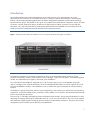
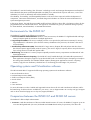
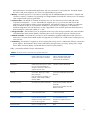
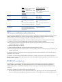
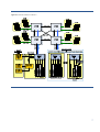
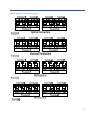
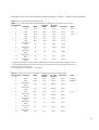
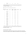
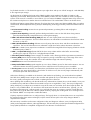
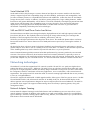
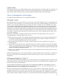
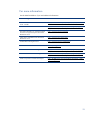
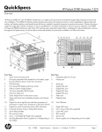
HP ProLiant DL580 G7server technology Technology brief Introduction......................................................................................................................................... 2 Environments for the DL580 G7............................................................................................................. 3 Operating systems and Virtualization software ........................................................................................ 3 Comparison between the DL580 G7 and DL580 G5 servers .................................................................... 3 HP servers and balanced architecture..................................................................................................... 5 DL580 G7 architecture......................................................................................................................... 5 Hemisphere mode ............................................................................................................................ 8 Increasing memory performance ...................................................................................................... 10 Memory RAS ................................................................................................................................. 11 I/O technologies ............................................................................................................................... 15 Smart Array P410i controller ........................................................................................................... 17 Serial Attached SCSI ...................................................................................................................... 19 SAS and SATA Small Form Factor hard drives ................................................................................... 19 Networking technologies .................................................................................................................... 19 Network Adapter Teaming .............................................................................................................. 19 Jumbo Frames................................................................................................................................ 20 Server management technologies ........................................................................................................ 20 HP Insight Control .......................................................................................................................... 20 HP Integrated Lights-Out 3 (iLO 3) .................................................................................................... 20 HP Power Regulator ........................................................................................................................... 21 HP Dynamic Power Capping............................................................................................................... 21 Conclusion........................................................................................................................................ 22 For more information.......................................................................................................................... 23 Call to action .................................................................................................................................... 24 Introduction The seventh generation HP ProLiant DL580 Server series stands out as a major advancement over earlier generations of four-socket servers. The DL580 G7 (Figure 1) features improved HP architecture, advanced RAS features, enhanced HP Integrated Lights-Out (iLO 3) remote management capabilities, and the latest technologybased hardware options. The DL580 G7 also gives you excellent system performance using Intel® Xeon® E7 series processors, and the 7500 series memory architecture, a large memory footprint, numerous I/O slots and disk subsystems. This paper discusses the key technologies that make the ProLiant DL580 G7 an excellent choice for enterprise customers seeking enhanced performance and investment protection. Figure 1: The design of the HP ProLiant DL580 G7 server incorporates the latest technologies and features. The DL580 G7 benefits from a modular architecture. It offers a front-serviceable component drawer for the processor and memory modules. It also features memory cartridges, several I/O slot options, a standard peripheral module, four redundant power supplies, and robust power distribution. At its initial launch, the DL580 G7 supported up to 1 TB of system memory (64 x 16 GB DIMMs) using eight memory cartridges. Now, after the introduction of the 32 GB DDR3 DIMM module, the system supports up to 2 TB (64 x 32 GB DIMMs) of memory. This enables the server to address the rapid requirements of maximum memory footprint. The DL580 G7 supports dual-socket and four-socket configurations with connectivity to all PCIe slots and peripheral components. It uses all available memory controllers, memory buffers, I/O controllers, and Quick-Path Interconnect® links to connect the four processors. The server has 11 full-height, full-length PCIe slots and flexible sub-IO modules. They position the DL580 G7 to take advantage of emerging technologies with flexible choice of x4, x8, and x16 PCIe Gen 2 slots. Four power supplies and distributed voltage-regulator technology provide robust power-distribution architecture. The power and cooling management system increases power efficiency in the DL580 G7. 2 The DL580 G7 uses HP’s leading “Sea of Sensors” technology to track and manage the temperature and health of both individual subsystems and field-replaceable units (FRU). At a reduced level of power and noise, a set of four redundant (3+1) fans run efficiently and cool the DL580 G7 reliably. The reliability, serviceability, and manageability features in the server have improved with the development of components, interconnect fault tolerance, structured design and validation as well as the renewed ProLiant iLO3 system management processor. In the server chassis, the eight front-serviceable small form factor (SFF) drive bays offer a low-latency solution for hotplug RAID disk drives and solid-state drives. The support for external drives gives you additional storage capacity for direct-attached, network-attached, or SAN-attached solutions. Environments for the DL580 G7 The DL580 G7 is ideal for the following environments: Server Consolidation and Virtualization–Within a virtual environment, the DL580 G7’s high-bandwidth and large memory footprint speed the execution of multiple applications. Large Enterprise Database–The server’s multiple processor cores provide the performance necessary for mining large databases for information. (The closer the memory’s database to the processor, the shorter is the time to access the data.) Virtual Desktop Infrastructure (VDI)–The DL580 G7’s large memory footprint efficiently utilizes VDI thin clients. (Each client requires approximately 4 GB of memory.) The server’s high I/O capacity allows many VDI clients to move a large amount of small data packet traffic. Web Hosting–The DL580 G7’s memory footprint optimally meets the memory requirements and demands of webhosted applications. High Performance Numeric Computing– The DL580 G7 easily handles the high I/O bandwidth requirements of these applications through its support of up to three double-wide x16 General- Purpose Computing on Graphics Processing Units (GPGPUs). The GPGPUs offload repetitive floating-point applications (numeric computing intensive, high precision arithmetic). GPGPUs have a 10x floating point advantage over processors. Operating systems and Virtualization software The HP ProLiant DL580 G7 supports the following operating systems and virtualization software: Microsoft Windows Server Red Hat Enterprise Linux (RHEL) SUSE Linux Enterprise Server (SLES) Oracle Solaris VMware Citrix XenServer For more information on HP's Certified and Supported ProLiant Servers for OS and Virtualization Software and for the latest listing of software drivers available for your server, see our Support Matrix at www.hp.com/go/ossupport and our driver download page at www.hp.com/support/DL580G7. Comparison between the DL580 G7 and DL580 G5 servers The DL580 G7 offers multiple enhancements: Processors—With the introduction of the new Intel® Xeon® Processor E7 series, the DL580 G7 supports up to 40 cores and 80 hyperthreads (10 cores/20 threads and 30MB shared cache per processor). This allows for 3 better performance of multithreaded applications and more resources for virtual machines. The Intel® Xeon® Processor 7500 series support up to 8 cores (16 hyperthreads) per processor. Memory—With the support for a new Memory Cartridge and 32 GB DDR3 DIMM, the DL580 G7 supports 2TB of memory capacity. In addition, by supporting low-voltage DIMMs, the DL580 G7 reduces power consumption when compared with previous generations. Expansion Slots—The DL580 G7 features PCI Express Gen 2.0. This achieves twice the bandwidth when compared to PCI-Express 1.1 in G5. The DL580 G7 supports up to (11) I/O slots with dual IOH. It also supports up to three 300 W Graphic Cards and GPGPUs. The DL580 G7 features a modular I/O subsystem (base I/O feature set plus an I/O expansion module) for more choices in configuration. The DL580 G7 standard configuration is five PCI-Express I/O slots. Upgrade the server with the optional 6-slot PCI-Express or PCI-X modules for a maximum number of 11 slots. Storage Controller—The DL580 G7 has an integrated Smart Array P410i storage controller and comes standard with Flash-Backed Write Cache (FBWC), eliminating the worries of losing data with loss of battery power. Network Controller—The DL580 G7 provides two more embedded 1-gigabyte (GbE) Ethernet NIC ports for a total of four. An optional NC524SFP module will upgrade two of the ports to 10 GbE without requiring the use of an I/O slot. Redundancy—The DL580 G7 supports up to four hot-plug fans and up to four 1200W 94% efficient, common-slot power supplies. The DL580 G7 offers memory redundancy through memory mirroring, sparing, ECC, Single Device Data Correction (SDDC), and Double Device Data Correction (DDDC). Table 1 presents the DL580 G7major enhancements. Table 1. DL580 G5 and G7 components have significant differences. Component Chipset DL 580 G7 Intel® 7500 Chip set with highspeed interconnects at 6.4GT/s DL 580 G5 Industry Standard Intel® 7300 Chip set with four high-speed interconnects at 1066 MT/s Processors Intel® Xeon® processor E7 series; Up (10 cores/20 threads per CPU); the Intel Xeon 7500 series, supports up to 8 cores Intel Xeon 7300, 7400 series Memory 64 Sockets, DDR3 up to 1066 MT/s 2TB max. New (E7) Memory Cartridge, LV DIMMs ; Intel® 7500 Scalable Memory Buffer 32 Sockets, DDR2 667 MT/s 256 GB max. Storage Controller HP Smart Array P410i Controller HP Smart Array P400i/256 MB Controller HP Smart Array P400i/512 MB BBWC Controller Internal Drive Support 8 SFF SAS/SATA/SSD 16 SFF SAS/SATA NC375i Quad Port GbE Multifunction NIC; optional Dual Port 10 GB E upgrade Two embedded NC373i Multifunction Gigabit Network Adapters Up to 11 FL/FH I/O slots Base Network Controller Expansion Slots 4 Base : 2 PCI-E 2.0 x16, 3 PCI-E 2.0 x8 Optional Mezzanines Option 1: 2 PCI-E 2.0 x16, 4 PCIE 2.0 x8 Option 2: 1 PCI-E 2.0 x16, 2 PCIE 2.0 x8, 1 PCI-E 2.0 x4, 2 PCI-X 4 PCI-E 1.1 x8, 4 PCI-E 1.1 x4 Optional Mezzanines 3 PCI-X 100MHz 3 PCI-E 1.1 x8 Up to 11 slots supported; slots 911 low profile** USB Ports Front: USB (2) Rear: USB (2) Internal: USB (1)/ SD slot (1) Front: USB (2) Rear: USB (2) Internal: USB (1) Redundancy Fan: Hot-Plug, N+1 redundant fans Power: Up to (4) x 1200W 94% efficient, common slot; optional Fans: (6) Hot-Plug redundant fans Power: (2) or four depending on the model Management ProLiant Onboard Administrator featuring the HP Integrated LightsOut 3 (iLO 3) Integrated Lights Out 2 HP servers and balanced architecture HP servers achieve a balanced architecture through superior engineering of fundamental elements. These elements include mechanical infrastructure, power, cooling, processor, and memory as well as I/O devices, storage, boot, networking, and interconnecting components. A balanced architecture involves: Compute capability based on processor core count, cache size per processor, and processor socket count Low-latency processor-to-memory bandwidth, commensurate with this compute capability Memory footprint that maximizes bandwidth and capacity with power-efficiency and performance without compromising quality or reliability Application-appropriate I/O devices Closely-coupled and balanced processor-to-memory and processor-to-I/O ratios Mechanical design that ensures optimum levels of cooling, stability, and serviceability through space-efficient and modular partitioning By designing a balanced architecture, HP ensures that all subsystems perform effectively under a broad range of applications and workloads. For example, a virtual machine (VM) benefits from memory, coupled to the processor responsible for that VM. In addition, a server needs to have appropriate levels of I/O bandwidth and CPU capabilities to ensure that every VM has the resources it needs. DL580 G7 architecture The DL580 G7 is a powerful, 4U enterprise server incorporating technologies that extends the capabilities of industry-standard x86 computing. This high-performance server can run both 32-bit and 64-bit applications simultaneously. There is no performance penalty when the server uses an operating system that supports 64-bit extensions. The server’s architecture includes the following essential features: The new Intel Xeon Processor E7 series allows the DL580 G7 to support up to 40 cores and 80 hyperthreads (10 cores/20 threads and 30MB shared cache per processor. This design allows for improved performance of 5 multithreaded applications and provides more resources for virtual machines. The Xeon 7500 series processor supports up to eight cores (16 hyperthreads) per processor. The Intel 7500 chipset Up to 2.0TB (32 GB DDR3 DIMMs) with a new (E7) Memory Cartridge Five PCIe 2.0 slots are standard, with the choice of adding one of two optional Mezzanine modules. One option provides PCI-X slots; the other option provides additional PCIe slots. NC375i Quad Port GbE Multifunction NIC; optional Dual Port 10 GbE upgrade HP Integrated Lights-Out 3 management (iLO 3) The DL580 G7 uses the next generation Intel Xeon Processor E7 and 7500 series processor. Its architecture departs radically from Intel processors based on front-side bus architecture. The front-side bus uses an embedded memory controller to produce a common share point for memory access to all processors. The next-generation Xeon processors use NUMA (Non-Uniform Memory Access) architecture that incorporates QuickPath Interconnect (QPI) links for point-to-point connectivity between the server’s four processors, providing dedicated, local memory for each processor. This new architecture includes a memory buffer for each scalable memory interfaces (SMI) in its memory subsystem, allowing for enhanced memory expansion. As a result, the DL580 G7 server offers over twelve times the memory bandwidth of the previous-generation Intel Xeon 7400 platforms and eight times the memory footprint (2TB with 64 x 32 GB DDR3 DIMMs). The combination of enhanced processor cores, more cores, more memory controllers, higher-speed memory and I’O interconnect, higher memory footprint produce dramatic level of performance, posting the highest-ever jump from a previous generation processor. The DL580 G7’s new architecture adds new reliability, availability and serviceability (RAS) features traditionally found in the Intel Itanium processor family. An example is the architecture for HP Memory Quarantine. Intel’s Machine Check Recovery (MCA Recovery) is the basis of HP Memory Quarantine. Intel’s processor advantages include: Built on Intel's 45nm (7500 series) and 32nm (E7 series) High-K Metal Gate technology process Up to 10 and 8 cores per processor Up to 40 threads per processor with Intel Hyper-Threading Technology QuickPath architecture with four high-bandwidth links Up to 30MB of shared cache per processor Integrated memory controllers Intel Turbo Boost Technology Intel scalable memory buffer (SMB) and scalable memory interconnects (SMI) Up to 6.4 the memory bandwidth of previous generation Advanced RAS capabilities 2.3 billion transistors 6 Figure 2. HP ProLiant DL580 G7 architecture 7 Memory Subsystem Architecture The HP ProLiant DL580 G7 provides a 2TB memory footprint and supports up to 64 DDR3 RDIMMs. Each of the server’s four processors receives 16 RDIMM sockets in two easily serviceable memory cartridges. The DL580 G7 supports 2, 4, 8, 16, and 32GB RDIMMs. The server incorporates four processors. Each processor contains two memory controllers as shown above in Figure 2. Each memory controller has two Scalable Memory Interface (SMI) links operating in lockstep. Each SMI link connects to a scalable memory buffer (SMB). The SMB converts SMI to DDR3 and expands memory capacity of the system. Each SMB supports two DDR3 channels, and each DDR3 channel can support up to two DIMMs for eight DIMMs per memory cartridge, 16 DIMMs per processor, and 64 DIMMs per system. The new Intel Xeon Processor E7 and 7500 series memory architecture take advantage of multiple stages of memory interleaving to reduce the perceived latency and increase throughput. The scalable memory buffer (SMB) prevents the varying number of installed DIMMs (or their electrical loads) from affecting the processor’s memory speed. The DL580 G7 runs all DIMMs at the highest possible speed that a given processor supports. The DDR3 memory speed is a function of the QPI bus speed supported by the processor. For example, processors with a QPI speed of 6.4 GT/s run memory at 1066 MT/s. Processors with a QPI speed of 5.6 GT/s run memory at 978 MT/s, and processors with a QPI speed of 4.8 GT/s run memory at 800 MT/s. Hemisphere mode The memory architecture for the Intel Xeon Processor E7 utilizing the 7500 Series chipset design includes a highperformance interleaving technology called Hemisphere mode (see Figure 3.) It combines the tracking resources of both memory controllers within each processor to speed the movement of data along a cache-line by a process called pipelining. To utilize Hemisphere mode, the system processors must have identical DIMM populations behind both of their memory controllers. To enable each processor to enter the Hemisphere mode, you must install and populate both DIMM memory cartridges with identical memory capacities based on the DIMM installation guidelines. Hemisphere mode produces the best overall performance for many applications. You can disable Hemisphere mode if it produces lower performance for a particular application (for example, an RBSU option). You can obtain better performance when populating all cartridges with either four or eight dual- or quad-rank DIMMs. (The server does not support memory mirroring when it enables Hemisphere mode.) Figure 3 below shows six examples of Hemisphere vs. Non-Hemisphere populations. 8 Figure 3: Hemisphere vs. Non-Hemisphere populations 9 The above Non-Hemisphere Example 5 and Example 6 illustrate: Each memory controller must have a memory cartridge DIMM configurations of each memory cartridge connected to controller 1 and 2 of a processor must be identical. Note that “Example 4” is a Hemisphere configuration. The two cartridges connected to each processor share identical configurations, but Cartridge 1 and Cartridge 2 are not identical to Cartridge 3 and Cartridge 4. Increasing memory performance For improved performance, successive cache lines interleave between the DIMMs and the lockstep SMI channels of the processor’s two memory controllers. This alternate-layer arrangement of cache lines boosts performance by allowing adjacent cache lines to reside on different memory controllers, different SMIs, different DIMMs, and DIMM ranks. SMI channel DIMMs are evenly populated. If a given SMI channel pair has more DIMMs than other channels, the extra memory will not receive the benefit of the interleaving mechanism. Achieving optimum performance The DL580 G7 supports 64 DIMMs slots across four multi-core processors. While there are multiple DIMM population configurations that may support the desired total memory size, you can only achieve optimal performance when populating DIMMs that can take advantage of the Intel Xeon Processor E7 and 7500 series architecture. The Hemisphere Population Diagram (Figure 3) displays how to achieve the best performance for a given memory and processor configuration. Follow these rules: Use both memory controllers inside the processor and populate two memory cartridges for each installed processor. This is the top contributor to memory bandwidth performance. 10 Populate each DDR3 channel in each memory cartridge. To achieve this, the minimum DIMM count per cartridge is four DIMMs installed in DIMM pair locations A and B. This is the second largest contributor to performance. Use dual-rank DIMMs for significantly better performance than that of single-rank DIMMs. Quad-rank DIMMs provide a greater performance boost. The number of ranks per DIMMs is the third largest contributor to performance. Use all installed processors in Hemisphere mode for the best performance. Installation of four or eight DIMMs per cartridge optimizes Hemisphere mode. You achieve maximum throughput when you populate each memory cartridge with eight quad-rank DIMMs. Memory RAS Advanced ECC (Error Checking and Correcting) is the default memory RAS option for the DL580 G7. ECC gives you the greatest memory capacity for a given DIMM size. To enhance availability, the server supports the following Advanced Memory Protection (AMP) modes: Online Sparing provides protection against persistent DRAM failure. Rank sparing is more efficient than DIMMsparing because it sets aside only a portion of a DIMM for memory protection. Mirrored Memory provides optimum protection against failed DIMMs. If one DIMM in a processor’s memory cartridge experiences an uncorrectable error, the DIMM in the processor’s mirrored cartridge can provide the correct data. Double-Device Data Correction (DDDC) provides the capability to withstand failures in two x4 DRAM devices. DDDC can fix both single-and double-DRAM device memory errors. Advanced ECC memory Advanced ECC memory is the default memory mode for the DL580 G7. It supports up to 2TB of active memory, utilizing 32GB DIMMs. Advanced ECC memory can correct single-bit memory errors and multi-bit memory errors on a single x8 or two adjacent x4 DRAM devices. The DL580 G7 provides notification when correctable errors exceed a predefined threshold. When Advanced ECC detects uncorrectable errors, the server notifies the user and shuts down the operating system. Double Devide Data Correction The DL580 G7 offers DDDC with the Intel Xeon Processor E7 series. DDDC produces significantly less system downtime over SDDC. It can tolerate soft and hard errors encountered in up to two x4 DRAM devices within any DIMM pair. Tolerating memory faults greatly extends system up-time. Using two DIMMs in a pair group, 16 check bits are available to the error correcting algorithm to protect 128 data bits (16 bytes) of data. By reserving one x4 DRAM device in each rank as a spare, the DDDC algorithm assures data availability after hard failures occur within any two x4 DRAM devices. The DDDC algorithm protects against double-device failure of x4 DIMMs. DDDC is disabled if the memory configuration includes a mix of x4 and x8 DIMMs. This scenario will engage SDDC (single-device data correct). Enabling Memory Mirroring will disable DDDC. In DDDC mode, DL580 G7 provides the full memory bandwidth and capacity that is available in the system. There is no capacity or bandwidth overhead associated with enabling DDDC. Online spare memory—rank sparing Online spare memory, or rank-sparing, protects against persistent DRAM failure. Online spare memory monitors DIMMs for excessively frequent correctable errors. It copies the content of an unhealthy rank to an available spare rank in advance of multi-bit or persistent single-bit failures. Rank-sparing is more efficient than DIMM-sparing because only a portion of a DIMM is set aside for memory protection. 11 When the system enables online sparing, the first ranked DIMM pair of 1A/8A are set aside as the sparing ranks, reducing available memory. If a DIMM rank on either of the SMI buses exceeds its correctable ECC threshold, the contents of the failing DIMM ranks go to the spare DIMM ranks. Once the copy is complete, all memory accesses to the previous failing DIMM ranks go to the spare DIMM ranks. During normal operation, there is no performance penalty for rank-sparing. Upon detection of a frequent error, the performance impact occurs only during the time it takes to copy the data from the failing rank to the spare rank. Lockstep memory mode As Figure 4 below and Table 1 below both illustrate, each memory controller has two scalable memory interfaces (SMI). Each SMI connects to one scalable memory buffer (SMB) and couples with two DDR3 buses. Each DDR3 bus runs in lockstep with its DIMM pair of the other SMB. Running DIMM pairs in lockstep provides for wider error detection and correction coverage. Through lockstep operation, the memory subsystem of the DL580 G7 server can tolerate a x4 or a x8 DRAM device failure. Lockstep memory mode uses two SMI links to produce a higher level of fault tolerance than the normal 64+8 bit ECC. In lockstep mode, two channels operate as a single channel to form 16 redundant bits for each 128 data bits. Each write and read operation moves a 144 data word. A 64-byte cache line splits across 2 DDR3 buses with a burst length of 4. The split lines provide 2x 8-bit error detection and 8-bit error correction for a single x4 or x8 DRAM within a DIMM pair. Using DIMM Isolation, the DL580 G7 detects and corrects errors associated with failing DIMMs that have crossed a correctable error threshold. It detects and corrects DIMM errors caused by single x4 or x8 DRAM device failure. The DL580 G7 identifies the individual DIMM associated with correctable errors. It also identifies the DIMM pair associated with a failed DRAM device (detected and corrected) or with non-correctable errors (detected and uncorrected).Mirrored memory Memory Sparing cannot correct errors that evade correction by the ECC or SDDC. By providing added redundancy in the memory subsystem, Memory Mirroring delivers the greatest protection against memory failure beyond ECC, SDDC, and Memory Sparing. In the mirrored mode, each lockstep DIMM pair in a memory controller has a mirrored DIMM pair on the other memory cartridge. After the DL580 G7 detects an uncorrectable memory error from a DIMM pair of a memory cartridge, the server avoids a system crash by reading the mirrored DIMM pairs from the other memory cartridge. In this case, the system management disables the failed DIMM. Later memory reads and writes will occur only on the mirrored DIMM pairs. Note that in Memory Mirroring mode, useable memory capacity is half of the available memory, and the perceived available memory bandwidth is about half of available memory bandwidth. For population guidelines, see the DL 580 G7 User Guide at http://h20000.www2.hp.com/bc/docs/support/SupportManual/c02267159/c02267159.pdf. Figure 4 displays the server’s memory expansion architecture. 12 Figure 4. DL580 G7 memory expansion boards Processor 1 Processor 2 Processor 3 Board 8 Board 7 Board 6 Board 5 DL580 G7 Memory Boards (Front of Chassis) Board 4 DIMM Board 2 Board 3 DIMM Board 1 Processor 4 DDR3 RDIMM DDR3 RDIMM DDR3 RDIMM DDR3 RDIMM Voltage Regulators (VRDs) DDR DDR DDR3 RDIMM DDR3 RDIMM DDR3 RDIMM DDR3 RDIMM PCIe Type Connector 13 In memory expansion architecture, each processor has two embedded memory controllers. Each memory controller controls two high-speed scalable memory interfaces (SMI). Each SMI link expands to two DDR3 buses via a scalable memory buffer (SMB). Each memory controller runs its two SMI links in lockstep. Memory expansion architecture furnishes a level of fault tolerance to sustain the failure of any DRAM device within any pair of lockstep DIMMs. This memory subsystem design supplies enhanced performance in Advanced ECC mode. Additional memory protection comes through online spare, mirrored memory and DDDC modes. The DL580 G7 Advanced ECC supports up to 2TB of active memory utilizing 32 GB DDR3 RDIMMs. The server provides notification if the level of correctable errors exceeds a pre-defined threshold. Standard ECC can only correct single-bit memory errors. Advanced ECC corrects any single-bit and multi-bit memory error associated with a single DRAM device (SDDC). Online spare memory gives additional protection against degrading DIMMs. For example, rank sparing allows the allocation of a rank in a DIMM as the online spare memory for a collection of two DIMMs. If one of the non-spare DIMMs exceeds a threshold for correctable memory errors, the server automatically copies the contents of the degraded memory to the online spare rank. Then the server deactivates the failing memory rank, and automatically switches over to the online spare rank. This reduces the likelihood of uncorrectable memory errors, which could result in server downtime. Online spare memory protection is available without any operating system support. Mirrored memory protects against failed DIMMs. It supports up to 1 TB of active memory and 1 TB of mirrored memory using 32-GB DIMMs. Within each processor, mirroring occurs on the memory controller level. Note that each memory controller supports two SMI links. When two memory controllers mirror each other, DIMM pairs associated with each memory controller maintain a copy of all memory contents. Memory writes go to DIMM pairs of both memory controllers. Memory reads come from only one set of DIMM pairs of the two memory controllers, unless an uncorrectable error occurs. If a memory read on one DIMM pair returns incorrect data due to an uncorrectable memory error, the system automatically retrieves the correct data from the mirrored DIMM pair. Systems do not lose mirroring protection because of transient and soft uncorrectable errors and maintain mirroring protection unless memory in both DIMM pairs fail. 14 I/O technologies The DL580 G7 supports up to eleven I/O full length, full height expansion slots with the available option cards installed. The standard configuration includes five slots, 2 PCIe x8 2.0 and 3 PCIe x4 2.0. Two optional cards are available: Option No. 1, Standard PCIe 1 PCIe 2.0 x4, 1 PCIe 1.0 x4 and 4PCIe 2.0 x8 Option No. 2, Combination PCI—X, PCIe and 300W GPU 2 PCI-X 64 bit, 1PCIe 2.0 X4, 2PCIe 2.0 X16 PCIe 2.0 (Gen 2) is an expansion bus technology that arises from earlier PCI and PCIe technologies. The server uses a serial interface running at 5 Gb/s. A PCIe interface supports one or more lanes, as determined by the PCIe slot. Multiple-lane connections are x4 for a 4-lane link, x8 for an 8-lane link, and x16 for a 16-lane link. Each PCIe 2.0 lane consists of four wires for a differential pair of transmit-and-receive signals. Each runs serially at 5 Gb/s with an 8b10b encoding (10-bit symbols to represent 8 data bits). Each PCIe 2.0 lane has a bandwidth of 512 MB/s in each direction (for a total bandwidth of 1 GB/s per lane). The end ports of PCIe links automatically negotiate the highest bit rate and the highest number of lanes that the slot and the add-in card support. A PCIe expansion card can run correctly in any slot it will fit. With enormous aggregate IO bandwidth, the DL580 G7 supports concurrent operation of all 11 slots. The server offers the support for dual- and triple-slot, high-powered PCIe add-in cards. With unencumbered bandwidth to the host memory, such 200W and 300W add-in boards may perform high-performance computations demanded by vector processors and IO accelerators. 15 Refer above to the Figure 2 block diagram for details and below to Tables 1, 2 and 3 for slot assignments. Table 1. Main I/O Board Standard Expansion Slots NOTE: Up to 11 slots supported; all full-length-full-height. Standard: 2 PCI-E 2.0 x8, 3 PCI-E 2.0 x4. Expansion Slot # Technology Width Connector Width* Bus / Dev Number** Form Factor Notes 1 N/A N/A N/A N/A N/A N/A 2 N/A N/A N/A N/A N/A N/A 3 N/A N/A N/A N/A N/A N/A 4 N/A N/A N/A N/A N/A 5 N/A N/A N/A N/A N/A 6 N/A N/A N/A N/A N/A 7 PCI Express Gen2 x4 x8 0/0A FH/FL 8 PCI Express Gen2 x4 x8 0/09 FH/FL 9 PCI Express Gen2 x8 x16 0/07 FH/FL 10 PCI Express Gen2 x4 x8 0/01 FH/FL 11 PCI Express Gen2 x8 x16 0/05 FH/FL * Default bus assignment. Inserting cards with PCI bridges may alter the actual bus assignment number. ** Slots enumerated differently based on OS. MS OS's enumerate from lowest to highest Device ID by bus (starting with the lowest bus). FL= Full length; FH = Full height; LP = low profile. Table 2. Expansion Slots With I/O Expander (combination PCI-X, PCI-e and 300W GPU Expansion Slot # Technology Width Connector Width* Bus / Dev Number** Form Factor Notes 1 PCI-X 64-bit N/A 82/01 FH/FL 100MHz 2 PCI-X 64-bit N/A 82/02 FH/FL 100MHz 3 PCI Express Gen2 x16 x16 80/07 FH/FL 4 PCI Express Gen2 x4 x8 80/01 FH/FL 5 N/A N/A N/A N/A N/A 6 PCI Express Gen2 x16 x16 80/03 FH/FL 7 PCI Express Gen2 x4 x8 0/0A FH/FL 8 PCI Express Gen2 x4 x8 0/09 FH/FL 9 PCI Express Gen2 x8 x16 0/07 FH/FL 10 PCI Express Gen2 x4 x8 0/01 FH/FL N/A 16 11 PCI Express Gen2 x8 x16 0/05 FH/FL * Default bus assignment. Inserting cards with PCI bridges may alter the actual bus assignment number. ** Slots enumerated differently based on OS. MS OS's enumerate from lowest to highest Device ID by bus (starting with the lowest bus). FL= Full length; FH = Full height; LP = low profile. Table 3. Expansion Slots With I/O Expander (Standard PCI-e Option) Expansion Slot # Technology Width Connector Width* Bus / Dev Number** Form Factor 1 PCI Express Gen1 x4 x8 80/00 FH/FL 2 PCI Express Gen2 x8 x16 80/09 FH/FL 3 PCI Express Gen2 x8 x16 80/07 FH/FL 4 PCI Express Gen2 x4 x8 80/01 FH/FL 5 PCI Express Gen2 x8 x16 80/05 FH/FL 6 PCI Express Gen2 x8 x16 80/03 FH/FL 7 PCI Express Gen2 x4 x8 0/0A FH/FL 8 PCI Express Gen2 x4 x8 0/09 FH/FL 9 PCI Express Gen2 x8 x16 0/07 FH/FL 10 PCI Express Gen2 x4 x8 0/01 FH/FL 11 PCI Express Gen2 x8 x16 0/05 FH/FL Notes * Default bus assignment. Inserting cards with PCI bridges may alter the actual bus assignment number. ** Slots enumerated differently based on OS. MS OS's enumerate from lowest to highest Device ID by bus (starting with the lowest bus). FL= Full length; FH = Full height; LP = low profile. Smart Array P410i controller The HP ProLiant DL580 G7 includes the Smart Array P410i controller. It is the HP PCI Express 2.0 (PCIe) Serial Attached SCSI RAID controller. The controller has eight ports and uses DDR2-800 memory. It is ideal for RAID 0/1, 1+0, and 5+0. You can upgrade it with the 512 MB BBWC module and Smart Array Advanced through the license 17 key for RAID 6 and 6 +0. The SA-P410i supports up to eight drives and up to 4.8 TB of storage (8 x 600 GB HDD). It also supports tape storage. On the SA-P410i, a flash-backed write cache (FBWC) module comes standard with either 512 MB or1 GB, depending on the model. Battery-backed write cache (BBWC) modules are also available on factory-configured systems. In the event of a controller or server failure, you can remove the BBWC equipped Smart Array cache from the SA-P410i and place it on another SA-P410i controller board. The cached data will move to the disk drives. The following features support failure detection. They keep the server running and data available while you replace a failed drive: HP developed Monitoring Analysis and Reporting Technology to detect possible disk failure before it occurs. Drive Parameter Tracking monitors drives operational parameters, predicting failure and notifying the administrator. Dynamic Sector Repairing continually performs background surface scans on the disk drives during inactive periods and automatically remaps bad sectors, ensuring data integrity. RAID 6 with Advanced Data Guarding (ADG) allocates two sets of parity data across drives and allows simultaneous write operations. This level of fault tolerance can withstand two simultaneous drive failures without downtime or data loss. RAID 5 (Distributed Data Guarding) allocates one set of parity data across drives and allows simultaneous write operations. This level of fault tolerance can withstand a single drive failure without downtime or data loss. RAID 5+0 is a RAID 0 array striped across elements. It combines the straight block-level striping of RAID 0 with the distributed parity of RAID 5. RAID 1, 1+0 (Drive Mirroring) allocates half of the drive array to data and the other half to mirrored data, providing two copies of every file. It is a high-performance RAID. Smart Array Cache Tracking monitors integrity of controller cache, allowing pre-failure preventative maintenance. Recovery ROM protects from firmware image corruption by storing a redundant copy of the image. If the active image becomes corrupt, the controller will use the redundant image and continue operating. DRAM ECC detects and corrects data bit errors. Battery-Backed Write Cache upgrade supplies up to two days of battery power for data cache retention. You can extend the retention time during system power down when the server's auxiliary power is available. On-Line spares minimize downtime, reconstruct data, and facilitate a quick recovery from drive failure. You can install up to two spare drives before a drive failure. If a failure occurs, the recovery begins automatically with an On-Line Spare and data reconstructs. Online Drive Flashing is available on the SA-P410. With Online Drive Flashing, you can download an updated hard disk drive (HDD) firmware image to the controller and update all of your SAS HDDs the next time you reboot the server, greatly reducing the time involved in updating disk drive firmware. Mirror Splitting and recombining with the HP Smart Array Advanced Pack (SAAP) let you divide a RAID 1 array into two RAID 0 arrays and later combine the two RAID 0 arrays into a single RAID 1 array. The Array Configuration Utility (ACU) lets you combine any two RAID 0 arrays of the same size and select which drive keeps the data. This feature is only available offline. You must boot to the Smart Start CD and run ACU from there. Typically, you use this feature when testing out a software patch. You could split the mirror as a means to save the current data and then perform any type of destructive software update necessary, keeping the resulting data set or reverting back to the old data. BBWC is not required to enable this feature. Capacity expansion adds drives to a configured array. The logical drives (or volumes) that exist in an array before the expansion takes place remain unchanged, only the amount of free space in the array changes. BBWC is required for this feature. All Smart Array controllers use the same configuration utility and diagnostic software, Array Configuration Utility (ACU), and management software, HP Insight Manager. The SA-P410 also provides Option ROM Configuration for Arrays (ORCA) that allows a simplified configuration tool at the time of controller boot. 18 Serial Attached SCSI Serial Attached SCSI (SAS) leverages a common electrical and physical connection interface with Serial ATA (SATA). It supports logical SCSI compatibility along with SCSI reliability, performance and manageability. SAS provides investment protection in compatible SCSI software and middleware. It offers the choice of direct-attach storage devices (SAS or SATA). In addition, SAS allows greater performance, longer cabling distances, smaller form factors and greater addressability. All will lead to a new level of flexibility when deploying mainstream data center servers and subsystems. This compatibility gives you many choices for server and storage subsystem deployment, by leveraging the SATA development effort on smaller cable connectors. It gives customers a downstream compatibility with desktop-class ATA technologies. SAS and SATA Small Form Factor hard drives The SAS architecture enables system designs that deploy high-performance SAS and high-capacity SATA Small Form Factor (SFF) drives. This capability offers a broad range of storage solutions that give IT managers the flexibility to choose storage devices based on reliability, performance, and cost. SFF drives provide higher performance than large form factor drives. The smaller SFF platters reduce seek times because the heads have a shorter distance to travel. RAID performance improves by increasing the numbers of spindles. HP ships SATA drives with Drive Write Cache (DWC) disabled. We selected the preset configuration to provide greater safety for drive data in case of a sudden power loss when there is no battery on the controller to protect the cache. Enabling DWC may result in data loss if power fails and there is no power protection. Native Command Queuing (NCQ) increases SATA HDD performance by prioritizing read and write command execution. This reduces unnecessary drive head movement and increases performance, especially in server or storage-type applications with outstanding multiple simultaneous read/write requests. Without NCQ, the drive can process and complete only one command at a time. You must activate NCQ in both the controller and the drive. Networking technologies The DL580 G7 includes the integrated NC375i network controller. The NC375i is a quad port Gigabit Server Adapter that allows access to four 1 GbE ports. The NC375i has an eight lane (x8) PCI Express data path. With four ports on a single integrated controller, this density design contributes to saving server I/O slots. It also makes the configuration ideal for virtualization and security applications, server consolidation, and increased network segmentation. The quad port NC375i meets the needs of customers wanting high bandwidth but are not yet ready to move to 10 Gigabit Ethernet. The NC375i supports the NC524SFP 10 GbE upgrade module, allowing two of the four ports to move to 10 GbE. The NC524SFP module—with its theoretical maximum of 40 Gbps, dual port, bi-directional full duplex mode— delivers optimum network performance designed to improve response time and remove bottlenecks. The NC375i provides full driver support. The support includes teaming drivers for all major operating systems, along with management utilities. Network Adapter Teaming ProLiant Network Adapter Teaming provides fault tolerance and load balancing across a team of two or more network adapters. The team of adapters works together as a single virtual adapter. Support for several different types of teaming is included. Teaming options offers an easy, efficient, and cost-effective way to provide network fault tolerance and increased network bandwidth. 19 Jumbo Frames Jumbo frames (also known as extended frames) permit a 9K byte transmission unit (MTU), which is six times the size of a standard 1500-byte Ethernet frame. The NC375i supports jumbo frames to achieve higher throughput and better CPU utilization. Jumbo frames are particularly useful for database transfers and tape backups. Server management technologies The DL580 G7ships standard with sever management capabilities. HP Insight Control HP Insight Control gives you more control over your ProLiant servers. With Insight Control, you can deploy ProLiant servers quickly. You can catalog your environment accurately, and monitor its health reliably to pinpoint failures. In addition, you can manage systems remotely away from your office, and optimize power confidently. As a result, you can reduce unplanned downtime and deliver stable IT services to your business users. You can also respond to pressing business needs faster by facilitating the rapid rollout of new IT services and optimizing the utilization of compute resources and data center facilities. HP Insight Control for Microsoft System Center and HP Insight Control for VMware vCenter deliver hardware management expertise into Microsoft System Center and VMware vCenter environments. Customers need only purchase one Insight Control license to take advantage of both System Center and vCenter integrations HP Insight Control helps you unlock the potential of your infrastructure with deep insight, precise control, and ongoing optimization. With HP Insight Control, you can: Deploy ProLiant servers quickly with a reliable drag-and-drop tool that can turn a manual server deployment into an unattended, repeatable, and automated deployment. Insight Control includes a complete set of wizarddriven server migration capabilities (P2P, P2V, V2P, and V2V). Monitor ProLiant server health with one simple, integrated interface and receive notification of any actual or impending failure Control ProLiant servers from anywhere, regardless of location, and improve system recovery times. With Insight Control, you can eliminate the cost of visiting servers anywhere in the world at anytime. HP Insight Control taps into and unleashes the HP iLO Advanced technology, a set of licensed embedded management capabilities that enhances the remote management experience Measure power consumption, reduce power usage, and reclaim trapped power and cooling capacity to extend the life of data centers Support all leading hypervisors, such as Microsoft Hyper-V, VMware vSphere, and Citrix XenServer. You also have the option of Linux-based Central Management Console -Insight Control for Linux for IT shops requiring full-Linux management. HP Integrated Lights-Out 3 (iLO 3) As previously noted, the HP ProLiant DL580 G7 server ships with the iLO 3 management processor onboard. An HP Advanced license either included with the HP Insight Control software or purchased stand-alone, upgrades the iLO firmware, enhancing remote management. The iLO 3 hardware and firmware provide remote server management capabilities over the Ethernet. The iLO 3 management processor remains available whenever power flows to the server―even if the operating system is in shutdown. This feature lets you troubleshoot from a remote location. HP iLO 3 connects through a dedicated Ethernet port. The port can connect to a highly secured, dedicated management network that is out of the server’s data path. Alternately, iLO 3 provides a Shared Network Port (SNP) that allows network access to both iLO and the host server using a single network port. SNP allows routing of iLO network traffic through a sideband connection on one of the server NIC interfaces. Although the iLO traffic shares a 20 port with the server OS traffic, both the iLO processor and the server NIC have their own Media Access Control (MAC) address, which gives iLO and the server separate Internet Protocol (IP) addresses. The SNP simplifies hardware installation and reduces hardware costs because corporate and iLO network traffic comes through the system NIC. Advantages of iLO 3 With HP iLO3, you can: Reduce expense and travel costs by accessing a secure Remote Console to the server from anywhere. Use the shared iLO 3 Remote Console to collaborate with up to six server administrators Remotely mount high-performance Virtual Media devices to the server from anywhere on the network Securely and remotely control the power state of the server Send alerts from iLO 3 regardless of the state of the host server Access advanced troubleshooting features through the iLO 3 interface Experience a fast Remote Console incorporating the newest technologies like Simple Network Time Protocol (SNTP) and IPMI over LAN (Intelligent Platform Management Interface) DCMI (Data Center Manageability Interface) Launch URL or scriptable Virtual Media from Remote Console Experience a streamlined user interface using Web 2.0 technologies Experience AES (in addition to RC4) encryption in the hardware for improved performance HP Power Regulator The DL580 G7 includes HP Power Regulator, an innovative OS-independent power management tool. HP Power Regulator is a ROM-based utility used to set the server to power modes: Static high power—Server runs continuously in the highest performance state Static low power—Server runs continuously in the lowest power state Dynamic power savings—Server processor-power adjusts according to application activity HP Power Regulator improves the energy efficiency of the DL580 G7. Intel processors run at full power when they need to, but with reduced application activity, they run in a power savings mode without performance degradation. RBSU during POST or the iLO 3 remote management console allows selection of the HP Power Regulator modes. HP Dynamic Power Capping Server performance per watt continues to increase steadily. However, the number of watts per server also continues to climb. These increases, combined with the growing number of servers and density in modern data centers, make planning and managing facility power and cooling resources critically important. HP Dynamic Power Capping is a ProLiant power management tool unique to HP and assists the data center administrator with managing these critical tasks. Because it is hardware based, Dynamic Power Capping can control server power consumption quickly. Dynamic Power Capping ensures sudden surges in server power demand do not allow the HP Power Distribution Unit circuit breakers to trip. Administrators can use power consumption information gathered with Insight Control power management software to set appropriate power caps to individual servers. Setting power caps to the peak observed power consumption makes it possible to free up additional power. Power is then available for additional servers. 21 For more information on the topic of HP Power Capping see: http://h20000.www2.hp.com/bc/docs/support/SupportManual/c01549455/c01549455.pdf Conclusion The HP ProLiant DL580 G7 is a 4U rack-optimized, four-processor server. We engineer it for large data center deployments requiring enterprise-class performance, uptime, scalability, and remote management capabilities. The DL580 G7 offers customers running both 32- and 64-bit applications with increased performance and memory bandwidth. This platform’s balance of new system architecture, extensive memory capacity, and I/O throughput provides the high performance needed for large-scale enterprise applications. 22 For more information See the URLs listed below if you need additional information. Type of information Source HP ProLiant DL580 G7 Server series―Models http://h10010.www1.hp.com/wwpc/us/en/sm/WF25a/15 351-15351-3328412-241644-3328422-4142916.html HP ProLiant DL 580 G7 Server User Guide http://h20000.www2.hp.com/bc/docs/support/SupportMa nual/c02267159/c02267159.pdf Up-to-date information on operating systems and versions supported by the HP ProLiant DL580 G7 server http://www.hp.com/go/supportos Latest drivers available for the HP ProLiant DL580 G7 server http://www.hp.com/support/files Details about HP Insight Control http://www.hp.com/go/insightcontrol Information about iLO 3 www.hp.com/go/iLO Information about SAS technology http://h20000.www2.hp.com/bc/docs/support/SupportMa nual/c01613420/c01613420.pdf Details about Serial ATA technology http://h20000.www2.hp.com/bc/docs/support/SupportMa nual/c00301688/c00301688.pdf Smart Array P410i controller QuickSpecs http://h18000.www1.hp.com/products/quickspecs/13201_ div/13201_div.html 23 Call to action Send comments about this paper to [email protected] Follow us on Twitter: http://twitter.com/ISSGeekatHP © Copyright 2011 Hewlett-Packard Development Company, L.P. The information contained herein is subject to change without notice. The only warranties for HP products and services are set forth in the express warranty statements accompanying such products and services. Nothing herein should be construed as constituting an additional warranty. HP shall not be liable for technical or editorial errors or omissions contained herein. Intel, Intel Celeron, Itanium, Intel Itanium, Pentium, and Intel Xeon are trademarks of Intel Corporation in the United States and other countries. TC1006475, June 2011