1
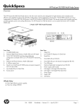
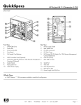
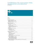
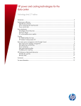
HP ProLiant Intel-based 100-series G6 servers Technology brief, 4th edition Abstract.............................................................................................................................................. 3 Introduction......................................................................................................................................... 3 HP servers and balanced architecture .................................................................................................... 3 Intel Xeon 5500 Series processor technology .......................................................................................... 4 Multi-level caches ............................................................................................................................. 4 Integrated memory controller ............................................................................................................. 5 QuickPath Interconnect controller ....................................................................................................... 5 Hyper Threading.............................................................................................................................. 6 Turbo Boost technology..................................................................................................................... 6 Intel Xeon 5600 Series processor technology .......................................................................................... 6 Advanced Encryption Standard New Instructions ................................................................................. 7 Intel Xeon 3400 Series processor technology .......................................................................................... 7 Memory technologies ........................................................................................................................... 9 DDR3 ............................................................................................................................................. 9 I/O technologies ............................................................................................................................... 12 PCI Express technology................................................................................................................... 13 HP Smart Array and SAS/SATA technology ...................................................................................... 13 Power and thermal technologies .......................................................................................................... 17 Efficient power delivery................................................................................................................... 17 Improved thermal sensors and fan control ......................................................................................... 18 Phase shedding ............................................................................................................................. 18 Managing processor technologies.................................................................................................... 19 Managing memory technologies ...................................................................................................... 19 Managing I/O technologies............................................................................................................ 20 Power Efficiency Mode ................................................................................................................... 20 Power Performance Benchmarks .......................................................................................................... 20 Server management and deployment ................................................................................................... 20 Systems management and monitoring............................................................................................... 21 Remote management and control ..................................................................................................... 21 IPMI 2.0 and DCMI 1.0.................................................................................................................. 24 Server deployment ......................................................................................................................... 24 Security ............................................................................................................................................ 25 OS support ....................................................................................................................................... 25 DL1000 Multi Node server design for scale out computing ..................................................................... 26 Chassis design............................................................................................................................... 26 Fans and fan control....................................................................................................................... 28 Power supply support ..................................................................................................................... 28 Advanced Power Management........................................................................................................ 28 Summary .......................................................................................................................................... 29 For more information.......................................................................................................................... 30 Call to action .................................................................................................................................... 31 Abstract This technology brief describes the key technologies implemented in Intel-based HP ProLiant 100-series G6 servers. The 100-series family includes the ProLiant DL100-series, the ML100-series, and the DL1000 Multi Node architecture. As of this writing, the Intel-based 100-series G6 servers include the ProLiant DL120, DL160, DL180, ML110, ML150, DL170h, DL2x170h, and DL4x170h. For detailed information about these servers, refer to the QuickSpec links listed at the end of this technology brief. Introduction HP ProLiant G6 servers have been the focus of extensive engineering and development. These Intelbased G6 servers are characterized by increased performance, better power efficiency, and more powerful management tools. Several key technologies are included: The Intel® Xeon® Processor 5500 Series The Intel Xeon Processor 5600 Series The Intel Xeon Processor 3400 Series Double Data Rate-3 (DDR3) memory DIMMs Thermal sensors incorporated throughout the ProLiant100-series G6 servers Lights-Out 100i (LO 100i) I/O technologies such as PCIe generation 2 (PCIe 2.0) and faster Smart Array controllers that incorporate common form factor components B110i software RAID with SATA Hot Plug technology Flash-backed write cache for Smart Array controllers Common Slot power supplies to provide the required amount of power and improve power efficiency Management options accessed from the BIOS setup utility that can reduce power and thermal use by power supplies, I/O, processors, and memory The technologies discussed in this paper are implemented in all Intel-based ProLiant 100-series G6 servers. Exceptions are noted where different levels of technology implementation or service exist among individual ProLiant 100-series G6 platforms. For complete specifications of all ProLiant 100-series servers, see the HP website: www.hp.com/products/servers/platforms. HP servers and balanced architecture HP designs cost-competitive, power-efficient servers that use a balanced architecture to address performance requirements and provide value. HP servers achieve a balanced architecture through superior engineering of fundamental elements such as mechanical infrastructure, power, cooling, processor, memory, IO devices, storage, boot, networking, and interconnecting components. A balanced architecture includes the following: Compute capability, processor core count, cache size per processor, and processor socket count Low-latency processor-to-memory bandwidth commensurate with core count Memory footprint and capacity that maximizes bandwidth and capacity with power efficiency and performance without compromising quality or reliability Application-appropriate IO devices 3 Closely-coupled and balanced processor-to-memory and processor-to-I/O ratios Mechanical design that ensures optimum levels of cooling, stability, and serviceability through space-efficient, modular partitioning across the server By designing a balanced architecture, HP ensures that all subsystems can be used effectively under a broad range of applications and workloads. For example, increasing memory capacity asymmetrically will not increase performance as effectively as distributing the same amount of memory across processors and IO devices. Inefficient memory distribution yields diminishing returns on power consumption and cost. A virtual machine (VM), for example, benefits from memory closely coupled to the processor responsible for that VM. Furthermore, a server needs to have appropriate levels of I/O bandwidth and CPU capabilities to ensure that memory can be used effectively by every VM. Intel Xeon 5500 Series processor technology Some ProLiant Intel-based 100-series G6 servers contain the Xeon 5500 Series processors. The processors include four cores, an integrated memory controller, and Intel QuickPath technology to boost bandwidth between processors, memory, and I/O subsystems. Three memory channels from each integrated memory controller to its dedicated memory provide a total bandwidth of 32 GB/s. The Xeon 5500 Series Nehalem microarchitecture is built on hafnium-based, 45 nanometer high-k metal gate silicon technology to reduce electrical leakage. The processors support distributed shared memory, Intel Hyper-Threading technology, and Intel Turbo Boost Technology with Intelligent Power Technology. 1 Multi-level caches Xeon 5500 Series processors have a three-level cache hierarchy (Figure 1): An on-core, 64 kB, Level 1 cache, split into two 32 kB caches: one for data and one for instructions 256-kB, Level 2 cache for each core to reduce latency A Level 3 cache of up to 8 MB shared by all cores 1 For additional information about Intel processors, see the HP technology brief titled AMD Opteron™ and Intel® Xeon® x86 processors in industry-standard servers”: http://h20000.www2.hp.com/bc/docs/support/SupportManual/C02731435/C02731435.pdf. 4 Figure 1. Block diagram of three-level cache hierarchy for Intel Xeon 5500 Series processors The Level 3 cache is shared and inclusive, which means that it duplicates the data stored in the Level 1 and Level 2 caches of each core. This guarantees that data is stored outside the cores and minimizes latency by eliminating unnecessary core snoops to the Level 1 and Level 2 caches. Flags in the Level 3 cache track which core’s cache supplied the original data. Therefore, if one core modifies another core’s data in Level 3 cache, the Level 1 and Level 2 caches are updated as well. This eliminates excessive inter-core traffic and ensures multi-level cache coherency. Integrated memory controller Instead of sharing a single pool of system memory, each processor accesses its own dedicated DDR3 system memory directly through an integrated memory controller. Three memory channels from each memory controller to its dedicated memory provide a total bandwidth of 32 GB/s. The three memory channels eliminate the bottleneck associated with earlier processor architectures in which all system memory access took place through a single memory controller over the front side bus. When one processor needs to access the memory of another processor, it can do so through the QuickPath Interconnect. QuickPath Interconnect controller Xeon 5500 Series processors include the Intel QuickPath Architecture (Figure 2); high-speed, point-topoint interconnects directly connect the processors. The Intel QuickPath Architecture also connects each processor to distributed shared memory and to the I/O chipset. The interconnect performs a maximum of 6.4 gigatransfers per second and has a bandwidth of 12.8 GB/s in each direction, for a total bandwidth of 25.6 GB/s. 5 Figure 2: Block diagram of QuickPath architecture Hyper Threading Hyper-Threading improves performance per watt, allowing Intel-based ProLiant G6 and G7 servers to accomplish more using the same, or less, power than servers based on previous-generation Intel processors. Simultaneous Multi-threading Technology, or SMT, is an enhanced version of Intel’s Hyper-Threading Technology. SMT lets each core execute two computational threads at the same time. A single processor can execute up to eight threads simultaneously. Compared to the previous Intel core architecture, the high-bandwidth memory subsystem supplies data faster to the two computational processes, and the low-latency cache hierarchy allows more instructions to be processed simultaneously. Turbo Boost technology Intel’s Turbo Boost technology complements SMT by increasing the performance of both multithreaded and single-threaded workloads. If your workloads and applications are not multi-threaded, Turbo Boost technology can provide better performance. Turbo Boost is engaged by default and automatically increases the clock frequency of active cores operating below power and thermal design points determined by the processor. The maximum frequency depends on the number of active cores and varies based on the specific configuration on a per-processor-number basis. Turbo Boost technology is OS-independent which means that operating systems that are Advanced Configuration and Power Interface-aware (ACPI) require no changes to support Turbo Boost technology. Intel Xeon 5600 Series processor technology The Intel Xeon 5600 Series processor uses the same Nehalem microarchitecture as the Xeon 5500 Series processor; it uses 32 nanometer process technology. The 5600 uses faster- and lower-power second-generation high-k + metal gate transistors to produce high-performance processors that require less power. It achieves up to 45% better performance per Watt over the Xeon 5500 Series processor 6 (Xeon 5670 compared to Xeon 5570). Compared to the 5500 Series processor, the 5600 Series offers a smaller processor core size, new microcode instructions to accelerate encryption and decryption algorithms, and new hardware features to improve power management capabilities. The Xeon 5600 Series processor shown in Figure 3 offers 4- and 6-core processor models with a shared cache of up to 12 MB. In addition to Intel QuickPath Interconnect and Hyper-Threading technologies, the 5600 provides more efficient Turbo Boost and memory power management, improved Intelligent Power Technology (Integrated Power Gates and Automated Low Power States) with six cores, and Low-voltage DDR3 support. Figure 3. Intel Xeon processor 5600 series and chipset architecture Advanced Encryption Standard New Instructions Advanced Encryption Standard New Instructions (AES-NI) is a set of six new instructions in the Intel 5600 Series processor architecture that is designed to consolidate the AES mathematical operations and improve encryption performance. For applications using the AES algorithm, AES-NI speeds up the encryption algorithms up to tenfold. This allows IT departments to deploy data encryption not previously feasible due to performance concerns. Examples include AES-NI optimized SSL and IPsec for protecting data in transit, and full-disk encryption or database encryption to protect data at rest. Intel Xeon 3400 Series processor technology The Intel Xeon 3400 Series are four core processors used with the Intel 5 series 3400 and 3420 chipsets. The Intel Xeon 3400 series Nehalem microarchitecture is based on 45 nanometer core technology with an integrated memory controller and PCI Express graphics interface. Xeon 3400 series processors are used in the ProLiant ML110 and DL120 G6 servers. The Xeon 3400 Series processors and chipsets can accommodate up to three DIMMs per channel with registered DIMMs and up to two DIMMs per channel with unbuffered DIMMs. Figure 4 depicts the ML110 and DL120 G6 architecture used with the Intel 3400 chipset. 7 Figure 4. Intel Xeon processor 3400 series and Intel 3400 series chipset architecture Dual channel DDR3 memory 8 GB/s bi-directional Intel Xeon 3400 Series processor 2 GB/s 66 SATA SATA ports ports 3 GB/s each 12 12 USB USB 2.0 2.0 ports ports 680 Mb/s PCI 32/33 8 GB/s bi-directional 2 GB/s bi-directional Intel Intel Xeon Xeon 3400 3400 Series Series Chipset Chipset 500 MB/s bi-directional 8X 8X PCI PCI Express Express 8X 8X PCI PCI Express Express PCI PCI Express Express X4 X4 ports ports 22 PCI PCI Express Express X1 X1 ports ports Integrated Integrated 10/100/1000 10/100/1000 MAC MAC PCI Express X1 Gigabit Gigabit Ethernet Ethernet controller controller Gigabit Gigabit Ethernet Ethernet LAN connection LAN connection The ProLiant ML110 and DL120 G6 servers are single-processor platforms which means that the Xeon 3400 Series processors used in these servers do not support the QuickPath architecture found in the Xeon 5500 and 5600 Series processors. Otherwise, the Xeon 3400 processors support the same architecture found in the Xeon 5500 and 5600 processors, including distributed shared memory, Intel Hyper-Threading technology, and Intel Turbo Boost technology with Intelligent Power technology. Table 1 shows the ML110 G6 and DL120 G6 servers’ implementation of Hyper-Threading and Turbo Boost technologies for processor frequencies supported in the Intel 3400 series processor. All processors in the Intel 3400 Series family are quad core, have 8 MB L3 caches, and operate at 95W. 8 Table 1. Processor technologies supported on the ML110 G6 and DL120 G6 servers Intel Xeon Processor CPU Frequency Supported ML and DL G6 platforms Intel HT Technology Max Turbo Boost frequency increment (n)* Active cores Processor 3430 Processor 3440 Processor 3450 Processor 3460 Processor 3470 2.40 GHz 2.53 GHz 2.66 GHz 2.80 GHz 2.93 GHz 4 3 2 1 ML110 No n=1 n=1 n=2 n=3 DL120 No n=1 n=1 n=2 n=3 ML110 Yes n=1 n=1 n=2 n=3 DL120 Yes n=1 n=1 n=2 n=3 ML110 Yes n=1 n=1 n=4 n=4 DL120 Yes n=1 n=1 n=4 n=4 ML110 Yes n=1 n=1 n=4 n=5 DL120 Yes n=1 n=1 n=4 n=5 ML110 NA NA NA NA NA Yes n=1 n=1 n=4 n=5 (3470 not supported) DL120 *“n” indicates the multiplier used to calculate the maximum potential frequency increment supported by Intel Turbo Boost technology for each processor model and given number of active cores. This number (n) is multiplied by bus clock frequency (BCLK) to get the actual frequency. The standard bus clock frequency is 133.33 MHz. Memory technologies Xeon 3400, 5500, and 5600 Series processors connect directly to memory rather than through a chipset. They support only DDR3 DIMMs. HP designed the 100-series servers so that you can manage all memory options, including memory mirroring and memory channel interleaving, through the server BIOS and BIOS Setup Utility (BSU). HP designed specific BIOS and BSU functions to manage memory configurations, letting you optimize configurations for maximum performance while reducing power consumption and cooling requirements. You can also manage memory protection and latency reduction options. Because of the increased reliability of DDR3 on-DIMM thermal sensors, HP incorporates DIMM thermal data into the algorithms controlling thermal and power states within the server. DDR3 DDR3 has several key enhancements including an 8-bit prefetch buffer for storing data before it is requested. By comparison, DDR-2 has a 4-bit buffer. For DDR3, the data signal rate can increase to 1333 Megatransfers per second (MT/s). While this is commonly referred to as having a speed of 1333 MHz, the maximum clock speed for the DIMMs is actually 667 MHz and the signal is doublepumped to achieve the 1333 MT/s data rate. DDR3-1333 DIMMs can operate at clock speeds of 667 MHz, 533 MHz, and 400 MHz with corresponding data rates of 1333, 1066, and 800 MT/s. 9 The three memory channels between each processor’s integrated memory controller and its dedicated DDR3 memory provide a total bandwidth of 32 GB/s. On-DiMM thermal sensors HP DDR3 DIMM modules incorporate an integrated thermal sensor that signals the chipset to throttle memory traffic to the DIMM if its temperature exceeds a programmable critical trip point. Using the data from these thermal sensors, HP has engineered ProLiant G6 servers to reduce fan speed when memory is idle, effectively reducing power consumption. The BIOS in ProLiant G6 servers verifies the presence of the thermal DIMM sensor during POST. Some third-party DIMMs may not include this thermal sensor. If it is absent, a POST message will warn that the DIMM does not have a thermal sensor, and the fans will be forced to run at higher speeds (requiring more power). DIMM choices DDR3 is available as both Unbuffered Dual In-line Memory Modules (UDIMMs) and Registered (buffered) Dual In-line Memory Modules (RDIMMs). Both RDIMMs and UDIMMs support error correcting code (ECC). There are three types of DDR3 available for ProLiant G6 servers: PC3-8500R (RDIMM, ECC compliant) —1066 or 800 MT/s data rate, depending on memory configuration and processor installed. PC3-10600E (UDIMM, ECC compliant) —1333, 1066, or 800 MT/s data rate, depending on memory configuration and processor installed. PC3-10600R (RDIMM, ECC compliant) —1333, 1066, or 800 MT/s data rate, depending on memory configuration and processor installed. Low-voltage DDR3 Customers can take advantage of the HP low voltage (LV) DDR3 memory option. LV memory can operate at 1.35 V, reducing power and cooling requirements. Some LV DIMM configurations can affect performance. The difference occurs in 2 DIMM per channel (DPC) configurations with dual-rank DIMMs. In these configurations, the memory bus runs at 1.5 V with 2 DPC at 1333 MT/s, or 1.35 V with 2 DPC at 1066 MT/s. This results in a 20% reduction in bandwidth for the lower voltage. In all other HP LV configurations, the LV data rate is the standard 1.5V data rate. The BIOS determines the DIMM population from the system and the operating voltage and data rate capability from the DIMMs. The BIOS then sets the data rate based on that information. NOTE: Although the bandwidth reduction from DDR3-1333 to DDR3-1066 is 20%, the measured reduction in throughput is 10% Single rank DIMMs, configured at 1, 2, and 3 DPC, and dual rank DIMMs, configured at 1 and 3 DPC, run at the 1333 MT/s data rate at both voltages. ProLiant G6 and G7 server models with Intel 5600 Series processors support LV memory: PC3L-10600R—1333, 1066, or 800 MT/s data rate, depending on memory configuration. Low power DIMM kit The Low Power (LP) kit runs at standard voltage, but uses a different configuration (Quad ranked, lower performance DIMMs) than the standard 4GB DIMM. Based on this configuration, the LV DIMMs 10 will provide more significant power savings than the LP DIMM. The LP DIMM continues to be available for Intel-based G6 servers. See the server QuickSpecs for DIMM kits available for each platform. DIMM configuration guidelines Administrators can configure ProLiant 100-series G6 servers using either RDIMMs or UDIMMs but RDIMM and UDIMM memory cannot be mixed within a single server. ProLiant 100-series G6 servers have up to 18 DIMM slots, allowing larger memory capacities than with platforms that used DDR-2. ProLiant G6 servers optimize memory performance by operating DDR3 memory at the maximum rate possible based on the memory configuration and the processor that is installed. When choosing memory configurations for ProLiant 100-series G6 systems, the following guidelines should prove helpful: UDIMM configurations are limited to a maximum of two UDIMMs per memory channel because the memory controller must drive the address and command signals to each DRAM chip on a channel. This results in a 48 GB maximum configuration in ProLiant 100-series G6 servers. Because they require fewer components, UDIMMs are typically less expensive than RDIMMs. RDIMM configurations can provide larger memory capacity configurations because the memory controller only drives the address and command signals to a single register chip, thereby reducing the electrical load on the memory controller. Users requiring large memory footprints can install Quad-Rank RDIMMs for a total of 192 GB. For smaller memory configurations, installing only one or two DIMMs per memory channel can potentially increase memory performance. In many instances this allows administrators to clock the memory channel at a higher data rate. Quad-rank DIMMs support up to 2 DIMMs per channel Low voltage DIMMs can provide up to 10% DIMM power savings. Low- and standard-voltage DIMMS are compatible; systems automatically adjust voltage based on DIMMs installed. Processor SKU determines the ability of ProLiant G6 servers to run DDR3 memory at a top speed of 1333 MT/s. The processor SKU also dictates the range of speeds possible in different DIMM per channel (DPC) configurations. DIMM operating speeds are also subject to memory slot configuration and number of memory slots (12, 16, or 18). Only HP branded DIMMS have been fully validated to operate at 1333 MT/s data rates with two DIMMs per channel. Therefore, HP does not recommend this configuration when using third-party DIMMs because they may not meet HP’s stringent design requirements. NOTE: DDR3 DIMM speeds will vary depending on number of DIMMs per channel. Consult the server QuickSpec to determine DIMM speeds for given configurations. For help configuring DDR3 memory in ProLiant G6 servers, use the DDR3 Memory Configuration Tool found at http://www.hp.com/go/ddr3memory-configurator. Memory Mirroring with DDR3 ProLiant 100-series G6 servers using the Xeon 5500 and 5600 processors are designed to use memory mirroring which protects the system against uncorrectable memory errors that would otherwise result in a system hang or crash. Mirroring occurs when all data is written to both sets of physical memory in channels one and two. Administrators can configure memory mirroring through BSU. To implement mirroring with DDR3, the two memory channels must be populated identically. The third memory channel must be empty. 11 If an uncorrectable error occurs, the system automatically directs the read to the mirrored location to obtain the correct data. Since each mirrored DIMM is one of a pair, one DIMM can be protected by mirroring while another is degraded. As a result, even after mirroring is degraded by a DIMM failure, the other DIMM in the mirrored pair is still protected by Advanced ECC. The OS does not revert to Advanced ECC Mode until the failed DIMM is replaced and the server rebooted. Memory channel interleaving Xeon 3400, 5500, and 5600 Series processors retrieve data from the memory DIMMs in 64-byte chunks. With channel interleaving, the system is set up so that each consecutive 64-byte chunk in the memory map is physically transferred by means of alternate routing through the three available data channels. The result is that when the memory controller needs to access a block of logically contiguous memory, the requests are distributed more evenly across the three channels rather than potentially stacking up in the request queue of a single channel. This alternate routing decreases memory access latency and increases performance. However, interleaving memory channels increases the probability that more DIMMs need to be kept in an active state (requiring more power) since the memory controller alternates between channels and between DIMMs. This is discussed further in the “Power and thermal technologies” section. Lockstep memory mode Lockstep mode is an advanced memory protection feature supported in ProLiant Intel 100-series G6 servers using the Xeon 5500 and 5600 Series processors. It uses two of the processor's three memory channels to provide an even higher level of protection than Advanced ECC. In lockstep mode, two channels operate as a single channel—each write and read operation moves a data word two channels wide. The cache line is split across both channels to provide 2x 8-bit error detection and 8bit error correction within a single DRAM. In three-channel memory systems, the third channel is unused and left unpopulated. The Lockstep Memory mode is the most reliable memory protection method, but it reduces the total system memory capacity by a third in most systems. Performance is measurably slower than normal Advanced ECC mode, and uncorrectable memory errors can only be isolated to a pair of DIMMs instead of a single DIMM. Lockstep mode is not the default operation; administrators must enable it in BSU. For additional information about DDR3 memory, see the technology brief titled “Memory technology evolution: an overview of system memory technologies” at http://h20000.www2.hp.com/bc/docs/support/SupportManual/c00256987/c00256987.pdf. NOTE: Memory mirroring with DDR3 and Lockstep memory mode are not supported on the DL1000 Multi Node server I/O technologies ProLiant 100-series G6 servers incorporate PCI Express, Serial-Attached SCSI (SAS), and Serial ATA (SATA) I/O technologies. PCI Express lets administrators add expansion cards with various capabilities to the system. SAS is a serial communication protocol for direct-attached storage devices such as SAS and SATA hard drives. 12 PCI Express technology All ProLiant G6 servers support the PCIe 2.0 specification. PCIe 2.0 has a per-lane signaling rate of 5 Gb/s which is double the per-lane signaling rate of PCIe 1.0. PCIe 2.0 is completely backward compatible with PCIe 1.0. A PCIe 2.0 device can be used in a PCIe 1.0 slot and a PCIe 1.0 device can be used in a PCIe 2.0 slot. Table 2 shows the level of interoperability between PCIe cards and PCIe slots. Table 2. PCIe device interoperability PCIe device type x4 Connector x4 Link x8 Connector x4 Link x8 Connector x8 Link x16 Connector x8 Link x16 Connector x16 Link x4 card x4 operation x4 operation x4 operation x4 operation x4 operation x8 card Not allowed x4 operation x8 operation x8 operation x8 operation x16 card Not allowed Not allowed Not allowed x8 operation x16 operation HP Smart Array and SAS/SATA technology The newest serial PCIe 2.0-capable Smart Array controllers use Serial Attached SCSI (SAS) technology, a point-to-point architecture in which each device connects directly to a SAS port rather than sharing a common bus as with parallel SCSI devices. Point-to-point links increase data throughput and improve the ability to locate and fix disk failures. More importantly, SAS architecture solves the parallel SCSI problems of clock skew and signal degradation at higher signaling rates. 2 The latest Smart Array controllers are compatible with SATA technology and include the following features to enhance performance and maintain data availability and reliability: SAS and SATA compatibility — SAS-2 compliance lets administrators deploy and manage both SAS arrays and SATA arrays. Smart Array configuration utilities help administrators configure arrays correctly so that data remains available and reliable. SAS wide port operations — Wide ports contain four single lane (1x) SAS connectors and the cabling bundles all four lanes together. SAS wide ports enhance performance by balancing SAS traffic across the links. In addition, wide ports provide redundancy by tolerating up to three physical link failures while maintaining the ability to communicate with the disk drives. The tolerance for link failures is possible because wide port connections are established from Phy 3 to Phy, and multiple, simultaneous connections to different destinations are possible. The most common use of these wide links is to a JBOD or to an internal server expander connecting to large numbers of drives. No special configuration is required for this functionality. SAS expanders — Low-cost, high-speed switches called expanders can combine multiple single links to create wide ports and increase available bandwidth. SAS expander devices also offer higher system performance by expanding the number of hard drives that can be attached to an HP Smart Array controller. SAS expanders are an aggregation point for large numbers of drives or servers providing a common connection. By cascading expanders, administrators can chain multiple storage boxes together. For more information on the HP SAS Expander Card, go to http://h18004.www1.hp.com/products/servers/proliantstorage/arraycontrollers/sasexpander/index.html. 2 3 For more information about SAS technology, refer to the HP technology brief titled “Serial Attached SCSI storage technology” available at http://h20000.www2.hp.com/bc/docs/support/SupportManual/c01613420/c01613420.pdf . The mechanism that contains a transceiver which electrically interfaces to a physical link. Phy is a common abbreviation for the physical layer of the OSI model. 13 SAS-2 SAS-2 and PCIe 2.0 are among the technologies responsible for a significant increase in performance over past generations of Smart Array controllers. The second-generation SAS (SAS-2) link speed 4 of 6 Gb/s is double the SAS-1 transfer rate. Operation at SAS-2 link speeds requires SAS-2 compliant hard drives. SAS-2 eliminates the distinction between fanout and edge expanders by replacing them with self-configuring expanders. SAS-2 enables zoning for enhanced resource deployment, flexibility, security, and data traffic management. SAS-2 is also backward compatible with SAS-1. Beginning with HP product releases in the first quarter of 2009, Smart Array controllers are SAS-2 capable. In fully supported controllers, 6-Gb/s SAS technology allows Smart Array controllers to deliver peak data bandwidth up to 600 MB/s per physical link in each direction. SAS devices are capable of sending and receiving data simultaneously across each physical link (full duplex mode). When running full duplex, 6-Gb/s SAS technology can deliver peak data bandwidth up to 1200 MB/s. The SAS-2 specification is compatible with both Serial SCSI and Serial ATA protocols for communicating commands to SAS and SATA devices. SAS-2 compliant controllers are fully compatible with 1.5-Gb/s and 3.0-Gb/s SATA technology. For an up-to-date listing of HP Smart Array controllers that support the SAS-2 specification, see the Smart Array controller matrix: www.hp.com/products/smartarray HP Smart Array controllers based on PCIe 2.0 The Smart Array PCIe 2.0-based controllers are modular solutions with a common form factor, hardware, and firmware. Any of the ProLiant 100-series G6 servers can use PCIe 2.0-based controllers. All ProLiant 100-series G6 servers incorporate embedded SATA storage controllers, and the Smart Array B110i software RAID is available. The Smart Array 410 incorporates Zero Memory RAID (ZMR) and is available as an entry level hardware-based RAID. Administrators can choose the cache size and can choose to include either the battery backed write cache (BBWC), or the Flashbacked write cache (FBWC). With these options, ZMR can be upgraded to 512 BBWC and up to 1 GB with the FBWC. Battery backed write cache The BBWC system continues to be an option for capacity expansion (adding one or more physical disks to an existing array). The Smart Array controller recalculates parity and balances the data across all the disks. During the expansion, the BBWC preserves data and logical structures on the array. The HP 650 mAh P-Series battery extends battery life up to 48 hours before recharging becomes necessary. NOTE: The Smart Array P212 does not support 512 MB BBWC, and is only upgradeable to 256 MB BBWC Flash-backed write cache HP introduced the flash-backed write-cache (FBWC) system in the fourth quarter of 2009. The FBWC uses NAND 5 flash devices to retain cache data and super-capacitors (Super-caps) instead of batteries to provide power during a power loss. The FBWC offers significant advantages over the HP Batterybacked write-cache (BBWC) system. Since the FBWC writes the contents of memory to flash devices, 4 5 Serial Attached SCSI-2 (SAS-2) is an American National Standards Institute (ANSI) standard from the INCITS T10 Technical Committee on SCSI Storage Interfaces. SAS-2 is the successor to SAS-1.1 and SAS-1. Non-volatile semiconductor memory that can be electronically erased and reprogrammed. No power is needed to maintain data stored in the chip 14 there is no longer a 48-hour battery life limitation and the data will be posted to the disk drive on the next power up. The FBWC DDR2 mini-DIMM cache module is specifically designed for the present generation of PCIe2.0, SAS-based Smart Array controllers based on the PMC PM8011 SAS SRC 8x6G RAID on a chip (RoC). The primary FBWC components consist of the cache module, Super-caps with integrated charger, and RoC located on the system board. At the time of this writing, the FBWC cache is supported on the Smart Array P410, P410i, P411, P212, P812, and P712m. For more information on the flash-backed write cache, see the “HP Smart Array Controller technology brief” at http://h20000.www2.hp.com/bc/docs/support/SupportManual/c00687518/c00687518.pdf. Zero Memory RAID Using Zero Memory RAID (ZMR), administrators can create a RAID 0-1 configuration without using any additional memory. Smart Array P410, P411, and P212 controllers include ZMR. The P212 controller does not include ZMR on the external connector. ZMR supports up to eight drives in Zero Memory Mode, or seven drives and one tape drive. ZMR mode does not support Modular Smart Array (MSA) products. ZMR does not include any caching. All systems can be upgraded to a BBWC or FBWC memory module that can significantly increase performance. NOTE: Smart Array Advanced Pack is not available on Zero Memory configurations. Software RAID HP has developed a software RAID solution based on the Smart Array firmware. The Smart Array B110i SATA Software RAID supports the Array Configuration Utility (ACU), ACU-CLI (command line interface), Simple Network Management Protocol (SNMP) agents, and Web-Based Enterprise Management (WBEM) providers. Supported on the ProLiant DL160, DL170h, DL180, and ML150 G6 servers, the B110i features an OS-specific driver from HP that uses the embedded ICH10R controller. It can utilize RAID 0, 1, and 1+0 and supports a maximum of two logical drives. The B110i supports up to four 1.5Gb or 3Gb SATA drives. Because it is based on the Smart Array firmware, you can migrate drives to a hardwarebased Smart Array controller in a seamless procedure that maintains the user data and RAID configuration. The Smart Array B110i also includes the following: Support for up to six 3GB SATA drives on the DL170h G6 Support for solid state disks LED support SATA drive firmware flashing (offline) Hot Plug technology The HP Smart Array B110i SATA Raid Hot Plug Advance Pack provides hot-plug RAID support for the embedded SATA controller. The Hot Plug Advance Pack is available on the DL160, DL180, and DL170h G6 servers as a license key on cold plug and hot plug models. The existing B110i Raid 0, 1, 15 and 1+0 will continue to support selected G6 and G7 non-hot plug and cold plug models 6 with no fee. For more information about the B110i SATA Software RAID, download the B110i user guide at http://h20000.www2.hp.com/bc/docs/support/SupportManual/c01706551/c01706551.pdf Smart Array Advanced Pack HP Smart Array Advanced Pack (SAAP) firmware provides advanced functionality within Smart Array controllers. This firmware further enhances performance, reliability, and data availability. The Smart Array controller firmware stack supports SAAP. It can be enabled on the P212, P410, P410i, and P411 controllers. SAAP requires a license key for activation. After activation, administrators can employ several capabilities: RAID 6 with Advanced Data Guarding (ADG) protects against failure of any two drives. It requires a minimum of four drives, but only two will be available for data. ADG can tolerate multiple simultaneous drive failures without downtime or data loss, and it is ideal for applications requiring large logical volumes because it can safely protect a single volume of up to 56 disk drives. RAID ADG also offers lower implementation costs and greater usable capacity per U than RAID 1. RAID 60 allows administrators to split the RAID storage across multiple external boxes. It requires a minimum of eight drives, but only four will be available for data. Advanced Capacity Expansion (ACE) automates higher capacity migration using capacity transformation to remove logical drives by shrinking and then expanding them online. Standard drive migration and expansion remain unchanged. Mirror Splitting and Recombining in Offline Mode breaks a RAID 1 configuration into two RAID 0 configurations. This is similar to a scaled down rollback functionality that requires two disk drives. Drive Erase completely erases physical disks or logical volumes. This capability is useful when decommissioning, redeploying, or returning hard drives. Video On Demand Performance Optimization decreases latency and improves video streaming. More information about SAAP is available at www.hp.com/go/SAAP. NOTE: At a minimum, a 256 MB cache and battery kit is required to enable the SAAP license key. SAAP is not available on Zero Memory Configurations. Solid state drives HP has introduced the second generation of solid state drives (SSD) for ProLiant servers. These solid state drives are 3 Gb/s SATA interface in both 60GB and 120GB capacities. These drives, based on NAND Single Level Cell flash technology, are implemented as SFF and LFF hot plug devices on the HP universal drive carrier for general use across the ProLiant portfolio. They deliver higher performance, lower latency, and low power solutions when compared with traditional rotating media. You can use the HP second generation SSDs with the present generation Smart Array controllers (based on the PM8011 SRC MIPS processor) on select ProLiant G6 and G7 servers. See the server QuickSpecs to confirm that SSDs are supported. 6 Non-hot plug models cable hard drives directly from the motherboard. Cold plug models utilize a hard drive backplane but do not contain a hot plug HDD controller. These models can be upgraded to hot plug with the B110i software RAID advanced pack license, or with the introduction of a Smart Array hardware-based controller. 16 For more information on HP second generation SSDs, download the “Drive technology overview” technology brief at http://h20000.www2.hp.com/bc/docs/support/SupportManual/c01071496/c01071496.pdf. Power and thermal technologies HP engineers have developed a robust set of power and thermal technologies and components to manage power in ProLiant 100-series G6 servers. These technologies improve power efficiency throughout the power delivery chain in several ways: Efficient power delivery Improved thermal sensors and fan control Phase shedding Managing processor technologies Managing memory technologies Managing I/O technologies Power efficiency mode Administrators can disable certain components and capabilities in ProLiant 100-series G6 servers or reduce capabilities to bring the components to a lower power state. Efficient power delivery Power supplies for ProLiant 100-series G6 servers are not hot-pluggable. Common Slot power supplies are an option in those G6 platforms supporting the Common Slot architecture. Those G6 servers not supporting Common slot architecture use HP industry standard 7 power supplies. All ProLiant 100-series G6 servers use highly efficient power supplies and DC power regulators to deliver significantly higher power efficiencies. Common Slot power supplies The HP Common Slot power strategy provides power supply commonality across supported ProLiant G6 and G7 servers. Three different sized common slot power supplies are available so you can choose the ones that match your power needs. “Right sizing” power supplies enables you to more closely match the power supply to the server power requirements in specific environments, significantly reducing wasted power. The HP Common Slot power strategy has also reduced the number of power supply designs, which in turn reduces the number of spares you need to keep in your data center. Power supply efficiency relates to the level of effective transfer and delivery of power through the power chain. Table 3 shows that HP power supplies have achieved efficiency ratings of up to 94%, meeting the Climate Savers Platinum requirements. Table 3. HP power supply efficiency and Climate Savers rating 7 Power supply Efficiency Rating 460W AC up to 92% efficiency Climate Savers Gold 750W AC up to 92% efficiency Climate Savers Gold 1200W AC up to 94% efficiency Climate Savers Platinum “Industry standard” power supplies refers to form factors, such as ATX or SSI, that are predefined within the computing industry. 17 1200W 48VDC up to 90% efficiency Climate Savers Silver Use the HP Power Advisor to help determine which power supplies will best meet your needs: http://h71028.www7.hp.com/enterprise/cache/600307-0-0-0-121.html. Redundant power operation In supported ProLiant 100-series G6 servers, redundant power supplies operate in “Balanced” mode, where power is drawn equally from both power supplies. This mode ensures full redundancy but can result in higher power consumption when power supplies are operating with reduced loads and lower power efficiency. Voltage regulation Voltage regulators convert the 12V DC supplied from the server power supply into a variety of lower voltages used by the different system components. HP has developed higher peak efficiency voltage regulators that maintain greater than 90% efficiency over a broad range of power requirements. The net result is about an 8% gain in DC power efficiency, which results in almost a 10% efficiency gain in AC input power. These efficiency gains come with no loss in performance and require no configuration by the user. Improved thermal sensors and fan control HP has added additional thermal sensors throughout the ProLiant 100-series G6 servers. The 100series G6 servers have “zoned” fans that increase cooling and energy efficiencies in the server by adjusting cooling when called for by the sensors in that zone. Fan curve mapping firmware uses temperatures reported by the sensors to control cooling fans in each zone. Fan speed is based on the highest temperature readings reported by any of the sensors in a given fan zone. Phase shedding Beginning with G6 servers, HP incorporated phase shedding into voltage regulators. Modern digital voltage regulators deliver DC power at the proper voltage to components by using up to five different phases of high-speed power pulses that charge capacitors. Each phase delivers its power pulses in a rotating time window with the other phases in the voltage regulator such that the power pulses from one phase do not overlap with those of another. The width of each pulse determines the total power delivered by the particular phase. Phase shedding enables the system BIOS to turn off one or more of the power phases if it determines that the power requirements are less than the full amount of power from the voltage regulator. This reduction in phases decreases the maximum power that the voltage regulator can deliver and increases overall efficiency. Memory phase shedding Xeon 5500 and 5600 Series processors support memory phase shedding. Memory phase shedding operates much the same way as processor-based phase shedding. At power-up, the ROM BIOS determines the number of phases needed for the memory voltage regulator based on the number of DIMMs installed. Memory phase shedding can save up to 2.5 W per DIMM socket. This feature is more effective on servers whose DIMM sockets are not fully populated since fewer phases are required to accommodate such a configuration. Fewer phases mean less power consumption. 18 Dynamic CPU phase shedding On entry into a low power state (less than 20 W), the Intel Xeon 5500 and 5600 Series processors will activate the Power Status Indicator (PSI). When PSI is engaged, ProLiant G6 servers turn off voltage regulator phases, thereby saving power and increasing power efficiency. Managing processor technologies QuickPath Interconnect power The Xeon 5500 and 5600 Series processors let the QuickPath Interconnect (QPI) buffers enter a sleep state to reduce power requirements when the QPI links are not active. HP enables this Intel feature for G6 servers through BSU. Once this feature is enabled, the Intel processor determines when to put the QPI buffers into a sleep state. It appears that QPI power management has no measureable impact on performance. Disabling processor cores Through BSU, administrators can disable one or more cores in the Xeon 3400, 5500, and 5600 Series processors (per physical processor) by using Integrated Power Gates. When enabled, the command will apply to all physical processors in the server. Engaging this capability saves power and may improve performance in servers running single workloads or applications with low threading requirements. C-state package limit setting The Xeon 3400, 5500, and 5600 Series processors support C-states for each core within the processor. C-states define the power state of system processors and are an open specification of the ACPI group. The micro-architecture of the Xeon 5500 and 5600 Series processors supports processor C-states C0, C1, C3, and C6. C-state C0 represents a fully active core that is executing instructions. The other C-states represent further power reduction levels for idle cores. The micro-architecture of the Xeon 3400 Series processor supports processor C-states C1e, C3, and C6. Any core within the processor can change C-states independently from the other cores. Intel describes this capability as “Automated Low-Power States.” Parameters for the maximum C-state allowable for an idle processor are set through the BSU and initiated by the OS. The higher the C-state allowed at idle, the more power savings, but only at idle. Also, the higher the C-state, the higher the latency involved when the core returns to activity. Managing memory technologies Memory channel interleaving As described in the memory section, the alternate routing used for channel interleaving decreases memory access latency and increases performance. Memory interleaving is configured in the BSU. Disabling memory channel interleaving makes access to contiguous memory addresses revert to one channel. Single-channel access degrades performance, but makes it possible for the memory controller to place less frequently accessed DIMMs into a low power state. Memory interleaving can have a negative performance effect based on the application load of the server. Administrators should perform testing in their application environments to determine the trade-off between power savings and performance. Maximum memory data rates The maximum memory data rate is effectively 1333 MHz for ProLiant G6 Intel platforms. 8 Depending on the memory configuration and the processor that is installed, the system may automatically reduce 8 The memory operates in a double-pumped manner so that the effective bandwidth is double the physical clock rate of the memory. Mega-transfers/second describes the data rate. 19 the Quick Path Interconnect speed. While the “Auto“ setting (which equates to 1333 MHz) is the default setting, users have the option to manually lower the effective data rates to 1066 MHz or 800 MHz. This will save power, but may degrade performance. Administrators can configure the maximum memory data rate through the BSU. Managing I/O technologies Disable PCIe 2.0 All ProLiant G6 servers include an option that allows all expansion slots to run at PCIe 1.0 speed rather than PCIe 2.0 speed. Enabling this option saves power and provides backward compatibility with cards that may not correctly operate in PCIe 2.0 slots. Administrators can control expansion slot speed through the BSU. Power Efficiency Mode In ProLiant 100-series G6 servers, the BSU can enable three different settings for the Power Efficiency Mode: Efficiency, Performance, and Custom. As implied, the Efficiency setting provides the greatest efficiency, while the Performance setting provides the highest performance. The Custom setting is simply any combination of user settings that do not match the pre-sets for Efficiency and Performance. The Power Efficiency Mode directly effects the operation of select power features identified earlier in this section. NOTE: Power Efficiency Mode is not supported on the DL1000 Multi Node server Power Performance Benchmarks The Standard Performance Evaluation Corporation (SPEC) is a non-profit corporation formed to establish, maintain and endorse a standardized set of relevant benchmarks that can be applied to the newest generation of high-performance computers. SPECpower_ssj2008 is the first industry-standard SPEC benchmark that evaluates the power and performance characteristics of volume server class computers. As of this writing, SPECpower benchmark results are available for the ProLiant DL170h, the ProLiant DL380, and the ProLiant DL360 G6 servers (www.spec.org/power_ssj2008/results/power_ssj2008.html). The test results show performance gains achieved over the last generation of ProLiant servers. NOTE: These power performance benchmarks do not include servers using the Xeon 3400 series processor. Server management and deployment Every ProLiant ML and DL 100-series G6 server user has different computing requirements. Consequently, the way in which customers manage, deploy, and control servers can differ. With these requirements in mind, this section examines the following management topics: Systems management and monitoring 20 Intelligent Platform Management Interface (IPMI) 2.0 and Data Center Management Interface (DCMI) 1.0 Standards HP Lights-Out 100i remote management and control Intelligent Platform Management Interface (IPMI) 2.0 and Data Center Management Interface (DCMI) 1.0 Standards Server deployment Some of these technologies are new tools for the ProLiant 100-series G6 servers, while others have been available with previous generations of ProLiant 100-series servers. Users may already be familiar with Agents, SmartStart Scripting Toolkit (SSSTK), and software Smart Components. These tools are now available for ProLiant 100-series G6 servers. The tools let users deploy many servers at once and manage them with HP SIM and Insight Management Agents. Systems management and monitoring Unplanned downtime can be significantly reduced through alerting provided by Insight Management Agents which are based on SNMP. SNMP is the protocol developed to manage nodes (such as servers, workstations, routers, switches, and hubs) on an IP network. Network management systems learn of problems by receiving traps or change notices from network devices implementing SNMP. Insight Management Agents ProLiant 100-series G6 servers can use the same SNMP-based Insight Management Agents that are supported by other ProLiant servers. This means that administrators can use SIM 5.3 and greater to manage ProLiant 100-series G6 servers. Administrators can also use any other SNMP-based management tool. Support Automation Services are provided on 100-series G6 servers through these SNMP agents. The agents are included on the ProLiant 100-series model-specific “Easy Set-up” CDs. They are also available at www.hp.com/servers/easysetup. The SNMP agents enable the following capabilities on 100-series G6 servers: Health monitoring capabilities, including monitoring for drives, fans, network, power supplies, and temperature Alerting capabilities, including basic alert notification for Smart Array drive pre-failure only Performance monitoring capabilities providing information on processor, memory, disk free space, network utilization, and I/O Remote management and control All ProLiant 100-series G6 servers include LO100i which works in concert with HP SIM, BSU, and Option ROM Configuration for Arrays (ORCA) to provide remote management, deployment, and control functions without additional software. You can access LO100i locally though the BSU, or remotely with a web browser through HP SIM. You can add additional software functionality with the HP Lights-Out 100i Advanced Licenses which include Virtual KVM (remote graphical console) and virtual media capabilities. HP Lights-Out 100i HP LO100i Remote Management is hardware and firmware that provides remote server access and control capabilities through an Ethernet interface. The HP LO100i management interface is active even when the OS is not operating. The LO100i management processor obtains its power from the auxiliary power plane of the server, so it is available as long as the server is plugged into an active power source. HP LO100i Remote Management is compatible with industry standards including IPMI 2.0 for hardware health, DCMI 1.0, as well as Secure Sockets Layer (SSL) and Secure Shell (SSH) technology for secure communications over public and private local area networks. HP LO100i is fully 21 accessible using popular web browsers. HP LO100i is also accessible using System Management Architecture for Server Hardware Command line Protocol (SMASH CLP) for Telnet and SSH sessions. NOTE: ProLiant 100-series G6 servers do not support LO100i Select and LO100c. LO100i Advanced Pack capabilities are available through an optional license key. Table 4 shows the differences in functionality between LO100i Standard, which comes with all 100-series G6 servers, and LO100i Advanced Pack. Table 4. LO100i functionality Features LO100i Standard with every ProLiant 100series server LO100i Advanced (license upgrade options) Technical Support and Upgrade Licensing Yes -- G6 only Flatpack and electronic key delivery Yes Host access to IPMI environment HW status Yes Yes Unencrypted browser for power, SEL, health, and key activation Yes Shared and dedicated network port * Yes Yes DCMI 1.0 Yes -- G6 only Yes -- G6 only SSL & SSH security (setup in factory) Yes -- G6 only Yes DNS registered names ** Yes Yes License manager support Yes -- G6 only Yes -- G6 only IPv6 support (coexistence at launch) Yes -- G6 only Yes -- G6 only Yes Virtual KVM License Upgrade Virtual media (CD/DVD, floppy, ISO Image files) License Upgrade Power Capping Yes – DL1000 only * Shared and dedicated network port is currently an optional feature on some ProLiant 100-series G6 servers and may be purchased as an option. ** The DNS registered names require high speed network ports to accommodate the large packet sizes associated with this feature. High speed network ports are included on most ProLiant DL series servers. The shared low speed network ports on the ProLiant ML series and DL120 G6 servers do not support DNS registered names. LO100i includes the following: Improvements to HP SIM support through the addition of Insight Management (SNMP) Agents – A new Health driver supports gathering and delivering LO100i management information from SNMP Agents – SNMP agents store the information and deliver it to HP SIM through SNMP as requested – HP SIM discovers and makes associations with the LO100i instances in the network – HP SIM displays URL links to launch the LO100i web interface for a given server Host access to in-band IPMI 2.0 features supported by IPMI-aware operating systems 22 DNS Registration — LO100i on 100-series G6 servers comes with default host names and will automatically register with the DNS if DHCP is enabled LO100i shared and dedicated networks In ProLiant DL 100-series G6 servers (with the exception of the DL120 G6), LO100i supports a fullspeed shared Ethernet port and a dedicated Ethernet port. LO100i and the server share the full-speed Ethernet port, utilizing the system network for both. Since the connection is full speed, it supports Graphic Remote Console and virtual media. In DL 100-series servers, an optional mezzanine card provides the dedicated Ethernet port and enables a separate management network. LO100i implementation varies depending on whether the 100-series G6 server is a DL, SL, or an ML platform. Figure 5 shows the two implementations available for the DL 100-series G6 servers. Figure 5. LO100i sideband architecture for DL00-series G6 servers System Network Shared NIC DL100 G6 Configuration The system NIC ports are shared with LO100i for management. Port Port Embedded 2 Port Intel NIC Full speed sideband LO100i G6 DL100 series System Network Management Network Optional Port Port Embedded 2 Port Intel NIC Dedicated NIC LO100i G6 DL100 series Dedicated NIC DL100 G6 Configuration A management network can be employed by adding an optional dedicated NIC via a mezzanine card. The management network is physically separated from the system network. 23 Figure 6 indicates that the ML100-series G6 and DL120 G6 servers have a dedicated Ethernet management port. This port cannot be used by the system network. Figure 6. LO100i sideband architecture for ML100-series G6 servers and the DL120 G6 System Network Port Shared ML100 G6 & DL120 G6 Configuration Limited speed sideband Embedded NIC LO100i ML100 G6 series/DL120 G6 System Network Management Network Port Dedicated NIC Embedded NIC ML100 G6 series/DL120 G6 LO100i A limited speed shared network configuration can be used for LO100 Standard features. LO100 Advanced features, including Graphic Remote Console and Virtual Media, are not supported in shared network mode Dedicated NIC ML100 G6 & DL120 G6 Configuration The ML100 series G6/DL120 G6 ships with a dedicated NIC port for management. This NIC port can be connected to the system network, or to a separate management network. Virtual KVM and Virtual Media are supported in dedicated NIC configurations. IPMI 2.0 and DCMI 1.0 ProLiant 100-series G6 servers and LO100i conform to IPMI 2.0 and DCMI 1.0 standards so that customers in heterogeneous environments can manage these servers with either industry standard. The following are basic compliance mandates: The implementation of all mandatory IPMI 2.0 and DCMI 1.0 in-band and out-of-band commands Reliable local and remote power on/off/reset through IPMI chassis commands Per IPMI 2.0, console redirection over telnet or SSH Identification of the server by device ID, globally unique identifier (GUID), asset tag, and chassis ID Accurate System Event Logging using IPMI Reliable in-band keyboard controller style (KCS) interface and out-of-band LAN interface For more information on HP Lights-Out 100i Remote Management, go to www.hp.com/go/LO100. Server deployment Prior to G6, ProLiant 100-series server administrators could not deploy servers using methods similar to 300 series servers. The Easy Set-up CD now provides a user experience similar to SmartStart with deployment tools that reduce the time required for server setup and updates. Easy Set-up CDs and their ISO images are provided with each ProLiant G6 100-series server and are used to perform assisted installations for one or two servers. Users performing multi-server installations involving large numbers of servers require the following deployment tools: Software Smart Components — Self-executable software consisting of driver and software 24 SmartStart Scripting Toolkit (DL100s) — Automated scalable deployment utility HP ProLiant Easy Set-up CDs Easy Set-up CDs are available on all 100-series G6 servers and are also available as an ISO image web download. HP ProLiant Easy Set-up CDs provide easy, step-by-step, single and multi-server server utilities to streamline server setup for 100-series G6 servers. Each Easy Set-up CD includes the following: Boot environment and GUI Assisted Installation: Windows 2003 Server and Windows 2008 Server drivers Manual installation: Windows 2003 Server, Windows 2008 Server, and Linux drivers (specific OS support varies by server. Refer to each server's QuickSpecs for supported versions) HP Insight Diagnostics Combined Array Configuration Utility (ACU) and Array Diagnostics Utility (ADU) to offer both array controller and storage device configuration and array controller hardware testing SmartStart Scripting Toolkit (SSSTK) and Smart Components for software and drivers Security All ProLiant 100-series G6 servers support the Trusted Platform Module™ (TPM) and Microsoft® BitLocker® technology by means of the Trusted Platform Module option kit. The Trusted Platform Module v1.2 supported on ProLiant G6 servers is a microcontroller chip that can create, securely store, and manage artifacts such as passwords, certificates, and encryption keys that are used to authenticate the server platform. The TPM 1.2 chip provides a unique Endorsement Key (EK) and a unique Storage Root Key (SRK). It provides data encryption and uses RSA, SHA-1, and RNG cryptographic functions to provide access protection, OS level protection, and stolen disk protection. The TPM 1.2 chip can also store platform measurements (hashes) to help ensure that the platform remains trustworthy. TPM enables Microsoft BitLocker, part of Windows® Server 2008. TPM is an option on all ProLiant 100-series G6 servers. For more information about TPM, go to www.hp.com/go/TPM Microsoft BitLocker Drive Encryption (BitLocker) is a data protection feature available in Windows Server 2008. BitLocker uses the enhanced security capabilities of TPM version 1.2 to protect data and to ensure that a server running Windows Server 2008 has not been compromised while the system was offline. OS support HP performs extensive testing, qualification, and certification on the latest server operating systems to ensure maximum performance and reliability. HP resells and provides full service and support for Microsoft® Windows® operating systems, Red Hat Linux subscriptions, Novell SUSE Linux subscriptions, Citrix XenServer, and VMware hypervisors. The latest information regarding support and deployment can be found at www.hp.com/go/ossupport. 25 DL1000 Multi Node server design for scale out computing The HP ProLiant DL1000 G6 Multi Node system is designed for scale out computing in environments where failover is handled at the application level and where hardware redundancy plays a smaller role. These are environments that typically require greater compute density and additional cost efficiencies. The HP ProLiant DL170h G6 server is the first server to launch in the HP ProLiant DL1000 system Multi Node series. The server can be used in a single node (DL170h), two-node (DL2x170h), or four-node configuration (DL4x170h) in the HP ProLiant h1000 G6 chassis. The DL1000 is mechanically unique in its chassis design, server node configuration, thermal management, and power supply utilization when compared to other ProLiant Intel-based G6 100-series DL traditional rack-mount servers. However, while the mechanical architecture of the DL1000 is unique, it uses the same HP certified components and management tools as the rest of the ProLiant 100-series G6 family. Chassis design The HP ProLiant h1000 G6 chassis can hold up to four half-width HP ProLiant DL170h G6 server nodes in a 2U space (Figure 7). The HP h1000 chassis provides shared power supplies and fans across all server nodes, as well as the flexibility to configure it for various application demands. Figure 7. DL1000 platform in four node configuration 26 The h1000 G6 chassis design includes the following: Up to four independent ProLiant DL170h half-width server nodes, each using two Xeon 5500 or 5600 Series processors and 16 DDR3 DIMM slots Choice of up to 16 small form factor (SFF) or 8 large form factor (LFF) hard disk drives Expanded PCIe Riser Options for 2-node configurations (half-width boards) requiring additional I/O HP Common Slot and industry-standard power supply options (all nodes share redundant power across the chassis) Shared power The DL1000 system shares power supplies and thermal management across all nodes. Figure 8 displays the four server node configuration. Figure 8. DL1000 four node configuration – rear chassis view Four node 2U configuration Redundant power Riser options Three PCIe riser options are available for half-width servers. Available space in the h1000 chassis limits the riser options to two-node configurations only. The riser boards support both full and half length PCIe 2.0 cards (Figure 9). Figure 9. 2U riser options Half length riser Full length riser 27 Fans and fan control Standard fan configuration for the h1000 chassis includes four, 80mm non-redundant fans. Figure 10 illustrates how the server nodes share thermal management. Figure 10. Thermal management across server nodes as seen in the front view of the DL1000 G6 system Fan Control Board fan1 Node 3 fan2 fan3 fan4 Node 1 Node 4 Node 2 Power supply support The DL1000 Multi Node server supports both HP Common Slot and HP industry-standard power supplies. Multiple Common Slot power supply options allow you to choose the best power supply for your configuration to maximize efficiency and performance. These are hot pluggable power supplies that support power metering, power capping and redundancy. The DL1000 system can also use a low cost option of two non-redundant, industry-standard 750W power supplies. This option does not support hot-plug or power capping functionality because it does not use “Common Slot” power supplies. For more information on HP Common Slot and Industry Standard power supplies, see the section titled “Efficient power delivery.” Advanced Power Management In addition to the efficiencies gained by the shared power infrastructure, HP designed the DL1000 system with advanced power metering and power capping technologies. The Power Interface Controller (PIC) lets users configure the system for full AC redundancy or AC redundancy with power throttling depending on the system configuration. With the optional power capping mode, the DL1000 system can boost data center capacity by reclaiming trapped power and cooling capacity. Power Interface Controller In order to maintain a pre-set power budget, the embedded Power Interface Controller monitors power consumption and throttles processors and memory speed in each node within the chassis. HP provides a simple command-line utility for reading and configuring the power control logic of the server nodes. Versions are available for MS Windows Server OS (2003 and 2008) and Linux OS 28 (with the requirement that the OS IPMI Driver be installed). Administrators can configure the controller for the following Power Management modes: No Redundancy, Power Control Disabled - No power throttling will occur. Maximum Performance with Redundancy (AC Redundancy with power throttling) - This mode is the default setting and allows all nodes to share both power supplies and run at maximum performance with no power caps. Power control logic will only throttle performance of each node if the chassis has only one operational power-supply. In this mode, the chassis is expected to survive an unexpected AC power loss to one of power supplies. Maximum Redundancy (Full AC/DC Redundancy) - Power control logic will maintain a power cap value for the chassis at the DC rating of a single power supply (460W, 750W, or 1200W). If one power supply experiences a DC or AC failure, the chassis should remain on-line and operational. Dynamic Power Capping (Optional) - The user specifies the power envelope for the 2U chassis within the capabilities of the installed hardware. Users run a utility to calibrate the minimum and maximum power consumption envelope for the chassis. To avoid any performance impact from throttling, the Power Cap value should not be set below the minimum power value provided by the utility. Dynamic Power Capping is available with Lights Out 100 Advanced Pack. Summary HP ProLiant 100-series G6 servers help administrators increase business performance, lower power costs, and manage their server hardware more easily. To improve performance, the 100-series G6 servers use Intel Xeon 3400, 5500, or 5600 Series processor technologies with integrated memory controllers and DDR3 memory with increased bit rates. The latest Smart Array controllers use serial SAS-2 technology as well as improved firmware capabilities to double RAID performance compared to previous generation of controllers. HP spent significant engineering time improving the thermal controls—incorporating multiple thermal sensors and allowing customers to constrain server power according to their needs. Using HP Common Slot power supplies is another way that you can refine and constrain server power, based on your data center requirements. HP Systems Insight Manager facilitates management by incorporating Lights-Out 100i and the Insight Management Agents. Administrators can easily deploy servers with the Easy Set-up CD and its ISO image or with the multiserver deployment capabilities for the DL 100-series G6 servers. Finally, the multi node server DL1000 architecture brings a new level of density and power sharing to rack-based servers. With up to four nodes in a single chassis, the DL1000 architecture lets customers maximize data center floor space and provide flexible configurations that fit into existing industry standard racks. The embedded Power Interface Controller monitors and throttles power consumption across the multiple nodes in the chassis for optimum power efficiency. 29 For more information For additional information, refer to the resources listed below. Resource description Web address DDR-3 Memory Configuration Tool http://h18004.www1.hp.com/products/servers/options/tool/ hp_memtool.html SAS and SATA technology www.hp.com/go/serial Smart Array Advance Pack http://h18004.www1.hp.com/products/servers/proliantstorag e/arraycontrollers/smartarray-advanced/index.html Smart Array controllers www.hp.com/products/smartarray HP Network Adapters for ProLiant DL and ML Servers http://media.hpvitc.veplatform.com/content/HP_Network_Adapt ers_for_ProLiant_DL_Family_data_sheet_1237839147.pdf HP ProLiant 100-series Easy Set-up CDs www.hp.com/servers/easysetup HP ProLiant DL160 G6 Server www1.hp.com/products/quickspecs/13247_na/13247_na.html HP ProLiant DL180 G6 Server www1.hp.com/products/quickspecs/13248_na/13248_na.html HP ProLiant DL1000 G6 Multi Node Server www1.hp.com/products/quickspecs/13309_na/13309_na.html HP ProLiant DL170h G6 Server overview www.hp.com/servers/proliantdl170h HP ProLiant DL1000 G6 Multi Node Server overview www.hp.com/servers/proliantdl1000 HP LO100 (remote management) www.hp.com/go/lo100 ISS Technology Communications briefs: Memory technology evolution: an overview of system memory technologies ISS Technology Communications briefs: Serial Attached SCSI storage technology brief HP Insight Management Agents for ProLiant 100 series servers www2.hp.com/bc/docs/support/SupportManual/c00256987/ c00256987.pdf www2.hp.com/bc/docs/support/SupportManual/c01613420/ c01613420.pdf www1.hp.com/products/servers/management/imagents/index.html 30 Call to action Send comments about this paper to [email protected] Follow us on Twitter: http://twitter.com/ISSGeekAtHP © Copyright 2010 Hewlett-Packard Development Company, L.P. The information contained herein is subject to change without notice. The only warranties for HP products and services are set forth in the express warranty statements accompanying such products and services. Nothing herein should be construed as constituting an additional warranty. HP shall not be liable for technical or editorial errors or omissions contained herein. Intel and Intel Xeon are trademarks of Intel Corporation or its subsidiaries in the United States and other countries. Microsoft, Windows, and BitLocker are U.S. registered trademarks of Microsoft Corporation. TC100402TB, April 2010