1
BLADE OS™
Application Guide
RackSwitch™ G8000
Version 5.1
Part Number: BMD00136_rev 1, November 2009
2350 Mission College Blvd.
Suite 600
Santa Clara, CA 95054
www.bladenetwork.net
BLADE OS 5.1 Application Guide
Copyright © 2010 Blade Network Technologies, Inc., 2350 Mission College Blvd., Suite 600, Santa
Clara, California, 95054, USA. All rights reserved. Part Number: BMD00136.
This document is protected by copyright and distributed under licenses restricting its use, copying,
distribution, and decompilation. No part of this document may be reproduced in any form by any
means without prior written authorization of Blade Network Technologies, Inc. Documentation is
provided “as is” without warranty of any kind, either express or implied, including any kind of
implied or express warranty of non-infringement or the implied warranties of merchantability or
fitness for a particular purpose.
U.S. Government End Users: This document is provided with a “commercial item” as defined by FAR
2.101 (Oct. 1995) and contains “commercial technical data” and “commercial software
documentation” as those terms are used in FAR 12.211-12.212 (Oct. 1995). Government End Users
are authorized to use this documentation only in accordance with those rights and restrictions set forth
herein, consistent with FAR 12.211- 12.212 (Oct. 1995), DFARS 227.7202 (JUN 1995) and DFARS
252.227-7015 (Nov. 1995).
BLADE Network Technologies, Inc. reserves the right to change any products described herein at any
time, and without notice. BLADE Network Technologies, Inc. assumes no responsibility or liability
arising from the use of products described herein, except as expressly agreed to in writing by BLADE
Network Technologies, Inc. The use and purchase of this product does not convey a license under any
patent rights, trademark rights, or any other intellectual property rights of BLADE Network
Technologies, Inc.
BLADE Network Technologies, the BLADE logo, BLADEHarmony, BNT, NMotion, RackSwitch,
Rackonomics, RackSwitch Solution Partner, ServerMobility, SmartConnect and VMready are
trademarks of BLADE Network Technologies. All other names or marks are property of their
respective owners.
Originated in the USA.
2
BMD00136, November 2009
Contents
Preface 11
Who Should Use This Guide 11
What You’ll Find in This Guide 11
Typographic Conventions 13
How to Get Help 14
Chapter 1: Accessing the Switch 15
Configuring an IP Interface 15
Using Telnet 17
BOOTP Relay Agent 17
DHCP Relay Agent 18
Using the Browser-Based Interface 19
Configuring BBI access via HTTP 19
Configuring BBI access via HTTPS 20
Using SNMP 22
SNMP v1, v2 22
SNMP v3.0 22
Configuring SNMP Trap Hosts 24
Securing Access to the Switch 27
RADIUS Authentication and Authorization 27
TACACS+ Authentication 31
LDAP Authentication and Authorization 34
Secure Shell 36
End User Access Control 38
Chapter 2: Port-based Network Access Control
Extensible Authentication Protocol over LAN 41
802.1X Authentication Process 42
802.1X Port States 44
BMD00136, November 2009
41
3
BLADE OS 5.1 Application Guide
Supported RADIUS Attributes 45
Configuration Guidelines 46
Chapter 3: VLANs 47
Overview 47
VLANs and Port VLAN ID Numbers 48
VLAN Numbers 48
PVID Numbers 48
VLAN Tagging 50
VLAN Topologies and Design Considerations 54
VLAN Configuration Rules 54
Multiple VLANs with Tagging Adapters 55
VLAN Configuration Example 57
Protocol-Based VLANs 58
Port-Based vs. Protocol-Based VLANs 59
PVLAN Priority Levels 59
PVLAN Tagging 59
PVLAN Configuration Guidelines 60
Configuring PVLAN 60
Private VLANs 61
Private VLAN Ports 62
Configuration Guidelines 62
Configuration Example 63
Chapter 4: Ports and Trunking 65
Overview 65
Statistical Load Distribution 65
Built-In Fault Tolerance 66
Before You Configure Static Trunks 66
Static Trunk Group Configuration Rules 67
Port Trunking Example 68
Configurable Trunk Hash Algorithm 69
Link Aggregation Control Protocol 70
LACP Configuration Guidelines 72
Configuring LACP 72
4 Contents
BMD00136, November 2009
BLADE OS 5.1 Application Guide
Chapter 5: Spanning Tree Group 73
STG Overview 73
Bridge Protocol Data Units (BPDUs) 74
BDPU Overview 74
Determining the Path for Forwarding BPDUs 75
Spanning Tree Group Guidelines 76
Adding a VLAN to a Spanning Tree Group 76
Creating a VLAN 76
Rules for VLAN Tagged Ports 77
Adding and Removing Ports from STGs 77
Multiple Spanning Trees 78
Default Spanning Tree Configuration 78
Why Do We Need Multiple Spanning Trees? 78
Spanning Tree with ISLs 80
Multiple Spanning Tree Group Protocol 81
MSTP Region 81
Common Internal Spanning Tree 81
MSTP Configuration Guidelines 82
Port Fast Forwarding 84
Fast Uplink Convergence 84
Hot Links 85
Forward Delay 85
Pre-emption 85
FDB Update 85
Configuration Guidelines 86
Configuring Hot Links 86
Chapter 6: Link Layer Discovery Protocol 87
LLDP Overview 87
Enabling or Disabling LLDP 88
Global LLDP Setting 88
Transmit and Receive Control 88
LLDP Transmit Features 89
Scheduled Interval 89
Minimum Interval 89
Time-to-Live for Transmitted Information 90
Trap Notifications 90
Changing the LLDP Transmit State 91
Types of Information Transmitted 91
BMD00136, November 2009
Contents 5
BLADE OS 5.1 Application Guide
LLDP Receive Features 93
Types of Information Received 93
Viewing Remote Device Information 93
Time-to-Live for Received Information 94
LLDP Example Configuration 95
Chapter 7: Quality of Service 97
QoS Overview 97
Using ACL Filters 99
Summary of Packet Classifiers 99
Summary of ACL Actions 101
ACL Port Mirroring 101
ACL Order of Precedence 101
ACL Groups 102
Assigning ACLs to a Port 103
ACL Metering and Re-Marking 104
Viewing ACL Statistics 105
ACL Configuration Examples 105
Using Storm Control Filters 106
Broadcast Storms 106
Configuring Storm Control 106
Using DSCP Values to Provide QoS 108
Differentiated Services Concepts 108
Per-Hop Behavior 109
QoS Levels 110
DSCP Re-Marking and Mapping 111
Using 802.1p Priorities to Provide QoS 112
Queuing and Scheduling 113
Chapter 8: Basic IP Routing 115
IP Routing Benefits 115
Routing Between IP Subnets 115
Example of Subnet Routing 117
Using VLANs to Segregate Broadcast Domains
Configuration Example 118
ECMP Static Routes 121
OSPF Integration 121
ECMP Route Hashing 121
Configuring ECMP Static Routes 121
6 Contents
118
BMD00136, November 2009
BLADE OS 5.1 Application Guide
Dynamic Host Configuration Protocol
DHCP Relay Agent 123
122
Chapter 9: Routing Information Protocol 125
Distance Vector Protocol 125
Stability 125
Routing Updates 126
RIPv1 126
RIPv2 126
RIPv2 in RIPv1 compatibility mode 126
RIP Features 127
RIP Configuration Example 128
Chapter 10: Border Gateway Protocol 131
Internal Routing Versus External Routing 131
Forming BGP Peer Routers 133
What is a Route Map? 133
Incoming and Outgoing Route Maps 134
Precedence 135
Configuration Overview 135
Aggregating Routes 137
Redistributing Routes 137
BGP Attributes 138
Selecting Route Paths in BGP 139
BGP Failover Configuration 140
Default Redistribution and Route Aggregation Example
142
Chapter 11: OSPF 145
OSPF Overview 145
Types of OSPF Areas 146
Types of OSPF Routing Devices 147
Neighbors and Adjacencies 148
The Link-State Database 148
The Shortest Path First Tree 149
Internal Versus External Routing 149
OSPF Implementation in BLADE OS 150
Configurable Parameters 150
Defining Areas 151
Interface Cost 153
BMD00136, November 2009
Contents 7
BLADE OS 5.1 Application Guide
Electing the Designated Router and Backup 153
Summarizing Routes 153
Default Routes 154
Virtual Links 155
Router ID 156
Authentication 156
Host Routes for Load Balancing 159
OSPF Features Not Supported in This Release 159
OSPF Configuration Examples 160
Example 1: Simple OSPF Domain 161
Example 2: Virtual Links 163
Example 3: Summarizing Routes 167
Verifying OSPF Configuration 169
Chapter 12: IPv6 Host Management 171
IPv6 Address Format 171
IPv6 Address Types 172
IPv6 Address Autoconfiguration 173
IPv6 Interfaces 174
Neighbor Discovery 175
Supported Applications 176
Unsupported Features 177
Configuration Guidelines 178
IPv6 Configuration Examples 179
Chapter 13: IGMP 181
IGMP Snooping 181
FastLeave 182
IGMPv3 Snooping 183
IGMP Snooping Configuration Example
Static Multicast Router 185
IGMP Relay 186
Configuration Guidelines 186
Configure IGMP Relay 187
IGMP Filtering 188
8 Contents
184
BMD00136, November 2009
BLADE OS 5.1 Application Guide
Chapter 14: High Availability 191
Layer 2 Failover 192
Uplink Failure Detection Migration 192
Monitoring Trunk Links 192
Setting the Failover Limit 193
Manually Monitoring Port Links 193
L2 Failover with Other Features 194
Configuration Guidelines 195
Configuring Layer 2 Failover 195
VRRP Overview 196
VRRP Components 196
VRRP Operation 197
Selecting the Master VRRP Router 198
Failover Methods 198
Active-Active Redundancy 199
Virtual Router Group 199
BLADE OS Extensions to VRRP 200
Virtual Router Deployment Considerations 201
High Availability Configurations 202
Active-Active Configuration 202
Appendix A: Monitoring Ports 207
Port Mirroring Behavior 208
Configuring Port Mirroring 208
Index
BMD00136, November 2009
209
Contents 9
BLADE OS 5.1 Application Guide
10 Contents
BMD00136, November 2009
Preface
The RackSwitch G8000 Application Guide describes how to configure and use the software on the
RackSwitch G8000 switch. For documentation about installing the switch physically, see the
Installation Guide for your switch.
Who Should Use This Guide
This Application Guide is intended for network installers and system administrators engaged in
configuring and maintaining a network. The administrator should be familiar with Ethernet
concepts, IP addressing, Spanning Tree Protocol, and SNMP configuration parameters.
What You’ll Find in This Guide
This guide will help you plan, implement, and administer BLADE OS software. Where possible,
each section provides feature overviews, usage examples, and configuration instructions.
Chapter 1, “Accessing the Switch,” describes how to access the switch to perform
administration tasks. This chapter also discusses different methods to manage the switch for
remote administrators using specific IP addresses, authentication, and Secure Shell (SSH).
Chapter 2, “Port-based Network Access Control,” describes how to authenticate devices
attached to a LAN port that has point-to-point connection characteristics. It prevents access to
ports that fail authentication and authorization. This feature provides security for switch ports.
Chapter 3, “VLANs,” describes how to configure Virtual Local Area Networks (VLANs) for
creating separate network segments, including how to use VLAN tagging for devices that use
multiple VLANs. This chapter also describes Private VLANs.
Chapter 4, “Ports and Trunking,” describes how to group multiple physical ports together to
aggregate the bandwidth between large-scale network devices.
Chapter 5, “Spanning Tree Group,” discusses how Spanning Trees configure the network so
that the switch uses the most efficient path when multiple paths exist.
BMD00136, November 2009
11
BLADE OS 5.1 Application Guide
12 : Preface
Chapter 6, “Link Layer Discovery Protocol,” describes how Link Layer Discovery Protocol
helps neighboring network devices learn about each others’ ports and capabilities.
Chapter 7, “Quality of Service,” discusses Quality of Service features, including IP filtering
using Access Control Lists, Differentiated Services, and IEEE 802.1p priority values.
Chapter 8, “Basic IP Routing,” describes how to configure the switch for IP routing using IP
subnets, and DHCP.
Chapter 9, “Routing Information Protocol,” describes how the BLADE OS software
implements standard Routing Information Protocol (RIP) for exchanging TCP/IP route
information with other routers.
Chapter 10, “Border Gateway Protocol,” describes Border Gateway Protocol (BGP) concepts
and features supported in BLADE OS.
Chapter 11, “OSPF,” describes key Open Shortest Path First (OSPF) concepts and their
implemented in BLADE OS, and provides examples of how to configure your switch for OSPF
support.
Chapter 12, “IPv6 Host Management,” describes how to configure the switch for IPv6 host
management.
Chapter 13, “IGMP,” describes how the BLADE OS software implements IGMP Snooping to
handle multicast traffic efficiently.
Chapter 14, “High Availability,” describes how to ensure that network resources remain
available if one switch is removed for service.
Appendix A, “Monitoring Ports,” discusses the main tool for troubleshooting your switch—
monitoring ports.
BMD00136, November 2009
BLADE OS 5.1 Application Guide
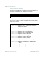
Typographic Conventions
The following table describes the typographic styles used in this book.
Table 1 Typographic Conventions
Typeface or
Symbol
Meaning
Example
AaBbCc123
This type is used for names of commands,
files, and directories used within the text.
View the readme.txt file.
It also depicts on-screen computer output
and prompts.
Main#
AaBbCc123
Main# sys
This bold type appears in command
examples. It shows text that must be typed
in exactly as shown.
<AaBbCc123
>
To establish a Telnet session, enter:
This italicized type appears in command
host# telnet <IP address>
examples as a parameter place holder.
Replace the indicated text with the
appropriate real name or value when using
the command. Do not type the brackets.
This also shows book titles, special terms,
or words to be emphasized.
[ ]
BMD00136, November 2009
Read your User’s Guide thoroughly.
Command items shown inside brackets are host# ls [-a]
optional and can be used or excluded as the
situation demands. Do not type the
brackets.
: Preface 13
BLADE OS 5.1 Application Guide
How to Get Help
If you need help, service, or technical assistance, call BLADE Network Technologies Technical
Support:
US toll free calls: 1-800-414-5268
International calls: 1-408-834-7871
You also can visit our web site at the following address:
http://www.bladenetwork.net
Click the Support tab.
The warranty card received with your product provides details for contacting a customer
support representative. If you are unable to locate this information, please contact your reseller.
Before you call, prepare the following information:
14 : Preface
Serial number of the switch unit
Software release version number
Brief description of the problem and the steps you have already taken
Technical support dump information (# show tech-support)
BMD00136, November 2009
CHAPTER 1
Accessing the Switch
The Blade OS software provides means for accessing, configuring, and viewing information and
statistics about the RackSwitch G8000. This chapter discusses different methods of accessing the
switch and ways to secure the switch for remote administrators:
“Configuring an IP Interface” on page 15
“Using Telnet” on page 17
“Using the Browser-Based Interface” on page 19
“Using SNMP” on page 22
“Securing Access to the Switch” on page 27
“RADIUS Authentication and Authorization” on page 27
“TACACS+ Authentication” on page 31
“End User Access Control” on page 38
Configuring an IP Interface
To manage the switch using Telnet, SNMP, or a Web browser, you must configure an IP interface.
Following are the factory default settings for IP interface 1:
IP address: 192.168.1.211
Mask:
255.255.255.0)
DHCP:
enabled
When DHCP is enabled, a DHCP server configured in the local network for the switch configures
the interface. If the switch fails to renew the address obtained through DHCP, it uses the factory
configuration address.
If you manually configure a static IP address, DHCP is disabled. If you manually enable DHCP, the
interface will be configured by the DHCP server.
BMD00136, November 2009
15
BLADE OS 5.1 Application Guide
To access the switch, the following IP parameters must be configured:
IP address
Subnet mask
Default gateway address
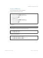
1. Log on to the switch.
2. Enter IP interface mode.
RS G8000> enable
RS G8000# configure terminal
RS G8000 (config)# interface ip 1
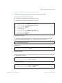
3. Configure an IP interface, subnet mask, and VLAN assignment. Enable the interface.
RS
RS
RS
RS
RS
G8000
G8000
G8000
G8000
G8000
(config-ip-if)#
(config-ip-if)#
(config-ip-if)#
(config-ip-if)#
(config-ip-if)#
ip address 10.10.10.2
ip netmask 255.255.255.0
vlan 1
enable
exit
(example IP address)
4. Configure the default gateway. Enable the gateway.
RS G8000 (config)# ip gateway address 10.10.10.1
RS G8000 (config)# ip gateway enable
(example gateway address)
Once you configure the IP address for your switch and you have an existing network
connection, you can use the Telnet program from an external management station to access and
control the switch.
The G8000 supports a command-line interface (CLI) that you can use to configure and control the
switch over the network using the Telnet program. You can use the CLI to perform many basic
network management functions. In addition, you can configure the switch for management using an
SNMP-based network management system or a Web browser.
For more information about using the CLI, refer to the RackSwitch G8000
Command Reference.
16 Chapter 1: Accessing the Switch
BMD00136, November 2009
BLADE OS 5.1 Application Guide
Using Telnet
A Telnet connection offers the convenience of accessing the switch from any workstation connected
to an interface port. Telnet access provides the same options for user access and administrator
access as those available through the console port.
To configure the switch for Telnet access, the switch must have an IP address. The switch can get its
IP address in one of two ways:
Dynamically, from a DHCP server on your network (available only for IP interface 1)
Manually, when you configure the switch IP address
Once you have configured the switch with an IP address and gateway, you can access the switch
from any workstation connected to the management network. Telnet access provides the same
options for user and administrator access as those available through the console port.
By default, Telnet access is enabled. Use the following command to disable/enable Telnet access:
RS G8000 (config)# [no] access telnet enable
To establish a Telnet connection to the switch, you can run the Telnet program on your workstation
and issue the Telnet command, followed by the switch IP address:
telnet <switch IP address>
BOOTP Relay Agent
BOOTP Relay Agent Overview
The G8000 can function as a Bootstrap Protocol relay agent, enabling the switch to forward a client
request for an IP address up to two BOOTP servers with IP addresses that have been configured on
the switch.
When a switch receives a BOOTP request from a BOOTP client requesting an IP address, the
switch acts as a proxy for the client. The request is then forwarded as a UDP Unicast MAC layer
message to two BOOTP servers whose IP addresses are configured on the switch. The servers
respond to the switch with a Unicast reply that contains the default gateway and IP address for the
client. The switch then forwards this reply back to the client.
BMD00136, November 2009
Chapter 1: Accessing the Switch 17
BLADE OS 5.1 Application Guide
BOOTP Relay Agent Configuration
To enable the G8000 to be the BOOTP forwarder, you need to configure the BOOTP server IP
addresses on the switch, and enable BOOTP relay on the interface(s) on which the BOOTP requests
are received.
Generally, you should configure the command on the switch IP interface that is closest to the client,
so that the BOOTP server knows from which IP subnet the newly allocated IP address should come.
Use the following commands to configure the switch as a BOOTP relay agent:
>> # ip bootp-relay server1 <IP address>
>> # ip bootp-relay server2 <IP address>
>> # ip bootp-relay enable
Use the following command to enable the Relay functionality on an IP interface:
>> # interface ip <interface number>
>> (config-ip-if)# relay
DHCP Relay Agent
DHCP Relay Agent Overview
DHCP is described in RFC 2131, and the DHCP relay agent supported on the G8000 is described in
RFC 1542. DHCP uses UDP as its transport protocol. The client sends messages to the server on
port 67 and the server sends messages to the client on port 68.
DHCP defines the methods through which clients can be assigned an IP address for a finite lease
period and allowing reassignment of the IP address to another client later. Additionally, DHCP
provides the mechanism for a client to gather other IP configuration parameters it needs to operate
in the TCP/IP network.
In the DHCP environment, the switch acts as a relay agent. The DHCP relay feature enables the
switch to forward a client request for an IP address to two BOOTP servers with IP addresses that
have been configured on the switch.
When a switch receives a UDP broadcast on port 67 from a DHCP client requesting an IP address,
the switch acts as a proxy for the client, replacing the client source IP (SIP) and destination IP (DIP)
addresses. The request is then forwarded as a UDP Unicast MAC layer message to two BOOTP
servers whose IP addresses are configured on the switch. The servers respond as a a UDP Unicast
message back to the switch, with the default gateway and IP address for the client. The destination
IP address in the server response represents the interface address on the switch that received the
client request. This interface address tells the switch on which VLAN to send the server response to
the client.
18 Chapter 1: Accessing the Switch
BMD00136, November 2009
BLADE OS 5.1 Application Guide
DHCP Relay Agent Configuration
To enable the G8000 to be the BOOTP forwarder, you need to configure the DHCP/BOOTP server
IP addresses on the switch. Generally, you should configure the switch IP interface on the client side
to match the client’s subnet, and configure VLANs to separate clients and server subnets. The
DHCP server knows from which IP subnet the newly allocated IP address should come.
In G8000 implementation, there is no need for primary or secondary servers. The client request is
forwarded to the BOOTP servers configured on the switch. The use of two servers provide failover
redundancy. However, no health checking is supported.
Use the following commands to configure the switch as a DHCP relay agent:
>> # ip bootp-relay server1 <IP address>
>> # ip bootp-relay server2 <IP address>
>> # ip bootp-relay enable
Additionally, DHCP Relay functionality can be assigned on a per interface basis. Use the following
command to enable the Relay functionality:
>> # interface ip <interface number>
>> (config-ip-if)# relay
Using the Browser-Based Interface
The Browser-Based Interface (BBI) is a Web-based management interface for interactive switch
access through your Web browser.
The BBI provides access to the common configuration, management and operation features of the
switch through your Web browser. For more information, refer to the RackSwitch G8000 BBI Quick
Guide.
Configuring BBI access via HTTP
By default, BBI access via HTTP is enabled. Use the following command to disable/enable BBI
access on the switch via HTTP:
RS G8000 (config)# access http enable
The default HTTP web server port to access the BBI is port 80. However, you can change the
default Web server port with the following command:
RS G8000 (config)# access http port <TCP port number>
BMD00136, November 2009
Chapter 1: Accessing the Switch 19
BLADE OS 5.1 Application Guide
For workstation access to your switch via the BBI, open a Web browser window and type in the
URL using the IP interface address of the switch, such as:
http://10.10.10.1
Configuring BBI access via HTTPS
The BBI can also be accessed via a secure HTTPS connection over interface ports.
1. Enable HTTPS
By default, BBI access via HTTPS is disabled on the switch. To enable BBI Access via HTTPS, use
the following command:
>> # access https enable
2. Set the HTTPS server port number (optional)
To change the HTTPS Web server port number from the default port 443, use the following
command:
>> # access https port <x>
3. Use the apply and save commands to activate and store the configuration changes.
4. Generate the HTTPS certificate.
Accessing the BBI via HTTPS requires that you generate a certificate to be used during the key
exchange. A default certificate is created the first time HTTPS is enabled, but you can create a new
certificate defining the information you want to be used in the various fields.
>> access https generate-certificate
Country Name (2 letter code) []: <country code>
State or Province Name (full name) []: <state>
Locality Name (eg, city) []: <city>
Organization Name (eg, company) []: <company>
Organizational Unit Name (eg, section) []: <org. unit>
Common Name (eg, YOUR name) []: <name>
Email (eg, email address) []: <email address>
Confirm generating certificate? [y/n]: y
Generating certificate. Please wait (approx 30 seconds)
restarting SSL agent
5. Save the HTTPS certificate.
The certificate is valid only until the switch is rebooted. In order to save the certificate so that it is
retained beyond reboot or power cycles, use the following command:
>> # access https save-certificate
20 Chapter 1: Accessing the Switch
BMD00136, November 2009
BLADE OS 5.1 Application Guide
When a client (e.g. web browser) connects to the switch, the client is asked to accept the certificate
and verify that the fields match what is expected. Once BBI access is granted to the client, the BBI
can be used as described in the RackSwitch G8000 BBI Quick Guide.
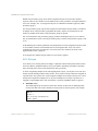
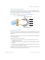
The BBI is organized at a high level as follows:
Context buttons – These buttons allow you to select the type of action you wish to perform. The
Configuration button provides access to the configuration elements for the entire switch. The
Statistics button provides access to the switch statistics and state information. The Dashboard
button allows you to display settings and operating status of a variety of switch features.
Navigation Window – This window provides a menu list of switch features and functions,
as follows:
System – Access the configuration elements for the entire switch.
Switch Ports – Configure each of the physical ports on the switch.
Port-Based Port Mirroring – Configure port mirroring.
Layer 2 Management – Configure Layer 2 features, such as VLANs and Spanning Tree
Layer 3 Management – Configure Layer 3 features, such as IP interfaces and gateway.
QoS – Configure Quality of Service (QoS) features for the switch.
Access Control – Configure Access Control Lists to filter IP packets.
BMD00136, November 2009
Chapter 1: Accessing the Switch 21
BLADE OS 5.1 Application Guide
Using SNMP
Blade OS provides SNMP v1.0 and SNMP v3.0 support for access through any network
management software, such as IBM Director or HP-OpenView.
SNMP v1, v2
To access the SNMP agent on the G8000, the read and write community strings on the SNMP
manager should be configured to match those on the switch. The default read community string on
the switch is public and the default write community string is private.
The read and write community strings on the switch can be changed using the following commands
on the CLI:
RS G8000 (config)# snmp-server read-community <1-32 characters>
and
RS G8000 (config)# snmp-server write-community <1-32 characters>
The SNMP manager should be able to reach any one of the IP interfaces on the switch.
SNMP v3.0
SNMPv3 is an enhanced version of the Simple Network Management Protocol, approved by the
Internet Engineering Steering Group in March, 2002. SNMP v3.0 contains additional security and
authentication features that provide data origin authentication, data integrity checks, timeliness
indicators and encryption to protect against threats such as masquerade, modification of
information, message stream modification and disclosure.
SNMPv3 ensures that the client can use SNMPv3 to query the MIBs, mainly for security.
For more information on SNMP MIBs and the commands used to configure SNMP on the switch,
see the RackSwitch G8000 Command Reference.
Default Configuration
The G8000 has two SNMP v3 users by default. Both of the following users have access to all the
MIBs supported by the switch:
1) username 1: adminmd5 (password adminmd5). Authentication used is MD5.
2) username 2: adminsha (password adminsha). Authentication used is SHA.
22 Chapter 1: Accessing the Switch
BMD00136, November 2009
BLADE OS 5.1 Application Guide
To configure an SNMP user name, enter the following command:
RS G8000 (config)# snmp-server user <1-16> name <1-32>
User Configuration:
Users can be configured to use the authentication/privacy options. The G8000 supports two
authentication algorithms: MD5 and SHA, as specified in the following command:
snmp-server user <1-16> authentication-protocol md5|sha
1. To configure a user with name 'admin,' authentication type MD5, and authentication password of
'admin,' privacy option DES with privacy password of 'admin,' use the following CLI commands.
RS G8000 (config)# snmp-server user 5 name admin
RS G8000 (config)# snmp-server user 5 authentication-protocol md5
authentication-password
Changing authentication password; validation required:
Enter current admin password:
<admin. password>
Enter new authentication password:
<auth. password>
Re-enter new authentication password:
<auth. password>
New authentication password accepted.
RS G8000 (config)# snmp-server user 5 privacy-protocol des
privacy-password
Changing privacy password; validation required:
Enter current admin password:
<admin. password>
Enter new privacy password:
<privacy password>
Re-enter new privacy password:
<privacy password>
New privacy password accepted.
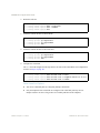
2. Configure a user access group, along with the views the group may access. Use the access table to
configure the group’s access level.
RS
RS
RS
RS
RS
G8000
G8000
G8000
G8000
G8000
(config)#
(config)#
(config)#
(config)#
(config)#
snmp-server
snmp-server
snmp-server
snmp-server
snmp-server
access
access
access
access
access
5
5
5
5
5
name admingrp
level authpriv
read-view iso
write-view iso
notify-view iso
Because the read view, write view, and notify view are all set to “iso,” the user type has access to all
private and public MIBs.
3. Assign the user to the user group. Use the group table to link the user to a particular access group.
RS G8000 (config)# snmp-server group 5 user-name admin
RS G8000 (config)# snmp-server group 5 group-name admingrp
BMD00136, November 2009
Chapter 1: Accessing the Switch 23
BLADE OS 5.1 Application Guide
Configuring SNMP Trap Hosts
SNMPv1 Trap Host Configuration
1. Configure a user with no authentication and password.
RS G8000 (config)# snmp-server user 10 name v1trap
2. Configure an access group and group table entries for the user.
RS
RS
RS
RS
RS
RS
G8000
G8000
G8000
G8000
G8000
G8000
(config)#
(config)#
(config)#
(config)#
(config)#
(config)#
snmp-server
snmp-server
snmp-server
snmp-server
snmp-server
snmp-server
group 10 security snmpv1
group 10 user-name v1trap
group 10 group-name v1trap
access 10 name v1trap
access 10 security snmpv1
access 10 notify-view iso
3. Configure an entry in the notify table.
RS G8000 (config)# snmp-server notify 10 name v1trap
RS G8000 (config)# snmp-server notify 10 tag v1trap
4. Specify the IP address and other trap parameters in the targetAddr and targetParam tables.
RS G8000 (config)# snmp-server target-address 10
address 100.10.2.1
RS G8000 (config)# snmp-server target-address 10
RS G8000 (config)# snmp-server target-address 10
v1param
RS G8000 (config)# snmp-server target-parameters
RS G8000 (config)# snmp-server target-parameters
RS G8000 (config)# snmp-server target-parameters
RS G8000 (config)# snmp-server target-parameters
name v1trap
taglist v1trap
parameters-name
10
10
10
10
name v1param
message snmpv1
user-name v1trap
security snmpv1
5. Use the community table to specify which community string is used in the trap.
RS G8000 (config)# snmp-server community 10 index v1trap
RS G8000 (config)# snmp-server community 10 user-name v1trap
24 Chapter 1: Accessing the Switch
BMD00136, November 2009
BLADE OS 5.1 Application Guide
SNMPv2 Trap Host Configuration
The SNMPv2 trap host configuration is similar to the SNMPv1 trap host configuration.
Wherever you specify the model, use snmpv2 instead of snmpv1.
RS G8000 (config)# snmp-server user 10 name v2trap
RS
RS
RS
RS
RS
RS
G8000
G8000
G8000
G8000
G8000
G8000
(config)#
(config)#
(config)#
(config)#
(config)#
(config)#
snmp-server
snmp-server
snmp-server
snmp-server
snmp-server
snmp-server
group 10 security snmpv2
group 10 user-name v2trap
group 10 group-name v2trap
access 10 name v2trap
access 10 security snmpv2
access 10 notify-view iso
RS G8000 (config)# snmp-server notify 10 name v2trap
RS G8000 (config)# snmp-server notify 10 tag v2trap
RS G8000 (config)# snmp-server target-address 10
address 100.10.2.1
RS G8000 (config)# snmp-server target-address 10
RS G8000 (config)# snmp-server target-address 10
v2param
RS G8000 (config)# snmp-server target-parameters
RS G8000 (config)# snmp-server target-parameters
RS G8000 (config)# snmp-server target-parameters
RS G8000 (config)# snmp-server target-parameters
name v2trap
taglist v2trap
parameters-name
10
10
10
10
name v2param
message snmpv2c
user-name v2trap
security snmpv2
RS G8000 (config)# snmp-server community 10 index v2trap
RS G8000 (config)# snmp-server community 10 user-name v2trap
BMD00136, November 2009
Chapter 1: Accessing the Switch 25
BLADE OS 5.1 Application Guide
SNMPv3 Trap Host Configuration
To configure a user for SNMPv3 traps, you can choose to send the traps with both privacy and
authentication, with authentication only, or without privacy or authentication.
This is configured in the access table using the following commands:
RS G8000 (config)# snmp-server access <1-32> level
RS G8000 (config)# snmp-server target-parameters <1-16>
Configure the user in the user table accordingly.
It is not necessary to configure the community table for SNMPv3 traps because the community
string is not used by SNMPv3.
The following example shows how to configure a SNMPv3 user v3trap with authentication only:
RS G8000 (config)# snmp-server user 11 name v3trap
RS G8000 (config)# snmp-server user 11 authentication-protocol md5
authentication-password
Changing authentication password; validation required:
Enter current admin password:
<admin. password>
Enter new authentication password:
<auth. password>
Re-enter new authentication password:
<auth. password>
New authentication password accepted.
RS
RS
RS
RS
RS
G8000
G8000
G8000
G8000
G8000
(config)#
(config)#
(config)#
(config)#
(config)#
snmp-server
snmp-server
snmp-server
snmp-server
snmp-server
group 11 user-name v3trap
group 11 group-name v3trap
access 11 name v3trap
access 11 level authNoPriv
access 11 notify-view iso
RS G8000 (config)# snmp-server notify 11 name v3trap
RS G8000 (config)# snmp-server notify 11 tag v3trap
RS G8000 (config)# snmp-server target-address 11 name v2trap
address 100.10.2.1
RS G8000 (config)# snmp-server target-address 11 taglist v3trap
RS G8000 (config)# snmp-server target-address 11 parameters-name
v3param
RS G8000 (config)# snmp-server target-parameters 11 name v3param
RS G8000 (config)# snmp-server target-parameters 11 user-name v3trap
RS G8000 (config)# snmp-server target-parameters 11 level authNoPriv
26 Chapter 1: Accessing the Switch
BMD00136, November 2009
BLADE OS 5.1 Application Guide
Securing Access to the Switch
Secure switch management is needed for environments that perform significant management
functions across the Internet.
The following features are addressed in this section:
“RADIUS Authentication and Authorization” on page 27
“TACACS+ Authentication” on page 31
“LDAP Authentication and Authorization” on page 34
“Secure Shell” on page 36
“End User Access Control” on page 38
RADIUS Authentication and Authorization
Blade OS supports the RADIUS (Remote Authentication Dial-in User Service) method to
authenticate and authorize remote administrators for managing the switch. This method is based on
a client/server model. The Remote Access Server (RAS)—the switch—is a client to the back-end
database server. A remote user (the remote administrator) interacts only with the RAS, not the
back-end server and database.
RADIUS authentication consists of the following components:
A protocol with a frame format that utilizes UDP over IP (based on RFC 2138 and 2866)
A centralized server that stores all the user authorization information
A client, in this case, the switch
The G8000—acting as the RADIUS client—communicates to the RADIUS server to authenticate
and authorize a remote administrator using the protocol definitions specified in RFC 2138 and
2866. Transactions between the client and the RADIUS server are authenticated using a shared key
that is not sent over the network. In addition, the remote administrator passwords are sent encrypted
between the RADIUS client (the switch) and the back-end RADIUS server.
BMD00136, November 2009
Chapter 1: Accessing the Switch 27
BLADE OS 5.1 Application Guide
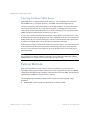
How RADIUS Authentication Works
1.
Remote administrator connects to the switch and provides user name and password.
2.
Using Authentication/Authorization protocol, the switch sends request to authentication server.
3.
Authentication server checks the request against the user ID database.
4.
Using RADIUS protocol, the authentication server instructs the switch to grant or deny
administrative access.
Configuring RADIUS
Use the following procedure to configure RADIUS authentication on your switch.
1.
Configure the Primary and Secondary RADIUS servers, and enable RADIUS
authentication.
RS G8000 (config)# radius-server primary-host 10.10.1.1
RS G8000 (config)# radius-server secondary-host 10.10.1.2
RS G8000 (config)# radius-server enable
2.
Configure the RADIUS secret and enable the feature.
RS G8000 (config)# radius-server primary-host 10.10.1.1
key <1-32 character secret>
RS G8000 (config)# radius-server secondary-host 10.10.1.2
key <1-32 character secret>
3.
If desired, you may change the default UDP port number used to listen to RADIUS.
The well-known port for RADIUS is 1812.
RS G8000 (config)# radius-server port <UDP port number>
4.
Configure the number retry attempts for contacting the RADIUS server, and the timeout period.
RS G8000 (config)# radius-server retransmit 3
RS G8000 (config)# radius-server timeout 5
28 Chapter 1: Accessing the Switch
BMD00136, November 2009
BLADE OS 5.1 Application Guide
RADIUS Authentication Features in Blade OS
Blade OS supports the following RADIUS authentication features:
Supports RADIUS client on the switch, based on the protocol definitions in RFC 2138 and
RFC 2866.
Allows RADIUS secret password up to 32 bytes and less than 16 octets.
Supports secondary authentication server so that when the primary authentication server is
unreachable, the switch can send client authentication requests to the secondary authentication
server. Use the following command to show the currently active RADIUS authentication
server:
RS G8000 (config)# show radius-server
Supports user-configurable RADIUS server retry and time-out values:
Time-out value = 1-10 seconds
Retries = 1-3
The switch will time out if it does not receive a response from the RADIUS server in 1-3
retries. The switch will also automatically retry connecting to the RADIUS server before it
declares the server down.
Supports user-configurable RADIUS application port.
The default is 1812/UDP-based on RFC 2138. Port 1645 is also supported.
Allows network administrator to define privileges for one or more specific users to access the
switch at the RADIUS user database.
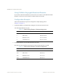
Switch User Accounts
The user accounts listed in Table 2 can be defined in the RADIUS server dictionary file.
Table 2 User Access Levels
User Account
Description and Tasks Performed
User
The User has no direct responsibility for switch management. user
He/she can view all switch status information and statistics
but cannot make any configuration changes to the switch.
BMD00136, November 2009
Password
Chapter 1: Accessing the Switch 29
BLADE OS 5.1 Application Guide
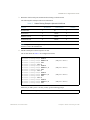
Table 2 User Access Levels
User Account
Description and Tasks Performed
Password
Operator
The Operator manages all functions of the switch. The
Operator can reset ports.
oper
Administrator
admin
The super-user Administrator has complete access to all
commands, information, and configuration commands on the
switch, including the ability to change both the user and
operator passwords.
RADIUS Attributes for G8000 User Privileges
When the user logs in, the switch authenticates his/her level of access by sending the RADIUS
access request, that is, the client authentication request, to the RADIUS authentication server.
If the remote user is successfully authenticated by the authentication server, the switch will verify
the privileges of the remote user and authorize the appropriate access. The administrator has an
option to allow secure backdoor access via Telnet/SSH/BBI. Secure backdoor provides switch
access when the RADIUS servers cannot be reached. You always can access the switch via the
console port, by using noradius and the administrator password, whether secure backdoor is
enabled or not.
Note – To obtain the RADIUS backdoor password for your G8000, contact Technical Support.
All user privileges, other than those assigned to the Administrator, have to be defined in the
RADIUS dictionary. RADIUS attribute 6 which is built into all RADIUS servers defines the
administrator. The file name of the dictionary is RADIUS vendor-dependent. The following
RADIUS attributes are defined for G8000 user privileges levels:
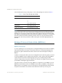
Table 3 Blade OS-proprietary Attributes for RADIUS
User Name/Access
User-Service-Type
Value
User
Vendor-supplied
255
Operator
Vendor-supplied
252
Admin
Vendor-supplied
6
30 Chapter 1: Accessing the Switch
BMD00136, November 2009
BLADE OS 5.1 Application Guide
TACACS+ Authentication
Blade OS supports authentication and authorization with networks using the Cisco Systems
TACACS+ protocol. The G8000 functions as the Network Access Server (NAS) by interacting with
the remote client and initiating authentication and authorization sessions with the TACACS+ access
server. The remote user is defined as someone requiring management access to the G8000 through
a data port.
TACACS+ offers the following advantages over RADIUS:
TACACS+ uses TCP-based connection-oriented transport; whereas RADIUS is UDP-based.
TCP offers a connection-oriented transport, while UDP offers best-effort delivery. RADIUS
requires additional programmable variables such as re-transmit attempts and time-outs to
compensate for best-effort transport, but it lacks the level of built-in support that a TCP
transport offers.
TACACS+ offers full packet encryption whereas RADIUS offers password-only encryption in
authentication requests.
TACACS+ separates authentication, authorization and accounting.
How TACACS+ Authentication Works
TACACS+ works much in the same way as RADIUS authentication as described on page 27.
1.
Remote administrator connects to the switch and provides user name and password.
2.
Using Authentication/Authorization protocol, the switch sends request to authentication server.
3.
Authentication server checks the request against the user ID database.
4.
Using TACACS+ protocol, the authentication server instructs the switch to grant or deny
administrative access.
During a session, if additional authorization checking is needed, the switch checks with a
TACACS+ server to determine if the user is granted permission to use a particular command.
TACACS+ Authentication Features in Blade OS
Authentication is the action of determining the identity of a user, and is generally done when the
user first attempts to log in to a device or gain access to its services. Blade OS supports ASCII
inbound login to the device. PAP, CHAP and ARAP login methods, TACACS+ change password
requests, and one-time password authentication are not supported.
BMD00136, November 2009
Chapter 1: Accessing the Switch 31
BLADE OS 5.1 Application Guide
Authorization
Authorization is the action of determining a user’s privileges on the device, and usually takes place
after authentication.
The default mapping between TACACS+ authorization levels and Blade OS management access
levels is shown in Table 4. The authorization levels must be defined on the TACACS+ server.
Table 4
Default TACACS+ Authorization Levels
Blade OS User Access Level
TACACS+ level
user
0
oper
3
admin
6
Alternate mapping between TACACS+ authorization levels and Blade OS management access
levels is shown in Table 5. Use the following command to set the alternate TACACS+ authorization
levels.
RS G8000 (config)# tacacs-server privilege-mapping
Table 5
Alternate TACACS+ Authorization Levels
Blade OS User Access Level
TACACS+ level
user
0-1
oper
6-8
admin
14 - 15
If the remote user is successfully authenticated by the authentication server, the switch
verifies the privileges of the remote user and authorizes the appropriate access. The administrator
has an option to allow secure backdoor access via Telnet/SSH. Secure backdoor provides switch
access when the TACACS+ servers cannot be reached. You always can access the switch via the
console port, by using notacacs and the administrator password, whether secure backdoor is
enabled or not.
Note – To obtain the TACACS+ backdoor password for your G8000, contact
Technical Support.
32 Chapter 1: Accessing the Switch
BMD00136, November 2009
BLADE OS 5.1 Application Guide
Accounting
Accounting is the action of recording a user's activities on the device for the purposes of billing
and/or security. It follows the authentication and authorization actions. If the authentication and
authorization is not performed via TACACS+, there are no TACACS+ accounting messages sent
out.
You can use TACACS+ to record and track software logins, configuration changes, and interactive
commands.
The G8000 supports the following TACACS+ accounting attributes:
protocol (console/Telnet/SSH/HTTP/HTTPS)
start_time
stop_time
elapsed_time
disc_cause
Note – When using the Browser-Based Interface, the TACACS+ Accounting Stop records are sent
only if the Logout button on the browser is clicked.
Command Authorization and Logging
When TACACS+ Command Authorization is enabled, Blade OS configuration commands are sent
to the TACACS+ server for authorization. Use the following command to enable TACACS+
Command Authorization:
RS G8000 (config)# tacacs-server command-authorization
When TACACS+ Command Logging is enabled, Blade OS configuration commands are
logged on the TACACS+ server. Use the following command to enable TACACS+
Command Logging:
RS G8000 (config)# tacacs-server command-logging
The following examples illustrate the format of Blade OS commands sent to the TACACS+ server:
authorization request, cmd=shell, cmd-arg=interface ip
accounting request, cmd=shell, cmd-arg=interface ip
authorization request, cmd=shell, cmd-arg=enable
accounting request, cmd=shell, cmd-arg=enable
BMD00136, November 2009
Chapter 1: Accessing the Switch 33
BLADE OS 5.1 Application Guide
Configuring TACACS+ Authentication
1. Configure the Primary and Secondary TACACS+ servers, and enable TACACS
authentication.
RS G8000 (config)# tacacs-server primary-host 10.10.1.1
RS G8000 (config)# tacacs-server secondary-host 10.10.1.2
RS G8000 (config)# tacacs-server enable
2. Configure the TACACS+ secret and second secret.
RS G8000 (config)# tacacs-server primary-host 10.10.1.1
key <1-32 character secret>
RS G8000 (config)# tacacs-server secondary-host 10.10.1.2
key <1-32 character secret>
3. If desired, you may change the default TCP port number used to listen to TACACS+.
The well-known port for TACACS+ is 49.
RS G8000 (config)# tacacs-server port <TCP port number>
4. Configure the number of retry attempts, and the timeout period.
RS G8000 (config)# tacacs-server retransmit 3
RS G8000 (config)# tacacs-server timeout 5
LDAP Authentication and Authorization
BLADE OS supports the LDAP (Lightweight Directory Access Protocol) method to authenticate
and authorize remote administrators to manage the switch. LDAP is based on a client/server model.
The switch acts as a client to the LDAP server. A remote user (the remote administrator) interacts
only with the switch, not the back-end server and database.
LDAP authentication consists of the following components:
A protocol with a frame format that utilizes TCP over IP
A centralized server that stores all the user authorization information
A client, in this case, the switch
Each entry in the LDAP server is referenced by its Distinguished Name (DN). The DN consists of
the user-account name concatenated with the LDAP domain name. If the user-account name is
John, the following is an example DN:
uid=John,ou=people,dc=domain,dc=com
34 Chapter 1: Accessing the Switch
BMD00136, November 2009
BLADE OS 5.1 Application Guide
Configuring the LDAP Server
G8000 user groups and user accounts must reside within the same domain. On the LDAP server,
configure the domain to include G8000 user groups and user accounts, as follows:
User Accounts:
Use the uid attribute to define each individual user account.
User Groups:
Use the members attribute in the groupOfNames object class to create the user groups. The first
word of the common name for each user group must be equal to the user group names defined
in the G8000, as follows:
admin
oper
user
Configuring LDAP Authentication on the Switch
1. Turn LDAP authentication on, then configure the Primary and Secondary LDAP servers.
>> # ldap-server enable
>> # ldap-server primary-host 10.10.1.1
>> # ldap-server secondary-host 10.10.1.2
2. Configure the domain name.
>> # ldap-server domain ou=people,dc=mydomain,dc=com
3. If desired, you may change the default TCP port number used to listen to LDAP.
The well-known port for LDAP is 389.
>> # ldap-server port <1-65000>
4. Configure the number of retry attempts for contacting the LDAP server, and the timeout period.
>> # ldap-server retransmit <1-3>
>> # ldap-server timeout <4-15>
BMD00136, November 2009
Chapter 1: Accessing the Switch 35
BLADE OS 5.1 Application Guide
Secure Shell
Secure Shell (SSH) use secure tunnels to encrypt and secure messages between a remote
administrator and the switch. Telnet does not provide this level of security. The Telnet method of
managing a G8000 does not provide a secure connection.
SSH is a protocol that enables remote administrators to log securely into the G8000 over a
network to execute management commands.
The benefits of using SSH are listed below:
Authentication of remote administrators
Identifying the administrator using Name/Password
Authorization of remote administrators
Determining the permitted actions and customizing service for individual administrators
Encryption of management messages
Encrypting messages between the remote administrator and switch
The Blade OS implementation of SSH supports both versions 1.0 and 2.0 and supports
SSH client versions 1.5 - 2.x.
Configuring SSH Features on the Switch
Before you can use SSH commands, use the following commands to turn on SSH.
SSH is disabled by default.
Use the following command to enable SSH:
RS G8000 (config)# ssh enable
SSH Encryption of Management Messages
The following encryption and authentication methods are supported for SSH:
Server Host Authentication:
Client RSA authenticates the switch at the beginning of every
connection
Key Exchange:
RSA
Encryption:
3DES-CBC, DES
User Authentication:
Local password authentication
36 Chapter 1: Accessing the Switch
BMD00136, November 2009
BLADE OS 5.1 Application Guide
Generating RSA Host and Server Keys for SSH Access
To support the SSH server feature, two sets of RSA keys (host and server keys) are required. The
host key is 1024 bits and is used to identify the G8000. The server key is 768 bits and is used to
make it impossible to decipher a captured session by breaking into the G8000 at a later time.
When the SSH server is first enabled and applied, the switch automatically generates the RSA host
and server keys and is stored in the Flash memory. To configure RSA host and server keys, enter the
following commands to generate them manually.
RS G8000 (config)# ssh generate-host-key
RS G8000 (config)# ssh generate-server-key
When the switch reboots, it will retrieve the host and server keys from the Flash memory.
If these two keys are not available in the flash and if the SSH server feature is enabled, the switch
automatically generates them during the system reboot. This process may take several minutes to
complete.
The switch can automatically regenerate the RSA server key. To set the interval of RSA server key
autogeneration, use the following command:
RS G8000 (config)# ssh interval <number of hours (0-24)>
A value of 0 (zero) denotes that RSA server key autogeneration is disabled. When greater
than 0, the switch will autogenerate the RSA server key every specified interval; however, RSA
server key generation is skipped if the switch is busy doing other key or cipher generation when the
timer expires.
Note – The switch will perform only one session of key/cipher generation at a time. Thus, an SSH
client will not be able to log in if the switch is performing key generation at that time, or if another
client has logged in immediately prior. Also, key generation will fail if an SSH client is logging in
at that time.
SSH Integration with RADIUS/TACACS+ Authentication
SSH is integrated with RADIUS authentication. After the RADIUS server is enabled on the switch,
all subsequent SSH authentication requests will be redirected to the specified RADIUS servers for
authentication. The redirection is transparent to the SSH clients.
SSH is integrated with TACACS+ authentication. After the TACACS+ server is enabled on the
switch, all subsequent SSH authentication requests will be redirected to the specified TACACS+
servers for authentication. The redirection is transparent to the SSH clients.
BMD00136, November 2009
Chapter 1: Accessing the Switch 37
BLADE OS 5.1 Application Guide
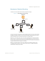
End User Access Control
BLADE OS allows an administrator to define end user accounts that permit end users to perform
operation tasks via the switch CLI commands. Once end user accounts are configured and enabled,
the switch requires username/password authentication.
For example, an administrator can assign a user, who can then log into the switch and perform
operational commands (effective only until the next switch reboot).
Considerations for Configuring End User Accounts
A maximum of 10 user IDs are supported on the switch.
BLADE OS supports end user support for Console, Telnet, BBI, and SSHv1/v2 access to the
switch.
If RADIUS authentication is used, the user password on the Radius server will override the
user password on the G8000. Also note that the password change command on the switch only
modifies the use switch password and has no effect on the user password on the Radius server.
Radius authentication and user password cannot be used concurrently to access the switch.
Passwords can be up to 128 characters in length for TACACS, RADIUS, Telnet, SSH, Console,
and Web access.
Strong Passwords
The administrator can require use of Strong Passwords for users to access the G8000. Strong
Passwords enhance security because they make password guessing more difficult.
The following rules apply when Strong Passwords are enabled:
Each passwords must be 8 to 14 characters
Within the first 8 characters, the password:
must have at least one number or one symbol
must have both upper and lower case letters
cannot be the same as any four previously used passwords
The following are examples of strong passwords:
1234AbcXyz
Super+User
Exo1cet2
The administrator can choose the number of days allowed before each password expires. When a
strong password expires, the user is allowed to log in one last time (last time) to change the
password. A warning provides advance notice for users to change the password.
38 Chapter 1: Accessing the Switch
BMD00136, November 2009
BLADE OS 5.1 Application Guide
Use the Strong Password commands to configure Strong Passwords.
>> # access user strong-password enable
User Access Control
Use the end user access control commands to configure user IDs.
Setting Up User IDs, User Names, and Passwords
Up to 10 user IDs can be configured. Define each user name and password.
>> # access user 1 name <new user name>
>> # access user 1 password <new user password>
Defining a User’s Access Level
The end user is by default assigned to the user access level (also known as class of service, or CoS).
CoS for all user accounts have global access to all resources except for User CoS, which has access
to view only resources that the user owns. For more information, see Table 2 on page 29.
To change the user’s level, enter the class of service cos command, and select one of the following
options:
>> # access user 1 level {user|oper|admin}
Validating a User’s Configuration
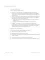
>> # show access user uid 1
Enabling or Disabling a User
An end user account must be enabled before the switch recognizes and permits login under the
account. Once enabled, the switch requires any user to enter both username and password.
>> # access user 1 enable
>> # no access user 1 enable
BMD00136, November 2009
Chapter 1: Accessing the Switch 39
BLADE OS 5.1 Application Guide
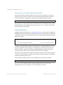
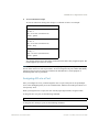
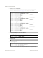
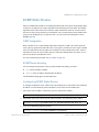
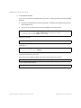
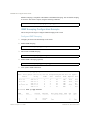
Listing Current Users
The cur command displays defined user accounts and whether or not each user is currently logged
into the switch.
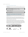
>> # show access user
Usernames:
user
- Enabled - offline
oper
- Disabled - offline
admin
- Always Enabled - online 1 session
Current User ID table:
1: name jane
, ena, cos user
2: name john
, ena, cos user
, password valid, online
, password valid, online
Logging In to an End User Account
Once an end user account is configured and enabled, the user can login to the switch, using the
username/password combination. The level of switch access is determined by the CoS established
for the end user account.
40 Chapter 1: Accessing the Switch
BMD00136, November 2009
CHAPTER 2
Port-based Network Access Control
Port-Based Network Access control provides a means of authenticating and authorizing devices
attached to a LAN port that has point-to-point connection characteristics. It prevents access to ports
that fail authentication and authorization. This feature provides security to ports of the G8000 that
connect to servers.
The following topics are discussed in this section:
“Extensible Authentication Protocol over LAN” on page 41
“802.1X Authentication Process” on page 42
“802.1X Port States” on page 44
“Supported RADIUS Attributes” on page 45
“Configuration Guidelines” on page 46
Extensible Authentication Protocol over LAN
The G8000 can provide user-level security for its ports using the IEEE 802.1X protocol, which is a
more secure alternative to other methods of port-based network access control. Any device attached
to an 802.1X-enabled port that fails authentication is prevented access to the network and denied
services offered through that port.
The 802.1X standard describes port-based network access control using Extensible Authentication
Protocol over LAN (EAPoL). EAPoL provides a means of authenticating and authorizing devices
attached to a LAN port that has point-to-point connection characteristics and of preventing access to
that port in cases of authentication and authorization failures.
EAPoL is a client-server protocol that has the following components:
Supplicant or Client
The Supplicant is a device that requests network access and provides the required credentials
(user name and password) to the Authenticator and the Authenticator Server.
BMD00136, November 2009
41
BLADE OS 5.1 Application Guide
Authenticator
The Authenticator enforces authentication and controls access to the network. The
Authenticator grants network access based on the information provided by the Supplicant and
the response from the Authentication Server. The Authenticator acts as an intermediary
between the Supplicant and the Authentication Server: requesting identity information from the
client, forwarding that information to the Authentication Server for validation, relaying the
server’s responses to the client, and authorizing network access based on the results of the
authentication exchange. The G8000 acts as an Authenticator.
Authentication Server,
The Authentication Server validates the credentials provided by the Supplicant to determine if
the Authenticator should grant access to the network. The Authentication Server may be
co-located with the Authenticator. The G8000 relies on external RADIUS servers for
authentication.
Upon a successful authentication of the client by the server, the 802.1X-controlled port transitions
from unauthorized to authorized state, and the client is allowed full access to services through the
port. When the client sends an EAP-Logoff message to the authenticator, the port will transition
from authorized to unauthorized state.
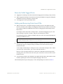
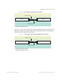
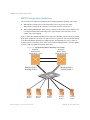
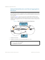
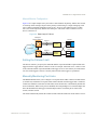
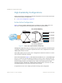
802.1X Authentication Process
The clients and authenticators communicate using Extensible Authentication Protocol (EAP),
which was originally designed to run over PPP, and for which the IEEE 802.1X Standard has
defined an encapsulation method over Ethernet frames, called EAP over LAN (EAPOL).
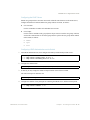
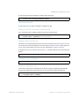
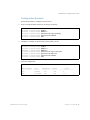
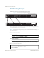
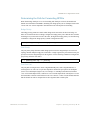
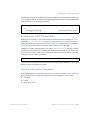
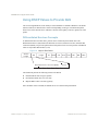
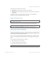
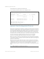
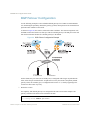
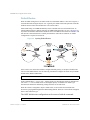
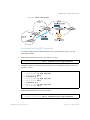
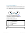
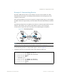
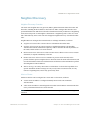
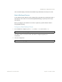
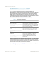
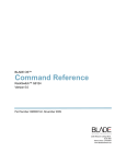
Figure 1 shows a typical message exchange initiated by the client.
42 Chapter 2: Port-based Network Access Control
BMD00136, November 2009
BLADE OS 5.1 Application Guide
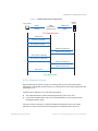
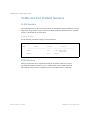
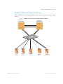
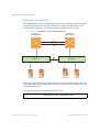
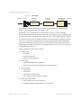
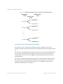
Figure 1 Authenticating a Port Using EAPoL
RADIUS
Server
802.1X Client
G8000
(Authenticator)
(RADIUS Client)
EAPOL
Ethernet
RADIUS-EAP
UDP/IP
Port Unauthorized
EAPOL-Start
EAP-Request (Identity)
EAP-Response (Identity)
Radius-Access-Request
Radius-Access-Challenge
EAP-Request (Credentials)
EAP-Response (Credentials)
Radius-Access-Request
Radius-Access-Accept
EAP-Success
Port Authorized
EAPoL Message Exchange
During authentication, EAPOL messages are exchanged between the client and the G8000
authenticator, while RADIUS-EAP messages are exchanged between the G8000 authenticator and
the RADIUS server.
Authentication is initiated by one of the following methods:
The G8000 authenticator sends an EAP-Request/Identity packet to the client
Client sends an EAPOL-Start frame to the G8000 authenticator, which responds with an
EAP-Request/Identity frame.
The client confirms its identity by sending an EAP-Response/Identity frame to the G8000
authenticator, which forwards the frame encapsulated in a RADIUS packet to the server.
BMD00136, November 2009
Chapter 2: Port-based Network Access Control 43
BLADE OS 5.1 Application Guide
The RADIUS authentication server chooses an EAP-supported authentication algorithm to verify
the client’s identity, and sends an EAP-Request packet to the client via the G8000 authenticator. The
client then replies to the RADIUS server with an EAP-Response containing its credentials.
Upon a successful authentication of the client by the server, the 802.1X-controlled port transitions
from unauthorized to authorized state, and the client is allowed full access to services through the
controlled port. When the client later sends an EAPOL-Logoff message to the G8000 authenticator,
the port transitions from authorized to unauthorized state.
If a client that does not support 802.1X connects to an 802.1X-controlled port, the G8000
authenticator requests the client's identity when it detects a change in the operational state of the
port. The client does not respond to the request, and the port remains in the unauthorized state.
Note – When an 802.1X-enabled client connects to a port that is not 802.1X-controlled, the client
initiates the authentication process by sending an EAPOL-Start frame. When no response is
received, the client retransmits the request for a fixed number of times. If no response is received,
the client assumes the port is in authorized state, and begins sending frames, even if the port is
unauthorized.
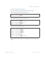
802.1X Port States
The state of the port determines whether the client is granted access to the network, as follows:
Unauthorized
While in this state the port discards all ingress and egress traffic except EAP packets.
Authorized
When the client is successfully authenticated, the port transitions to the authorized state
allowing all traffic to and from the client to flow normally.
Force Unauthorized
You can configure this state that denies all access to the port.
Force Authorized
You can configure this state that allows full access to the port.
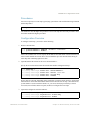
Use the 802.1X global configuration commands (dot1x) to configure 802.1X authentication for all
ports in the switch. Use the 802.1X port commands to configure a single port.
44 Chapter 2: Port-based Network Access Control
BMD00136, November 2009
BLADE OS 5.1 Application Guide
Supported RADIUS Attributes
The G8000 802.1X Authenticator relies on external RADIUS servers for authentication
with EAP. Table 6 lists the RADIUS attributes that are supported as part of
RADIUS-EAP authentication based on the guidelines specified in Annex D of the 802.1X
standard and RFC 3580.
Table 6 Support for RADIUS Attributes
#
Attribute
Attribute Value
A-R
1
User-Name
1
The value of the Type-Data field from the supplicant’s
EAP-Response/Identity message. If the Identity is
unknown (i.e. Type-Data field is zero bytes in length), this
attribute will have the same value as the Calling-Station-Id.
4
NAS-IP-Address
IP address of the authenticator used for Radius
communication.
5
NAS-Port
A-A
A-C
A-R
0-1
0
0
1
0
0
0
Port number of the authenticator port to which the
supplicant is attached.
1
0
0
0
24 State
Server-specific value. This is sent unmodified back to the
server in an Access-Request that is in response to an
Access-Challenge.
0-1
0-1
0-1
0
30 Called-Station-ID
The MAC address of the authenticator encoded as an
ASCII string in canonical format, e.g. 000D5622E3 9F.
1
0
0
0
31 Calling-Station-ID
The MAC address of the supplicant encoded as an ASCII
string in canonical format, e.g. 00034B436206.
1
0
0
0
79 EAP-Message
Encapsulated EAP packets from the supplicant to the
authentication server (Radius) and vice-versa. The
authenticator relays the decoded packet to both devices.
1+
1+
1+
1+
80 Message-Authenticator
Always present whenever an EAP-Message attribute is also 1
included. Used to integrity-protect a packet.
1
1
1
87 NAS-Port-ID
Name assigned to the authenticator port, e.g. Server1_Port3 1
0
0
0
Legend:
RADIUS Packet Types: A-R (Access-Request), A-A (Access-Accept), A-C (Access-Challenge), A-R (Access-Reject)
RADIUS Attribute Support:
0 This attribute MUST NOT be present in a packet.
0+ Zero or more instances of this attribute MAY be present in a packet.
0-1 Zero or one instance of this attribute MAY be present in a packet.
1 Exactly one instance of this attribute MUST be present in a packet.
1+ One or more of these attributes MUST be present.
BMD00136, November 2009
Chapter 2: Port-based Network Access Control 45
BLADE OS 5.1 Application Guide
Configuration Guidelines
When configuring EAPoL, consider the following guidelines:
The 802.1X port-based authentication is currently supported only in point-to-point
configurations, that is, with a single supplicant connected to an 802.1X-enabled switch port.
When 802.1X is enabled, a port has to be in the authorized state before any other Layer 2
feature can be operationally enabled. For example, the STG state of a port is operationally
disabled while the port is in the unauthorized state.
The 802.1X supplicant capability is not supported. Therefore, none of its ports can successfully
connect to an 802.1X-enabled port of another device, such as another switch, that acts as an
authenticator, unless access control on the remote port is disabled or is configured in
forced-authorized mode. For example, if a G8000 is connected to another G8000, and if
802.1X is enabled on both switches, the two connected ports must be configured in
force-authorized mode.
The 802.1X standard has optional provisions for supporting dynamic virtual LAN
assignment via RADIUS tunnelling attributes, for example, Tunnel-Type (=VLAN),
Tunnel-Medium-Type (=802), and Tunnel-Private-Group-ID (=VLAN ID).
These attributes are not supported and might affect 802.1X operations. Other unsupported
attributes include Service-Type, Session-Timeout, and Termination-Action.
RADIUS accounting service for 802.1X-authenticated devices or users is not supported.
Configuration changes performed using SNMP and the standard 802.1X MIB will take effect
immediately.
46 Chapter 2: Port-based Network Access Control
BMD00136, November 2009
CHAPTER 3
VLANs
This chapter describes network design and topology considerations for using Virtual Local Area
Networks (VLANs). VLANs commonly are used to split up groups of network users into
manageable broadcast domains, to create logical segmentation of workgroups, and to enforce
security policies among logical segments. The following topics are discussed in this chapter:
“VLANs and Port VLAN ID Numbers” on page 48
“VLAN Tagging” on page 50
“VLAN Topologies and Design Considerations” on page 54
This section discusses how you can connect users and segments to a host that supports many
logical segments or subnets by using the flexibility of the multiple VLAN system.
“Protocol-Based VLANs” on page 58
“Private VLANs” on page 61
Note – VLANs can be configured from the Command Line Interface (see “VLAN Configuration”
as well as “Port Configuration” in the Command Reference).
Overview
Setting up virtual LANs (VLANs) is a way to segment networks to increase network flexibility
without changing the physical network topology. With network segmentation, each switch port
connects to a segment that is a single broadcast domain. When a switch port is configured to be a
member of a VLAN, it is added to a group of ports (workgroup) that belong to one broadcast
domain.
Ports are grouped into broadcast domains by assigning them to the same VLAN. Frames received in
one VLAN can only be forwarded within that VLAN, and multicast, broadcast, and unknown
unicast frames are flooded only to ports in the same VLAN. The G8000 supports jumbo frames up
to 9,216 bytes.
BMD00136, November 2009
47
BLADE OS 5.1 Application Guide
VLANs and Port VLAN ID Numbers
VLAN Numbers
The G8000 supports up to 1024 VLANs per switch. Even though the maximum number of VLANs
supported at any given time is 1024, each can be identified with any number between 1 and 4094.
VLAN 1 is the default VLAN for all ports.
Viewing VLANs
Use the following command to display VLAN information:
RS G8000 (config)# show vlan
VLAN
---1
Name
-----------------------VLAN 1
Status
-----ena
2
VLAN 2
dis
Ports
------------------------1-48, XGE2-XGE4
po1-po104
empty
PVID Numbers
Each port in the switch has a configurable default VLAN number, known as its PVID.
By default, the PVID for all ports is set to 1, which correlates to the default VLAN ID.
The PVID for each port can be configured to any VLAN number between 1 and 4094.
48 Chapter 3: VLANs
BMD00136, November 2009
BLADE OS 5.1 Application Guide
Viewing and Configuring PVIDs
Use the following CLI commands to view PVIDs:
Port information:
RS G8000# show interface information
Alias Port Tag Edge Lrn Fld PVID
NAME
----- ---- --- ---- --- --- ---- -------------1
1
y
n
e
e
1 1
2
2
y
n
e
e
1 2
3
3
y
n
e
e
1 3
4
4
y
n
e
e
1 4
5
5
y
n
e
e
1 5
6
6
y
n
e
e
1 6
... ...
...
44 44
n
n
e
e
1 44
45 45
n
n
e
e
1 45
46 46
n
n
e
e
1 46
47 47
n
n
e
e
1 47
48 48
n
n
e
e
1 48
XGE1 49
n
n
e
e
1 49
XGE2 50
n
n
e
e
1 50
XGE3 51
n
n
e
e
1 51
XGE4 52
n
n
e
e
1 52
VLAN(s)
-------------------1
1
1
1
1
1
...
1
1
1
1
1
1
1
1
1
* = PVID is tagged.
Port Configuration:
RS G8000 (config)# interface port 7
RS G8000 (config-if)# pvid 7
Each port on the switch can belong to one or more VLANs, and each VLAN can have any number
of switch ports in its membership. Any port that belongs to multiple VLANs, however, must have
VLAN tagging enabled (see “VLAN Tagging” on page 50).
BMD00136, November 2009
Chapter 3: VLANs 49
BLADE OS 5.1 Application Guide
VLAN Tagging
Blade OS software supports IEEE 802.1Q VLAN tagging, providing standards-based VLAN
support for Ethernet systems.
Tagging places the VLAN identifier in the frame header of a packet, allowing each port to belong to
multiple VLANs. When you add a port to multiple VLANs, you also must enable tagging on that
port.
Since tagging fundamentally changes the format of frames transmitted on a tagged port, you must
carefully plan network designs to prevent tagged frames from being transmitted to devices that do
not support 802.1Q VLAN tags, or devices where tagging is not enabled.
Important terms used with the 802.1Q tagging feature are:
VLAN identifier (VID)—the 12-bit portion of the VLAN tag in the frame header that identifies
an explicit VLAN.
Port VLAN identifier (PVID)—a classification mechanism that associates a port with a
specific VLAN. For example, a port with a PVID of 3 (PVID =3) assigns all untagged frames
received on this port to VLAN 3. Any untagged frames received by the switch are classified
with the PVID of the receiving port.
Tagged frame—a frame that carries VLAN tagging information in the header. This VLAN
tagging information is a 32-bit field (VLAN tag) in the frame header that identifies the frame as
belonging to a specific VLAN. Untagged frames are marked (tagged) with this classification as
they leave the switch through a port that is configured as a tagged port.
Untagged frame— a frame that does not carry any VLAN tagging information in the frame
header.
Untagged member—a port that has been configured as an untagged member of a specific
VLAN. When an untagged frame exits the switch through an untagged member port, the frame
header remains unchanged. When a tagged frame exits the switch through an untagged member
port, the tag is stripped and the tagged frame is changed to an untagged frame.
Tagged member—a port that has been configured as a tagged member of a specific VLAN.
When an untagged frame exits the switch through a tagged member port, the frame header is
modified to include the 32-bit tag associated with the PVID. When a tagged frame exits the
switch through a tagged member port, the frame header remains unchanged (original VID
remains).
Note – If a 802.1Q tagged frame is received by a port that has VLAN-tagging disabled and the port
VLAN ID (PVID) is different than the VLAN ID of the packet, then the frame is dropped at the
ingress port.
50 Chapter 3: VLANs
BMD00136, November 2009
BLADE OS 5.1 Application Guide
Figure 2 Default VLAN settings
802.1Q Switch
VLAN 1
Port 1
Port 2
Port 3
Port 4
Port 5
Port 6
Port 7
...
PVID = 1
DA
CRC
SA
Incoming
untagged
packet
Data
Outgoing
untagged packet
(unchanged)
CRC
Data
SA
DA
Key
By default:
All ports are assigned PVID = 1
All ports are untagged members of VLAN 1
BS45010A
Note – The port numbers specified in these illustrations may not directly correspond to the physical
port configuration of your switch model.
When a VLAN is configured, ports are added as members of the VLAN, and the ports are defined as
either tagged or untagged (see Figure 3 through Figure 6).
The default configuration settings for the G8000 has all ports set as untagged members of VLAN 1
with all ports configured as PVID = 1. In the default configuration example shown in Figure 2, all
incoming packets are assigned to VLAN 1 by the default port VLAN identifier (PVID =1).
Figure 3 through Figure 6 illustrate generic examples of VLAN tagging. In Figure 3, untagged
incoming packets are assigned directly to VLAN 2 (PVID = 2). Port 5 is configured as a tagged
member of VLAN 2, and port 7 is configured as an untagged member of VLAN 2.
Note – The port assignments in the following figures are not meant to match the G8000.
BMD00136, November 2009
Chapter 3: VLANs 51
BLADE OS 5.1 Application Guide
Figure 3 Port-based VLAN assignment
Data
SA
Port 4
CRC
DA
Port 2
Port 3
Tagged member
of VLAN 2
Port 5
Port 1
PVID = 2
Untagged packet
802.1Q Switch
Before
Port 6
Port 7
Port 8
Untagged member
of VLAN 2
BS45011A
As shown in Figure 4, the untagged packet is marked (tagged) as it leaves the switch through port 5,
which is configured as a tagged member of VLAN 2. The untagged packet remains unchanged as it
leaves the switch through port 7, which is configured as an untagged member of VLAN 2.
Figure 4 802.1Q tagging (after port-based VLAN assignment)
Port 4
Port 1
Port 2
802.1Q Switch
Port 6
Untagged memeber
of VLAN 2
Port 7
Tagged member
of VLAN 2
Port 3
Port 8
Port 5
PVID = 2
CRC*
Data
Tag
SA
DA
(*Recalculated)
CRC
8100
Priority
CFI
VID = 2
16 bits
3 bits
1 bits
12 bits
Data
After
Outgoing
untagged packet
(unchanged)
SA
DA
Key
Priority
CFI
VID
- User_priority
- Canonical format indicator
- VLAN identifier
BS45012A
In Figure 5, tagged incoming packets are assigned directly to VLAN 2 because of the tag
assignment in the packet. Port 5 is configured as a tagged member of VLAN 2, and port 7 is
configured as an untagged member of VLAN 2.
52 Chapter 3: VLANs
BMD00136, November 2009
BLADE OS 5.1 Application Guide
Figure 5 802.1Q tag assignment
Data
Tag
SA
Port 4
CRC
DA
Port 2
Port 3
Tagged member
of VLAN 2
Port 5
Port 1
PVID = 2
Tagged packet
802.1Q Switch
Before
Port 6
Port 7
Port 8
Untagged member
of VLAN 2
BS45013A
As shown in Figure 6, the tagged packet remains unchanged as it leaves the switch through port 5,
which is configured as a tagged member of VLAN 2. However, the tagged packet is stripped
(untagged) as it leaves the switch through port 7, which is configured as an untagged member of
VLAN 2.
Figure 6 802.1Q tagging (after 802.1Q tag assignment)
Port 4
Port 1
Port 2
802.1Q Switch
Port 6
Untagged member
of VLAN 2
Port 7
CRC*
Tagged member
of VLAN 2
Port 3
Port 5
PVID = 2
CRC
Data
Tag
SA
DA
Port 8
(*Recalculated)
8100
Priority
CFI
VID = 2
16 bits
3 bits
1 bit
12 bits
Data
SA
DA
Outgoing
untagged packet
changed
(tag removed)
After
Key
Priority
CFI
VID
- User_priority
- Canonical format indicator
- VLAN identifier
BS45014A
BMD00136, November 2009
Chapter 3: VLANs 53
BLADE OS 5.1 Application Guide
VLAN Topologies and Design Considerations
By default, the G8000 software is configured so that tagging is disabled on all ports.
By default, the G8000 software is configured so that all ports are members of VLAN 1.
If you configure Spanning Tree, note that Spanning Tree Groups 2-128 may contain only one
VLAN.
VLAN Configuration Rules
VLANs operate according to specific configuration rules. When creating VLANs, consider the
following rules that determine how the configured VLAN reacts in any network topology:
All ports involved in trunking and port mirroring must have the same VLAN configuration. If
a port is on a trunk with a mirroring port, the VLAN configuration cannot be changed. For
more information trunk groups, see “Port Trunking Example” on page 68.
All ports that are involved in port mirroring must have memberships in the same VLANs. If a
port is configured for port mirroring, the port’s VLAN membership cannot be changed. For
more information on configuring port mirroring, see “Monitoring Ports” on page 207.
54 Chapter 3: VLANs
BMD00136, November 2009
BLADE OS 5.1 Application Guide
Multiple VLANs with Tagging Adapters
Figure 7 illustrates a network topology described in Table 7 and the configuration example on page
page 57.
Figure 7 Multiple VLANs with VLAN-Tagged Gigabit Adapters
Enterprise
Routing Switch
Server 1
VLAN 1
BMD00136, November 2009
Server 2
VLAN 1
Enterprise
Routing Switch
Server 3
VLAN 2
Server 4
VLAN 3
Server 5
VLAN 1, 2
Chapter 3: VLANs 55
BLADE OS 5.1 Application Guide
The features of this VLAN are described below:
Table 7 Multiple VLANs Example
Component
Description
G8000 switch
This switch is configured with three VLANs that represent three different IP
subnets. Five ports are connected downstream to servers.
Two ports are connected upstream to routing switches.
Uplink ports are members of all three VLANs, with VLAN tagging enabled.
Server 1
This server is a member of VLAN 1 and has presence in only one IP subnet.
The associated switch port is only a member of VLAN 1, so tagging is
disabled.
Server 2
This server is a member of VLAN 1 and has presence in only one IP subnet.
The associated switch port is only a member of VLAN 1, so tagging is
disabled.
Server 3
This server belongs to VLAN 2, and it is logically in the same IP subnet as
Server 5.
The associated switch port has tagging disabled.
Server 4
A member of VLAN 3, this server can communicate only with other servers
via a router.
The associated switch port has tagging disabled.
Server 5
A member of VLAN 1 and VLAN 2, this server can communicate only with
Server 1, Server 2, and Server 3.
The associated switch port has tagging enabled.
Enterprise
Routing switches
These switches must have all three VLANs (VLAN 1, 2, 3) configured. They
can communicate with Server 1, Server 2, and Server 5 via VLAN 1.
They can communicate with Server 3 and Server 5 via VLAN 2.
They can communicate with Server 4 via VLAN 3.
Tagging on switch ports is enabled.
Note – VLAN tagging is required only on ports that are connected to other switches or on ports that
connect to tag-capable end-stations, such as servers with VLAN-tagging adapters.
56 Chapter 3: VLANs
BMD00136, November 2009
BLADE OS 5.1 Application Guide
VLAN Configuration Example
Use the following procedure to configure the example network shown in Figure 7.
1. Enable VLAN tagging on ports that support multiple VLANs.
RS G8000 (config)# interface port 5
RS G8000 (config-if)# tagging
RS G8000 (config-if)# exit
2. Enable tagging on uplink ports that support multiple VLANs.
RS
RS
RS
RS
RS
RS
G8000
G8000
G8000
G8000
G8000
G8000
(config)# interface port 47
(config-if)# tagging
(config-if)# exit
(config)# interface port 48
(config-if)# tagging
(config-if)# exit
3. Configure the VLANs and their member ports.
RS
RS
RS
RS
RS
RS
RS
RS
RS
RS
RS
G8000
G8000
G8000
G8000
G8000
G8000
G8000
G8000
G8000
G8000
G8000
(config)# vlan
(config-vlan)#
(config-vlan)#
(config-vlan)#
(config-vlan)#
(config-vlan)#
(config-vlan)#
(config)# vlan
(config-vlan)#
(config-vlan)#
(config-vlan)#
2
enable
member
member
member
member
exit
3
enable
member
exit
3
5
47
48
4,47,48
By default, all ports are members of VLAN 1, so configure only those ports that belong to other
VLANs.
BMD00136, November 2009
Chapter 3: VLANs 57
BLADE OS 5.1 Application Guide
Protocol-Based VLANs
Protocol-based VLANs (PVLANs) allow you to segment network traffic according to the network
protocols in use. Traffic for supported network protocols can be confined to a particular port-based
VLAN. You can give different priority levels to traffic generated by different network protocols.
With PVLAN, the switch classifies incoming packets by Ethernet protocol of the packets, not by the
configuration of the ingress port. When an untagged or priority-tagged frame arrives at an ingress
port, the protocol information carried in the frame is used to determine a VLAN to which the frame
belongs. If a frame’s protocol is not recognized as a pre-defined PVLAN type, the ingress port’s
PVID is assigned to the frame. When a tagged frame arrives, the VLAN ID in the frame’s tag is
used.
Each VLAN can contain up to eight different PVLANs. You can configure separate PVLANs on
different VLANs, with each PVLAN segmenting traffic for the same protocol type. For example,
you can configure PVLAN 1 on VLAN 2 to segment IPv4 traffic, and PVLAN 8 on VLAN 100 to
segment IPv4 traffic.
To define a PVLAN on a VLAN, configure a PVLAN number (1-8) and specify the frame type and
the Ethernet type of the PVLAN protocol. You must assign at least one port to the PVLAN before it
can function. Define the PVLAN frame type and Ethernet type as follows:
Frame type—consists of one of the following values:
Ether2 (Ethernet II)
SNAP (Subnetwork Access Protocol)
LLC (Logical Link Control)
Ethernet type—consists of a 4-digit (16 bit) hex value that defines the Ethernet type. You can
use common Ethernet protocol values, or define your own values. Following are examples of
common Ethernet protocol values:
IPv4 = 0800
IPv6 = 86dd
ARP = 0806
58 Chapter 3: VLANs
BMD00136, November 2009
BLADE OS 5.1 Application Guide
Port-Based vs. Protocol-Based VLANs
Each VLAN supports both port-based and protocol-based association, as follows:
The default VLAN configuration is port-based. All data ports are members of VLAN 1, with no
PVLAN association.
When you add ports to a PVLAN, the ports become members of both the port-based VLAN and
the PVLAN. For example, if you add port 1 to PVLAN 1 on VLAN 2, the port also becomes a
member of VLAN 2.
When you delete a PVLAN, it’s member ports remain members of the port-based VLAN. For
example, if you delete PVLAN 1 from VLAN 2, port 1 remains a member of VLAN 2.
When you delete a port from a VLAN, the port is deleted from all corresponding PVLANs.
PVLAN Priority Levels
You can assign each PVLAN a priority value of 0-7, used for Quality of Service (QoS). PVLAN
priority takes precedence over a port’s configured priority level. If no priority level is configured for
the PVLAN (priority = 0), each port’s priority is used (if configured).
All member ports of a PVLAN have the same PVLAN priority level.
PVLAN Tagging
When PVLAN tagging is enabled, the switch tags frames that match the PVLAN protocol. For
more information about tagging, see “VLAN Tagging” on page 50.
Untagged ports must have PVLAN tagging disabled. Tagged ports can have PVLAN tagging either
enabled or disabled.
PVLAN tagging has higher precedence than port-based tagging. If a port is tag enabled, and the port
is a member of a PVLAN, the PVLAN tags egress frames that match the PVLAN protocol.
Use the tag list command (protocol-vlan <x> tag-pvlan) to define the complete list of
tag-enabled ports in the PVLAN. Note that all ports not included in the PVLAN tag list will have
PVLAN tagging disabled.
BMD00136, November 2009
Chapter 3: VLANs 59
BLADE OS 5.1 Application Guide
PVLAN Configuration Guidelines
Consider the following guidelines when you configure protocol-based VLANs:
Each port can support up to 16 VLAN protocols.
The G8000 can support up to 16 protocols simultaneously.
Each PVLAN must have at least one port assigned before it can be activated.
The same port within a port-based VLAN can belong to multiple PVLANs.
An untagged port can be a member of multiple PVLANs.
A port cannot be a member of different VLANs with the same protocol association.
Configuring PVLAN
Follow this procedure to configure a Protocol-based VLAN (PVLAN).
1. Configure VLAN tagging for ports.
RS G8000 (config)# interface port 1, 2
RS G8000 (config-if)# tagging
2. Create a VLAN and define the protocol type(s) supported by the VLAN.
RS G8000 (config)# vlan 2
RS G8000 (config-vlan)# enable
Current status: disabled
New status:
enabled
RS G8000 (config-vlan)# protocol-vlan 1 frame-type ether2 0800
3. Configure the priority value for the protocol.
RS G8000 (config-vlan)# protocol-vlan 1 priority 2
4. Add member ports for this PVLAN.
RS G8000 (config-vlan)# member 1, 2
RS G8000 (config-vlan)# exit
Note – If VLAN tagging is turned on and the port being added to the VLAN has a different default
VLAN (PVID), you will be asked to confirm changing the PVID to the current VLAN, as shown in
the example.
60 Chapter 3: VLANs
BMD00136, November 2009
BLADE OS 5.1 Application Guide
5. Enable the PVLAN.
RS G8000 (config-vlan)# protocol-vlan 1 enable
6. Verify PVLAN operation.
RS G8000 (config)# show protocol-vlan
PVLAN
----1
Protocol
-------2
FrameType EtherType
-------------------ether2
0800
PVLAN
----1
PVLAN-Tagged Ports
--------------------------1, 2
Priority
-------2
Status
-----ena
Ports
----------1, 2
Private VLANs
Private VLANs provide Layer 2 isolation between the ports within the same broadcast domain.
Private VLANs can control traffic within a VLAN domain, and provide port-based security for host
servers.
Use Private VLANs to partition a VLAN domain into sub-domains. Each sub-domain is comprised
of one primary VLAN and one or more secondary VLANs, as follows:
Primary VLAN—carries unidirectional traffic downstream from promiscuous ports. Each
Private VLAN configuration has only one primary VLAN. All ports in the Private VLAN are
members of the Primary VLAN.
Secondary VLAN—Secondary VLANs are internal to a private VLAN domain, and are
defined as follows:
Isolated VLAN—carries unidirectional traffic upstream from the host servers toward ports
in the primary VLAN and the gateway. Each Private VLAN configuration can contain only
one isolated VLAN.
Community VLAN—carries upstream traffic from ports in the community VLAN to other
ports in the same community, and to ports in the primary VLAN and the gateway. Each
Private VLAN can contain multiple community VLANs.
After you define the primary VLAN and one or more secondary VLANs, you map the secondary
VLAN(s) to the primary VLAN.
BMD00136, November 2009
Chapter 3: VLANs 61
BLADE OS 5.1 Application Guide
Private VLAN Ports
Private VLAN ports are defined as follows:
Promiscuous—A promiscuous port is a port that belongs to the primary VLAN. The
promiscuous port can communicate with all the interfaces, including ports in the secondary
VLANs (Isolated VLAN and Community VLANs). Each promiscuous port can belong to only
one Private VLAN.
Isolated—An isolated port is a host port that belongs to an isolated VLAN. Each isolated port
has complete layer 2 separation from other ports within the same private VLAN (including
other isolated ports), except for the promiscuous ports.
Traffic sent to an isolated port is blocked by the Private VLAN, except the traffic from
promiscuous ports.
Traffic received from an isolated port is forwarded only to promiscuous ports.
Community—A community port is a host port that belongs to a community VLAN.
Community ports can communicate with other ports in the same community VLAN, and with
promiscuous ports. These interfaces are isolated at layer 2 from all other interfaces in other
communities and from isolated ports within the Private VLAN.
Configuration Guidelines
The following guidelines apply when configuring Private VLANs:
The default VLAN 1 cannot be a Private VLAN.
IGMP Snooping must be disabled on isolated VLANs.
Each secondary port’s (isolated port and community ports) PVID must match its corresponding
secondary VLAN ID.
Ports within a secondary VLAN cannot be members of other VLANs.
All VLANs that comprise the Private VLAN must belong to the same Spanning Tree Group.
62 Chapter 3: VLANs
BMD00136, November 2009
BLADE OS 5.1 Application Guide
Configuration Example
Follow this procedure to configure a Private VLAN.
1. Select a VLAN and define the Private VLAN type as primary.
RS
RS
RS
RS
RS
RS
G8000
G8000
G8000
G8000
G8000
G8000
(config)# vlan
(config-vlan)#
(config-vlan)#
(config-vlan)#
(config-vlan)#
(config-vlan)#
100
enable
member 2
private-vlan type primary
private-vlan enable
exit
2. Configure a secondary VLAN and map it to the primary VLAN.
RS
RS
RS
RS
RS
RS
RS
RS
G8000
G8000
G8000
G8000
G8000
G8000
G8000
G8000
(config)# vlan
(config-vlan)#
(config-vlan)#
(config-vlan)#
(config-vlan)#
(config-vlan)#
(config-vlan)#
(config-vlan)#
110
enable
member 3
member 4
private-vlan type isolated
private-vlan map 100
private-vlan enable
exit
3. Verify the configuration.
RS G8000 (config)# show private-vlan
Private-VLAN
-----------100
110
BMD00136, November 2009
Type
Mapped-To
Status
--------- ---------- ---------primary
110
ena
isolated
100
ena
Ports
----------------2
3-4
Chapter 3: VLANs 63
BLADE OS 5.1 Application Guide
64 Chapter 3: VLANs
BMD00136, November 2009
CHAPTER 4
Ports and Trunking
Trunk groups can provide super-bandwidth, multi-link connections between switches or other
trunk-capable devices. A trunk group is a group of ports that act together, combining their
bandwidth to create a single, larger virtual link. This chapter provides configuration background and
examples for trunking multiple ports together:
““Overview” on page 65”
“Port Trunking Example” on page 68
“Configurable Trunk Hash Algorithm” on page 69
“Link Aggregation Control Protocol” on page 70
Overview
When using port trunk groups between two switches, as shown in Figure 8, you can create
a virtual link between the switches, operating up to 40 Gb per second, depending on how
many physical ports are combined. Each G8000 supports up to 52 static trunk groups (portchannels)
and up to 52 LACP trunk groups, consisting of 1-8 ports in each group.
Trunk groups are also useful for connecting a G8000 to third-party devices that support link
aggregation, such as Cisco routers and switches with EtherChannel technology (not ISL trunking
technology) and Sun's Quad Fast Ethernet Adapter. Trunk Group technology is compatible with
these devices when they are configured manually.
Statistical Load Distribution
Network traffic is distributed statistically between the ports in a trunk group. The switch can use a
combination of Layer 2 MAC and Layer 3 IP address information, present in each transmitted
frame, to determine load distribution.
BMD00136, November 2009
65
BLADE OS 5.1 Application Guide
Each packet’s particular MAC or IP address information results in selecting one line in the trunk
group for data transmission. The more data streams feeding the trunk lines, the more evenly traffic
distribution becomes.
Built-In Fault Tolerance
Since each trunk group is comprised of multiple physical links, the trunk group is inherently fault
tolerant. As long as one connection between the switches is available, the trunk remains active.
Statistical load balancing is maintained whenever a port in a trunk group is lost or returned to
service.
Before You Configure Static Trunks
When you create and enable a static trunk, the trunk members (switch ports) take on certain settings
necessary for correct operation of the trunking feature.
Before you configure your trunk, you must consider these settings, along with specific
configuration rules, as follows:
1.
Read the configuration rules provided in the section, “Static Trunk Group Configuration Rules” on
page 67.
2.
Determine which switch ports (up to eight) are to become trunk members (the specific ports making
up the trunk).
Ensure that the chosen switch ports are set to enabled. Trunk member ports must have the same
VLAN and Spanning Tree configuration.
3.
Consider how the existing Spanning Tree will react to the new trunk configuration. See Chapter 5,
“Spanning Tree Group” for Spanning Tree Group configuration guidelines.
4.
Consider how existing VLANs will be affected by the addition of a trunk.
66 Chapter 4: Ports and Trunking
BMD00136, November 2009
BLADE OS 5.1 Application Guide
Static Trunk Group Configuration Rules
The trunking (portchannel) feature operates according to specific configuration rules. When
creating trunks, consider the following rules that determine how a trunk group reacts in any network
topology:
All trunks must originate from one device, and lead to one destination device.
Any physical switch port can belong to only one trunk group.
Trunking from third-party devices must comply with Cisco® EtherChannel® technology.
All trunk member ports must be assigned to the same VLAN configuration before the trunk can
be enabled.
When an active port is configured in a trunk, the port becomes a trunk member when you
enable the trunk. The Spanning Tree parameters for the port then change to reflect the new
trunk settings.
All trunk members must be in the same Spanning Tree Group (STG) and can belong to only
one Spanning Tree Group (STG). However if all ports are tagged, then all trunk ports can
belong to multiple STGs.
If you change the Spanning Tree participation of any trunk member to enabled or
disabled, the Spanning Tree participation of all trunk members changes similarly.
When a trunk is enabled, the trunk’s Spanning Tree participation setting takes precedence over
that of any trunk member.
You cannot configure a trunk member as a monitor port in a port-mirroring configuration.
Trunks cannot be monitored by a monitor port; however, trunk members can be monitored.
All ports in static trunks must be have the same link configuration (speed, duplex, flow
control).
BMD00136, November 2009
Chapter 4: Ports and Trunking 67
BLADE OS 5.1 Application Guide
Port Trunking Example
In the example below, three ports are trunked between two switches.
Figure 8 Port Trunk Group Configuration Example
Trunk 3: Ports 2, 23, and 30
2
30
23
Trunk 1: Ports 1, 7, and 32
1
7
32
Prior to configuring each switch in the above example, you must connect to the appropriate switch’s
Command Line Interface (CLI) as the administrator.
Note – For details about accessing and using any of the commands described in this example, see
the Command Reference.
1. Follow these steps on the G8000:
(a) Define a trunk group.
RS G8000 (config)# portchannel 3 member 2,23,30
RS G8000 (config)# portchannel 3 enable
(b) Verify the configuration.
# show portchannel information
Examine the resulting information. If any settings are incorrect, make appropriate changes.
2. Repeat the process on the other switch.
RS G8000 (config)# portchannel 1 member 1,7,32
RS G8000 (config)# portchannel 1 enable
# show portchannel
68 Chapter 4: Ports and Trunking
BMD00136, November 2009
BLADE OS 5.1 Application Guide
3. Connect the switch ports that will be members in the trunk group.
Trunk group 3 (on the G8000) is now connected to trunk group 1 (on the other switch).
Note – In this example, two G8000 switches are used. If a third-party device supporting link
aggregation is used (such as Cisco routers and switches with EtherChannel technology or Sun's
Quad Fast Ethernet Adapter), trunk groups on the third-party device should be configured manually.
Connection problems could arise when using automatic trunk group negotiation on the third-party
device.
4. Examine the trunking information on each switch.
# show portchannel information
PortChannel 3: Enabled
port state:
2: STG 1 forwarding
23: STG 1 forwarding
30: STG 1 forwarding
Information about each port in each configured trunk group is displayed. Make sure that trunk
groups consist of the expected ports and that each port is in the expected state.
The following restrictions apply:
Any physical switch port can belong to only one trunk group.
Up to eight ports can belong to the same trunk group.
All ports in static trunks must be have the same link configuration (speed, duplex, flow
control).
Trunking from third-party devices must comply with Cisco® EtherChannel® technology.
Configurable Trunk Hash Algorithm
This feature allows you to configure parameters for the trunk hash algorithm, instead of using the
default values.
Use the IP Trunk Hash commands to configure new default behavior for Layer 2 traffic and Layer 3
traffic. The trunk hash settings affect both static trunks and LACP trunks.
You can select a minimum of one or a maximum of two parameters to create one of the
following configurations:
Source MAC (SMAC):
RS G8000 (config)# portchannel hash source-mac-address
BMD00136, November 2009
Chapter 4: Ports and Trunking 69
BLADE OS 5.1 Application Guide
Destination MAC (DMAC):
RS G8000 (config)# portchannel hash destination-mac-address
Source MAC (SMAC) + Destination MAC (DMAC):
RS G8000 (config)# portchannel hash source-destination-mac
Source IP (SIP):
RS G8000 (config)# portchannel hash source-ip-address
Destination IP (DIP):
RS G8000 (config)# portchannel hash destination-ip-address
Source IP (SIP) + Destination IP (DIP):
RS G8000 (config)# portchannel hash source-destination-ip
Link Aggregation Control Protocol
Link Aggregation Control Protocol (LACP) is an IEEE 802.3ad standard for grouping several
physical ports into one logical port (known as a dynamic trunk group or Link Aggregation group)
with any device that supports the standard. Please refer to IEEE 802.3ad-2002 for a full description
of the standard.
The 802.3ad standard allows standard Ethernet links to form a single Layer 2 link using the Link
Aggregation Control Protocol (LACP). Link aggregation is a method of grouping physical link
segments of the same media type and speed in full duplex, and treating them as if they were part of
a single, logical link segment. If a link in a LACP trunk group fails, traffic is reassigned
dynamically to the remaining link(s) of the dynamic trunk group.
Note – LACP implementation in the Blade OS does not support the Churn machine, an option used
to detect if the port is operable within a bounded time period between the actor
and the partner. Only the Marker Responder is implemented, and there is no marker protocol
generator.
70 Chapter 4: Ports and Trunking
BMD00136, November 2009
BLADE OS 5.1 Application Guide
A port’s Link Aggregation Identifier (LAG ID) determines how the port can be aggregated. The
Link Aggregation ID (LAG ID) is constructed mainly from the system ID and the port’s admin key,
as follows:
System ID is an integer value based on the switch’s MAC address and the system priority assigned
in the CLI.
Admin key
A port’s Admin key is an integer value (1-65535) that you can configure in the CLI. Each switch
port that participates in the same LACP trunk group must have the same admin key value. The
Admin key is local significant, which means the partner switch does not need to use the same
Admin key value.
For example, consider two switches, an Actor (the G8000) and a Partner (another switch), as shown
in Table 8.
Table 8 Actor vs. Partner LACP configuration
Actor Switch
Partner Switch 1
Port 7 (admin key = 100)
Port 1 (admin key = 50)
Port 8 (admin key = 100)
Port 2 (admin key = 50)
In the configuration shown in Table 8, Actor switch port 7 and port 8 aggregate to form an LACP
trunk group with Partner switch port 1 and port 2.
LACP automatically determines which member links can be aggregated and then aggregates them.
It provides for the controlled addition and removal of physical links for the link aggregation.
Each port on the switch can have one of the following LACP modes.
off (default)
The user can configure this port in to a regular static trunk group.
active
The port is capable of forming an LACP trunk. This port sends LACPDU packets to partner
system ports.
passive
The port is capable of forming an LACP trunk. This port only responds to the LACPDU
packets sent from an LACP active port.
Each active LACP port transmits LACP data units (LACPDUs), while each passive LACP
port listens for LACPDUs. During LACP negotiation, the admin key is exchanged. The LACP
trunk group is enabled as long as the information matches at both ends of the link. If the admin key
value changes for a port at either end of the link, that port’s association with the LACP trunk group
is lost.
BMD00136, November 2009
Chapter 4: Ports and Trunking 71
BLADE OS 5.1 Application Guide
When the system is initialized, all ports by default are in LACP off mode and are assigned unique
admin keys. To make a group of ports aggregatable, you assign them all the same admin key. You
must set the port’s LACP mode to active to activate LACP negotiation. You can set other port’s
LACP mode to passive, to reduce the amount of LACPDU traffic at the initial trunk-forming stage.
Use the following command to check whether the ports are trunked:
RS G8000 # show lacp information
Note – If you configure LACP on ports with 802.1X network access control, make sure the ports
on both sides of the connection are properly configured for both LACP and 802.1X.
LACP Configuration Guidelines
Consider the following guidelines when you configure LACP trunks:
The range of potential LACP trunk IDs is 53-104.
When an LACP trunk forms, the trunk ID is determined by the lowest port number in the trunk.
For example, if the lowest port number is 1, then the LACP trunk ID is 53.
Each port that is configured to participate in LACP must be set to full duplex.
Configuring LACP
Use the following procedure to configure LACP on ports 2-6 to participate in link aggregation.
1. Configure port parameters. All ports that participate in the LACP trunk group must have the same
settings, including VLAN membership.
2.
Select a range of ports and define the admin key. Only ports with the same admin key can form a
LACP trunk group.
RS G8000 (config)# interface port 2-6
RS G8000 (config-if)# lacp key 100
3. Set the LACP mode.
RS G8000 (config-if)# lacp mode active
RS G8000 (config-if)# exit
72 Chapter 4: Ports and Trunking
BMD00136, November 2009
CHAPTER 5
Spanning Tree Group
When multiple paths exist on a network, Spanning Tree Group (STG) configures the network so
that a switch uses only the most efficient path. The following topics are discussed in this chapter:
“STG Overview” on page 73
“Bridge Protocol Data Units (BPDUs)” on page 74
“Multiple Spanning Trees” on page 78
“Multiple Spanning Tree Group Protocol” on page 81
“Port Fast Forwarding” on page 84
“Fast Uplink Convergence” on page 84
“Hot Links” on page 85
STG Overview
Spanning Tree Group (STG) detects and eliminates logical loops in a bridged or switched network.
When multiple paths exist, Spanning Tree configures the network so that a switch uses only the
most efficient path. If that path fails, Spanning Tree automatically sets up another active path on the
network to sustain network operations.
The RackSwitch G8000 (G8000) supports IEEE 802.1D Spanning Tree Protocol. It is compatible
with PVST+ by configuring each STP Group in different STP instances.
Note – The G8000 also supports IEEE 802.1w Rapid Spanning Tree Protocol, and IEEE 802.1s
Multiple Spanning Tree Protocol. For more information, see Chapter 6, “Rapid Spanning Tree
Protocol/Multiple Spanning Tree Protocol.”
BMD00136, November 2009
73
BLADE OS 5.1 Application Guide
The relationship between port, trunk groups, VLANs, and Spanning Trees is shown in Table 9.
Table 9 Ports, Trunk Groups, and VLANs
Switch Element
Belongs To
Port
Trunk group
or
One or more VLANs
Trunk group
One or more VLANs
VLAN (non-default)
One Spanning Tree Group
Note – Due to Spanning Tree’s sequence of listening, learning, and forwarding or blocking,
lengthy delays may occur. You can use Port Fast Forwarding to permit a port that participates in
Spanning Tree to bypass the Listening and Learning states and enter directly into the Forwarding
state. While in the Forwarding state, the port listens to the BPDUs to learn if there is a loop and, if
dictated by normal STG behavior (following priorities, and so on), the port transitions into the
Blocking state. This feature permits the G8000 to interoperate well within Rapid Spanning Tree
networks.
Bridge Protocol Data Units (BPDUs)
BDPU Overview
To create a Spanning Tree, the switch generates a configuration Bridge Protocol Data Unit (BPDU),
which it then forwards out of its ports. All switches in the Layer 2 network participating in the
Spanning Tree gather information about other switches in the network through an exchange of
BPDUs.
A BPDU is a 64-byte packet that is sent out at a configurable interval, which is typically set for two
seconds. The BPDU is used to establish a path, much like a “hello” packet in IP routing. BPDUs
contain information about the transmitting bridge and its ports, including bridge and MAC
addresses, bridge priority, port priority, and path cost. If the ports are tagged, each port sends out a
special BPDU containing the tagged information.
The generic action of a switch on receiving a BPDU is to compare the received BPDU to its own
BPDU that it will transmit. If the received BPDU is better than its own BPDU, it will replace its
BPDU with the received BPDU. Then, the switch adds its own bridge ID number and increments
the path cost of the BPDU. The switch uses this information to block any necessary ports.
74 Chapter 5: Spanning Tree Group
BMD00136, November 2009
BLADE OS 5.1 Application Guide
Determining the Path for Forwarding BPDUs
When determining which port to use for forwarding and which port to block, the RackSwitch
G8000 uses information in the BPDU, including each bridge priority ID. A technique based on the
“lowest root cost” is then computed to determine the most efficient path for forwarding.
Bridge Priority
The bridge priority parameter controls which bridge on the network is the STG root bridge. To
make one switch become the root bridge, configure the bridge priority lower than all other switches
and bridges on your network. The lower the value, the higher the bridge priority. Use the following
command to configure the bridge priority (Global Configuration mode):
>> # spanning-tree stp <x> bridge priority
Port Priority
The port priority helps determine which bridge port becomes the designated port. In a network
topology that has multiple bridge ports connected to a single segment, the port with the lowest port
priority becomes the designated port for the segment. Use the following command to configure the
port priority (Interface Port mode):
>> # spanning-tree stp <x> priority
Port Path Cost
The port path cost assigns lower values to high-bandwidth ports, such as Gigabit Ethernet, to
encourage their use. The cost of a port also depends on whether the port operates at full-duplex
(lower cost) or half-duplex (higher cost). For example, if a 100-Mbps (Fast Ethernet) link has a
“cost” of 10 in half-duplex mode, it will have a cost of 5 in full-duplex mode. The objective is to use
the fastest links so that the route with the lowest cost is chosen. A value of 0 (the default) indicates
that the default cost will be computed for an auto-negotiated link or trunk speed.
BMD00136, November 2009
Chapter 5: Spanning Tree Group 75
BLADE OS 5.1 Application Guide
Spanning Tree Group Guidelines
This section provides important information on configuring Spanning Tree Groups (STGs):
Adding a VLAN to a Spanning Tree Group
If no VLANs exist beyond the default VLAN 1 see “Creating a VLAN” on page 76 for
information on adding ports to VLANs.
Add the VLAN to the STG using the following command:
>> # spanning-tree stp <STG number> vlan <VLAN number>
Note – To ensure proper operation with switches that use Cisco Per VLAN Spanning
Tree (PVST+), you must either create a separate STG for each VLAN, or manually add all
associated VLANs into a single STG.
Creating a VLAN
When you create a VLAN, that VLAN automatically belongs to STG 1, the default STG. If you
want the VLAN in another STG, you must move the VLAN by assigning it to another STG.
Move a newly created VLAN to an existing STG by following this order:
Create the VLAN
Add the VLAN to an existing STG
VLANs must be contained within a single STG; a VLAN cannot span multiple STGs. By
confining VLANs within a single STG, you avoid problems with spanning tree blocking ports
and causing a loss of connectivity within the VLAN. When a VLAN spans multiple switches, it
is recommended that the VLAN remain within the same Spanning Tree Group (have the same
STG ID) across all the switches.
If ports are tagged, all trunked ports can belong to multiple STGs.
A port that is not a member of any VLAN cannot be added to any STG. The port must be added
to a VLAN, and that VLAN added to the desired STG.
76 Chapter 5: Spanning Tree Group
BMD00136, November 2009
BLADE OS 5.1 Application Guide
Rules for VLAN Tagged Ports
Tagged ports can belong to more than one STG, but untagged ports can belong to only one STG.
When a tagged port belongs to more than one STG, the egress BPDUs are tagged to distinguish
the BPDUs of one STG from those of another STG.
An untagged port cannot span multiple STGs.
Adding and Removing Ports from STGs
When you add a port to a VLAN that belongs to an STG, the port is also added to the STG.
However, if the port you are adding is an untagged port and is already a member of an STG, that
port will not be added to an additional STG because an untagged port cannot belong to more
that one STG.
For example, assume that VLAN 1 belongs to STG 1. You add an untagged port, port 1, that
does not belong to any STG to VLAN 1, and port 1 will become part of STG 1.
If you add untagged port 5 (which is a member to STG 2) to STG 1, the switch will prompt you
to change the PVID from 2 to 1:
"Port 5 is an UNTAGGED port and its current PVID is 2.
Confirm changing PVID from 2 to 1 [y/n]:" y
When you remove a port from VLAN that belongs to an STG, that port will also be removed
from the STG. However, if that port belongs to another VLAN in the same STG, the port
remains in the STG.
As an example, assume that port 1 belongs to VLAN 1, and VLAN 1 belongs to STG 1. When
you remove port 1 from VLAN 1, port 1 is also removed from STG 1.
However, if port 1 belongs to both VLAN 1 and VLAN 2 and both VLANs belong to STG 1,
removing port 1 from VLAN 1 does not remove port 1 from STG 1 because VLAN 2 is still a
member of STG 1.
An STG cannot be deleted, only disabled. If you disable the STG while it still contains VLAN
members, Spanning Tree will be off on all ports belonging to that VLAN.
The relationship between port, trunk groups, VLANs, and Spanning Trees is shown in Table 9.
BMD00136, November 2009
Chapter 5: Spanning Tree Group 77
BLADE OS 5.1 Application Guide
Multiple Spanning Trees
Each RackSwitch G8000 supports a maximum of 128 Spanning Tree Groups (STGs). Multiple
STGs provide multiple data paths, which can be used for load-balancing and redundancy.
You enable load balancing between two G8000s using multiple STGs by configuring each path with
a different VLAN and then assigning each VLAN to a separate STG. Each STG is independent.
Each STG sends its own Bridge Protocol Data Units (BPDUs), and each STG must be
independently configured.
The STG, or bridge group, forms a loop-free topology that includes one or more virtual LANs
(VLANs). The switch supports 128 STGs running simultaneously. The default STG 1 may contain
an unlimited number of VLANs. All other STGs 2-128 may contain only one VLAN each.
Default Spanning Tree Configuration
In the default configuration, a single STG with the ID of 1 includes all ports on the switch. It is
called the default STG. Although ports can be added to or deleted from the default STG, the default
STG (STG 1) itself cannot be deleted from the system.
All other STGs are empty and VLANs must be added by the user. However, you cannot assign ports
directly to an STG. Instead, add ports to a VLAN first and then add the VLAN to the STG.
Each STG is enabled by default, and assigned an ID number from 2 to 128.
Why Do We Need Multiple Spanning Trees?
The following examples describe why we need multiple spanning trees.
In Figure 9, VLAN 1 and VLAN 2 pass traffic between switch 1 and switch 2. If you have a single
Spanning Tree Group, the switches see an apparent physical loop, and one VLAN may become
blocked, affecting connectivity, even though no logical loop exists. VLAN 2 traffic is blocked
unnecessarily.
78 Chapter 5: Spanning Tree Group
BMD00136, November 2009
BLADE OS 5.1 Application Guide
Figure 9 Two VLANs on one Spanning Tree Group
VLAN 1, STG 1
Switch 1
X
Switch 2
VLAN 2, STG 1
VLAN 2 traffic blocked by STG 1
In Figure 10, VLAN 1 and VLAN 2 belong to different Spanning Tree Groups. The two instances of
Spanning Tree separate the topology without forming a loop. Both VLANs can forward packets
between the switches without losing connectivity.
Figure 10 Two VLANs, each on a different Spanning Tree Group
VLAN 1, STG 1
Switch 2
Switch 1
VLAN 2, STG 2
VLAN 1 passes traffic on STG 1
VLAN 2 passes traffic on STG 2
BMD00136, November 2009
Chapter 5: Spanning Tree Group 79
BLADE OS 5.1 Application Guide
Spanning Tree with ISLs
This configuration shows how to configure Spanning Tree Protocol with Inter-Switch Links (ISLs).
In normal operation, the ISL is blocked by Spanning Tree. If there is an uplink failure on one
switch, the ISL becomes active, and traffic passes through the ISL to the active uplink.
Figure 11 Spanning Tree with Inter-Switch Links
Enterprise
Routing Switch
Enterprise
Routing Switch
Switch 1
Server 1
Server 2
x
Switch 2
Server 3
Server 4
In the example illustrated in Figure 11, assume that port 50 on each switch is used for the ISL. To
ensure that the ISL is blocked during normal operation, set the port path cost to a higher value than
other paths in the network.
Configure the port path cost on the ISL port for both switches.
RS G8000 (config)# interface port 50
RS G8000 (config-if)# spanning-tree stp 1 path-cost 60000
80 Chapter 5: Spanning Tree Group
BMD00136, November 2009
BLADE OS 5.1 Application Guide
Multiple Spanning Tree Group Protocol
Multiple Spanning Tree extends Rapid Spanning Tree Protocol through multiple Spanning Tree
Groups, using multiple VLANs in each STG. MSTP supports up to 32 Spanning-Tree instances, that
correspond to STP Groups 1-32.
In Multiple Spanning Tree Protocol (MSTP), several VLANs can be mapped to each Spanning-Tree
instance. Each Spanning-Tree instance is independent of other instances. MSTP allows frames
assigned to different VLANs to follow separate paths, each path based on an independent
Spanning-Tree instance. This approach provides multiple forwarding paths for data traffic, enabling
load-balancing, and reducing the number of Spanning-Tree instances required to support a large
number of VLANs.
MSTP Region
A group of interconnected bridges that share the same attributes is called an MST region. Each
bridge within the region must share the following attributes:
Alphanumeric name
Revision number
VLAN-to STG mapping scheme
MSTP provides rapid re-configuration, scalability and control due to the support of regions, and
multiple Spanning-Tree instances support within each region.
Common Internal Spanning Tree
The Common Internal Spanning Tree (CIST) provides a common form of Spanning Tree Protocol,
with one Spanning-Tree instance that can be used throughout the MSTP region.
CIST allows the switch to interoperate with legacy equipment, including devices that run
IEEE 802.1D (1998).
CIST allows the MSTP region to act as a virtual bridge to other bridges outside of the region, and
provides a single Spanning-Tree instance to interact with them.
CIST port configuration includes Hello time, path-cost, and interface priority. These parameters do
not affect Spanning Tree Groups 1-32. They apply only when the CIST is used.
BMD00136, November 2009
Chapter 5: Spanning Tree Group 81
BLADE OS 5.1 Application Guide
MSTP Configuration Guidelines
This section provides important information about configuring Multiple Spanning Tree Groups:
When MSTP is turned on, the switch automatically moves all VLANs to the CIST.
When MSTP is turned off, the switch moves all VLANs from the CIST to STG 1.
When enabling MSTP, Region Name must be configured, and a default version number of one
is configured automatically. Each bridge in the region must have the same name, version
number, and VLAN mapping.
Figure 12 shows how multiple Spanning Trees can provide redundancy without wasting any uplink
ports. In this example, the server ports are split between two separate VLANs. Both VLANs belong
to two different Multiple Spanning Tree (MSTP) groups. The Spanning Tree priority values are
configured so that each routing switch is the root for a different MSTP instance. All of the uplinks
are active, with each uplink port backing up the other.
Figure 12 Implementing Multiple Spanning Tree Groups
Enterprise
Routing Switch
(MSTP Group 1 root)
Enterprise
Routing Switch
(MSTP Group 2 root)
Passing VLAN 1
Blocking VLAN 2
Server 1
VLAN 2
82 Chapter 5: Spanning Tree Group
Server 2
VLAN 2
Blocking VLAN 1
Passing VLAN 2
Server 3
VLAN 1
Server 4
VLAN 1
Server 5
VLAN 1
BMD00136, November 2009
BLADE OS 5.1 Application Guide
This configuration shows how to configure MSTP Groups on the switch, as shown in Figure 12.
1. Configure port membership and define the Spanning Tree groups for VLAN 1.
Enable tagging on uplink ports that share VLANs. Port 51 and port 52 connect to the Enterprise
Routing switches.
RS
RS
RS
RS
RS
RS
G8000
G8000
G8000
G8000
G8000
G8000
(config)# interface port 51
(config-if)# tagging
(config-if)# exit
(config)# interface port 52
(config-if)# tagging
(config-if)# exit
Add server ports 1 and 2 to VLAN 1. Add uplink ports 51 and 52 to VLAN 1.
RS
RS
RS
RS
RS
RS
RS
RS
RS
G8000
G8000
G8000
G8000
G8000
G8000
G8000
G8000
G8000
(config)# vlan
(config-vlan)#
(config-vlan)#
(config-vlan)#
(config-vlan)#
(config-vlan)#
(config-vlan)#
(config-vlan)#
(config-vlan)#
1
enable
member
member
member
member
member
stg 1
exit
3
4
5
51
52
2. Configure Multiple Spanning Tree Protocol.
Configure the MSTP region name, set the Spanning-tree mode to mst, and configure the version.
RS G8000 (config)# spanning-tree mstp name MyRegion
RS G8000 (config)# spanning-tree mode mst
RS G8000 (config)# spanning-tree mstp version 100
3. Configure port membership and define the Spanning Tree groups for VLAN 2.
Add server ports 3, 4, and 5 to VLAN 2. Add uplink ports 51 and 52 to VLAN 2. Assign VLAN 2
to Spanning Tree Group 2.
RS
RS
RS
RS
RS
RS
RS
RS
G8000
G8000
G8000
G8000
G8000
G8000
G8000
G8000
(config)# vlan
(config-vlan)#
(config-vlan)#
(config-vlan)#
(config-vlan)#
(config-vlan)#
(config-vlan)#
(config-vlan)#
2
enable
member
member
member
member
stg 2
exit
1
2
51
52
Note – Each Spanning Tree Group (STG) is enabled by default.
BMD00136, November 2009
Chapter 5: Spanning Tree Group 83
BLADE OS 5.1 Application Guide
Port Fast Forwarding
Port Fast Forwarding permits a port that participates in Spanning Tree to bypass the Listening and
Learning states and enter directly into the Forwarding state. While in the Forwarding state, the port
listens to the BPDUs to learn if there is a loop and, if dictated by normal STG behavior (following
priorities, etc.), the port transitions into the Blocking state. This feature permits the G8000 to
interoperate well within Rapid Spanning Tree (RSTP) networks.
Use the following CLI commands to enable Port Fast Forwarding on a port (Interface Port mode):
>> # spanning-tree stp <STG number> fastforward
Remember to apply and save your configuration changes.
Fast Uplink Convergence
Fast Uplink Convergence enables the G8000 to quickly recover from the failure of the primary link
or trunk group in a Layer 2 network using Spanning Tree Protocol. Normal recovery can take as
long as 50 seconds, while the backup link transitions from Blocking to Listening to Learning and
then Forwarding states. With Fast Uplink Convergence enabled, the G8000 immediately places the
secondary path into Forwarding state, and multicasts addresses in the forwarding database (FDB)
and ARP table over the secondary link so that upstream switches can learn the new path.
Configuration Guidelines
When you enable Fast Uplink Convergence, BLADE OS automatically makes the following
configuration changes:
Sets the bridge priority to 65535 so that it does not become the root switch.
Increases the cost of all of the interface ports by 3000, across all VLANs and Spanning Tree
Groups. This ensures that traffic never flows through the G8000 to get to another switch unless
there is no other path.
These changes are reversed if the feature is disabled.
Configuring Fast Uplink Convergence
Use the following CLI command to enable Fast Uplink Convergence on ports.
>> # spanning-tree uplinkfast
84 Chapter 5: Spanning Tree Group
BMD00136, November 2009
BLADE OS 5.1 Application Guide
Hot Links
For network topologies that require Spanning Tree to be turned off, Hot Links provides basic link
redundancy with fast recovery.
Hot Links consists of up to 25 triggers. A trigger consists of a pair of layer 2 interfaces, each
containing an individual port, trunk, or LACP adminkey. One interface is the Master, and the other
is a Backup. While the Master interface is set to the active state and forwards traffic, the Backup
interface is set to the standby state and blocks traffic until the Master interface fails. If the Master
interface fails, the Backup interface is set to active and forwards traffic. Once the Master interface is
restored, it transitions to the standby state and blocks traffic until the Backup interface fails.
You may select a physical port, static trunk, or an LACP adminkey as a Hot Link interface.
Forward Delay
The Forward Delay timer allows Hot Links to monitor the Master and Backup interfaces for link
stability before selecting one interface to transition to the active state. Before the transition occurs,
the interface must maintain a stable link for the duration of the Forward Delay interval.
For example, if you set the Forward delay timer to 10 seconds, the switch will select an interface to
become active only if a link remained stable for the duration of the Forward Delay period. If the link
is unstable, the Forward Delay period starts again.
Pre-emption
You can configure the Master interface to resume the active state whenever it becomes available.
With Hot Links preemption enabled, the Master interface transitions to the active state immediately
upon recovery. The Backup interface immediately transitions to the standby state. If Forward Delay
is enabled, the transition occurs when an interface has maintained link stability for the duration of
the Forward Delay period.
FDB Update
Use the FDB update option to notify other devices on the network about updates to the Forwarding
Database (FDB). When you enable FDB update, the switch sends multicasts of addresses in the
forwarding database (FDB) over the active interface, so that other devices on the network can learn
the new path. The Hot Links FBD update option uses the station update rate to determine the rate at
which to send FDB packets.
BMD00136, November 2009
Chapter 5: Spanning Tree Group 85
BLADE OS 5.1 Application Guide
Configuration Guidelines
The following configuration guidelines apply to Hot links:
Ports that are configured as Hot Link interfaces must have STP disabled.
When Hot Links is turned on, MSTP, RSTP, and PVRST must be turned off.
When Hot Links is turned on, UplinkFast must be disabled.
A port that is a member of the Master interface cannot be a member of the Backup interface. A
port that is a member of one Hot Links trigger cannot be a member of another Hot Links
trigger.
An individual port that is configured as a Hot Link interface cannot be a member of a trunk.
Configuring Hot Links
Use the following CLI commands to configure Hot Links.
>>
>>
>>
>>
#
#
#
#
hotlinks
hotlinks
hotlinks
hotlinks
trigger 1 enable
trigger 1 master port 1
trigger 1 backup port 2
enable
86 Chapter 5: Spanning Tree Group
(Enable Hot Links Trigger 1)
(Add port to Master interface)
(Add port to Backup interface)
(Turn on Hot Links)
BMD00136, November 2009
CHAPTER 6
Link Layer Discovery Protocol
The BLADE OS software support Link Layer Discovery Protocol (LLDP). This chapter discusses
the use and configuration of LLDP on the switch:
“LLDP Overview” on page 87
“Enabling or Disabling LLDP” on page 88
“LLDP Transmit Features” on page 89
“LLDP Receive Features” on page 93
“LLDP Example Configuration” on page 95
LLDP Overview
Link Layer Discovery Protocol (LLDP) is an IEEE 802.1AB-2005 standard for discovering and
managing network devices. LLDP uses Layer 2 (the data link layer), and allows network
management applications to extend their awareness of the network by discovering devices that are
direct neighbors of already known devices.
With LLDP, the G8000 can advertise the presence of its ports, their major capabilities, and their
current status to other LLDP stations in the same LAN. LLDP transmissions occur on ports at
regular intervals or whenever there is a relevant change to their status. The switch can also receive
LLDP information advertised from adjacent LLDP-capable network devices.
In addition to discovery of network resources, and notification of network changes, LLDP can help
administrators quickly recognize a variety of common network configuration problems, such as
unintended VLAN exclusions or mis-matched port aggregation membership.
The LLDP transmit function and receive function can be independently configured on a per-port
basis. The administrator can allow any given port to transmit only, receive only, or both transmit
and receive LLDP information.
BMD00136, November 2009
87
BLADE OS 5.1 Application Guide
The LLDP information to be distributed by the G8000 ports, and that which has been collected from
other LLDP stations, is stored in the switch’s Management Information Base (MIB). Network
Management Systems (NMS) can use Simple Network Management Protocol (SNMP) to access
this MIB information. LLDP-related MIB information is read-only.
Changes, either to the local switch LLDP information or to the remotely received LLDP
information, are flagged within the MIB for convenient tracking by SNMP-based management
systems.
For LLDP to provide expected benefits, all network devices that support LLDP should be consistent
in their LLDP configuration.
Enabling or Disabling LLDP
Global LLDP Setting
By default, LLDP is enabled on the G8000. To turn LLDP off or on, use the following commands:
>> # lldp enable
(Turn LLDP off globally)
or
>> # no lldp enable
(Turn LLDP on globally)
Transmit and Receive Control
The G8000 can also be configured to transmit or receive LLDP information on a port-by-port basis.
By default, when LLDP is globally enabled on the switch, G8000 ports transmit and receive LLDP
information (see the tx_rx option below). To change the LLDP transmit and receive state, the
following commands are available:
>>
>>
>>
>>
>>
# interface port 1
(config-if)# lldp admin-status tx_rx
(config-if# lldp admin-status tx_only
(config-if# lldp admin-status rx_only
(config-if# no lldp admin-status
(Select a switch port)
(Transmit and receive LLDP)
(Only transmit LLDP)
(Only receive LLDP)
(Do not participate in LLDP)
To view the LLDP transmit and receive status, use the following commands:
>> # show lldp port
(View LLDP status of all ports)
or
>> # show interface port <n> lldp
88 Chapter 6: Link Layer Discovery Protocol
(View status of the selected port)
BMD00136, November 2009
BLADE OS 5.1 Application Guide
LLDP Transmit Features
Numerous LLDP transmit options are available, including scheduled and minimum transmit
interval, expiration on remote systems, SNMP trap notification, and the types of information
permitted to be shared.
Scheduled Interval
The G8000 can be configured to transmit LLDP information to neighboring devices once each 5 to
32768 seconds. The scheduled interval is global; the same interval value applies to all LLDP
transmit-enabled ports. However, to help balance LLDP transmissions and keep them from being
sent simultaneously on all ports, each port maintains its own interval clock, based on its own
initialization or reset time. This allows switch-wide LLDP transmissions to be spread out over time,
though individual ports comply with the configured interval.
The global transmit interval can be configured using the following command:
>> # lldp refresh-interval <interval>
where interval is the number of seconds between LLDP transmissions. The range is 5 to 32768. The
default is 30 seconds.
Minimum Interval
In addition to sending LLDP information at scheduled intervals, LLDP information is also sent
when the G8000 detects relevant changes to its configuration or status (such as when ports are
enabled or disabled). To prevent the G8000 from sending multiple LLDP packets in rapid
succession when port status is in flux, a transmit delay timer can be configured.
The transmit delay timer represents the minimum time permitted between successive LLDP
transmissions on a port. Any interval-driven or change-driven updates will be consolidated until the
configured transmit delay expires.
The minimum transmit interval can be configured using the following command:
>> # lldp transmission-delay <interval>
where interval is the minimum number of seconds permitted between successive LLDP
transmissions on any port. The range is 1 to one-quarter of the scheduled transmit interval
(msgtxint), up to 8192. The default is 2 seconds.
BMD00136, November 2009
Chapter 6: Link Layer Discovery Protocol 89
BLADE OS 5.1 Application Guide
Time-to-Live for Transmitted Information
The transmitted LLDP information is held by remote systems for a limited time. A time-to-live
parameter allows the switch to determine how long the transmitted data should be held before it
expires. The hold time is configured as a multiple of the configured transmission interval.
>> # lldp holdtime-multiplier <multiplier>
where multiplier is a value between 2 and 10. The default value is 4, meaning that remote systems
will hold the port’s LLDP information for 4 x the 30-second msgtxint value, or 120 seconds,
before removing it from their MIB.
Trap Notifications
If SNMP is enabled on the G8000 (see “Using SNMP” on page 22), each port can be configured to
send SNMP trap notifications whenever LLDP transmissions are sent. By default, trap notification
is disabled for each port. The trap notification state can be changed using the following commands
(Interface Port mode):
>> # lldp trap-notification
(Send SNMP trap notifications)
or
>> # no lldp trap-notification
(Do not send trap notifications)
In addition to sending LLDP information at scheduled intervals, LLDP information is also sent
when the G8000 detects relevant changes to its configuration or status (such as when ports are
enabled or disabled). To prevent the G8000 from sending multiple trap notifications in rapid
succession when port status is in flux, a global trap delay timer can be configured.
The trap delay timer represents the minimum time permitted between successive trap notifications
on any port. Any interval-driven or change-driven trap notices from the port will be consolidated
until the configured trap delay expires.
The minimum trap notification interval can be configured using the following command:
>> # lldp trap-notification-interval <interval>
where interval is the minimum number of seconds permitted between successive LLDP
transmissions on any port. The range is 1 to 3600. The default is 5 seconds.
90 Chapter 6: Link Layer Discovery Protocol
BMD00136, November 2009
BLADE OS 5.1 Application Guide
If SNMP trap notification is enabled, the notification messages can also appear in the system log.
This is enabled by default. To change whether the SNMP trap notifications for LLDP events appear
in the system log, use the following commands:
(Add LLDP notification to Syslog)
>> # logging log lldp
or
(Do not log LLDP notifications)
>> # no logging log lldp
Changing the LLDP Transmit State
When the port is disabled, or when LLDP transmit is turned off for the port using the admstat
command’s rx_only or disabled options (see “Transmit and Receive Control” on page 88), a
final LLDP packet is transmitted with a time-to-live value of 0. Neighbors that receive this packet
will remove the LLDP information associated with the G8000 port from their MIB.
In addition, if LLDP is fully disabled on a port (using admstat disabled) and later re-enabled,
the G8000 will temporarily delay resuming LLDP transmissions on the port in order to allow the
port LLDP information to stabilize. The reinitialization delay interval can be globally configured
for all ports using the following command:
>> # lldp reinit-delay <interval>
where interval is the number of seconds to wait before resuming LLDP transmissions. The range is
between 1 and 10. The default is 2 seconds.
Types of Information Transmitted
When LLDP transmission is permitted on the port (see “Enabling or Disabling LLDP” on page 88),
the port advertises the following required information in type/length/value (TLV) format:
Chassis ID
Port ID
LLDP Time-to-Live
BMD00136, November 2009
Chapter 6: Link Layer Discovery Protocol 91
BLADE OS 5.1 Application Guide
LLDP transmissions can also be configured to enable or disable inclusion of optional information,
using the following command (Interface Port mode):
>> # [no] lldp tlv <type>
where type is an LLDP information option from Table 10:
Table 10 LLDP Optional Information Types
Type
Description
portdesc
Port Description
sysname
System Name
sysdescr
System Description
syscap
System Capabilities
mgmtaddr
Management Address
portvid
IEEE 802.1 Port VLAN ID
portprot
IEEE 802.1 Port and Protocol VLAN ID
vlanname
IEEE 802.1 VLAN Name
protid
IEEE 802.1 Protocol Identity
macphy
IEEE 802.3 MAC/PHY Configuration/Status, including the
auto-negotiation, duplex, and speed status of the port.
powermdi
IEEE 802.3 Power via MDI, indicating the capabilities and status of
devices that require or provide power over twisted-pair copper links.
linkaggr
IEEE 802.3 Link Aggregation status for the port.
framesz
IEEE 802.3 Maximum Frame Size for the port.
all
Select all optional LLDP information for inclusion or exclusion.
By default, all optional LLDP information is included in LLDP transmissions.
92 Chapter 6: Link Layer Discovery Protocol
BMD00136, November 2009
BLADE OS 5.1 Application Guide
LLDP Receive Features
Types of Information Received
When the LLDP receive option is enabled on a port (see “Enabling or Disabling LLDP” on
page 88), the port may receive the following information from LLDP-capable remote systems:
Chassis Information
Port Information
LLDP Time-to-Live
Port Description
System Name
System Description
System Capabilities Supported/Enabled
Remote Management Address
The G8000 stores the collected LLDP information in the MIB. Each remote LLDP-capable device
is responsible for transmitting regular LLDP updates. If the received updates contain LLDP
information changes (to port state, configuration, LLDP MIB structures, deletion), the switch will
set a change flag within the MIB for convenient notification to SNMP-based management systems.
Viewing Remote Device Information
LLDP information collected from neighboring systems can be viewed in numerous ways:
Using a centrally-connected LLDP analysis server
Using an SNMP agent to examine the G8000 MIB
Using the G8000 Browser-Based Interface (BBI)
Using CLI or isCLI commands on the G8000
Using the CLI the following command displays remote LLDP information:
>> # show lldp remote-device [<index number>]
To view a summary of remote information, omit the Index number parameter. For example:
>> # show lldp remote-device
LLDP Remote Devices Information
LocalPort | Index | Remote Chassis ID
| Remote Port | Remote System Name
----------|-------|----------------------|-------------|--------------------3
| 1
| 00 18 b1 33 1d 00
| 23
|
BMD00136, November 2009
Chapter 6: Link Layer Discovery Protocol 93
BLADE OS 5.1 Application Guide
To view detailed information for a remote device, specify the Index number as found in the
summary. For example, in keeping with the sample summary, to list details for the first remote
device (with an Index value of 1), use the following command:
>> # show lldp remote-device 1
Local Port Alias: 3
Remote Device Index
Remote Device TTL
Remote Device RxChanges
Chassis Type
Chassis Id
Port Type
Port Id
Port Description
:
:
:
:
:
:
:
:
1
99
false
Mac Address
00-18-b1-33-1d-00
Locally Assigned
23
7
System Name
:
System Description : BNT 1/10Gb Uplink Ethernet Switch Module,
flash image: version 5.1.0,
boot image: version 5.1.0.12
System Capabilities Supported : bridge, router
System Capabilities Enabled
: bridge, router
Remote Management Address:
Subtype
Address
Interface Subtype
Interface Number
Object Identifier
:
:
:
:
:
IPv4
10.100.120.181
ifIndex
128
Note – Received LLDP information can change very quickly. When using show commands, it is
possible that flags for some expected events may be too short-lived to be observed in the output.
Time-to-Live for Received Information
Each remote device LLDP packet includes an expiration time. If the switch port does not receive an
LLDP update from the remote device before the time-to-live clock expires, the switch will consider
the remote information to be invalid, and will remove all associated information from the MIB.
Remote devices can also intentionally set their LLDP time-to-live to 0, indicating to the switch that
the LLDP information is invalid and should be immediately removed.
94 Chapter 6: Link Layer Discovery Protocol
BMD00136, November 2009
BLADE OS 5.1 Application Guide
LLDP Example Configuration
1. Turn LLDP on globally.
>> # lldp enable
2. Set the global LLDP timer features.
>>
>>
>>
>>
>>
#
#
#
#
#
lldp
lldp
lldp
lldp
lldp
transmission-delay 30
transmission-delay 2
holdtime-multiplier 4
reinit-delay 2
trap-notification-interval 5
(Schedule transmit every 30 seconds)
(Never more often than 2 seconds)
(Hold on remote side for 4 intervals)
(Wait 2 seconds after reinitialization)
(Minimum 5 seconds between traps)
3. Set LLDP options for each port.
>> # interface
>>(config-if)#
>>(config-if)#
>>(config-if)#
>>(config-if)#
port
lldp
lldp
lldp
exit
<n>
admin-status tx_rx
trap-notification
tlv all
(Select a switch port)
(Transmit and receive LLDP)
(Enable SNMP trap notifications)
(Transmit all optional information)
4. Enable syslog reporting.
>> # logging log lldp
5. Apply and Save the configuration.
6. Verify the configuration settings:
>> # show lldp
7. View remote device information as needed.
>> # show lldp remote-device
or
>> # show lldp remote-device <index number>
BMD00136, November 2009
Chapter 6: Link Layer Discovery Protocol 95
BLADE OS 5.1 Application Guide
96 Chapter 6: Link Layer Discovery Protocol
BMD00136, November 2009
CHAPTER 7
Quality of Service
Quality of Service features allow you to allocate network resources to mission-critical applications
at the expense of applications that are less sensitive to such factors as time delays or network
congestion. You can configure your network to prioritize specific types of traffic, ensuring that each
type receives the appropriate Quality of Service (QoS) level.
The following topics are discussed in this section:
“QoS Overview” on page 97
“Using ACL Filters” on page 99
“Using DSCP Values to Provide QoS” on page 108
“Using 802.1p Priorities to Provide QoS” on page 112
“Queuing and Scheduling” on page 113
QoS Overview
QoS helps you allocate guaranteed bandwidth to the critical applications, and limit bandwidth for
less critical applications. Applications such as video and voice must have a certain amount of
bandwidth to work correctly; using QoS, you can provide that bandwidth when necessary. Also, you
can put a high priority on applications that are sensitive to timing out or cannot tolerate delay by
assigning that traffic to a high-priority queue.
By assigning QoS levels to traffic flows on your network, you can ensure that network resources are
allocated where they are needed most. QoS features allow you to prioritize network traffic, thereby
providing better service for selected applications.
Figure 13 shows the basic QoS model used by the RackSwitch G8000 (G8000).
BMD00136, November 2009
97
BLADE OS 5.1 Application Guide
Figure 13 QoS Model
Ingress
Ports
Classify
Packets
Perform
Actions
ACL
Filter
Permit/Deny
Queue and
Schedule
Egress
COS
Queue
The G8000 uses the Differentiated Services (DiffServ) architecture to provide QoS functions.
DiffServ is described in IETF RFC 2474 and RFC 2475.
With DiffServ, you can establish policies to direct traffic. A policy is a traffic-controlling
mechanism that monitors the characteristics of the traffic, (for example, its source, destination, and
protocol) and performs a controlling action on the traffic when certain characteristics are matched.
The G8000 can classify traffic by reading the DiffServ Code Point (DSCP) or IEEE 802.1p priority
value, or by using filters to match specific criteria. When network traffic attributes match those
specified in a traffic pattern, the policy instructs the G8000 to perform specified actions on each
packet that passes through it. The packets are assigned to different Class of Service (COS) queues
and scheduled for transmission.
The basic G8000 QoS model works as follows:
Classify traffic:
Read DSCP
Read 802.1p Priority
Match ACL filter parameters
Meter traffic:
Define bandwidth and burst parameters
Select actions to perform on in-profile and out-of-profile traffic
Perform actions:
Drop packets
Pass packets
Mark DSCP or 802.1p Priority
Set COS queue (with or without re-marking)
Queue and schedule traffic:
Place packets in one of two COS queues
Schedule transmission based on the COS queue weight
98 Chapter 7: Quality of Service
BMD00136, November 2009
BLADE OS 5.1 Application Guide
Using ACL Filters
Access Control Lists (ACLs) are filters that allow you to classify and segment traffic, so you can
provide different levels of service to different traffic types. Each filter defines the conditions that
must match for inclusion in the filter, and also the actions that are performed when a match is made.
Summary of Packet Classifiers
The G8000 allows you to classify packets based on various parameters, such as:
Ethernet
Source MAC address
Destination MAC address
VLAN number/mask
Ethernet type
Ethernet Priority, which is the IEEE 802.1p Priority
IPv4
Source IP address/mask
Destination address/mask
Type of Service value
IP protocol number protocol number or name as shown in Table 11:
Table 11 Well-Known Protocol Types
Number
Protocol Name
1
2
6
17
89
112
icmp
igmp
tcp
udp
ospf
vrrp
BMD00136, November 2009
Chapter 7: Quality of Service 99
BLADE OS 5.1 Application Guide
TCP/UDP
TCP/UDP application source port as shown in Table 12
TCP/UDP application destination port as shown in Table 12
TCP/UDP flag value as shown in Table 13
Table 12 Well-Known Application Ports
Number
TCP/UDP
Application
Number
TCP/UDP
Application
Number
TCP/UDP
Application
20
21
22
23
25
37
42
43
53
69
70
ftp-data
ftp
ssh
telnet
smtp
time
name
whois
domain
tftp
gopher
79
80
109
110
111
119
123
143
144
161
162
finger
http
pop2
pop3
sunrpc
nntp
ntp
imap
news
snmp
snmptrap
179
194
220
389
443
520
554
1645, 1812
1813
1985
bgp
irc
imap3
ldap
https
rip
rtsp
Radius
Radius Accounting
hsrp
Table 13 Well-Known TCP flag values
Flag
Value
URG
ACK
PSH
RST
SYN
FIN
0x0020
0x0010
0x0008
0x0004
0x0002
0x0001
Packet Format
Ethernet format (eth2, SNAP, LLC)
Ethernet tagging format
IP format (IPv4, IPv6)
Egress port packets
100 Chapter 7: Quality of Service
BMD00136, November 2009
BLADE OS 5.1 Application Guide
Summary of ACL Actions
Actions determine how the traffic is treated. The G8000 QoS actions include the following:
Pass or Drop
Re-mark a new DiffServ Code Point (DSCP)
Re-mark the 802.1p field
Set the COS queue
ACL Port Mirroring
Packets that match an ACL can be mirrored to an interface port. The port through which packets are
mirrored must be a physical port. A portchannel cannot be used as a mirror port, but the mirror port
can be a member of a portchannel. If the mirror port has an ACL applied to it, it cannot be used to
mirror packets for that ACL.
Use the following command to configure an ACL mirror port.
>> # access-control list <ACL number> mirror port <port alias or number>
ACL Order of Precedence
When multiple ACLs are assigned to a port, the order in which the ACLs are applied to port traffic
(or whether they are applied at all) depends on the following factors:
The precedence group in which the ACL resides;
The ACL number;
Whether a prior ACL in the precedence group is also matched;
And whether the ACL action is compatible with preceding ACLs.
ACLs are automatically divided into precedence groups as follows:
Precedence Group 1 includes ACL 1–128.
Precedence Group 2 includes ACL 129–256.
Precedence Group 3 includes ACL 257–384.
Precedence Group 4 includes ACL 385–512.
Precedence Group 5 includes ACL 513–640.
The switch processes each precedence group in numeric sequence; Precedence group 1 is evaluated
first, followed by precedence group 2, and so on.
BMD00136, November 2009
Chapter 7: Quality of Service 101
BLADE OS 5.1 Application Guide
Within each precedence group, ACLs that are assigned to the port are processed in numeric
sequence, based on ACL number. Lower-numbered ACLs take precedence over higher-numbered
ACLs. For example, ACL 1 (if assigned to the port) is evaluated first and has top priority within
precedence group 1.
For each precedence group, only the first assigned ACL that matches the port traffic is considered.
If multiple ACLs in the precedence group match the traffic, only the one with the lowest ACL
number is considered. The others in the precedence group are ignored.
One ACL match from each precedence group is permitted, meaning that up to six ACL matches
may be considered for action: one from precedence group 1, and one from precedence group 2, and
so on.
Of the matching ACLs that are permitted, each configured ACL action is applied in sequence, based
on ACL number, with the lowest-numbered ACL’s action applied first. If any ACL action
contradicts the action of a preceding ACL (one with a lower ACL number), the action of the
higher-numbered ACL is ignored.
If no assigned ACL matches the port traffic, no ACL action is applied.
ACL Groups
ACLs allow you to classify packets according to a particular content in the packet header, such as
the source address, destination address, source port number, destination port number, and others.
Once classified, packet flows can be identified for more processing.
To assist in organizing multiple ACLs and assigning them to ports, you can place ACLs into ACL
Groups, thereby defining complex traffic profiles. ACLs and ACL Groups can then be assigned on
a per-port basis. Any specific ACL can be assigned to multiple ACL Groups, and any ACL or ACL
Group can be assigned to multiple ports. If, as part of multiple ACL Groups, a specific ACL is
assigned to a port multiple times, only one instance is used. The redundant entries are ignored.
Individual ACLs
The G8000 supports up to 640 ACLs. Each ACL defines one filter rule for matching traffic
criteria. Each filter rule can also include an action (permit or deny the packet). For example:
ACL 1:
VLAN = 1
SIP = 10.10.10.1 (255.255.255.0)
Action = permit
102 Chapter 7: Quality of Service
BMD00136, November 2009
BLADE OS 5.1 Application Guide
Access Control List Groups
An Access Control List Group (ACL Group) is a collection of ACLs. For example:
ACL Group 1
ACL 1:
VLAN = 1
SIP = 10.10.10.1 (255.255.255.0)
Action = permit
ACL 2:
VLAN = 2
SIP = 10.10.10.2 (255.255.255.0)
Action = deny
ACL 3:
Priority = 7
DIP = 10.10.10.3 (255.255.255.0)
Action = permit
ACL Groups organize ACLs into traffic profiles that can be more easily assigned to ports. The
G8000 supports up to 640 ACL Groups.
Note – ACL Groups are used for convenience in assigning multiple ACLs to ports. ACL Groups
have no effect on the ACL order of precedence. All ACLs assigned to the port (whether individually
assigned or part of an ACL Group) are considered as individual ACLs for the purposes of
determining their order of precedence.
Assigning ACLs to a Port
Once you configure an ACL, you must assign the ACL to a port. Each port can accept multiple
ACLs. Note that higher-priority ACLs are considered first, and their action takes precedence over
lower-priority ACLs.
When you assign an ACL to a port, the ACL acts only upon ingress traffic, not egress traffic.
To assign an ACL to a port, use the following command:
# access-control list <ACL number>
To assign an ACL Group to a port, use the following command:
# access-control group <ACL group number>
BMD00136, November 2009
Chapter 7: Quality of Service 103
BLADE OS 5.1 Application Guide
ACL Metering and Re-Marking
You can define a profile for the aggregate traffic flowing through the G8000 by configuring a QoS
meter (if desired) and assigning ACL Groups to ports. When you add ACL Groups to a port, make
sure they are ordered correctly in terms of precedence.
Actions taken by an ACL are called In-Profile actions. You can configure additional In-Profile and
Out-of-Profile actions on a port. Data traffic can be metered, and re-marked to ensure that the traffic
flow provides certain levels of service in terms of bandwidth for different types of network traffic.
Metering
QoS metering provides different levels of service to data streams through user-configurable
parameters. A meter is used to measure the traffic stream against a traffic profile, which you create.
Thus, creating meters yields In-Profile and Out-of-Profile traffic for each ACL, as follows:
In-Profile–If there is no meter configured or if the packet conforms to the meter, the packet is
classified as In-Profile.
Out-of-Profile–If a meter is configured and the packet does not conform to the meter (exceeds
the committed rate or maximum burst rate of the meter), the packet is classified as
Out-of-Profile.
Using meters, you set a Committed Rate in Kbps (1000 bits per second in each Kbps). All traffic
within this Committed Rate is In-Profile. Additionally, you set a Maximum Burst Size that specifies
an allowed data burst larger than the Committed Rate for a brief period. These parameters define the
In-Profile traffic.
Meters keep the sorted packets within certain parameters. You can configure a meter on an ACL,
and perform actions on metered traffic, such as packet re-marking.
Re-Marking
Re-marking allows for the treatment of packets to be reset based on new network specifications or
desired levels of service. You can configure the ACL to re-mark a packet as follows:
Change the DSCP value of a packet, used to specify the service level traffic should receive.
Change the 802.1p priority of a packet.
104 Chapter 7: Quality of Service
BMD00136, November 2009
BLADE OS 5.1 Application Guide
Viewing ACL Statistics
ACL statistics display how many packets hit (matched) each ACL. Use ACL statistics to check
filter performance, and debug the ACL filters.
You must enable statistics for each ACL that you want to monitor.
>> # access-control list <ACL number> statistics
ACL Configuration Examples
ACL Example 1
Use this configuration to block traffic to a specific host. All traffic that ingresses on port 1 is denied
if it is destined for the host at IP address 100.10.1.1
1. Configure an Access Control List.
>> # access-control list 1 ipv4 destination-ip-address 100.10.1.1
>> # access-control list 1 action deny
2. Add ACL 1 to port 1.
>> # interface port 1
>> # access-control list 1
ACL Example 2
Use this configuration to block traffic from a network destined for a specific host address. All traffic
that ingresses in port 2 with source IP from the class 100.10.1.0/24 and destination IP 200.20.2.2 is
denied.
1. Configure an Access Control List.
>> # access-control list 2 ipv4 source-ip-address 100.10.1.0
255.255.255.0
>> # access-control list 2 ipv4 destination-ip-address 200.20.2.2
255.255.255.255
>> # access-control list 1 action deny
2. Add ACL 2 to port 2.
>> # interface port 2
>> # access-control list 2
BMD00136, November 2009
Chapter 7: Quality of Service 105
BLADE OS 5.1 Application Guide
ACL Example 3
Use this configuration to block traffic from a network that is destined for a specific egress port. All
traffic that ingresses port 1 from the network 100.10.1.0/24 and is destined for port 20 is denied.
1. Configure an Access Control List.
>> # access-control list 3 ipv4 source-ip-address 100.10.1.0
255.255.255.0
>> # access-control list 3 egress-port 20
>> # access-control list 3 action deny
2. Add ACL 3 to port 1.
>> # interface port 1
>> # access-control list 3
Using Storm Control Filters
The G8000 provides filters that can limit the number of the following packet types transmitted by
switch ports:
Broadcast packets
Multicast packets
Unknown unicast packets (destination lookup failure)
Broadcast Storms
Excessive transmission of broadcast or multicast traffic can result in a broadcast storm.
A broadcast storm can overwhelm your network with constant broadcast or multicast traffic, and
degrade network performance. Common symptoms of a broadcast storm are slow network response
times and network operations timing out.
Unicast packets whose destination MAC address is not in the Forwarding Database are
unknown unicasts. When an unknown unicast is encountered, the switch handles it like a broadcast
packet and floods it to all other ports in the VLAN (broadcast domain). A high rate of unknown
unicast traffic can have the same negative effects as a broadcast storm.
Configuring Storm Control
Configure broadcast filters on each port that requires broadcast storm control. Set a threshold that
defines the total number of broadcast packets transmitted, in Megabits per second.
When the threshold is reached, no more packets of the specified type are transmitted.
106 Chapter 7: Quality of Service
BMD00136, November 2009
BLADE OS 5.1 Application Guide
To filter broadcast packets on a port, use the following commands:
RS G8000 (config)# interface port 1
RS G8000 (config-if)# broadcast-threshold <packet rate (0-2097151)>
RS G8000 (config-if)# exit
To filter multicast packets on a port, use the following commands:
RS G8000 (config)# interface port 1
RS G8000 (config-if)# multicast-threshold <packet rate (0-2097151)>
RS G8000 (config-if)# exit
To filter unknown unicast packets on a port, use the following commands:
RS G8000 (config)# interface port 1
RS G8000 (config-if)# dest-lookup-threshold <packet rate (0-2097151)>
RS G8000 (config-if)# exit
BMD00136, November 2009
Chapter 7: Quality of Service 107
BLADE OS 5.1 Application Guide
Using DSCP Values to Provide QoS
The six most significant bits in the TOS byte of the IP header are defined as DiffServ Code Points
(DSCP). Packets are marked with a certain value depending on the type of treatment the packet
must receive in the network device. DSCP is a measure of the Quality of Service (QoS) level of the
packet.
Differentiated Services Concepts
To differentiate between traffic flows, packets can be classified by their DSCP value. The
Differentiated Services (DS) field in the IP header is an octet, and the first six bits, called the DS
Code Point (DSCP), can provide QoS functions. Each packet carries its own QoS state in the DSCP.
There are 64 possible DSCP values (0-63).
Figure 14 Layer 3 IPv4 Packet
Version
Length
ID
Length
ToS
Offset
TTL
Differentiated Services Code Point (DSCP)
unused
7
1
6
5
4
3
2
FCS
Proto
SIP
DIP
Data
0
The G8000 can perform the following actions to the DSCP:
Read the DSCP value of ingress packets
Re-mark the DSCP value to a new value
Map the DSCP value to an 802.1p priority
Once the DSCP value is marked, the G8000 can use it to direct traffic prioritization.
108 Chapter 7: Quality of Service
BMD00136, November 2009
BLADE OS 5.1 Application Guide
Per-Hop Behavior
The DSCP value determines the Per Hop Behavior (PHB) of each packet. The PHB is the
forwarding treatment given to packets at each hop. QoS policies are built by applying a set of rules
to packets, based on the DSCP value, as they hop through the network.
The G8000 default settings are based on the following standard PHBs, as defined in the IEEE
standards:
Expedited Forwarding (EF)—This PHB has the highest egress priority and lowest drop precedence level. EF traffic is forwarded ahead of all other traffic. EF PHB is described in RFC 2598.
Assured Forwarding (AF)—This PHB contains four service levels, each with a different drop
precedence, as shown below. Routers use drop precedence to determine which packets to discard last when the network becomes congested. AF PHB is described in RFC 2597.
Drop
Precedence
Class 1
Class 2
Class 3
Class 4
Low
AF11 (DSCP 10) AF21 (DSCP 18) AF31 (DSCP 26) AF41 (DSCP 34)
Medium
AF12 (DSCP 12) AF22 (DSCP 20) AF32 (DSCP 28) AF42 (DSCP 36)
High
AF13 (DSCP 14) AF23 (DSCP 22) AF33 (DSCP 30) AF43 (DSCP 38)
Class Selector (CS)—This PHB has eight priority classes, with CS7 representing the highest
priority, and CS0 representing the lowest priority, as shown below. CS PHB is described in
RFC 2474.
Priority
Highest
Lowest
BMD00136, November 2009
Class Selector
DSCP
CS7
56
CS6
48
CS5
40
CS4
32
CS3
24
CS2
16
CS1
8
CS0
0
Chapter 7: Quality of Service 109
BLADE OS 5.1 Application Guide
QoS Levels
Table 14 shows the default service levels provided by the G8000, listed from highest to lowest
importance:
Table 14 Default QoS Service Levels
Service Level
Default PHB
802.1p Priority
Critical
CS7
7
Network Control
CS6
6
Premium
EF, CS5
5
Platinum
AF41, AF42, AF43, CS4 4
Gold
AF31, AF32, AF33, CS3 3
Silver
AF21, AF22, AF23, CS2 2
Bronze
AF11, AF12, AF13, CS1 1
Standard
DF, CS0
110 Chapter 7: Quality of Service
0
BMD00136, November 2009
BLADE OS 5.1 Application Guide
DSCP Re-Marking and Mapping
DSCP Re-Marking Overview
The G8000 can re-mark the DSCP value of ingress packets to a new value, and set the 802.1p
priority value, based on the DSCP value. You can view the default settings by using the command
shown below.
>> DSCP Remark# cur
Current DSCP Remarking Configuration: OFF
DSCP
-------0
1
2
3
4
5
6
7
8
9
10
...
55
56
57
58
59
60
61
62
63
New DSCP
-------0
1
2
3
4
5
6
7
8
9
10
New 802.1p Prio
--------------0
0
0
0
0
0
0
0
1
0
1
55
56
57
58
59
60
61
62
63
0
7
0
0
0
0
0
0
0
Use the following command to turn on DSCP re-marking globally.
>> # qos dscp re-marking
Then you must enable DSCP re-marking on any port that you wish to perform this function
(Interface Port mode).
Note – If an ACL meter is configured for DSCP re-marking, the meter function takes precedence
over QoS re-marking.
BMD00136, November 2009
Chapter 7: Quality of Service 111
BLADE OS 5.1 Application Guide
DSCP Re-Marking Configuration Example
1. Turn DSCP re-marking on globally, and define the DSCP-DSCP-802.1p mapping. You can use the
default mapping.
>> # qos dscp re-marking
>> # qos dscp dscp-mapping <dscp value (0-63)> <new value>
>> # qos dscp dot1p-mapping <dscp value (0-63)> <802.1p value>
2. Enable DSCP re-marking on a port.
>> # interface port 1
>> # qos dscp-remarking
Using 802.1p Priorities to Provide QoS
802.1p Overview
BLADE OS provides Quality of Service functions based on the priority bits in a packet’s VLAN
header. (The priority bits are defined by the 802.1p standard within the IEEE 802.1q VLAN
header.) The 802.1p bits, if present in the packet, specify the priority that should be given to packets
during forwarding. Packets with a numerically higher (non-zero) priority are given forwarding
preference over packets with lower priority bit value.
The IEEE 802.1p standard uses eight levels of priority (0-7). Priority 7 is assigned to highest
priority network traffic, such as OSPF or RIP routing table updates, priorities 5-6 are assigned to
delay-sensitive applications such as voice and video, and lower priorities are assigned to standard
applications. A value of 0 (zero) indicates a “best effort” traffic prioritization, and this is the default
when traffic priority has not been configured on your network. The G8000 can filter packets based
on the 802.1p values, and it can assign or overwrite the 802.1p value in the packet.
Figure 15 Layer 2 802.1q/802.1p VLAN Tagged Packet
DMAC SMAC
SFD
Preamble
Priority
7
6
Tag
FCS
E Type Data
VLAN Identifier (VID)
5
4
112 Chapter 7: Quality of Service
3
2
1
0
7
6
5
4
3
2
1
0
BMD00136, November 2009
BLADE OS 5.1 Application Guide
Ingress packets receive a priority value, as follows:
Tagged packets—G8000 reads the 802.1p priority in the VLAN tag.
Untagged packets—G8000 tags the packet and assigns an 802.1p priority, based on the port’s
default priority.
Egress packets are placed in a COS queue based on the priority value, and scheduled for
transmission based on the scheduling weight of the COS queue.
802.1p Configuration Example
1. Configure a port’s default 802.1p priority.
>> # interface port 1
>> # dot1p <802.1p value (0-7)>
2. Map the 802.1p priority value to a COS queue and set the COS queue scheduling weight.
>> # qos transmit-queue mapping <802.1p value> <COSq number>
>> # qos transmit-queue weight-cos <COSq number> <COSq weight (0-15)>
Queuing and Scheduling
The G8000 can be configured to have either 2 or 8 output Class of Service (COS) queues per port,
into which each packet is placed. Each packet’s 802.1p priority determines its COS queue, except
when an ACL action sets the COS queue of the packet.
Each COS queue uses Weighted Round Robin (WRR) scheduling, with user configurable weight
from 1 to 15. The weight of 0 (zero) indicates strict priority, which might starve the low priority
queues.
You can configure the following attributes for COS queues:
Map 802.1p priority value to a COS queue
Define the scheduling weight of each COS queue
Use the following command to configure COS queues.
>> # qos transmit-queue
BMD00136, November 2009
Chapter 7: Quality of Service 113
BLADE OS 5.1 Application Guide
114 Chapter 7: Quality of Service
BMD00136, November 2009
CHAPTER 8
Basic IP Routing
This chapter provides configuration background and examples for using the G8000 to perform IP
routing functions. The following topics are addressed in this chapter:
“IP Routing Benefits” on page 115
“Routing Between IP Subnets” on page 115
“Example of Subnet Routing” on page 117
“ECMP Static Routes” on page 121
“Dynamic Host Configuration Protocol” on page 122
IP Routing Benefits
The switch uses a combination of configurable IP switch interfaces and IP routing options. The
switch IP routing capabilities provide the following benefits:
Connects the server IP subnets to the rest of the backbone network.
Provides the ability to route IP traffic between multiple Virtual Local Area Networks (VLANs)
configured on the switch.
Routing Between IP Subnets
The physical layout of most corporate networks has evolved over time. Classic hub/router
topologies have given way to faster switched topologies, particularly now that switches are
increasingly intelligent. The G8000 is intelligent and fast enough to perform routing functions on a
par with wire speed Layer 2 switching.
The combination of faster routing and switching in a single device provides another service—it
allows you to build versatile topologies that account for legacy configurations.
For example, consider the following topology migration:
BMD00136, November 2009
115
BLADE OS 5.1 Application Guide
Figure 16 The Router Legacy Network
Server
Subnet
Internet
Server
Subnet
Internet
G8000
In this example, a corporate campus has migrated from a router-centric topology to a faster, more
powerful, switch-based topology. As is often the case, the legacy of network growth and redesign
has left the system with a mix of illogically distributed subnets.
This is a situation that switching alone cannot cure. Instead, the router is flooded with cross-subnet
communication. This compromises efficiency in two ways:
Routers can be slower than switches. The cross-subnet side trip from the switch to the router
and back again adds two hops for the data, slowing throughput considerably.
Traffic to the router increases, increasing congestion.
Even if every end-station could be moved to better logical subnets (a daunting task), competition for
access to common server pools on different subnets still burdens the routers.
This problem is solved by using switches with built-in IP routing capabilities. Cross-subnet LAN
traffic can now be routed within the switches with wire speed Layer 2 switching performance. This
not only eases the load on the router but saves the network administrators from reconfiguring each
and every end-station with new IP addresses.
116 Chapter 8: Basic IP Routing
BMD00136, November 2009
BLADE OS 5.1 Application Guide
Example of Subnet Routing
Consider the role of the G8000 in the following configuration example:
Figure 17 Switch-Based Routing Topology
Default router:
205.21.17.1
10GbE (port 49)
IF 1
VLAN 1
IF 2
VLAN 2
IF 4
VLAN 4
IF 3
VLAN 3
Server subnet 3:
206.30.15.2-254
Server subnet 1:
100.20.10.2-254
Server subnet 2:
131.15.15.2-254
The switch connects the Gigabit Ethernet and Fast Ethernet trunks from various switched subnets
throughout one building. Common servers are placed on another subnet attached to the switch. A
primary and backup router are attached to the switch on yet another subnet.
Without Layer 3 IP routing on the switch, cross-subnet communication is relayed to the default
gateway (in this case, the router) for the next level of routing intelligence. The router fills in the
necessary address information and sends the data back to the switch, which then relays the packet to
the proper destination subnet using Layer 2 switching.
With Layer 3 IP routing in place on the switch, routing between different IP subnets can be
accomplished entirely within the switch. This leaves the routers free to handle inbound and
outbound traffic for this group of subnets.
BMD00136, November 2009
Chapter 8: Basic IP Routing 117
BLADE OS 5.1 Application Guide
Using VLANs to Segregate Broadcast Domains
If you want to control the broadcasts on your network, use VLANs to create distinct broadcast
domains. Create one VLAN for each server subnet, and one for the router.
Configuration Example
This section describes the steps used to configure the example topology shown
in Figure 17 on page 117.
1. Assign an IP address (or document the existing one) for each router and each server.
The following IP addresses are used:
Table 15 Subnet Routing Example: IP Address Assignments
Subnet
Devices
IP Addresses
1
Default router
205.21.17.1
2
Web servers
100.20.10.2-254
3
Database servers
131.15.15.2-254
4
Terminal Servers
206.30.15.2-254
2. Assign an IP interface for each subnet attached to the switch.
Since there are four IP subnets connected to the switch, four IP interfaces are needed:
Table 16 Subnet Routing Example: IP Interface Assignments
Interface
Devices
IP Interface Address
IF 1
Default router
205.21.17.3
IF 2
Web servers
100.20.10.1
IF 3
Database servers
131.15.15.1
IF 4
Terminal Servers
206.30.15.1
118 Chapter 8: Basic IP Routing
BMD00136, November 2009
BLADE OS 5.1 Application Guide
3. Determine which switch ports and IP interfaces belong to which VLANs.
The following table adds port and VLAN information:
Table 17 Subnet Routing Example: Optional VLAN Ports
Devices
IP Interface
Switch Ports
VLAN #
Default router
1
49
1
Web servers
2
1 and 2
2
Database servers
3
3 and 4
3
Terminal Servers
4
5 and 6
4
Note – To perform this configuration, you must be connected to the switch Command Line
Interface (CLI) as the administrator.
4. Add the switch ports to their respective VLANs.
The VLANs shown in Table 17 are configured as follows:
RS
RS
RS
RS
RS
RS
RS
RS
RS
RS
RS
RS
RS
RS
RS
RS
G8000
G8000
G8000
G8000
G8000
G8000
G8000
G8000
G8000
G8000
G8000
G8000
G8000
G8000
G8000
G8000
(config)# vlan
(config-vlan)#
(config-vlan)#
(config-vlan)#
(config)# vlan
(config-vlan)#
(config-vlan)#
(config-vlan)#
(config)# vlan
(config-vlan)#
(config-vlan)#
(config-vlan)#
(config)# vlan
(config-vlan)#
(config-vlan)#
(config-vlan)#
1
enable
member
exit
2
enable
member
exit
3
enable
member
exit
4
enable
member
exit
49
(Add ports to VLAN 1)
1,2
(Add ports to VLAN 2)
3,4
(Add ports to VLAN 3)
5,6
(Add ports to VLAN 4)
Each time you add a port to a VLAN, you may get the following prompt:
Port 4 is an untagged port and its PVID is changed from 1 to 3.
BMD00136, November 2009
Chapter 8: Basic IP Routing 119
BLADE OS 5.1 Application Guide
5. Assign a VLAN to each IP interface.
Now that the ports are separated into VLANs, the VLANs are assigned to the appropriate IP
interface for each subnet. From Table 17 on page 119, the settings are made as follows:
RS
RS
RS
RS
RS
RS
RS
RS
RS
RS
RS
RS
RS
RS
RS
RS
RS
RS
RS
RS
RS
RS
RS
RS
G8000
G8000
G8000
G8000
G8000
G8000
G8000
G8000
G8000
G8000
G8000
G8000
G8000
G8000
G8000
G8000
G8000
G8000
G8000
G8000
G8000
G8000
G8000
G8000
(config)# interface ip 1
(config-ip-if)# ip address
(config-ip-if)# ip netmask
(config-ip-if)# vlan 1
(config-ip-if)# enable
(config-vlan)# exit
(config)# interface ip 2
(config-ip-if)# ip address
(config-ip-if)# ip netmask
(config-ip-if)# vlan 2
(config-ip-if)# enable
(config-ip-if)# exit
(config)# interface ip 3
(config-ip-if)# ip address
(config-ip-if)# ip netmask
(config-ip-if)# vlan 3
(config-ip-if)# enable
(config-ip-if)# exit
(config)# interface ip 4
(config-ip-if)# ip address
(config-ip-if)# ip netmask
(config-ip-if)# vlan 4
(config-ip-if)# enable
(config-ip-if)# exit
(Select IP interface 1)
205.21.17.3
255.255.255.0
(Add VLAN 1)
(Select IP interface 2)
100.20.10.1
255.255.255.0
(Add VLAN 2)
(Select IP interface 3)
131.15.15.1
255.255.255.0
(Add VLAN 3)
(Select IP interface 4)
206.30.15.1
255.255.255.0
(Add VLAN 4)
6. Configure the default gateway to the routers’ addresses.
The default gateway allows the switch to send outbound traffic to the router:
RS G8000 (config)# ip gateway address 205.21.17.1
RS G8000 (config)# ip gateway enable
7. Enable IP routing.
RS G8000 (config)# ip routing
8. Verify the configuration.
RS G8000 (config)# show vlan
RS G8000 (config)# show interface information
RS G8000 (config)# show interface ip
Examine the resulting information. If any settings are incorrect, make the appropriate changes.
120 Chapter 8: Basic IP Routing
BMD00136, November 2009
BLADE OS 5.1 Application Guide
ECMP Static Routes
Equal-Cost Multi-Path (ECMP) is a forwarding mechanism that routes packets along multiple paths
of equal cost. ECMP provides equally-distributed link load sharing across the paths. The hashing
algorithm used is based on the source IP address (SIP). ECMP routes allow the switch to choose
between several next hops toward a given destination. The switch performs periodic health checks
(ping) on each ECMP gateway. If a gateway fails, it is removed from the routing table, and an
SNMP trap is sent.
OSPF Integration
When a dynamic route is added through Open Shortest Path First (OSPF), the switch checks the
route’s gateway against the ECMP static routes. If the gateway matches one of the single or ECMP
static route destinations, then the OSPF route is added to the list of ECMP static routes. Traffic is
load-balanced across all of the available gateways. When the OSPF dynamic route times out, it is
deleted from the list of ECMP static routes.
For more information about OSPF, refer to “OSPF” on page 145.
ECMP Route Hashing
You can configure the parameters used to perform ECMP route hashing, as follows:
sip: Source IP address (default)
dipsip: Source IP address and destination IP address
The ECMP hash setting applies to all ECMP routes.
Configuring ECMP Static Routes
To configure ECMP static routes, add the same route multiple times, each with the same destination
IP address, but with a different gateway IP address. These routes become ECMP routes.
1. Add a static route (IP address, subnet mask, gateway, and interface number).
RS G8000 (config)# ip route 10.10.1.1 255.255.255.255 100.10.1.1 1
2. Add another static route with the same IP address and mask, but a different gateway address.
RS G8000 (config)# ip route 10.10.1.1 255.255.255.255 200.20.2.2 1
3. Select an ECMP hashing method (optional).
RS G8000 (config)# ip route ecmphash {sip|dipsip}
BMD00136, November 2009
Chapter 8: Basic IP Routing 121
BLADE OS 5.1 Application Guide
You may add up to five (5) gateways for each static route.
Use the following command to check the status of ECMP static routes:
RS G8000 (config)# show ip route static
Current ecmp static routes:
Destination
Mask
Gateway
If
GW Status
--------------- --------------- --------------- ---- ----------10.10.1.1
255.255.255.255 100.10.1.1
1
up
200.20.2.2
1
down
10.20.2.2
10.20.2.2
10.20.2.2
255.255.255.255 10.233.3.3
255.255.255.255 10.234.4.4
255.255.255.255 10.235.5.5
1
1
1
up
up
up
ECMP health-check ping interval: 1
ECMP health-check retries number: 3
ECMP Hash Mechanism: dipsip
Dynamic Host Configuration Protocol
Dynamic Host Configuration Protocol (DHCP) is a transport protocol that provides a framework for
automatically assigning IP addresses and configuration information to other IP hosts or clients in a
large TCP/IP network. Without DHCP, the IP address must be entered manually for each network
device. DHCP allows a network administrator to distribute IP addresses from a central point and
automatically send a new IP address when a device is connected to a different place in the network.
The switch accepts gateway configuration parameters if they have not been configured
manually. The switch ignores DHCP gateway parameters if the gateway is configured.
DHCP is an extension of another network IP management protocol, Bootstrap Protocol (BOOTP),
with an additional capability of being able to allocate reusable network addresses and configuration
parameters for client operation.
Built on the client/server model, DHCP allows hosts or clients on an IP network to obtain their
configurations from a DHCP server, thereby reducing network administration. The most significant
configuration the client receives from the server is its required IP address; (other optional
parameters include the “generic” file name to be booted, the address of the default gateway, and so
forth).
Note – DHCP configuration is available only for interface 1.
122 Chapter 8: Basic IP Routing
BMD00136, November 2009
BLADE OS 5.1 Application Guide
To enable DHCP on an IP interface, use the following commands:
RS G8000 (config)# interface ip 2
RS G8000 (config-ip-if)# dhcp enable
RS G8000 (config-ip-if)# exit
DHCP Relay Agent
DHCP is described in RFC 2131, and the DHCP relay agent supported on G8000s is described in
RFC 1542. DHCP uses UDP as its transport protocol. The client sends messages to the server on
port 67 and the server sends messages to the client on port 68.
DHCP defines the methods through which clients can be assigned an IP address for a finite lease
period and allowing reassignment of the IP address to another client later. Additionally, DHCP
provides the mechanism for a client to gather other IP configuration parameters it needs to operate
in the TCP/IP network.
In the DHCP environment, the G8000 acts as a relay agent. The DHCP relay feature enables the
switch to forward a client request for an IP address to two BOOTP servers with IP addresses that
have been configured on the switch.
When a switch receives a UDP broadcast on port 67 from a DHCP client requesting an IP address,
the switch acts as a proxy for the client, replacing the client source IP (SIP) and destination IP (DIP)
addresses. The request is then forwarded as a UDP Unicast MAC layer message to two BOOTP
servers whose IP addresses are configured on the switch. The servers respond as a UDP Unicast
message back to the switch, with the default gateway and IP address for the client. The destination
IP address in the server response represents the interface address on the switch that received the
client request. This interface address tells the switch on which VLAN to send the server response to
the client.
To enable the G8000 to be the BOOTP forwarder, you need to configure the DHCP/BOOTP server
IP addresses on the switch. Generally, you should configure the switch IP interface on the client side
to match the client’s subnet, and configure VLANs to separate client and server subnets. The DHCP
server knows from which IP subnet the newly allocated IP address should come.
In G8000 implementation, there is no need for primary or secondary servers. The client request is
forwarded to the BOOTP servers configured on the switch. The use of two servers provide failover
redundancy. However, no health checking is supported.
BMD00136, November 2009
Chapter 8: Basic IP Routing 123
BLADE OS 5.1 Application Guide
Use the following commands to configure the switch as a DHCP relay agent:
>>
>>
>>
>>
#
#
#
#
ip bootp-relay server 1 <IP address>
ip bootp-relay server 2 <IP address>
ip bootp-relay enable
show ip bootp-relay
Additionally, DHCP Relay functionality can be assigned on a per interface basis. Use the following
command to enable the Relay functionality (Interface IP mode):
>> # relay
124 Chapter 8: Basic IP Routing
BMD00136, November 2009
CHAPTER 9
Routing Information Protocol
In a routed environment, routers communicate with one another to keep track of available routes.
Routers can learn about available routes dynamically using the Routing Information Protocol (RIP).
BLADE OS software supports RIP version 1 (RIPv1) and RIP version 2 (RIPv2) for exchanging
TCP/IP route information with other routers.
Distance Vector Protocol
RIP is known as a distance vector protocol. The vector is the network number and next hop, and the
distance is the metric associated with the network number. RIP identifies network reachability
based on metric, and metric is defined as hop count. One hop is considered to be the distance from
one switch to the next, which typically is 1.
When a switch receives a routing update that contains a new or changed destination network entry,
the switch adds 1 to the metric value indicated in the update and enters the network in the routing
table. The IP address of the sender is used as the next hop.
Stability
RIP includes a number of other stability features that are common to many routing protocols. For
example, RIP implements the split horizon and hold-down mechanisms to prevent incorrect routing
information from being propagated.
RIP prevents routing loops from continuing indefinitely by implementing a limit on the number of
hops allowed in a path from the source to a destination. The maximum number of hops in a path is
15. The network destination network is considered unreachable if increasing the metric value by 1
causes the metric to be 16 (that is infinity). This limits the maximum diameter of a RIP network to
less than 16 hops.
RIP is often used in stub networks and in small autonomous systems that do not have many
redundant paths.
BMD00136, November 2009
125
BLADE OS 5.1 Application Guide
Routing Updates
RIP sends routing-update messages at regular intervals and when the network topology changes.
Each router “advertises” routing information by sending a routing information update every 30
seconds. If a router doesn’t receive an update from another router for 180 seconds, those routes
provided by that router are declared invalid. The routes are removed from the routing table, but they
remain in the RIP routes table. After another 120 seconds without receiving an update for those
routes, the routes are removed from respective regular updates.
When a router receives a routing update that includes changes to an entry, it updates its routing table
to reflect the new route. The metric value for the path is increased by 1, and the sender is indicated
as the next hop. RIP routers maintain only the best route (the route with the lowest metric value) to
a destination.
For more information, see the Configuration section, Routing Information Protocol Configuration
in the BLADE OS Command Reference.
RIPv1
RIP version 1 use broadcast User Datagram Protocol (UDP) data packets for the regular routing
updates. The main disadvantage is that the routing updates do not carry subnet mask information.
Hence, the router cannot determine whether the route is a subnet route or a host route. It is of limited
usage after the introduction of RIPv2. For more information about RIPv1 and RIPv2, refer to
RFC 1058 and RFC 2453.
RIPv2
RIPv2 is the most popular and preferred configuration for most networks. RIPv2 expands the
amount of useful information carried in RIP messages and provides a measure of security. For a
detailed explanation of RIPv2, refer to RFC 1723 and RFC 2453.
RIPv2 improves efficiency by using multicast UDP (address 224.0.0.9) data packets for regular
routing updates. Subnet mask information is provided in the routing updates. A security option is
added for authenticating routing updates, by using a shared password. BLADE OS supports using
clear password for RIPv2.
RIPv2 in RIPv1 compatibility mode
BLADE OS allows you to configure RIPv2 in RIPv1compatibility mode, for using both RIPv2 and
RIPv1 routers within a network. In this mode, the regular routing updates use broadcast UDP data
packet to allow RIPv1 routers to receive those packets. With RIPv1 routers as recipients, the routing
updates have to carry natural or host mask. Hence, it is not a recommended configuration for most
network topologies.
Note – When using both RIPv1 and RIPv2 within a network, use a single subnet mask
throughout the network.
126 Chapter 9: Routing Information Protocol
BMD00136, November 2009
BLADE OS 5.1 Application Guide
RIP Features
BLADE OS provides the following features to support RIPv1 and RIPv2:
Poison
Simple split horizon in RIP scheme omits routes learned from one neighbor in updates sent to that
neighbor. That is the most common configuration used in RIP, that is setting this Poison to
DISABLE. Split horizon with poisoned reverse includes such routes in updates, but sets their
metrics to 16. The disadvantage of using this feature is the increase of size in the routing updates.
Triggered Updates
Triggered updates are an attempt to speed up convergence. When Triggered Updates is enabled,
whenever a router changes the metric for a route, it sends update messages almost immediately,
without waiting for the regular update interval. It is recommended to enable Triggered Updates.
Multicast
RIPv2 messages use IP multicast address (224.0.0.9) for periodic broadcasts. Multicast RIPv2
announcements are not processed by RIPv1 routers. IGMP is not needed since these are inter-router
messages which are not forwarded.
To configure RIPv2 in RIPv1 compatibility mode, set multicast to disable, and set version to
both.
Default
The RIP router can listen and supply a default route, usually represented as 0.0.0.0 in the routing
table. When a router does not have an explicit route to a destination network in its routing table, it
uses the default route to forward those packets.
Metric
The metric field contains a configurable value between 1 and 15 (inclusive) which specifies the
current metric for the interface. The metric value typically indicates the total number of hops to the
destination. The metric value of 16 represents an unreachable destination.
BMD00136, November 2009
Chapter 9: Routing Information Protocol 127
BLADE OS 5.1 Application Guide
Authentication
RIPv2 authentication uses plaintext password for authentication. If configured using Authentication
password, then it is necessary to enter an authentication key value.
The following method is used to authenticate a RIP message:
If the router is not configured to authenticate RIPv2 messages, then RIPv1 and unauthenticated
RIPv2 messages are accepted; authenticated RIPv2 messages are discarded.
If the router is configured to authenticate RIPv2 messages, then RIPv1 messages and
RIPv2 messages which pass authentication testing are accepted; unauthenticated and failed
authentication RIPv2 messages are discarded.
For maximum security, RIPv1 messages are ignored when authentication is enabled; otherwise, the
routing information from authenticated messages is propagated by RIPv1 routers in an
unauthenticated manner.
RIP Configuration Example
Note – An interface RIP disabled uses all the default values of the RIP, no matter how the
RIP parameters are configured for that interface. RIP sends out RIP regular updates to include an
UP interface, but not a DOWN interface.
1. Add VLANs for routing interfaces.
>> # vlan 2
>> (config-vlan)# enable
>> (config-vlan)# member 2
Port 2 is an UNTAGGED port
Confirm changing PVID from
>> (config-vlan)# exit
>> # vlan 3
>> (config-vlan)# enable
>> (config-vlan)# member 3
Port 3 is an UNTAGGED port
Confirm changing PVID from
>> (config-vlan)# exit
128 Chapter 9: Routing Information Protocol
and its current PVID is 1.
1 to 2 [y/n]: y
and its current PVID is 1.
1 to 3 [y/n]: y
BMD00136, November 2009
BLADE OS 5.1 Application Guide
2. Add IP interfaces to VLANs.
>>
>>
>>
>>
>>
>>
>>
>>
>>
# interface ip 2
(config-ip-if)# enable
(config-ip-if)# address 102.1.1.1
(config-ip-if)# vlan 2
(config-ip-if)# exit
# interface ip 3
(config-ip-if)# enable
(config-ip-if)# address 103.1.1.1
(config-ip-if)# vlan 3
3. Turn on RIP globally and enable RIP for each interface.
>>
>>
>>
>>
>>
>>
>>
>>
>>
# router rip
(config-router-rip)# enable
(config-router-rip)# exit
# interface ip 2
(config-ip-if)# ip rip enable
(config-ip-if)# exit
# interface ip 3
(config-ip-if)# ip rip enable
(config-ip-if)# exit
Use the following command to check the current valid routes in the routing table of the switch:
>> # show ip route
For those RIP routes learned within the garbage collection period, that are routes phasing out of the
routing table with metric 16, use the following command:
>> # show ip rip
Locally configured static routes do not appear in the RIP Routes table.
BMD00136, November 2009
Chapter 9: Routing Information Protocol 129
BLADE OS 5.1 Application Guide
130 Chapter 9: Routing Information Protocol
BMD00136, November 2009
CHAPTER 10
Border Gateway Protocol
Border Gateway Protocol (BGP) is an Internet protocol that enables routers on a network to share
and advertise routing information with each other about the segments of the IP address space they
can access within their network and with routers on external networks. BGP allows you to decide
what is the “best” route for a packet to take from your network to a destination on another network
rather than simply setting a default route from your border router(s) to your upstream provider(s).
BGP is defined in RFC 1771.
RackSwitch G8000s can advertise their IP interfaces and IP addresses using BGP and take BGP
feeds from as many as 16 BGP router peers. This allows more resilience and flexibility in balancing
traffic from the Internet.
The following topics are discussed in this section:
“Internal Routing Versus External Routing” on page 131
“Forming BGP Peer Routers” on page 133
“What is a Route Map?” on page 133
“Aggregating Routes” on page 137
“Redistributing Routes” on page 137
“BGP Attributes” on page 138
“Selecting Route Paths in BGP” on page 139
“BGP Failover Configuration” on page 140
“Default Redistribution and Route Aggregation Example” on page 142
Internal Routing Versus External Routing
To ensure effective processing of network traffic, every router on your network needs to know how
to send a packet (directly or indirectly) to any other location/destination in your network. This is
referred to as internal routing and can be done with static routes or using active, internal dynamic
routing protocols, such as RIP, RIPv2, and OSPF.
BMD00136, November 2009
131
BLADE OS 5.1 Application Guide
Static routes should have a higher degree of precedence than dynamic routing protocols. If the
destination route is not in the route cache, then the packets are forwarded to the default gateway
which may be incorrect if a dynamic routing protocol is enabled.
It is also useful to tell routers outside your network (upstream providers or peers) about the routes
you can access in your network. External networks (those outside your own) that are under the same
administrative control are referred to as autonomous systems (AS). Sharing of routing information
between autonomous systems is known as external routing.
External BGP (eBGP) is used to exchange routes between different autonomous systems whereas
internal BGP (iBGP) is used to exchange routes within the same autonomous system. An iBGP is a
type of internal routing protocol you can use to do active routing inside your network. It also carries
AS path information, which is important when you are an ISP or doing BGP transit.
The iBGP peers have to maintain reciprocal sessions to every other iBGP router in the same AS (in
a full-mesh manner) in order to propagate route information throughout the AS. If the iBGP session
shown between the two routers in AS 20 was not present (as indicated in Figure 18), the top router
would not learn the route to AS 50, and the bottom router would not learn the route to AS 11, even
though the two AS 20 routers are connected via the RackSwitch G8000.
Figure 18 iBGP and eBGP
BladeCenter
Internet
Typically, an AS has one or more border routers—peer routers that exchange routes with other
ASs—and an internal routing scheme that enables routers in that AS to reach every other router and
destination within that AS. When you advertise routes to border routers on other autonomous
systems, you are effectively committing to carry data to the IP space represented in the route being
advertised. For example, if you advertise 192.204.4.0/24, you are declaring that if another router
sends you data destined for any address in 192.204.4.0/24, you know how to carry that data to its
destination.
132 Chapter 10: Border Gateway Protocol
BMD00136, November 2009
BLADE OS 5.1 Application Guide
Forming BGP Peer Routers
Two BGP routers become peers or neighbors once you establish a TCP connection between them.
For each new route, if a peer is interested in that route (for example, if a peer would like to receive
your static routes and the new route is static), an update message is sent to that peer containing the
new route. For each route removed from the route table, if the route has already been sent to a peer,
an update message containing the route to withdraw is sent to that peer.
For each Internet host, you must be able to send a packet to that host, and that host has to have a path
back to you. This means that whoever provides Internet connectivity to that host must have a path to
you. Ultimately, this means that they must “hear a route” which covers the section of the IP space you
are using; otherwise, you will not have connectivity to the host in question.
What is a Route Map?
A route map is used to control and modify routing information. Route maps define conditions for
redistributing routes from one routing protocol to another or controlling routing information when
injecting it in and out of BGP. Route maps are used by OSPF only for redistributing routes. For
example, a route map is used to set a preference value for a specific route from a peer router and
another preference value for all other routes learned via the same peer router. For example, the
following command is used to define a route map:
>> # route-map 1
(Select a route map)
A route map allows you to match attributes, such as metric, network address, and AS number. It also
allows users to overwrite the local preference metric and to append the AS number in the AS route.
See “BGP Failover Configuration” on page 140.
BLADE OS allows you to configure 32 route maps. Each route map can have up to eight access
lists. Each access list consists of a network filter. A network filter defines an IP address and subnet
mask of the network that you want to include in the filter. Figure 19 illustrates the relationship
between route maps, access lists and network filters.
BMD00136, November 2009
Chapter 10: Border Gateway Protocol 133
BLADE OS 5.1 Application Guide
Figure 19 Distributing Network Filters in Access Lists and Route Maps
Route Maps
Network Filter
(rmap)
(nwf)
Access Lists
(alist)
Route Map 1
Route Map 2
----------------------------Route Map 32
1
-------
1
8
8
1
------8
9
16
1
-------
249
8
256
Incoming and Outgoing Route Maps
You can have two types of route maps: incoming and outgoing. A BGP peer router can be
configured to support up to eight route maps in the incoming route map list and outgoing route map
list.
If a route map is not configured in the incoming route map list, the router imports all BGP updates.
If a route map is configured in the incoming route map list, the router ignores all unmatched
incoming updates. If you set the action to deny, you must add another route map to permit all
unmatched updates.
Route maps in an outgoing route map list behave similar to route maps in an incoming route map
list. If a route map is not configured in the outgoing route map list, all routes are advertised or
permitted. If a route map in the outgoing route map list is set to permit, matched routes are
advertised and unmatched routes are ignored.
134 Chapter 10: Border Gateway Protocol
BMD00136, November 2009
BLADE OS 5.1 Application Guide
Precedence
You can set a priority to a route map by specifying a precedence value with the following command
(Route Map mode):
>> # precedence <1-255>
(Specify a precedence)
The smaller the value the higher the precedence. If two route maps have the same precedence value,
the smaller number has higher precedence.
Configuration Overview
To configure route maps, you need to do the following:
1. Define a network filter.
>> # ip match-address 1 address <IP address> <subnet mask>
>> # ip match-address 1 enable
Enter a filter number from 1 to 256. Specify the IP address and subnet mask of the network that you
want to match. Enable the network filter. You can distribute up to 256 network filters among 32
route maps each containing eight access lists.
2. (Optional) Define the criteria for the access list and enable it.
Specify the access list and associate the network filter number configured in Step 1.
>>
>>
>>
>>
>>
# route-map 1
(config-route-map)#
(config-route-map)#
(config-route-map)#
(config-route-map)#
access-list
access-list
access-list
access-list
1
1
1
1
match-address 1
metric <metric value>
action deny
enable
Steps 2 and 3 are optional, depending on the criteria that you want to match. In Step 2, the network
filter number is used to match the subnets defined in the network filter. In Step 3, the autonomous
system number is used to match the subnets. Or, you can use both (Step 2 and Step 3) criteria:
access list (network filter) and access path (AS filter) to configure the route maps.
3. (Optional) Configure the AS filter attributes.
>> (config-route-map)# as-path-list 1 as 1
>> (config-route-map)# as-path-list 1 action deny
>> (config-route-map)# as-path-list 1 enable
BMD00136, November 2009
Chapter 10: Border Gateway Protocol 135
BLADE OS 5.1 Application Guide
4. Set up the BGP attributes.
If you want to overwrite the attributes that the peer router is sending, then define the following BGP
attributes:
Specify the AS numbers that you want to prepend to a matched route and the local preference
for the matched route.
Specify the metric [Multi Exit Discriminator (MED)] for the matched route.
>> (config-route-map)# as-path-preference <AS number>
>> (config-route-map)# local-preference <local preference number>
>> (config-route-map)# metric <metric value>
5. Enable the route map.
>> (config-route-map)# enable
6. Turn BGP on.
>> # router bgp
>> (config-router-bgp)# enable
7. Assign the route map to a peer router.
Select the peer router and then add the route map to the incoming route map list,
>> (config-router-bgp)# neighbor 1 route-map in <1-32>
or to the outgoing route map list.
>> (config-router-bgp)# neighbor 1 route-map out <1-32>
136 Chapter 10: Border Gateway Protocol
BMD00136, November 2009
BLADE OS 5.1 Application Guide
Aggregating Routes
Aggregation is the process of combining several different routes in such a way that a single route
can be advertised, which minimizes the size of the routing table. You can configure aggregate routes
in BGP either by redistributing an aggregate route into BGP or by creating an aggregate entry in the
BGP routing table.
To define an aggregate route in the BGP routing table, use the following commands:
>> # router bgp
>> (config-router-bgp)# aggregate-address <1-16> <IP address> <IP mask>
>> (config-router-bgp)# aggregate-address <1-16> enable
An example of creating a BGP aggregate route is shown in “Default Redistribution and Route
Aggregation Example” on page 142.
Redistributing Routes
In addition to running multiple routing protocols simultaneously, BLADE OS software can
redistribute information from one routing protocol to another. For example, you can instruct the
switch to use BGP to re-advertise static routes. This applies to all of the IP-based routing protocols.
You can also conditionally control the redistribution of routes between routing domains by defining
a method known as route maps between the two domains. For more information on route maps, see
“What is a Route Map?” on page 133. Redistributing routes is another way of providing policy
control over whether to export OSPF routes, fixed routes, and static routes. For an example
configuration, see “Default Redistribution and Route Aggregation Example” on page 142.
Default routes can be configured using the following methods:
Import
Originate—The router sends a default route to peers if it does not have any default routes in its
routing table.
Redistribute—Default routes are either configured through the default gateway or learned via
other protocols and redistributed to peer routers. If the default routes are from the default
gateway, enable the static routes because default routes from the default gateway are static
routes. Similarly, if the routes are learned from another routing protocol, make sure you enable
that protocol for redistribution.
None
BMD00136, November 2009
Chapter 10: Border Gateway Protocol 137
BLADE OS 5.1 Application Guide
BGP Attributes
The following two BGP attributes are discussed in this section: Local preference and metric
(Multi-Exit Discriminator).
Local Preference Attribute
When there are multiple paths to the same destination, the local preference attribute indicates the
preferred path. The path with the higher preference is preferred (the default value of the local
preference attribute is 100). Unlike the weight attribute, which is only relevant to the local router,
the local preference attribute is part of the routing update and is exchanged among routers in the
same AS.
The local preference attribute can be set in one of two ways:
The following command uses the BGP default local preference method, affecting the outbound
direction only.
>> (config_router_bgp)# local-preference
The following command uses the route map local preference method, which affects both
inbound and outbound directions (Route Map mode).
>> (config_route_map)# local-preference
Metric (Multi-Exit Discriminator) Attribute
This attribute is a hint to external neighbors about the preferred path into an AS when there are
multiple entry points. A lower metric value is preferred over a higher metric value. The default
value of the metric attribute is 0.
Unlike local preference, the metric attribute is exchanged between ASs; however, a metric attribute
that comes into an AS does not leave the AS.
When an update enters the AS with a certain metric value, that value is used for decision making
within the AS. When BGP sends that update to another AS, the metric is reset to 0.
Unless otherwise specified, the router compares metric attributes for paths from external neighbors
that are in the same AS.
138 Chapter 10: Border Gateway Protocol
BMD00136, November 2009
BLADE OS 5.1 Application Guide
Selecting Route Paths in BGP
BGP selects only one path as the best path. It does not rely on metric attributes to determine the best
path. When the same network is learned via more than one BGP peer, BGP uses its policy for
selecting the best route to that network. The BGP implementation on the G8000 uses the following
criteria to select a path when the same route is received from multiple peers.
1. Local fixed and static routes are preferred over learned routes.
2. With iBGP peers, routes with higher local preference values are selected.
3. In the case of multiple routes of equal preference, the route with lower AS path weight is selected.
AS path weight = 128 x AS path length (number of autonomous systems traversed).
4. In the case of equal weight and routes learned from peers that reside in the same AS, the lower
metric is selected.
Note – A route with a metric is preferred over a route without a metric.
5. The lower cost to the next hop of routes is selected.
6. In the case of equal cost, the eBGP route is preferred over iBGP.
7. If all routes are from eBGP, the route with the lower router ID is selected.
When the path is selected, BGP puts the selected path in its routing table and propagates the path to
its neighbors.
BMD00136, November 2009
Chapter 10: Border Gateway Protocol 139
BLADE OS 5.1 Application Guide
BGP Failover Configuration
Use the following example to create redundant default gateways for a G8000 at a Web Host/ISP
site, eliminating the possibility, should one gateway go down, that requests will be forwarded to an
upstream router unknown to the switch.
As shown in Figure 20, the switch is connected to ISP 1 and ISP 2. The customer negotiates with
both ISPs to allow the switch to use their peer routers as default gateways. The ISP peer routers will
then need to announce themselves as default gateways to the G8000.
Figure 20 BGP Failover Configuration Example
G8000
VIP: 200.200.200.200
IP: 200.200.200.1
IP: 210.210.210.1
BladeCenter
Server 1
IP: 200.200.200.10
Server 2
IP: 200.200.200.11
On the G8000, one peer router (the secondary one) is configured with a longer AS path than the
other, so that the peer with the shorter AS path will be seen by the switch as the primary default
gateway. ISP 2, the secondary peer, is configured with a metric of “3,” thereby appearing to the
switch to be three router hops away.
1. Define the VLANs.
For simplicity, both default gateways are configured in the same VLAN in this example. The
gateways could be in the same VLAN or different VLANs.
>> # vlan 1
>> (config-vlan)# member <port number>
140 Chapter 10: Border Gateway Protocol
BMD00136, November 2009
BLADE OS 5.1 Application Guide
2. Define the IP interfaces.
The switch will need an IP interface for each default gateway to which it will be connected. Each
interface must be placed in the appropriate VLAN. These interfaces will be used as the primary and
secondary default gateways for the switch.
>>
>>
>>
>>
>>
>>
>>
>>
>>
>>
# interface ip 1
(config-ip-if)# ip address
(config-ip-if)# ip netmask
(config-ip-if)# enable
(config-ip-if)# exit
# interface ip 2
(config-ip-if)# ip address
(config-ip-if)# ip netmask
(config-ip-if)# enable
(config-ip-if)# exit
200.200.200.1
255.255.255.0
210.210.210.1
255.255.255.0
3. Enable IP forwarding.
IP forwarding is turned on by default and is used for VLAN-to-VLAN (non-BGP) routing. Make
sure IP forwarding is on if the default gateways are on different subnets or if the switch is connected
to different subnets and those subnets need to communicate through the switch (which they almost
always do).
>> # ip routing
Note – To help eliminate the possibility for a Denial of Service (DoS) attack, the forwarding of
directed broadcasts is disabled by default.
4. Configure BGP peer router 1 and 2.
>>
>>
>>
>>
>>
>>
>>
# router bgp
(config-router-bgp)#
(config-router-bgp)#
(config-router-bgp)#
(config-router-bgp)#
(config-router-bgp)#
(config-router-bgp)#
BMD00136, November 2009
neighbor
neighbor
neighbor
neighbor
neighbor
neighbor
1
1
1
2
2
2
enable
remote-address 200.200.200.2
remote-as 100
enable
remote-address 210.210.210.2
remote-as 200
Chapter 10: Border Gateway Protocol 141
BLADE OS 5.1 Application Guide
Default Redistribution and Route Aggregation
Example
This example shows you how to configure the switch to redistribute information from one routing
protocol to another and create an aggregate route entry in the BGP routing table to minimize the size
of the routing table.
As illustrated in Figure 21, you have two peer routers: an internal and an external peer router.
Configure the G8000 to redistribute the default routes from AS 200 to AS 135. At the same time,
configure for route aggregation to allow you to condense the number of routes traversing from AS
135 to AS 200.
Figure 21 Route Aggregation and Default Route Redistribution
G8000
10.1.1.135
1. Configure the IP interface.
2. Configure the AS number (AS 135) and router ID number (10.1.1.135).
>>
>>
>>
>>
# router bgp
(config-router-bgp)# as 135
(config-router-bgp)# exit
# ip router-id 10.1.1.135
142 Chapter 10: Border Gateway Protocol
BMD00136, November 2009
BLADE OS 5.1 Application Guide
3. Configure internal peer router 1 and external peer router 2.
>>
>>
>>
>>
>>
>>
>>
# router bgp
(config-router-bgp)#
(config-router-bgp)#
(config-router-bgp)#
(config-router-bgp)#
(config-router-bgp)#
(config-router-bgp)#
neighbor
neighbor
neighbor
neighbor
neighbor
neighbor
1
1
1
2
2
2
enable
remote-address 10.1.1.4
remote-as 135
enable
remote-address 20.20.20.2
remote-as 200
4. Configure redistribution for Peer 1.
>> (config-router-bgp)# neighbor 1 redistribute default-action redistribute
>> (config-router-bgp)# neighbor 1 redistribute fixed
5. Configure aggregation policy control.
Configure the routes that you want aggregated.
>> (config-router-bgp)# aggregate-address 1 135.0.0.0 255.0.0.0
>> (config-router-bgp)# aggregate-address 1 enable
BMD00136, November 2009
Chapter 10: Border Gateway Protocol 143
BLADE OS 5.1 Application Guide
144 Chapter 10: Border Gateway Protocol
BMD00136, November 2009
CHAPTER 11
OSPF
BLADE OS supports the Open Shortest Path First (OSPF) routing protocol. The BLADE OS
implementation conforms to the OSPF version 2 specifications detailed in Internet RFC 1583. The
following sections discuss OSPF support for the RackSwitch G8000:
“OSPF Overview” on page 145. This section provides information on OSPF concepts, such as
types of OSPF areas, types of routing devices, neighbors, adjacencies, link state database,
authentication, and internal versus external routing.
“OSPF Implementation in BLADE OS” on page 150. This section describes how OSPF is
implemented in BLADE OS, such as configuration parameters, electing the designated router,
summarizing routes, defining route maps and so forth.
“OSPF Configuration Examples” on page 160. This section provides step-by-step instructions
on configuring different configuration examples:
Creating a simple OSPF domain
Creating virtual links
Summarizing routes
OSPF Overview
OSPF is designed for routing traffic within a single IP domain called an Autonomous System (AS).
The AS can be divided into smaller logical units known as areas.
All routing devices maintain link information in their own Link State Database (LSDB). The LSDB
for all routing devices within an area is identical but is not exchanged between different areas. Only
routing updates are exchanged between areas, thereby significantly reducing the overhead for
maintaining routing information on a large, dynamic network.
The following sections describe key OSPF concepts.
BMD00136, November 2009
145
BLADE OS 5.1 Application Guide
Types of OSPF Areas
An AS can be broken into logical units known as areas. In any AS with multiple areas, one area
must be designated as area 0, known as the backbone. The backbone acts as the central OSPF area.
All other areas in the AS must be connected to the backbone. Areas inject summary routing
information into the backbone, which then distributes it to other areas as needed.
As shown in Figure 22, OSPF defines the following types of areas:
Stub Area—an area that is connected to only one other area. External route information is not
distributed into stub areas.
Not-So-Stubby-Area (NSSA)—similar to a stub area with additional capabilities. Routes
originating from within the NSSA can be propagated to adjacent transit and backbone areas.
External routes from outside the AS can be advertised within the NSSA but are not distributed
into other areas.
Transit Area—an area that allows area summary information to be exchanged between routing
devices. The backbone (area 0), any area that contains a virtual link to connect two areas, and
any area that is not a stub area or an NSSA are considered transit areas.
Figure 22 OSPF Area Types
Backbone
Area 0
(Also a Transit Area)
ABR
ABR
ABR
Internal LSA
Routes
Stub Area
Not-So-Stubby Area
(NSSA)
Transit Area
Virtual
Link
No External Routes
from Backbone
ABR
External LSA
Routes
ASBR
Non-OSPF Area
RIP/BGP AS
146 Chapter 11: OSPF
ABR = Area Border Router
ASBR = Autonomous System
Boundary Router
Stub Area, NSSA,
or Transit Area
Connected to Backbone
via Virtual Link
BMD00136, November 2009
BLADE OS 5.1 Application Guide
Types of OSPF Routing Devices
As shown in Figure 23, OSPF uses the following types of routing devices:
Internal Router (IR)—a router that has all of its interfaces within the same area. IRs maintain
LSDBs identical to those of other routing devices within the local area.
Area Border Router (ABR)—a router that has interfaces in multiple areas. ABRs maintain one
LSDB for each connected area and disseminate routing information between areas.
Autonomous System Boundary Router (ASBR)—a router that acts as a gateway between the
OSPF domain and non-OSPF domains, such as RIP, BGP, and static routes.
Figure 23 OSPF Domain and an Autonomous System
OSPF Autonomous System
Backbone
Area 0
BGP
External
Routes
Area 3
Inter-Area Routes
(Summary Routes)
ASBR
ABR
RIP
ABR
ASBR
Area 1
BMD00136, November 2009
ABR
Internal
Router
Area 2
Chapter 11: OSPF 147
BLADE OS 5.1 Application Guide
Neighbors and Adjacencies
In areas with two or more routing devices, neighbors and adjacencies are formed.
Neighbors are routing devices that maintain information about each others’ health. To establish
neighbor relationships, routing devices periodically send hello packets on each of their interfaces.
All routing devices that share a common network segment, appear in the same area, and have the
same health parameters (hello and dead intervals) and authentication parameters respond to
each other’s hello packets and become neighbors. Neighbors continue to send periodic hello packets
to advertise their health to neighbors. In turn, they listen to hello packets to determine the health of
their neighbors and to establish contact with new neighbors.
The hello process is used for electing one of the neighbors as the area’s Designated Router (DR) and
one as the area’s Backup Designated Router (BDR). The DR is adjacent to all other neighbors and
acts as the central contact for database exchanges. Each neighbor sends its database information to
the DR, which relays the information to the other neighbors.
The BDR is adjacent to all other neighbors (including the DR). Each neighbor sends its database
information to the BDR just as with the DR, but the BDR merely stores this data and does not
distribute it. If the DR fails, the BDR will take over the task of distributing database information to
the other neighbors.
The Link-State Database
OSPF is a link-state routing protocol. A link represents an interface (or routable path) from the
routing device. By establishing an adjacency with the DR, each routing device in an OSPF area
maintains an identical Link-State Database (LSDB) describing the network topology for its area.
Each routing device transmits a Link-State Advertisement (LSA) on each of its active interfaces.
LSAs are entered into the LSDB of each routing device. OSPF uses flooding to distribute LSAs
between routing devices. Interfaces may also be passive. Passive interfaces send LSAs to active
interfaces, but do not receive LSAs, hello packets, or any other OSPF protocol information from
active interfaces. Passive interfaces behave as stub networks, allowing OSPF routing devices to be
aware of devices that do otherwise participate in OSPF (either because they do not support it, or
because the administrator chooses to restrict OSPF traffic exchange or transit).
When LSAs result in changes to the routing device’s LSDB, the routing device forwards the
changes to the adjacent neighbors (the DR and BDR) for distribution to the other neighbors.
OSPF routing updates occur only when changes occur, instead of periodically. For each new route,
if an adjacency is interested in that route (for example, if configured to receive static routes and the
new route is indeed static), an update message containing the new route is sent to the adjacency. For
each route removed from the route table, if the route has already been sent to an adjacency, an
update message containing the route to withdraw is sent.
148 Chapter 11: OSPF
BMD00136, November 2009
BLADE OS 5.1 Application Guide
The Shortest Path First Tree
The routing devices use a link-state algorithm (Dijkstra’s algorithm) to calculate the shortest path to
all known destinations, based on the cumulative cost required to reach the destination.
The cost of an individual interface in OSPF is an indication of the overhead required to send packets
across it. The cost is inversely proportional to the bandwidth of the interface. A lower cost indicates
a higher bandwidth.
Internal Versus External Routing
To ensure effective processing of network traffic, every routing device on your network needs to
know how to send a packet (directly or indirectly) to any other location/destination in your network.
This is referred to as internal routing and can be done with static routes or using active internal
routing protocols, such as OSPF, RIP, or RIPv2.
It is also useful to tell routers outside your network (upstream providers or peers) about the routes
you have access to in your network. Sharing of routing information between autonomous systems is
known as external routing.
Typically, an AS will have one or more border routers (peer routers that exchange routes with other
OSPF networks) as well as an internal routing system enabling every router in that AS to reach
every other router and destination within that AS.
When a routing device advertises routes to boundary routers on other autonomous systems, it is
effectively committing to carry data to the IP space represented in the route being advertised. For
example, if the routing device advertises 192.204.4.0/24, it is declaring that if another router sends
data destined for any address in the 192.204.4.0/24 range, it will carry that data to its destination.
BMD00136, November 2009
Chapter 11: OSPF 149
BLADE OS 5.1 Application Guide
OSPF Implementation in BLADE OS
BLADE OS supports a single instance of OSPF and up to 4K routes on the network. The following
sections describe OSPF implementation in BLADE OS:
“Configurable Parameters” on page 150
“Defining Areas” on page 151
“Interface Cost” on page 153
“Electing the Designated Router and Backup” on page 153
“Summarizing Routes” on page 153
“Default Routes” on page 154
“Virtual Links” on page 155
“Router ID” on page 156
“Authentication” on page 156
Configurable Parameters
In BLADE OS, OSPF parameters can be configured through the Command Line Interfaces
(CLI/ISCLI), Browser-Based Interface (BBI), or through SNMP. For more information, see
“Accessing the Switch” on page 15.”
The CLI supports the following parameters: interface output cost, interface priority, dead and hello
intervals, retransmission interval, and interface transmit delay.
In addition to the above parameters, you can also specify the following:
Shortest Path First (SPF) interval—Time interval between successive calculations of the
shortest path tree using the Dijkstra’s algorithm.
Stub area metric—A stub area can be configured to send a numeric metric value such that all
routes received via that stub area carry the configured metric to potentially influence routing
decisions.
Default routes—Default routes with weight metrics can be manually injected into transit areas.
This helps establish a preferred route when multiple routing devices exist between two areas. It
also helps route traffic to external networks.
Passive—When enabled, the interface sends LSAs to upstream devices, but does not otherwise
participate in OSPF protocol exchanges.
Point-to-Point—For LANs that have only two OSPF routing agents (the G8000 and one other
device), this option allows the switch to significantly reduce the amount of routing information
it must carry and manage.
150 Chapter 11: OSPF
BMD00136, November 2009
BLADE OS 5.1 Application Guide
Defining Areas
If you are configuring multiple areas in your OSPF domain, one of the areas must be designated as
area 0, known as the backbone. The backbone is the central OSPF area and is usually physically
connected to all other areas. The areas inject routing information into the backbone which, in turn,
disseminates the information into other areas.
Since the backbone connects the areas in your network, it must be a contiguous area. If the
backbone is partitioned (possibly as a result of joining separate OSPF networks), parts of the AS
will be unreachable, and you will need to configure virtual links to reconnect the partitioned areas
(see “Virtual Links” on page 155).
Up to three OSPF areas can be connected to the G8000 with BLADE OS software. To configure an
area, the OSPF number must be defined and then attached to a network interface on the switch. The
full process is explained in the following sections.
An OSPF area is defined by assigning two pieces of information—an area index and an area ID.
The command to define an OSPF area is as follows:
>> # router ospf
>> (config-router-ospf)# area <area index> areaid <n.n.n.n>
Note – The area option above is an arbitrary index used only on the switch and does not represent
the actual OSPF area number. The actual OSPF area number is defined in the area portion of the
command as explained in the following sections.
Assigning the Area Index
The area <area index> option is actually just an arbitrary index (0-2) used only by the G8000.
This index number does not necessarily represent the OSPF area number, though for configuration
simplicity, it should where possible.
For example, both of the following sets of commands define OSPF area 0 (the backbone) and area 1
because that information is held in the area ID portion of the command. However, the first set of
commands is easier to maintain because the arbitrary area indexes agree with the area IDs:
Area index and area ID agree
area 0 areaid 0.0.0.0
area 1 areaid 0.0.0.1
(Use index 0 to set area 0 in ID octet format)
(Use index 1 to set area 1 in ID octet format)
Area index set to an arbitrary value
area 1 areaid 0.0.0.0
area 2 areaid 0.0.0.1
BMD00136, November 2009
(Use index 1 to set area 0 in ID octet format)
(Use index 2 to set area 1 in ID octet format)
Chapter 11: OSPF 151
BLADE OS 5.1 Application Guide
Using the Area ID to Assign the OSPF Area Number
The OSPF area number is defined in the areaid <IP address> option. The octet format is used in
order to be compatible with two different systems of notation used by other OSPF network vendors.
There are two valid ways to designate an area ID:
Placing the area number in the last octet (0.0.0.n)
Most common OSPF vendors express the area ID number as a single number. For example, the
Cisco IOS-based router command “network 1.1.1.0 0.0.0.255 area 1” defines the
area number simply as “area 1.” On the G8000, using the last octet in the area ID, “area 1”
is equivalent to “area-id 0.0.0.1”.
Multi-octet (IP address)
Some OSPF vendors express the area ID number in multi-octet format. For example, “area
2.2.2.2” represents OSPF area 2 and can be specified directly on the G8000 as
“area-id 2.2.2.2”.
Note – Although both types of area ID formats are supported, be sure that the area IDs are in the
same format throughout an area.
Attaching an Area to a Network
Once an OSPF area has been defined, it must be associated with a network. To attach the area to a
network, you must assign the OSPF area index to an IP interface that participates in the area. The
format for the command is as follows:
>> # interface ip <interface number>
>> (config-ip-if)# ip ospf area <area index>
For example, the following commands could be used to configure IP interface 14 for a presence on
the 10.10.10.1/24 network, to define OSPF area 1, and to attach the area to the network:
>>
>>
>>
>>
# router ospf
(config-router-ospf)# area 1 areaid 0.0.0.1
(config-router-ospf)# enable
(config-router-ospf)# exit
>>
>>
>>
>>
>>
>>
# interface ip
(config-ip-if)#
(config-ip-if)#
(config-ip-if)#
(config-ip-if)#
(config-ip-if)#
152 Chapter 11: OSPF
14
ip address 10.10.10.1
ip netmask 255.255.255.0
enable
ip ospf area 1
ip ospf enable
BMD00136, November 2009
BLADE OS 5.1 Application Guide
Interface Cost
The OSPF link-state algorithm (Dijkstra’s algorithm) places each routing device at the root of a tree
and determines the cumulative cost required to reach each destination. Usually, the cost is inversely
proportional to the bandwidth of the interface. Low cost indicates high bandwidth. You can
manually enter the cost for the output route with the following command (Interface IP mode):
>> (config-ip-if)# ip ospf cost <cost value (1-65535)>
Electing the Designated Router and Backup
In any area with more than two routing devices, a Designated Router (DR) is elected as the central
contact for database exchanges among neighbors, and a Backup Designated Router (BDR) is
elected in case the DR fails.
DR and BDR elections are made through the hello process. The election can be influenced by
assigning a priority value to the OSPF interfaces on the G8000. The command is as follows:
>> (config-ip-if)# ip ospf priority <priority value (0-255)>
A priority value of 255 is the highest, and 1 is the lowest. A priority value of 0 specifies that the
interface cannot be used as a DR or BDR. In case of a tie, the routing device with the highest router
ID wins. Interfaces configured as passive do not participate in the DR or BDR election process:
>> (config-ip-if)# ip ospf passive-interface
Summarizing Routes
Route summarization condenses routing information. Without summarization, each routing device
in an OSPF network would retain a route to every subnet in the network. With summarization,
routing devices can reduce some sets of routes to a single advertisement, reducing both the load on
the routing device and the perceived complexity of the network. The importance of route
summarization increases with network size.
Summary routes can be defined for up to 16 IP address ranges using the following command:
>> (config-router-ospf)# area-range <range number> address <IP address> <mask>
where <range number> is a number 1 to 16, <IP address> is the base IP address for the range, and
<mask> is the IP address mask for the range. For a detailed configuration example, see
“Example 3: Summarizing Routes” on page 167.
BMD00136, November 2009
Chapter 11: OSPF 153
BLADE OS 5.1 Application Guide
Default Routes
When an OSPF routing device encounters traffic for a destination address it does not recognize, it
forwards that traffic along the default route. Typically, the default route leads upstream toward the
backbone until it reaches the intended area or an external router.
Each G8000 acting as an ABR automatically inserts a default route into each attached area. In
simple OSPF stub areas or NSSAs with only one ABR leading upstream (see Area 1 in Figure 24),
any traffic for IP address destinations outside the area is forwarded to the switch’s IP interface, and
then into the connected transit area (usually the backbone). Since this is automatic, no further
configuration is required for such areas.
Figure 24 Injecting Default Routes
If the switch is in a transit area and has a configured default gateway, it can inject a default route
into rest of the OSPF domain. Use the following command to configure the switch to inject OSPF
default routes (Router OSPF mode):
>> # default-information <metric value> <metric type (1 or 2)>
In the command above, <metric value> sets the priority for choosing this switch for default route.
The value none sets no default and 1 sets the highest priority for default route. Metric type
determines the method for influencing routing decisions for external routes.
When the switch is configured to inject a default route, an AS-external LSA with link state
ID 0.0.0.0 is propagated throughout the OSPF routing domain. This LSA is sent with the configured
metric value and metric type.
The OSPF default route configuration can be removed with the command:
>> (config-router-ospf)# no default-information
154 Chapter 11: OSPF
BMD00136, November 2009
BLADE OS 5.1 Application Guide
Virtual Links
Usually, all areas in an OSPF AS are physically connected to the backbone. In some cases where
this is not possible, you can use a virtual link. Virtual links are created to connect one area to the
backbone through another non-backbone area (see Figure 22 on page 146).
The area which contains a virtual link must be a transit area and have full routing information.
Virtual links cannot be configured inside a stub area or NSSA. The area type must be defined as
transit using the following command:
>> (config-router-ospf)# area <area index> type transit
The virtual link must be configured on the routing devices at each endpoint of the virtual link, though
they may traverse multiple routing devices. To configure a G8000 as one endpoint of a virtual link,
use the following command:
>> (config-router-ospf)# area-virtual-link <link number> neighbor-router <router ID>
where <link number> is a value between 1 and 3, <area index> is the OSPF area index of the
transit area, and <router ID> is the IP address of the virtual neighbor, the routing device at the
target endpoint. Another router ID is needed when configuring a virtual link in the other direction.
To provide the G8000 with a router ID, see the following section Router ID.
For a detailed configuration example on Virtual Links, see “Example 2: Virtual Links” on page 163.
BMD00136, November 2009
Chapter 11: OSPF 155
BLADE OS 5.1 Application Guide
Router ID
Routing devices in OSPF areas are identified by a router ID. The router ID is expressed in IP
address format. The IP address of the router ID is not required to be included in any IP interface
range or in any OSPF area, and may even use the G8000 loopback interface.
The router ID can be configured in one of the following two ways:
Dynamically—OSPF protocol configures the lowest IP interface IP address as the router ID
(loopback interface has priority over the IP interface). This is the default.
Statically—Use the following command to manually configure the router ID:
>> # ip router-id <IP address>
If there is a loopback interface, its IP address is always preferred as the router ID, instead of an
IP interface address. The ip router-id command is the preferred method to set the router
ID and it is always used in preference to the other methods.
To modify the router ID from static to dynamic, set the router ID to 0.0.0.0, save the configuration, and reboot the G8000.
To view the router ID, use the following command:
>> # show ip ospf
Authentication
OSPF protocol exchanges can be authenticated so that only trusted routing devices can participate.
This ensures less processing on routing devices that are not listening to OSPF packets.
OSPF allows packet authentication and uses IP multicast when sending and receiving packets.
Routers participate in routing domains based on pre-defined passwords. BLADE OS supports
simple password (type 1 plain text passwords) and MD5 cryptographic authentication. This type of
authentication allows a password to be configured per area.
Figure 25 shows authentication configured for area 0 with the password test. Simple authentication
is also configured for the virtual link between area 2 and area 0. Area 1 is not configured for OSPF
authentication.
156 Chapter 11: OSPF
BMD00136, November 2009
BLADE OS 5.1 Application Guide
Figure 25 OSPF Authentication
Switch 2
Switch 1
Switch 3
Switch 5
key=blade
Switch 4
Configuring Plain Text OSPF Passwords
To configure simple plain text OSPF passwords on the switches shown in Figure 25 use the
following commands:
1. Enable OSPF authentication for Area 0 on switches 1, 2, and 3.
>> (config-router-ospf)# area 0 authentication-type password
2. Configure a simple text password up to eight characters for each OSPF IP interface in Area 0 on
switches 1, 2, and 3.
>>
>>
>>
>>
>>
>>
>>
>>
>>
# interface ip
(config-ip-if)#
(config-ip-if)#
# interface ip
(config-ip-if)#
(config-ip-if)#
# interface ip
(config-ip-if)#
(config-ip-if)#
1
ip ospf key test
exit
2
ip ospf key test
exit
3
ip ospf key test
exit
3. Enable OSPF authentication for Area 2 on switch 4.
>> # router ospf
>> (config-router-ospf)# area 2 authentication-type password
BMD00136, November 2009
Chapter 11: OSPF 157
BLADE OS 5.1 Application Guide
4. Configure a simple text password up to eight characters for the virtual link between Area 2 and
Area 0 on switches 2 and 4.
>> # area-virtual-link 1 key blade
Configuring MD5 Authentication
Use the following commands to configure MD5 authentication on the switches shown in Figure 25:
1. Enable OSPF MD5 authentication for Area 0 on switches 1, 2, and 3.
>> # area 0 authentication-type md5
2. Configure MD5 key ID for Area 0 on switches 1, 2, and 3.
>> # message-digest-key 1 md5-key test
3. Assign MD5 key ID to OSPF interfaces on switches 1, 2, and 3.
>>
>>
>>
>>
>>
>>
>>
>>
>>
# interface ip
(config-ip-if)#
(config-ip-if)#
# interface ip
(config-ip-if)#
(config-ip-if)#
# interface ip
(config-ip-if)#
(config-ip-if)#
1
ip ospf message-digest-key 1
exit
2
ip ospf message-digest-key 1
exit
3
ip ospf message-digest-key 1
exit
4. Enable OSPF MD5 authentication for Area 2 on switch 4.
>> # router ospf
>> (config-router-ospf)# area 1 authentication-type md5
5. Configure MD5 key for the virtual link between Area 2 and Area 0 on switches 2 and 4.
>> (config-router-ospf)# message-digest-key 2 md5-key test
6. Assign MD5 key ID to OSPF virtual link on switches 2 and 4.
>> (config-router-ospf)# area-virtual-link 1 message-digest-key 2
158 Chapter 11: OSPF
BMD00136, November 2009
BLADE OS 5.1 Application Guide
Host Routes for Load Balancing
BLADE OS implementation of OSPF includes host routes. Host routes are used for advertising
network device IP addresses to external networks, accomplishing the following goals:
ABR Load Sharing
As a form of load balancing, host routes can be used for dividing OSPF traffic among multiple
ABRs. To accomplish this, each switch provides identical services but advertises a host route
for a different IP address to the external network. If each IP address serves a different and equal
portion of the external world, incoming traffic from the upstream router should be split evenly
among ABRs.
ABR Failover
Complementing ABR load sharing, identical host routes can be configured on each ABR.
These host routes can be given different costs so that a different ABR is selected as the
preferred route for each server and the others are available as backups for failover purposes.
Equal Cost Multipath (ECMP)
With equal cost multipath, a router potentially has several available next hops towards any
given destination. ECMP allows separate routes to be calculated for each IP Type of Service.
All paths of equal cost to a given destination are calculated, and the next hops for all equal-cost
paths are inserted into the routing table.
If redundant routes via multiple routing processes (such as OSPF, RIP, BGP, or static routes) exist
on your network, the switch defaults to the OSPF-derived route.
OSPF Features Not Supported in This Release
The following OSPF features are not supported in this release:
Summarizing external routes
Filtering OSPF routes
Using OSPF to forward multicast routes
Configuring OSPF on non-broadcast multi-access networks (such as frame relay, X.25, or ATM)
BMD00136, November 2009
Chapter 11: OSPF 159
BLADE OS 5.1 Application Guide
OSPF Configuration Examples
A summary of the basic steps for configuring OSPF on the G8000 is listed here. Detailed
instructions for each of the steps is covered in the following sections:
1. Configure IP interfaces.
One IP interface is required for each desired network (range of IP addresses) being assigned to an
OSPF area on the switch.
2. (Optional) Configure the router ID.
The router ID is required only when configuring virtual links on the switch.
3. Enable OSPF on the switch.
4. Define the OSPF areas.
5. Configure OSPF interface parameters.
IP interfaces are used for attaching networks to the various areas.
6. (Optional) Configure route summarization between OSPF areas.
7. (Optional) Configure virtual links.
8. (Optional) Configure host routes.
160 Chapter 11: OSPF
BMD00136, November 2009
BLADE OS 5.1 Application Guide
Example 1: Simple OSPF Domain
In this example, two OSPF areas are defined—one area is the backbone and the other is a stub area.
A stub area does not allow advertisements of external routes, thus reducing the size of the database.
Instead, a default summary route of IP address 0.0.0.0 is automatically inserted into the stub area.
Any traffic for IP address destinations outside the stub area will be forwarded to the stub area’s IP
interface, and then into the backbone.
Figure 26 A Simple OSPF Domain
Network
10.10.12.0/24
Network
10.10.7.0/24
Follow this procedure to configure OSPF support as shown in Figure 26:
1. Configure IP interfaces on each network that will be attached to OSPF areas.
In this example, two IP interfaces are needed:
Interface 1 for the backbone network on 10.10.7.0/24
Interface 2 for the stub area network on 10.10.12.0/24
>>
>>
>>
>>
>>
>>
>>
>>
>>
>>
# interface ip 1
(config-ip-if)# ip address
(config-ip-if)# ip netmask
(config-ip-if)# enable
(config-ip-if)# exit
# interface ip 2
(config-ip-if)# ip address
(config-ip-if)# ip netmask
(config-ip-if)# enable
(config-ip-if)# exit
10.10.7.1
255.255.255.0
10.10.12.1
255.255.255.0
2. Enable OSPF.
>> # router ospf
>> (config-router-ospf)# enable
BMD00136, November 2009
Chapter 11: OSPF 161
BLADE OS 5.1 Application Guide
3. Define the backbone.
The backbone is always configured as a transit area using areaid 0.0.0.0.
>> (config-router-ospf)# area 0 area-id 0.0.0.0
>> (config-router-ospf)# area 0 type transit
>> (config-router-ospf)# area 0 enable
4. Define the stub area.
>>
>>
>>
>>
(config-router-ospf)#
(config-router-ospf)#
(config-router-ospf)#
(config-router-ospf)#
area 1 area-id 0.0.0.1
area 1 type stub
area 1 enable
exit
5. Attach the network interface to the backbone.
>>
>>
>>
>>
# interface ip 1
(config-ip-if)# ip ospf area 0
(config-ip-if)# ip ospf enable
(config-ip-if)# exit
6. Attach the network interface to the stub area.
>>
>>
>>
>>
# interface ip 2
(config-ip-if)# ip ospf area 1
(config-ip-if)# ip ospf enable
(config-ip-if)# exit
162 Chapter 11: OSPF
BMD00136, November 2009
BLADE OS 5.1 Application Guide
Example 2: Virtual Links
In the example shown in Figure 27, area 2 is not physically connected to the backbone as is usually
required. Instead, area 2 will be connected to the backbone via a virtual link through area 1. The
virtual link must be configured at each endpoint.
Figure 27 Configuring a Virtual Link
Switch 1
Switch 2
Configuring OSPF for a Virtual Link on Switch #1
1. Configure IP interfaces on each network that will be attached to the switch.
In this example, two IP interfaces are needed:
Interface 1 for the backbone network on 10.10.7.0/24
Interface 2 for the transit area network on 10.10.12.0/24
>>
>>
>>
>>
>>
>>
>>
>>
>>
>>
# interface ip 1
(config-ip-if)# ip address
(config-ip-if)# ip netmask
(config-ip-if)# enable
(config-ip-if)# exit
# interface ip 2
(config-ip-if)# ip address
(config-ip-if)# ip netmask
(config-ip-if)# enable
(config-ip-if)# exit
10.10.7.1
255.255.255.0
10.10.12.1
255.255.255.0
2. Configure the router ID.
A router ID is required when configuring virtual links. Later, when configuring the other end of the
virtual link on Switch 2, the router ID specified here will be used as the target virtual neighbor
(nbr) address.
>> # ip router-id 10.10.10.1
BMD00136, November 2009
Chapter 11: OSPF 163
BLADE OS 5.1 Application Guide
3. Enable OSPF.
>> # router ospf
>> (config-router-ospf)# enable
4. Define the backbone.
>> (config-router-ospf)# area 0 area-id 0.0.0.0
>> (config-router-ospf)# area 0 type transit
>> (config-router-ospf)# area 0 enable
5. Define the transit area.
The area that contains the virtual link must be configured as a transit area.
>>
>>
>>
>>
(config-router-ospf)#
(config-router-ospf)#
(config-router-ospf)#
(config-router-ospf)#
area 1 area-id 0.0.0.1
area 1 type transit
area 1 enable
exit
6. Attach the network interface to the backbone.
>>
>>
>>
>>
# interface ip 1
(config-ip-if)# ip ospf area 0
(config-ip-if)# ip ospf enable
(config-ip-if)# exit
7. Attach the network interface to the transit area.
>>
>>
>>
>>
# interface ip 2
(config-ip-if)# ip ospf area 1
(config-ip-if)# ip ospf enable
(config-ip-if)# exit
8. Configure the virtual link.
The nbr router ID configured in this step must be the same as the router ID that will be configured
for Switch #2 in Step 2 on page 165.
>>
>>
>>
>>
# router ospf
(config-router-ospf)# area-virtual-link 1 area 1
(config-router-ospf)# area-virtual-link 1 neighbor-router 10.10.14.1
(config-router-ospf)# area-virtual-link 1 enable
164 Chapter 11: OSPF
BMD00136, November 2009
BLADE OS 5.1 Application Guide
Configuring OSPF for a Virtual Link on Switch #2
1. Configure IP interfaces on each network that will be attached to OSPF areas.
In this example, two IP interfaces are needed:
Interface 1 for the transit area network on 10.10.12.0/24
Interface 2 for the stub area network on 10.10.24.0/24
>>
>>
>>
>>
>>
>>
>>
>>
>>
>>
# interface ip 1
(config-ip-if)# ip address
(config-ip-if)# ip netmask
(config-ip-if)# enable
(config-ip-if)# exit
# interface ip 2
(config-ip-if)# ip address
(config-ip-if)# ip netmask
(config-ip-if)# enable
(config-ip-if)# exit
10.10.12.2
255.255.255.0
10.10.24.1
255.255.255.0
2. Configure the router ID.
A router ID is required when configuring virtual links. This router ID should be the same one
specified as the target virtual neighbor (nbr) on switch 1 in Step 8 on page 164.
>> # ip router-id 10.10.14.1
3. Enable OSPF.
>> # router ospf
>> (config-router-ospf)# enable
4. Define the backbone.
This version of BLADE OS requires that a backbone index be configured on the non-backbone end
of the virtual link as follows:
>> (config-router-ospf)# area 0 area-id 0.0.0.0
>> (config-router-ospf)# area 0 enable
5. Define the transit area.
>> (config-router-ospf)# area 1 area-id 0.0.0.1
>> (config-router-ospf)# area 1 type transit
>> (config-router-ospf)# area 1 enable
BMD00136, November 2009
Chapter 11: OSPF 165
BLADE OS 5.1 Application Guide
6. Define the stub area.
>>
>>
>>
>>
(config-router-ospf)#
(config-router-ospf)#
(config-router-ospf)#
(config-router-ospf)#
area 2 area-id 0.0.0.2
area 1 type stub
area 1 enable
exit
7. Attach the network interface to the backbone.
>>
>>
>>
>>
# interface ip 1
(config-ip-if)# ip ospf area 1
(config-ip-if)# ip ospf enable
(config-ip-if)# exit
8. Attach the network interface to the transit area.
>>
>>
>>
>>
# interface ip 2
(config-ip-if)# ip ospf area 2
(config-ip-if)# ip ospf enable
(config-ip-if)# exit
9. Configure the virtual link.
The nbr router ID configured in this step must be the same as the router ID that was configured for
switch #1 in Step 2 on page 163.
>>
>>
>>
>>
# router ospf
(config-router-ospf)# area-virtual-link 1 area 1
(config-router-ospf)# area-virtual-link 1 neighbor-router 10.10.10.1
(config-router-ospf)# area-virtual-link 1 enable
Other Virtual Link Options
You can use redundant paths by configuring multiple virtual links.
Only the endpoints of the virtual link are configured. The virtual link path may traverse
multiple routers in an area as long as there is a routable path between the endpoints.
166 Chapter 11: OSPF
BMD00136, November 2009
BLADE OS 5.1 Application Guide
Example 3: Summarizing Routes
By default, ABRs advertise all the network addresses from one area into another area. Route
summarization can be used for consolidating advertised addresses and reducing the perceived
complexity of the network.
If the network IP addresses in an area are assigned to a contiguous subnet range, you can configure
the ABR to advertise a single summary route that includes all the individual IP addresses within the
area.
The following example shows one summary route from area 1 (stub area) injected into area 0 (the
backbone). The summary route consists of all IP addresses from 36.128.192.0 through
36.128.254.255 except for the routes in the range 36.128.200.0 through 36.128.200.255.
Figure 28 Summarizing Routes
Note – You can specify a range of addresses to prevent advertising by using the hide option. In this
example, routes in the range 36.128.200.0 through 36.128.200.255 are kept private.
Use the following procedure to configure OSPF support as shown in Figure 28:
1. Configure IP interfaces for each network which will be attached to OSPF areas.
>>
>>
>>
>>
>>
>>
>>
>>
>>
>>
# interface ip 1
(config-ip-if)# ip address
(config-ip-if)# ip netmask
(config-ip-if)# enable
(config-ip-if)# exit
# interface ip 2
(config-ip-if)# ip address
(config-ip-if)# ip netmask
(config-ip-if)# enable
(config-ip-if)# exit
BMD00136, November 2009
10.10.7.1
255.255.255.0
36.128.192.1
255.255.255.0
Chapter 11: OSPF 167
BLADE OS 5.1 Application Guide
2. Enable OSPF.
>> # router ospf
>> (config-router-ospf)# enable
3. Define the backbone.
>> (config-router-ospf)# area 0 area-id 0.0.0.0
>> (config-router-ospf)# area 0 type transit
>> (config-router-ospf)# area 0 enable
4. Define the stub area.
>>
>>
>>
>>
(config-router-ospf)#
(config-router-ospf)#
(config-router-ospf)#
(config-router-ospf)#
area 1 area-id 0.0.0.1
area 1 type stub
area 1 enable
exit
5. Attach the network interface to the backbone.
>>
>>
>>
>>
# interface ip 1
(config-ip-if)# ip ospf area 0
(config-ip-if)# ip ospf enable
(config-ip-if)# exit
6. Attach the network interface to the stub area.
>>
>>
>>
>>
# interface ip 2
(config-ip-if)# ip ospf area 1
(config-ip-if)# ip ospf enable
(config-ip-if)# exit
7. Configure route summarization by specifying the starting address and mask of the range of
addresses to be summarized.
>>
>>
>>
>>
# router ospf
(config-router-ospf)# area-range 1 address 36.128.192.0 255.255.192.0
(config-router-ospf)# area-range 1 area 0
(config-router-ospf)# area-range 1 enable
8. Use the hide command to prevent a range of addresses from advertising to the backbone.
>>
>>
>>
>>
>>
# router ospf
(config-router-ospf)#
(config-router-ospf)#
(config-router-ospf)#
(config-router-ospf)#
168 Chapter 11: OSPF
area-range 2 address 36.128.200.0 255.255.255.0
area-range 2 area 0
area-range 2 hide
exit
BMD00136, November 2009
BLADE OS 5.1 Application Guide
Verifying OSPF Configuration
Use the following commands to verify the OSPF configuration on your switch:
show ip ospf
show ip ospf neighbor
show ip ospf database database-summary
show ip ospf routes
Refer to the BLADE OS Command Reference for information on the above commands.
BMD00136, November 2009
Chapter 11: OSPF 169
BLADE OS 5.1 Application Guide
170 Chapter 11: OSPF
BMD00136, November 2009
CHAPTER 12
IPv6 Host Management
Internet Protocol version 6 (IPv6) is a network layer protocol intended to expand the network
address space. IPv6 is a robust and expandable protocol that meets the need for increased
physical address space. The switch supports IPv6 host management, as defined in RFCs 2460,
2461, 2462, 2463, and 2465.
This chapter describes the basic configuration of IPv6 host management on the switch. IPv6 host
management allows you to assign an IPv6 address, and manage the switch via IPv6.
IPv6 Address Format
The IPv6 address is 128 bits (16 bytes) long and is represented as a sequence of eight 16-bit hex
values, separated by colons.
Each IPv6 address has two parts:
Subnet prefix representing the network to which the interface is connected
Local identifier, either derived from the MAC address or user-configured
The preferred format is as follows:
xxxx:xxxx:xxxx:xxxx:xxxx:xxxx:xxxx:xxxx
Example IPv6 address:
FEDC:BA98:7654:BA98:FEDC:1234:ABCD:5412
Some addresses can contain long sequences of zeros. A single contiguous sequence of zeros can be
compressed to :: (two colons). For example, consider the following IPv6 address:
FE80:0:0:0:2AA:FF:FA:4CA2
The address can be compressed as follows:
FE80::2AA:FF:FA:4CA2
BMD00136, November 2009
171
BLADE OS 5.1 Application Guide
Unlike IPv4, a subnet mask is not used for IPv6 addresses. IPv6 uses the subnet prefix as the
network identifier. The prefix is the part of the address that indicates the bits that have fixed values
or are the bits of the subnet prefix. An IPv6 prefix is written in address/prefix-length notation. For
example, in the following address, 64 is the network prefix:
21DA:D300:0000:2F3C::/64
IPv6 addresses can be either user-configured or automatically configured. Automatically
configured addresses always have a 64-bit subnet prefix and a 64-bit interface identifier. In most
implementations, the interface identifier is derived from the switch's MAC address, using a method
called EUI-64.
IPv6 Address Types
IPv6 supports three types of addresses: unicast (one-to-one), multicast (one-to-many), and anycast
(one-to-nearest). Multicast addresses replace the use of broadcast addresses.
Unicast Address
Unicast is a communication between a single host and a single receiver. Packets sent to a unicast
address are delivered to the interface identified by that address. IPv6 defines the following types of
unicast address:
Global Unicast address: An address that can be reached and identified globally. Global Unicast
addresses use the high-order bit range up to FF00, therefore all non-multicast and
non-link-local addresses are considered to be global unicast. A manually configured IPv6
address must be fully specified. Autoconfigured IPv6 addresses are comprised of a prefix
combined with the 64-bit EUI. RFC 4291 defines the IPv6 addressing architecture.
The interface ID must be unique within the same subnet.
Link-local unicast address: An address used to communicate with a neighbor on the same link.
Link-local addresses use the format FE80::EUI
Link-local addresses are designed to be used for addressing on a single link for purposes such
as automatic address configuration, neighbor discovery, or when no routers are present.
Routers must not forward any packets with link-local source or destination addresses to other
links.
172 Chapter 12: IPv6 Host Management
BMD00136, November 2009
BLADE OS 5.1 Application Guide
Multicast
Multicast is communication between a single host and multiple receivers. Packets are sent to all
interfaces identified by that address. An interface may belong to any number of multicast groups.
A multicast address (FF00 - FFFF) is an identifier for a group interface. The multicast address most
often encountered is a solicited-node multicast address using prefix FF02::1:FF00:0000/104
with the low-order 24 bits of the unicast or anycast address.
The following well-known multicast addresses are pre-defined. The group IDs defined in this
section are defined for explicit scope values, as follows:
FF00:::::::0 through FF0F:::::::0
Anycast
Packets sent to an anycast address or list of addresses are delivered to the nearest interface identified
by that address. Anycast is a communication between a single sender and a list of addresses.
Anycast addresses are allocated from the unicast address space, using any of the defined unicast
address formats. Thus, anycast addresses are syntactically indistinguishable from unicast addresses.
When a unicast address is assigned to more than one interface, thus turning it into an anycast
address, the nodes to which the address is assigned must be explicitly configured to know that it is
an anycast address.
IPv6 Address Autoconfiguration
IPv6 supports the following types of address autoconfiguration:
Stateful address configuration
Address configuration is based on the use of a stateful address configuration protocol, such as
DHCPv6, to obtain addresses and other configuration options.
Stateless address configuration
Address configuration is based on the receipt of Router Advertisement messages that contain
one or more Prefix Information options.
The switch supports stateless address configuration.
Stateless address configuration allows hosts on a link to configure themselves with link-local
addresses and with addresses derived from prefixes advertised by local routers. Even if no router is
present, hosts on the same link can configure themselves with link-local addresses and
communicate without manual configuration.
BMD00136, November 2009
Chapter 12: IPv6 Host Management 173
BLADE OS 5.1 Application Guide
IPv6 Interfaces
Each IPv6 interface supports multiple IPv6 addresses. You can manually configure up to two IPv6
addresses for each interface, or you can allow the switch to use stateless autoconfiguration.
You can manually configure two IPv6 addresses for each interface, as follows:
Initial IPv6 address is a global unicast or anycast address.
>> # interface ip <interface number>
>> (config-ip-if)# ipv6 address <IPv6 address>
Note that you cannot configure both addresses as anycast. If you configure an anycast address
on the interface you must also configure a global unicast address on that interface.
Second IPv6 address can be a unicast or anycast address.
>> # interface ip <interface number>
>> (config-ip-if)# ipv6 secaddr6 <IPv6 address>
You cannot configure an IPv4 address on an IPv6 management interface. An interface can only have
either an IPv4 address or an IPv6 address configured. When changing the address version of an
interface, it's old address settings are lost.
Each IPv6 interface can belong to only one VLAN. Each VLAN can support only one IPv6
interface. Each VLAN can support multiple IPv4 interfaces.
Use the following commands to configure the IPv6 gateway:
>> # ip gateway6 1 address <IPv6 address>
>> # ip gateway6 1 enable
IPv6 gateway 1 is reserved for IPv6 data interfaces. IPv6 gateway 4 is the default IPv6 management
gateway.
174 Chapter 12: IPv6 Host Management
BMD00136, November 2009
BLADE OS 5.1 Application Guide
Neighbor Discovery
Neighbor Discovery Overview
The switch uses Neighbor Discovery protocol (ND) to gather information about other router and
host nodes, including the IPv6 addresses. Host nodes use ND to configure their interfaces and
perform health detection. ND allows each node to determine the link-layer addresses of neighboring
nodes, and to keep track of each neighbor’s information. A neighboring node is a host or a router
that is linked directly to the switch. The switch supports Neighbor Discovery as described in RFC
2461.
Neighbor Discover messages allow network nodes to exchange information, as follows:
Neighbor Solicitations allow a node to discover information about other nodes.
Neighbor Advertisements are sent in response to Neighbor Solicitations. The Neighbor
Advertisement contains information required by nodes to determine the link-layer address of
the sender, and the sender’s role on the network.
IPv6 hosts use Router Solicitations to discover IPv6 routers. When a router receives a Router
Solicitation, it responds immediately to the host.
Routers uses Router Advertisements to announce its presence on the network, and to
provide its address prefix to neighbor devices. IPv6 hosts listen for Router Advertisements, and
uses the information to build a list of default routers. Each host uses this information to perform
autoconfiguration of IPv6 addresses.
Redirect messages are sent by IPv6 routers to inform hosts of a better first-hop address for a
specific destination. Redirect messages are only sent by routers for unicast traffic, are only
unicast to originating hosts, and are only processed by hosts.
Host vs. Router
Each IPv6 interface can be configured as a router node or a host node, as follows:
A router node’s IP address is configured manually. Router nodes can send Router
Advertisements.
A host node’s IP address is autoconfigured. Host nodes listen for Router Advertisements that
convey information about devices on the network.
Note – All IPv6 interfaces configured on the switch can forward packets, if IP forwarding is
turned on.
BMD00136, November 2009
Chapter 12: IPv6 Host Management 175
BLADE OS 5.1 Application Guide
You can configure each IPv6 interface as either a host node or a router node. You can manually
assign an IPv6 address to an interface in host mode, or the interface can be assigned an IPv6 address
by an upstream router, using information from router advertisements to perform stateless
auto-configuration.
To set an interface to host mode, use the following command:
>> # interface ip <interface number>
>> (config-ip-if)# ip6host
Supported Applications
The following applications have been enhanced to provide IPv6 support.
Ping
The ping command supports IPv6 addresses. Use the following format to ping an IPv6
address:
ping <host name>|<IPv6 address> [<tries (1-32)> [<msec delay>]]
To ping a link-local address (begins with FE80), provide an interface index, as follows:
ping <IPv6 address>%<Interface index> [<tries (1-32)> [<msec delay>]]
Traceroute
The traceroute command supports IPv6 addresses (but not link-local addresses).
Use the following format to perform a traceroute to an IPv6 address:
traceroute <host name>| <IPv6 address> [<max-hops (1-32)> [<msec delay>]]
Telnet server
The telnet command supports IPv6 addresses. Use the following format to Telnet into an
IPv6 interface on the switch:
telnet <host name>| <IPv6 address> [<port>]
Telnet client
The telnet command supports IPv6 addresses, (but not link-local addresses). Use the
following format to Telnet to an IPv6 address:
telnet <host name>| <IPv6 address> [<port>]
HTTP/HTTPS
The HTTP/HTTPS servers support both IPv4 and IPv6 connections.
176 Chapter 12: IPv6 Host Management
BMD00136, November 2009
BLADE OS 5.1 Application Guide
SSH
Secure Shell (SSH) connections over IPv6 are supported. The following syntax is required
from the client:
ssh -u <IPv6 address>
Example:
ssh -u 2001:2:3:4:0:0:0:142
TFTP
The TFTP commands support both IPv4 and IPv6 addresses. Link-local addresses are not
supported.
FTP
The FTP commands support both IPv4 and IPv6 addresses. Link-local addresses are not
supported.
DNS client
DNS commands support both IPv4 and IPv6 addresses. Link-local addresses are not supported.
Use the following command to specify the type of DNS query to be sent first:
>> # ip dns ipv6 request-version {ipv4|ipv6}
If you set reqver v4, the DNS application sends an A query first, to resolve the hostname
with an IPv4 address. If no A record is found for that hostname (no IPv4 address for that
hostname) an AAAA query is sent to resolve the hostname with a IPv6 address.
If you set reqver v6, the DNS application sends an AAAA query first, to resolve the
hostname with an IPv6 address. If no AAAA record is found for that hostname (no IPv6 address
for that hostname) an A query is sent to resolve the hostname with a IPv4 address.
Unsupported Features
The following IPv6 features are not supported in this release.
Dynamic Host Control Protocol for IPv6 (DHCPv6)
Open Shortest Path First for IPv6 (OSPFv3)
Border Gateway Protocol for IPv6 (BGP)
Routing Information Protocol for IPv6 (RIPng)
Multicast Listener Discovery (MLD)
BMD00136, November 2009
Chapter 12: IPv6 Host Management 177
BLADE OS 5.1 Application Guide
Configuration Guidelines
When you configure an interface for IPv6, consider the following guidelines:
IPv6 only supports static routes.
Support for subnet router anycast addresses is not available.
A single interface can accept either IPv4 or IPv6 addresses, but not both IPv4 and IPv6
addresses.
A single interface can accept multiple IPv6 addresses.
A single interface can accept only one IPv4 address.
If you change the IPv6 address of a configured interface to an IPv4 address, all IPv6 settings
are deleted.
A single VLAN can support only one IPv6 interface.
Health checks are not supported for IPv6 gateways.
IPv6 interfaces support Path MTU Discovery. The CPU’s MTU is fixed at 1500 bytes.
Support for jumbo frames (1,500 to 9,216byte MTUs) is limited. Any jumbo frames intended
for the CPU must be fragmented by the remote node. The switch can re-assemble fragmented
packets up to 9k. It can also fragment and transmit jumbo packets received from higher layers.
178 Chapter 12: IPv6 Host Management
BMD00136, November 2009
BLADE OS 5.1 Application Guide
IPv6 Configuration Examples
This section provides steps to configure IPv6 on the switch.
IPv6 Example 1
The following example uses IPv6 host mode to autoconfigure an IPv6 address for the
interface. By default, the interface is assigned to VLAN 1.
1. Enable IPv6 host mode on an interface.
>>
>>
>>
>>
# interface ip 2
(config-ip-if)# ip6host
(config-ip-if)# enable
(config-ip-if)# exit
2. Configure the IPv6 default gateway.
>> # ip gateway6 1 address 2001:BA98:7654:BA98:FEDC:1234:ABCD:5412
>> # ip gateway6 1 enable
3. Verify the interface address.
>> # show interface ip 2
IPv6 Example 2
Use the following example to manually configure IPv6 on an interface.
1. Assign an IPv6 address and prefix length to the interface.
>>
>>
>>
>>
>>
>>
>>
# interface ip 3
(config-ip-if)# ipv6 address 2001:BA98:7654:BA98:FEDC:1234:ABCD:5214
(config-ip-if)# ipv6 prefixlen 64
(config-ip-if)# ipv6 seccaddr6 2003::1 32
(config-ip-if)# vlan 2
(config-ip-if)# enable
(config-ip-if)# exit
The secondary IPv6 address is compressed, and the prefix length is 32.
2. Configure the IPv6 default gateway.
>> # ip gateway6 1 address 2001:BA98:7654:BA98:FEDC:1234:ABCD:5412
>> # ip gateway6 1 enable
BMD00136, November 2009
Chapter 12: IPv6 Host Management 179
BLADE OS 5.1 Application Guide
3. Configure Neighbor Discovery advertisements for the interface (optional)
>> # interface ip 3
>> (config-ip-if)# no ipv6 nd suppress-ra
4. Verify the configuration.
>> (config-ip-if)# show layer3
180 Chapter 12: IPv6 Host Management
BMD00136, November 2009
CHAPTER 13
IGMP
Internet Group Management Protocol (IGMP) is used by IP Multicast routers to learn about the
existence of host group members on their directly attached subnet (see RFC 2236). The IP Multicast
routers get this information by broadcasting IGMP Membership Queries and listening for IP hosts
reporting their host group memberships. This process is used to set up a client/server relationship
between an IP Multicast source that provides the data streams and the clients that want to receive
the data.
The G8000 can perform IGMP Snooping, and connect to static multicast routers (Mrouters).
The following topics are discussed in this chapter:
“IGMP Snooping” on page 181
“IGMPv3 Snooping” on page 183
“Static Multicast Router” on page 185
“IGMP Relay” on page 186
“IGMP Filtering” on page 188
IGMP Snooping
IGMP Snooping allows the switch to forward multicast traffic only to those ports that request it.
IGMP Snooping prevents multicast traffic from being flooded to all ports. The switch learns which
server hosts are interested in receiving multicast traffic, and forwards it only to ports connected to
those servers.
IGMP Snooping conserves bandwidth. With IGMP Snooping, the switch learns which ports are
interested in receiving multicast data, and forwards multicast data only to those ports. In this way,
other ports are not burdened with unwanted multicast traffic.
BMD00136, November 2009
181
BLADE OS 5.1 Application Guide
The switch can sense IGMP Membership Reports from attached clients and act as a proxy to set up
a dedicated path between the requesting host and a local IP Multicast router. After the pathway is
established, the switch blocks the IP Multicast stream from flowing through any port that does not
connect to a host member, thus conserving bandwidth.
The client-server path is set up as follows:
An IP Multicast Router (Mrouter) sends Membership Queries to the switch, which forwards
them to all ports in a given VLAN.
Hosts that want to receive the multicast data stream send Membership Reports to the switch,
which sends a proxy Membership Report to the Mrouter.
The switch sets up a path between the Mrouter and the host, and blocks all other ports from
receiving the multicast.
Periodically, the Mrouter sends Membership Queries to ensure that the host wants to continue
receiving the multicast. If a host fails to respond with a Membership Report, the Mrouter stops
sending the multicast to that path.
The host can send a Leave Report to the switch, which sends a proxy Leave Report to the
Mrouter. The multicast path is terminated immediately.
The G8000 supports the following IGMP capacities:
IGMP version 1, 2, and 3
8 VLANs
52 Mrouters
1000 multicast groups
Note – Unknown multicast traffic is sent to all ports if the flood option is disabled.
To enable or disable IGMP flood, use the following command:
RS G8000 (config)# [no] ip igmp snoop flood
FastLeave
In normal IGMP operation, when the switch receives an IGMPv2 Leave message, it sends a
Group-Specific Query to determine if any other devices in the same group (and on the same port)
are still interested in the specified multicast group traffic. The switch removes the affiliated port
from that particular group, if the following conditions apply:
If the switch does not receive an IGMP Membership Report within the query-response-interval.
If no multicast routers have been learned on that port.
182 Chapter 13: IGMP
BMD00136, November 2009
BLADE OS 5.1 Application Guide
With FastLeave enabled on the VLAN, a port can be removed immediately from the port list of the
group entry when the IGMP Leave message is received, unless a multicast router was learned on the
port.
Enable FastLeave only on VLANs that have only one host connected to each physical port.
To enable FastLeave, use the following command:
RS G8000 (config)# ip igmp fastleave <VLAN number (1-4094)>
IGMPv3 Snooping
IGMPv3 includes new membership report messages to extend IGMP functionality.
The switch provides snooping capability for all types of IGMP version 3 (IGMPv3)
Membership Reports.
IGMPv3 supports Source-Specific Multicast (SSM). SSM identifies session traffic by
both source and group addresses.
The IGMPv3 implementation keeps records on the multicast hosts present in the network.
If a host is already registered, when it sends an IS_INC/TO_INC/IS_EXC/TO_EXC report,
the switch overwrites the existing (port-host-group) registration with the new registration;
the registrations of other hosts on the same group, same port are not changed.
IS_INCLUDE/TO_INCLUDE reports with no source are not registered.
The switch supports the following IGMPv3 filter modes:
INCLUDE mode: The host requests membership to a multicast group and provides a list of IP
addresses from which it wants to receive traffic.
EXCLUDE mode: The host requests membership to a multicast group and provides
a list of IP addresses from which it does not want to receive traffic. This indicates that
the host wants to receive traffic only from sources that are not part of the Exclude list.
To disable snooping on EXCLUDE mode reports, use the following command:
RS G8000 (config)# no ip igmp snoop igmpv3 exclude
By default, the switch snoops the first eight sources listed in the IGMPv3 Group Record.
Use the following command to change the number of snooping sources:
RS G8000 (config)# ip igmp snoop igmpv3 sources <1-64>
BMD00136, November 2009
Chapter 13: IGMP 183
BLADE OS 5.1 Application Guide
IGMPv3 Snooping is compatible with IGMPv1 and IGMPv2 Snooping. You can disable snooping
on version 1 and version 2 reports, using the following command:
RS G8000 (config)# no ip igmp snoop igmpv3 v1v2
IGMP Snooping Configuration Example
This section provides steps to configure IGMP Snooping on the switch.
Configure IGMP Snooping
1. Configure port and VLAN membership on the switch.
2. Enable IGMP Snooping.
RS G8000 (config)# ip igmp snoop enable
3. Add VLANs to IGMP Snooping.
RS G8000 (config)# ip igmp snoop vlan 1
4. Enable IGMPv3 Snooping (optional).
RS G8000 (config)# ip igmp snoop igmpv3 enable
5. View dynamic IGMP information.
RS G8000# show ip igmp groups
Note: Local groups (224.0.0.x) are not snooped/relayed and will not appear.
Source
Group
VLAN
Port
Version
Mode Expires Fwd
-------------- --------------- ------- ------ -------- ----- ------- --10.1.1.1
232.1.1.1
2
4
V3
INC
4:16
Yes
10.1.1.5
232.1.1.1
2
4
V3
INC
4:16
Yes
*
232.1.1.1
2
4
V3
INC
No
10.10.10.43
235.0.0.1
9
1
V3
INC
2:26
Yes
*
236.0.0.1
9
1
V3
EXC
Yes
RS G8000# show ip igmp mrouter
VLAN
-----1
2
184 Chapter 13: IGMP
Port
------4
3
Version
-------V2
V3
Expires
--------
Max Query Resp. Time
--------------------
static
4:09
128
QRV
---
QQIC
----
2
125
BMD00136, November 2009
BLADE OS 5.1 Application Guide
These commands display information about IGMP Groups and Mrouters learned by the switch.
Static Multicast Router
A static multicast router (Mrouter) can be configured for a particular port on a particular VLAN. A
static Mrouter does not have to be learned through IGMP Snooping. Any data port can accept a
static Mrouter.
When you configure a static Mrouter on a VLAN, it replaces any dynamic Mrouters learned
through IGMP Snooping.
Configure a Static Multicast Router
1. For each MRouter, configure a port or (1-52), VLAN (1-4094) and version (1-3).
RS G8000 (config)# ip igmp mrouter 5 1 2
The IGMP version is set for each VLAN, and cannot be configured separately for
each Mrouter.
2. Verify the configuration.
RS G8000# show ip igmp mrouter
BMD00136, November 2009
Chapter 13: IGMP 185
BLADE OS 5.1 Application Guide
IGMP Relay
The G8000 can act as an IGMP Relay (or IGMP Proxy) device that relays IGMP multicast
messages and traffic between an Mrouter and end stations. IGMP Relay allows the G8000 to
participate in network multicasts with no configuration of the various multicast routing protocols,
so you can deploy it in the network with minimal effort.
To an IGMP host connected to the G8000, IGMP Relay appears to be an IGMP multicast router
(Mrouter). IGMP Relay sends Membership Queries to hosts, which respond by sending an IGMP
response message. A host can also send an unsolicited Join message to the IGMP Relay.
To a multicast router, IGMP Relay appears as a host. The Mrouter sends IGMP host queries to
IGMP Relay, and IGMP Relay responds by forwarding IGMP host reports and unsolicited join
messages from its attached hosts.
IGMP Relay also forwards multicast traffic between the Mrouter and end stations, similar to IGMP
Snooping.
You can configure up to two Mrouters to use with IGMP Relay. One Mrouter acts as the primary
Mrouter, and one is the backup Mrouter. The G8000 uses health checks to select the primary
Mrouter.
Configuration Guidelines
Consider the following guidelines when you configure IGMP Relay:
IGMP Relay and IGMP Snooping are mutually exclusive—if you enable IGMP Relay, you
must turn off IGMP Snooping.
Add the upstream Mrouter VLAN to the IGMP Relay list, using the following command:
RS G8000 (config)# ip igmp relay vlan <VLAN number>
If IGMP hosts reside on different VLANs, you must:
Disable IGMP flooding.
RS G8000 (config)# no ip igmp flood
Enable CPU forwarding to ensure that multicast data is forwarded across the VLANs.
RS G8000 (config)# ip igmp cpu
186 Chapter 13: IGMP
BMD00136, November 2009
BLADE OS 5.1 Application Guide
Configure IGMP Relay
Use the following procedure to configure IGMP Relay.
1. Configure an IP interface and assign VLANs.
>>
>>
>>
>>
>>
>>
>>
>>
>>
>>
>>
>>
# interface ip 2
(config-ip-if)# ip address
(config-ip-if)# ip netmask
(config-ip-if)# vlan 2
(config-ip-if)# enable
(config-ip-if)# exit
# interface ip 3
(config-ip-if)# ip address
(config-ip-if)# ip netmask
(config-ip-if)# vlan 3
(config-ip-if)# enable
(config-ip-if)# exit
10.10.1.1
255.255.255.0
10.10.2.1
255.255.255.0
2. Turn IGMP on.
>> # ip igmp enable
3. Enable IGMP Relay and add VLANs to the downstream network.
>> # ip igmp relay enable
>> # ip igmp relay vlan 2
>> # ip igmp relay vlan 3
4. Configure the upstream Mrouters.
>>
>>
>>
>>
#
#
#
#
ip
ip
ip
ip
BMD00136, November 2009
igmp
igmp
igmp
igmp
relay
relay
relay
relay
mrouter
mrouter
mrouter
mrouter
1
1
2
2
address 100.0.1.2
enable
address 100.0.2.4
enable
Chapter 13: IGMP 187
BLADE OS 5.1 Application Guide
IGMP Filtering
With IGMP Filtering, you can allow or deny a port to send and receive multicast traffic to certain
multicast groups. Unauthorized users are restricted from streaming multicast traffic across the
network.
If access to a multicast group is denied, IGMP Membership Reports from the port are dropped, and
the port is not allowed to receive IP multicast traffic from that group. If access to the multicast
group is allowed, Membership Reports from the port are forwarded for normal processing.
To configure IGMP Filtering, you must globally enable IGMP filtering, define an IGMP filter,
assign the filter to a port, and enable IGMP Filtering on the port. To define an IGMP filter, you must
configure a range of IP multicast groups, choose whether the filter will allow or deny multicast
traffic for groups within the range, and enable the filter.
Configuring the Range
Each IGMP Filter allows you to set a start and end point that defines the range of IP addresses upon
which the filter takes action. Each IP address in the range must be between 224.0.1.0 and
239.255.255.255.
Configuring the Action
Each IGMP filter can allow or deny IP multicasts to the range of IP addresses configured. If you
configure the filter to deny IP multicasts, then IGMP Membership Reports from multicast groups
within the range are dropped. You can configure a secondary filter to allow IP multicasts to a small
range of addresses within a larger range that a primary filter is configured to deny. The two filters
work together to allow IP multicasts to a small subset of addresses within the larger range of
addresses.
Note – Lower-numbered filters take precedence over higher-number filters. For example, the
action defined for IGMP Filter 1 supersedes the action defined for IGMP Filter 2.
188 Chapter 13: IGMP
BMD00136, November 2009
BLADE OS 5.1 Application Guide
Configure IGMP Filtering
1. Enable IGMP Filtering on the switch.
>> # ip igmp filtering
2. Define an IGMP filter.
>> # ip igmp profile 1 range 224.0.1.0 226.0.0.0
>> # ip igmp profile 1 action deny
>> # ip igmp profile 1 enable
3. Assign the IGMP filter to a port.
>> # interface port 3
>> (config-if)# ip igmp profile 1
>> (config-if)# ip igmp filtering
BMD00136, November 2009
Chapter 13: IGMP 189
BLADE OS 5.1 Application Guide
190 Chapter 13: IGMP
BMD00136, November 2009
CHAPTER 14
High Availability
RackSwitch G8000s support high-availability network topologies through Layer 2 Failover and an
enhanced implementation of the Virtual Router Redundancy Protocol (VRRP).
The following topics are discussed in this chapter:
“Layer 2 Failover” on page 192. This section discusses trunk failover without using VRRP.
“VRRP Overview” on page 196. This section discusses VRRP operation and BLADE OS
redundancy configurations.
“Failover Methods” on page 198. This section describes the three modes of high availability.
“BLADE OS Extensions to VRRP” on page 200. This section describes VRRP enhancements
implemented in BLADE OS.
“Virtual Router Deployment Considerations” on page 201. This section describes issues to
consider when deploying virtual routers.
“High Availability Configurations” on page 202. This section discusses the more useful and
easily deployed redundant configurations.
“Active-Active Configuration” on page 202
BMD00136, November 2009
191
BLADE OS 5.1 Application Guide
Layer 2 Failover
The primary application for Layer 2 Failover is to support Network Adapter Teaming. With
Network Adapter Teaming, all the NICs on each server share the same IP address, and are
configured into a team. One NIC is the primary link, and the other is a standby link. For more
details, refer to the documentation for your Ethernet adapter.
Note – Only two links per server can be used for Layer 2 Trunk Failover (one primary and one
backup). Network Adapter Teaming allows only one backup NIC for each server.
Uplink Failure Detection Migration
The Uplink Failure Detection (UFD) feature found in prior versions of BLADE OS has been
replaced by the Layer 2 Failover feature in BLADE OS 5.1. Layer 2 Failover includes all the
capabilities of UFD, but expands on several features. While Layer 2 Failover concepts will be
familiar to UFD users, their configuration commands are different.
To ease migration issues, legacy UFD commands (entered manually, or using scripts or
configuration files) are automatically converted to their Layer 2 Failover equivalent. However, this
conversion function may be discontinued in a future release.
The following sections in this guide discuss only Layer 2 Failover. To learn more about
implementing Layer 2 Failover as a UFD user, refer to BLADE’s UFD to Failover Transition
Guide.
Monitoring Trunk Links
Layer 2 Failover can be enabled on any trunk group in the G8000, including LACP trunks. Trunks
can be added to failover trigger groups. Then, if some specified number of monitor links fail, the
switch disables all the control ports in the switch. When the control ports are disabled, it causes the
NIC team on the affected servers to failover from the primary to the backup NIC. This process is
called a failover event.
When the appropriate number of links in a monitor group return to service, the switch enables the
control ports. This causes the NIC team on the affected servers to fail back to the primary switch
(unless Auto-Fallback is disabled on the NIC team). The backup switch processes traffic until the
primary switch’s control links come up, which can take up to five seconds.
192 Chapter 14: High Availability
BMD00136, November 2009
BLADE OS 5.1 Application Guide
Manual Monitor Configuration
Figure 29 is a simple example of Layer 2 Failover. One G8000 is the primary, and the other is used
as a backup. In this example, all ports on the primary switch belong to a single trunk group, with
Layer 2 Failover enabled, and Failover Limit set to 2. If two or fewer links in trigger 1 remain
active, the switch temporarily disables all control ports. This action causes a failover event on
Server 1 and Server 2.
Figure 29 Basic Layer 2 Failover
Enterprise
Routing Switches
Server 1
Trigger 1
Primary
Switch
Internet
NIC 1
NIC 2
Server 2
Trigger 1
Backup
Switch
NIC 1
NIC 2
Setting the Failover Limit
The failover limit lets you specify the minimum number of operational links required within each
trigger before the trigger initiates a failover event. For example, if the limit is two, a failover event
occurs when the number of operational links in the trigger is two or fewer. When you set the limit to
zero, the switch triggers a failover event only when no links in the trigger are operational.
Manually Monitoring Port Links
The Manual Monitor allows you to configure a set of ports and/or trunks to monitor for link failures
(a monitor list), and another set of ports and/or trunks to disable when the trigger limit is reached (a
control list). When the switch detects a link failure on the monitor list, it automatically disables the
items in control list. When server ports are disabled, the corresponding server’s network adapter can
detect the disabled link, and trigger a network-adapter failover to another port or trunk on the
switch, or another switch.
The switch automatically enables the control list items when the monitor list items return to service.
BMD00136, November 2009
Chapter 14: High Availability 193
BLADE OS 5.1 Application Guide
Monitor Port State
A monitor port is considered operation as long as the following conditions are true:
The port must be in the Link Up state.
If STP is enabled, the port must be in the Forwarding state.
If the port is part of an LACP trunk, the port must be in the Aggregated state.
If any of the above conditions is false, the monitor port is considered to have failed.
Control Port State
A control port is considered Operational if the monitor trigger is up. As long as the trigger is up, the
port is considered operational from a teaming perspective, even if the port itself is actually in the
Down state, Blocking state (if STP is enabled on the port), or Not Aggregated state (if part of
an LACP trunk).
A control port is considered to have failed on if the monitor trigger is in the Down state.
To view the state of any port, use one of the following commands:
>> # show interface link
>> # show interface port <x> spanning-tree stp <x>
>> # show lacp information
(View port link status)
(View port STP status)
(View port LACP status)
L2 Failover with Other Features
L2 Failover works together with Link Aggregation Control Protocol (LACP) and with Spanning
Tree Protocol (STP), as described below.
LACP
Link Aggregation Control Protocol allows the switch to form dynamic trunks. You can use the
admin key to add up to two LACP trunks to a failover trigger using automatic monitoring. When
you add an admin key to a trigger, any LACP trunk with that admin key becomes a member of the
trigger.
Spanning Tree Protocol
If Spanning Tree Protocol (STP) is enabled on the ports in a failover trigger, the switch monitors the
port STP state rather than the link state. A port failure results when STP is not in a Forwarding state
(that is, Listening, Learning, Blocking, or No Link). The switch automatically disables the
appropriate control ports.
194 Chapter 14: High Availability
BMD00136, November 2009
BLADE OS 5.1 Application Guide
When the switch determines that ports in the trigger are in STP Forwarding state, then it
automatically enables the appropriate control ports. The switch fails back to normal operation.
Configuration Guidelines
This section provides important information about configuring Layer 2 Failover.
Any specific failover trigger can monitor ports only, static trunks only, or LACP trunks only.
The different types cannot be combined in the same trigger.
A maximum of 52 LACP keys can be added per trigger.
Port membership for different triggers should not overlap. Any specific port should be a
member of only one trigger.
Configuring Layer 2 Failover
Use the following procedure to configure basic Layer 2 Failover.
1. Specify the links to monitor.
>> # failover trigger 1 mmon monitor member 1-5
2. Specify the links to disable when the failover limit is reached.
>> # failover trigger 1 mmon control member 6-10
3. Configure general Failover parameters.
>> # failover enable
>> # failover trigger 1 enable
>> # failover trigger 1 limit 2
BMD00136, November 2009
Chapter 14: High Availability 195
BLADE OS 5.1 Application Guide
VRRP Overview
In a high-availability network topology, no device can create a single point-of-failure for the
network or force a single point-of-failure to any other part of the network. This means that your
network will remain in service despite the failure of any single device. To achieve this usually
requires redundancy for all vital network components.
VRRP enables redundant router configurations within a LAN, providing alternate router paths for a
host to eliminate single points-of-failure within a network. Each participating VRRP-capable
routing device is configured with the same virtual router IP address and ID number. One of the
virtual routers is elected as the master, based on a number of priority criteria, and assumes control of
the shared virtual router IP address. If the master fails, one of the backup virtual routers will take
control of the virtual router IP address and actively process traffic addressed to it.
With VRRP, Virtual Interface Routers (VIR) allow two VRRP routers to share an IP interface across
the routers. VIRs provide a single Destination IP (DIP) for upstream routers to reach various
servers, and provide a virtual default Gateway for the servers.
VRRP Components
Each physical router running VRRP is known as a VRRP router.
Virtual Router
Two or more VRRP routers can be configured to form a virtual router (RFC 2338). Each VRRP
router may participate in one or more virtual routers. Each virtual router consists of a
user-configured virtual router identifier (VRID) and an IP address.
Virtual Router MAC Address
The VRID is used to build the virtual router MAC Address. The five highest-order octets of the
virtual router MAC Address are the standard MAC prefix (00-00-5E-00-01) defined in RFC 2338.
The VRID is used to form the lowest-order octet.
Owners and Renters
Only one of the VRRP routers in a virtual router may be configured as the IP address owner. This
router has the virtual router’s IP address as its real interface address. This router responds to packets
addressed to the virtual router’s IP address for ICMP pings, TCP connections, and so on.
There is no requirement for any VRRP router to be the IP address owner. Most VRRP installations
choose not to implement an IP address owner. For the purposes of this chapter, VRRP routers that
are not the IP address owner are called renters.
196 Chapter 14: High Availability
BMD00136, November 2009
BLADE OS 5.1 Application Guide
Master and Backup Virtual Router
Within each virtual router, one VRRP router is selected to be the virtual router master. See
“Selecting the Master VRRP Router” on page 198 for an explanation of the selection process.
Note – If the IP address owner is available, it will always become the virtual router master.
The virtual router master forwards packets sent to the virtual router. It also responds to Address
Resolution Protocol (ARP) requests sent to the virtual router's IP address. Finally, the virtual router
master sends out periodic advertisements to let other VRRP routers know it is alive and its priority.
Within a virtual router, the VRRP routers not selected to be the master are known as virtual router
backups. Should the virtual router master fail, one of the virtual router backups becomes the master
and assumes its responsibilities.
Virtual Interface Router
At Layer 3, a Virtual Interface Router (VIR) allows two VRRP routers to share an IP interface
across the routers. VIRs provide a single Destination IP (DIP) for upstream routers to reach various
destination networks, and provide a virtual default Gateway.
Note – Every VIR must be assigned to an IP interface, and every IP interface must be assigned to
a VLAN. If no port in a VLAN has link up, the IP interface of that VLAN is down, and if the IP
interface of a VIR is down, that VIR goes into INIT state.
VRRP Operation
Only the virtual router master responds to ARP requests. Therefore, the upstream routers only
forward packets destined to the master. The master also responds to ICMP ping requests. The
backup does not forward any traffic, nor does it respond to ARP requests.
If the master is not available, the backup becomes the master and takes over responsibility for
packet forwarding and responding to ARP requests.
BMD00136, November 2009
Chapter 14: High Availability 197
BLADE OS 5.1 Application Guide
Selecting the Master VRRP Router
Each VRRP router is configured with a priority between 1–254. A bidding process determines
which VRRP router is or becomes the master—the VRRP router with the highest priority.
The master periodically sends advertisements to an IP multicast address. As long as the backups
receive these advertisements, they remain in the backup state. If a backup does not receive an
advertisement for three advertisement intervals, it initiates a bidding process to determine which
VRRP router has the highest priority and takes over as master.
If, at any time, a backup determines that it has higher priority than the current master does, it can
preempt the master and become the master itself, unless configured not to do so. In preemption, the
backup assumes the role of master and begins to send its own advertisements. The current master
sees that the backup has higher priority and will stop functioning as the master.
A backup router can stop receiving advertisements for one of two reasons—the master can be down,
or all communications links between the master and the backup can be down. If the master has
failed, it is clearly desirable for the backup (or one of the backups, if there is more than one) to
become the master.
Note – If the master is healthy but communication between the master and the backup has failed,
there will then be two masters within the virtual router. To prevent this from happening, configure
redundant links to be used between the switches that form a virtual router.
Failover Methods
With service availability becoming a major concern on the Internet, service providers are
increasingly deploying Internet traffic control devices, such as application switches, in redundant
configurations. BLADE OS high availability configurations are based on VRRP. The BLADE OS
implementation of VRRP includes proprietary extensions.
The BLADE OS implementation of VRRP currently supports the following mode of high
availability:
Active-Active—based on proprietary BLADE OS extensions to VRRP
198 Chapter 14: High Availability
BMD00136, November 2009
BLADE OS 5.1 Application Guide
Active-Active Redundancy
In an active-active configuration, shown in Figure 30, two switches provide redundancy for each
other, with both active at the same time. Each switch processes traffic on a different subnet. When a
failure occurs, the remaining switch can process traffic on all subnets.
For a configuration example, see “Active-Active Configuration” on page 202.
Figure 30 Active-Active Redundancy
Active (subnet A and C)
Switch 1
Servers
Internet
Enterprise
Routing Switch
Switch 2
Active (subnet B and D)
Virtual Router Group
The virtual router group ties all virtual routers on the switch together as a single entity. As members
of a group, all virtual routers on the switch (and therefore the switch itself), are in either a master or
standby state.
The virtual router group cannot be used for active-active configurations or any other configuration
that require shared interfaces.
A VRRP group has the following characteristics:
When enabled, all virtual routers behave as one entity, and all group settings override any
individual virtual router settings.
All individual virtual routers, once the VRRP group is enabled, assume the group’s tracking
and priority.
When one member of a VRRP group fails, the priority of the group decreases, and the state of
the entire switch changes from Master to Standby.
Each VRRP advertisement can include up to 128 addresses. All virtual routers are advertised within
the same packet, conserving processing and buffering resources.
BMD00136, November 2009
Chapter 14: High Availability 199
BLADE OS 5.1 Application Guide
BLADE OS Extensions to VRRP
This section describes VRRP enhancements that are implemented in BLADE OS.
BLADE OS supports a tracking function that dynamically modifies the priority of a VRRP router,
based on its current state. The objective of tracking is to have, whenever possible, the master
bidding processes for various virtual routers in a LAN converge on the same switch. Tracking
ensures that the selected switch is the one that offers optimal network performance. For tracking to
have any effect on virtual router operation, preemption must be enabled.
BLADE OS can track the attributes listed in Table 18 (Router VRRP mode):
Table 18 VRRP Tracking Parameters
Parameter
Description
Helps elect the virtual routers with the most available
routes as the master. (An IP interface is considered
active when there is at least one active port on the same
tracking-priority-increment VLAN.) This parameter influences the VRRP router's
interfaces
priority in virtual interface routers.
Number of IP interfaces on the switch
that are active (“up”)
Number of active ports on the same
VLAN
tracking-priority-increment
ports
Helps elect the virtual routers with the most available
ports as the master. This parameter influences the
VRRP router's priority in virtual interface routers.
Number of virtual routers in master mode Useful for ensuring that traffic for any particular
client/server pair is handled by the same switch,
on the switch
increasing routing efficiency. This parameter
tracking-priority-increment influences the VRRP router's priority in virtual
virtual-routers
interface routers.
Each tracked parameter has a user-configurable weight associated with it. As the count associated
with each tracked item increases (or decreases), so does the VRRP router's priority, subject to the
weighting associated with each tracked item. If the priority level of a standby is greater than that of
the current master, then the standby can assume the role of the master.
See “Configuring the Switch for Tracking” on page 201 for an example on how to configure the
switch for tracking VRRP priority.
200 Chapter 14: High Availability
BMD00136, November 2009
BLADE OS 5.1 Application Guide
Virtual Router Deployment Considerations
Assigning VRRP Virtual Router ID
During the software upgrade process, VRRP virtual router IDs will be automatically assigned if
failover is enabled on the switch. When configuring virtual routers at any point after upgrade,
virtual router ID numbers must be assigned. Use the following command to configure the virtual
router ID:
>> # router vrrp
>> (config-vrrp)# virtual-router 1 virtual-router-id <1-255>
Configuring the Switch for Tracking
Tracking configuration largely depends on user preferences and network environment. Consider the
configuration shown in Figure 30 on page 199. Assume the following behavior on the network:
Switch 1 is the master router upon initialization.
If switch 1 is the master and it has one fewer active servers than switch 2, then switch 1 remains
the master.
This behavior is preferred because running one server down is less disruptive than bringing a
new master online and severing all active connections in the process.
If switch 1 is the master and it has two or more active servers fewer than switch 2, then switch
2 becomes the master.
If switch 2 is the master, it remains the master even if servers are restored on switch 1 such that
it has one fewer or an equal number of servers.
If switch 2 is the master and it has one active server fewer than switch 1, then switch 1 becomes
the master.
The user can implement this behavior by configuring the switch for tracking as follows:
1. Set the priority for switch 1 to 101.
2. Leave the priority for switch 2 at the default value of 100.
3. On both switches, enable tracking based on ports, interfaces, or virtual routers. You can choose any
combination of tracking parameters, based on your network configuration.
Note – There is no shortcut to setting tracking parameters. The goals must first be set and the
outcomes of various configurations and scenarios analyzed to find settings that meet the goals.
BMD00136, November 2009
Chapter 14: High Availability 201
BLADE OS 5.1 Application Guide
High Availability Configurations
G8000s offer flexibility in implementing redundant configurations. This section discusses the more
useful and easily deployed configurations:
“Active-Active Configuration” on page 202
Active-Active Configuration
Figure 31 shows an example configuration where two G8000s are used as VRRP routers in an
active-active configuration. In this configuration, both switches respond to packets.
VIR 1: 192.168.1.200 (Master)
VIR 2: 192.168.2.200 (Backup)
L2 Switch
1
2
NIC 1: 10.0.1.1/24
Server 1 NIC 2: 10.0.2.1/24
Switch 1
NIC 1: 10.0.1.2/24
Server 2 NIC 2: 10.0.2.2/24
Internet
4
Enterprise
Routing Switch
1
NIC 1: 10.0.1.3/24
Server 3 NIC 2: 10.0.2.3/24
Switch 2
NIC 1: 10.0.1.4/24
Server 4 NIC 2: 10.0.2.4/24
2
L2 Switch
VIR 1: 192.168.1.200 (Backup)
VIR 2: 192.168.2.200 (Master)
Figure 31 Active-Active High-Availability Configuration
Although this example shows only two switches, there is no limit on the number of switches used in
a redundant configuration. It is possible to implement an active-active configuration across all the
VRRP-capable switches in a LAN.
Each VRRP-capable switch in an active-active configuration is autonomous. Switches in a virtual
router need not be identically configured.
In the scenario illustrated in Figure 31, traffic destined for IP address 10.0.1.1 is forwarded through
the Layer 2 switch at the top of the drawing, and ingresses Switch 1 on port 1. Return traffic uses
default gateway 1 (192.168.1.1). If the link between Switch 1 and the Layer 2 switch fails, Switch 2
becomes the Master because it has a higher priority. Traffic is forwarded to Switch 2, which
forwards it to Switch 1 through port 5. Return traffic uses default gateway 2 (192.168.2.1), and is
forwarded through the Layer 2 switch at the bottom of the drawing.
To implement the active-active example, perform the following switch configuration.
202 Chapter 14: High Availability
BMD00136, November 2009
BLADE OS 5.1 Application Guide
Task 1: Configure G8000 1
1. Configure client and server interfaces.
>>
>>
>>
>>
>>
>>
>>
>>
>>
>>
>>
>>
>>
>>
>>
>>
>>
>>
>>
>>
# interface ip 1
(config-ip-if)# ip address
(config-ip-if)# vlan 10
(config-ip-if)# enable
(config-ip-if)# exit
# interface ip 2
(config-ip-if)# ip address
(config-ip-if)# vlan 20
(config-ip-if)# enable
(config-ip-if)# exit
# interface ip 3
(config-ip-if)# ip address
(config-ip-if)# ip netmask
(config-ip-if)# enable
(config-ip-if)# exit
# interface ip 4
(config-ip-if)# ip address
(config-ip-if)# ip netmask
(config-ip-if)# enable
(config-ip-if)# exit
192.168.1.100
192.168.2.101
10.0.1.100
255.255.255.0
10.0.2.101
255.255.255.0
2. Configure the default gateways. Each default gateway points to a Layer 3 router.
>>
>>
>>
>>
#
#
#
#
ip
ip
ip
ip
gateway
gateway
gateway
gateway
1
1
2
2
address addr 192.168.1.1
enable
address addr 192.168.2.1
enable
3. Turn on VRRP and configure two Virtual Interface Routers.
>>
>>
>>
>>
>>
>>
>>
# router vrrp
(config-vrrp)#
(config-vrrp)#
(config-vrrp)#
(config-vrrp)#
(config-vrrp)#
(config-vrrp)#
BMD00136, November 2009
enable
virtual-router
virtual-router
virtual-router
virtual-router
virtual-router
1
1
1
2
2
virtual-router-id 1
interface 1
enable
interface 2
enable
Chapter 14: High Availability 203
BLADE OS 5.1 Application Guide
4. Enable tracking on ports. Set the priority of Virtual Router 1 to 101, so that it becomes the Master.
>>
>>
>>
>>
(config-vrrp)#
(config-vrrp)#
(config-vrrp)#
(config-vrrp)#
virtual-router 1 track ports
virtual-router 1 priority 101
virtual-router 2 track ports
exit
5. Configure ports.
>>
>>
>>
>>
>>
>>
>>
>>
# vlan 10
(config-vlan)#
(config-vlan)#
(config-vlan)#
# vlan 20
(config-vlan)#
(config-vlan)#
(config-vlan)#
enable
member 1
exit
enable
member 2
exit
6. Turn off Spanning Tree Protocol globally.
>> # no spanning-tree stp 1
204 Chapter 14: High Availability
BMD00136, November 2009
BLADE OS 5.1 Application Guide
Task 2: Configure G8000 2
1. Configure client and server interfaces.
>>
>>
>>
>>
>>
>>
>>
>>
>>
>>
>>
>>
>>
>>
>>
>>
>>
>>
>>
>>
# interface ip 1
(config-ip-if)# ip address
(config-ip-if)# vlan 10
(config-ip-if)# enable
(config-ip-if)# exit
# interface ip 2
(config-ip-if)# ip address
(config-ip-if)# vlan 20
(config-ip-if)# enable
(config-ip-if)# exit
# interface ip 3
(config-ip-if)# ip address
(config-ip-if)# ip netmask
(config-ip-if)# enable
(config-ip-if)# exit
# interface ip 4
(config-ip-if)# ip address
(config-ip-if)# ip netmask
(config-ip-if)# enable
(config-ip-if)# exit
192.168.1.101
192.168.2.100
10.0.1.101
255.255.255.0
10.0.2.100
255.255.255.0
2. Configure the default gateways. Each default gateway points to a Layer 3 router.
>>
>>
>>
>>
#
#
#
#
ip
ip
ip
ip
gateway
gateway
gateway
gateway
1
1
2
2
address addr 192.168.2.1
enable
address addr 192.168.1.1
enable
3. Turn on VRRP and configure two Virtual Interface Routers.
>>
>>
>>
>>
>>
>>
>>
# router vrrp
(config-vrrp)#
(config-vrrp)#
(config-vrrp)#
(config-vrrp)#
(config-vrrp)#
(config-vrrp)#
BMD00136, November 2009
enable
virtual-router
virtual-router
virtual-router
virtual-router
virtual-router
1
1
1
2
2
virtual-router-id 1
interface 1
enable
interface 2
enable
Chapter 14: High Availability 205
BLADE OS 5.1 Application Guide
4. Enable tracking on ports. Set the priority of Virtual Router 2 to 101, so that it becomes the Master.
>>
>>
>>
>>
(config-vrrp)#
(config-vrrp)#
(config-vrrp)#
(config-vrrp)#
virtual-router 1 track ports
virtual-router 2 track ports
virtual-router 2 priority 101
exit
5. Configure ports.
>>
>>
>>
>>
>>
>>
>>
>>
# vlan 10
(config-vlan)#
(config-vlan)#
(config-vlan)#
# vlan 20
(config-vlan)#
(config-vlan)#
(config-vlan)#
enable
member 1
exit
enable
member 2
exit
6. Turn off Spanning Tree Protocol globally.
>> # no spanning-tree stp 1
206 Chapter 14: High Availability
BMD00136, November 2009
APPENDIX A
Monitoring Ports
The port mirroring feature in the G8000 allows you to attach a sniffer to a monitoring port that is
configured to receive a copy of all packets that are forwarded from the mirrored port. The G8000
enables you to mirror port traffic for all layer 2 and layer 3. Port mirroring can be used as a
troubleshooting tool or to enhance the security of your network. For example, an IDS server can be
connected to the monitor port to detect intruders attacking the network.
As shown in Figure 32, port 13 is monitoring ingress traffic (traffic entering the switch) on port 2
and egress traffic (traffic leaving the switch) on port 12. You can attach a device to
port 13 to monitor the traffic on ports 2 and port 12.
Figure 32 Monitoring Ports
Ingress
Egress
Mirrored ports
Monitor port
Figure 32 shows two mirrored ports monitored by a single port. Similarly, you can have a
single or groups of:
one mirrored port to one monitored port
more than two mirrored ports to one monitored port
The G8000 supports four monitor ports. The G8000 does not support a single port being
monitored by multiple ports.
Ingress and egress traffic is duplicated and sent to the monitor port after processing.
BMD00136, November 2009
207
BLADE OS 5.1 Application Guide
Port Mirroring Behavior
This section describes the composition of monitored packets in the switch, based on the
configuration of the ports.
The following port-mirroring cases apply to the G8000:
Ingress mirrored packets are not modified.
Egress mirrored packets are tagged with the PVID of the egress port.
Configuring Port Mirroring
To configure port mirroring for the example shown in Figure 32:
1. Specify the monitoring port, the mirroring port(s), and the port-mirror direction.
RS G8000 (config)# port-mirroring monitor-port 3 mirroring-port 2 in
RS G8000 (config)# port-mirroring monitor-port 3
mirroring-port 12 out
2. Enable port mirroring.
RS G8000 (config)# port-mirroring enable
3. View the current configuration.
RS G8000# show port-mirroring
Port Monitoring : Enabled
Monitoring Ports Mirrored Ports
---------------- --------------1 none
2 none
3 (2,IN)(12,OUT)
4 none
5 none
6 none
...
208 Appendix A: Monitoring Ports
BMD00136, November 2009
Index
[ ]....................................................................... 13
broadcast storm control .......................................106
broadcast storms ................................................106
Browser-Based Interface .....................................150
Numerics
C
802.1p .............................................................. 112
802.1Q VLAN tagging ......................................... 50
Cisco EtherChannel ........................................67, 69
CIST ...................................................................81
Class of Service queue ........................................113
command conventions ..........................................13
Command Line Interface ....................................150
Community VLAN...............................................61
configuration rules
port mirroring ...............................................67
spanning tree.................................................67
Trunking ......................................................67
VLANs ........................................................67
configuring
BGP failover ...............................................140
IP routing ...................................................118
OSPF .........................................................160
port trunking .................................................69
spanning tree groups ......................................83
Symbols
A
Access Control List (ACL) ................................... 99
accessing the switch
LDAP ......................................................... 34
RADIUS authentication ................................. 27
security........................................................ 27
TACACS+ authentication .............................. 31
using the Browser-based Interface ................... 19
active-active redundancy .................................... 199
administrator account ........................................... 30
aggregating routes ............................................. 137
example ..................................................... 142
anycast address, IPv6 ......................................... 173
application ports ................................................ 100
authenticating, in OSPF ..................................... 156
autoconfiguration, IPv6 ...................................... 173
autonomous systems (AS) .................................. 149
B
BBI
See Browser-Based Interface ........................ 150
Border Gateway Protocol (BGP) ......................... 131
attributes .................................................... 138
failover configuration .................................. 140
route aggregation ........................................ 137
route maps ................................................. 133
selecting route paths .................................... 139
Bridge Protocol Data Unit (BPDU) ....................... 74
broadcast domains ............................................... 47
BMD00136, November 2009
D
default gateway ..................................................117
configuration example ..................................120
default password ..................................................30
default route
OSPF .........................................................154
Differentiated Services Code Point (DSCP) ..........108
E
EAPoL ................................................................41
ECMP route hashing ..........................................121
ECMP static routes .............................................121
End user access control
configuring ...................................................38
209
BLADE OS 5.1 Application Guide
EtherChannel ...................................................... 65
as used with port trunking ........................ 67, 69
Extensible Authentication Protocol over LAN (EAPoL)
41
external routing ......................................... 131, 149
F
Failover ............................................................ 192
failover
overview.................................................... 198
fault tolerance
port trunking ................................................ 66
frame tagging. See VLANs tagging.
G
gateway. See default gateway.
H
high-availability ................................................ 191
Host routes
OSPF ........................................................ 159
Hot Links ........................................................... 85
HP-OpenView..................................................... 22
I
IBM Director ...................................................... 22
ICMP ................................................................. 99
IEEE standards
802.1D ........................................................ 73
802.1p ....................................................... 112
802.1Q ........................................................ 50
802.1X ........................................................ 41
IGMP ......................................................... 99, 181
IGMP Relay...................................................... 186
IGMP Snooping ................................................ 181
IGMPv3 ........................................................... 183
incoming route maps.......................................... 134
internal routing.......................................... 131, 149
Internet Group Management Protocol (IGMP)...... 181
IP address
routing example .......................................... 118
Telnet .......................................................... 17
IP interfaces
example configuration ......................... 118, 120
210 Index
IP routing
cross-subnet example ...................................115
default gateway configuration .......................120
IP interface configuration .....................118, 120
IP subnets ...................................................116
network diagram .........................................116
subnet configuration example ........................117
switch-based topology ..................................117
IP subnets ..........................................................117
routing ...............................................116, 117
VLANs ........................................................47
IPv6 ..................................................................171
IPv6 addressing..................................................171
ISL Trunking .......................................................65
Isolated VLAN ....................................................61
L
LACP .................................................................70
LDAP
authentication................................................34
Link Aggregation Control Protocol ........................70
Link Layer Discovery Protocol ..............................87
LLDP ..................................................................87
logical segment. See IP subnets.
LSAs ................................................................148
M
manual style conventions ......................................13
meter ................................................................104
mirroring ports ...................................................207
monitoring ports.................................................207
MSTP .................................................................81
multi-links between switches
using port trunking.........................................65
multiple spanning tree groups ................................78
N
Neighbor Discovery, IPv6 ...................................175
network management............................................22
BMD00136, November 2009
BLADE OS 5.1 Application Guide
O
R
OSPF
area types................................................... 146
authentication ............................................. 156
configuration examples........................161 to ??
default route ............................................... 154
external routes ............................................ 159
filtering criteria ............................................. 99
host routes ................................................. 159
link state database ....................................... 148
neighbors ................................................... 148
overview.................................................... 145
redistributing routes ............................ 133, 137
route maps ......................................... 133, 135
route summarization .................................... 153
router ID .................................................... 156
virtual link ................................................. 155
outgoing route maps .......................................... 134
RADIUS
authentication................................................27
port 1812 and 1645 ......................................100
port 1813 ....................................................100
SSH .............................................................37
redistributing routes............................133, 137, 142
redundancy
active-active................................................199
re-mark .............................................................104
RIP (Routing Information Protocol)
advertisements ............................................126
distance vector protocol ................................125
hop count ...................................................125
TCP/IP route information .............................125
version 1 ....................................................125
route aggregation .......................................137, 142
route maps .........................................................133
configuring .................................................135
incoming and outgoing .................................134
route paths in BGP .............................................139
Router ID
OSPF .........................................................156
routers .......................................................116, 120
border ........................................................149
peer ...........................................................149
port trunking .................................................65
switch-based routing topology .......................117
routes, advertising ..............................................149
routing ..............................................................131
internal and external.....................................149
Routing Information Protocol. See RIP
RSA keys ............................................................37
P
password
administrator account .................................... 30
default ......................................................... 30
user account ................................................. 29
Per Hop Behavior (PHB) .................................... 109
port mirroring ................................................... 207
configuration rules ........................................ 67
Port Trunking...................................................... 66
port trunking ....................................................... 65
configuration example ................................... 68
description ................................................... 69
EtherChannel ............................................... 65
fault tolerance............................................... 66
ports
for services ................................................ 100
monitoring ................................................. 207
physical. See switch ports.
priority value (802.1p) ....................................... 112
Private VLANs ................................................... 61
promiscuous port ................................................. 62
protocol types ..................................................... 99
PVID (port VLAN ID) ......................................... 48
PVLAN .............................................................. 58
BMD00136, November 2009
S
security
LDAP authentication .....................................34
port mirroring .............................................207
RADIUS authentication..................................27
TACACS+ authentication ...............................31
VLANs ........................................................47
segmentation. See IP subnets.
segments. See IP subnets.
service ports ......................................................100
SNMP .........................................................22, 150
HP-OpenView ..............................................22
Source-Specific Multicast ...................................183
spanning tree
configuration rules .........................................67
Index 211
BLADE OS 5.1 Application Guide
Spanning-Tree Protocol
multiple instances ......................................... 79
SSH
RSA host and server keys .............................. 37
SSH/SCP
configuring .................................................. 36
statistical load distribution .................................... 65
summarizing routes ........................................... 153
switch failover .................................................. 198
switch ports VLANs membership ......................... 49
T
TACACS+ .......................................................... 31
authentication ............................................... 31
tagging. See VLANs tagging.
TCP ................................................................... 99
technical terms
port VLAN identifier (PVID) ......................... 50
tagged frame ................................................ 50
tagged member ............................................. 50
untagged frame ............................................. 50
untagged member ......................................... 50
VLAN identifier (VID) .................................. 50
text conventions .................................................. 13
Trunk Hash algorithm .......................................... 69
Trunking
configuration rules ........................................ 67
typographic conventions ...................................... 13
VLANs
broadcast domains .........................................47
configuration rules .........................................67
default PVID.................................................48
example showing multiple VLANs ..................55
ID numbers ...................................................48
IP interface configuration .............................120
multiple spanning trees ...................................73
multiple VLANs ............................................50
port members ................................................49
PVID ...........................................................48
routing .......................................................118
security ........................................................47
Spanning-Tree Protocol ..................................73
tagging ............................................... 49 to 56
topologies .....................................................54
VRRP (Virtual Router Redundancy Protocol)
active-active redundancy ..............................199
overview ....................................................196
virtual interface router ..................................196
virtual router ID numbering ..........................201
vrid ............................................................196
U
UDP ................................................................... 99
user account ........................................................ 29
V
virtual interface router (VIR) .............................. 196
virtual link, OSPF .............................................. 155
Virtual Local Area Networks. See VLANs.
virtual router
ID numbering ............................................. 201
virtual router group ............................................ 199
212 Index
BMD00136, November 2009