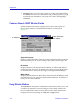
1
Generic SNMP User Guide Notice Enterasys Networks reserves the right to make changes in specifications and other information contained in this document without prior notice. The reader should in all cases consult Enterasys Networks to determine whether any such changes have been made. The hardware, firmware, or software described in this manual is subject to change without notice. IN NO EVENT SHALL CABLETRON SYSTEMS BE LIABLE FOR ANY INCIDENTAL, INDIRECT, SPECIAL, OR CONSEQUENTIAL DAMAGES WHATSOEVER (INCLUDING BUT NOT LIMITED TO LOST PROFITS) ARISING OUT OF OR RELATED TO THIS MANUAL OR THE INFORMATION CONTAINED IN IT, EVEN IF CABLETRON SYSTEMS HAS BEEN ADVISED OF, KNOWN, OR SHOULD HAVE KNOWN, THE POSSIBILITY OF SUCH DAMAGES. Virus Disclaimer Enterasys Networks has tested its software with current virus checking technologies. However, because no antivirus system is 100% reliable, we strongly caution you to write protect and then verify that the Licensed Software, prior to installing it, is virus-free with an anti-virus system in which you have confidence. Enterasys Networks makes no representations or warranties to the effect that the Licensed Software is virus-free. Copyright 2000 by Enterasys Networks . All rights reserved. Printed in the United States of America. Order Number: 9031620-04 April 2000 Enterasys Networks P.O. Box 5005 Rochester, NH 03866-5005 Cabletron Systems, SPECTRUM, BRIM, DNI, FNB, INA, Integrated Network Architecture, LANVIEW, LANVIEW Secure, Multi Media Access Center, MiniMMAC, and TRMM are registered trademarks, and Bridge/Router Interface Modules, BRIM-A100, CRBRIM-W/E, CRXMIM, CXRMIM, Desktop Network Interface, Distributed LAN Monitoring, Distributed Network Server, DLM, DNSMIM, E1000, E2000, E3000, EFDMIM, EMM-E6, EMME, EPIM, EPIM-3PS, EPIM-A, EPIM-C, EPIM-F1, EPIM-F2, EPIM-F3, EPIM-T, EPIM-T1, EPIM-X, ESXMIM, ETSMIM, ETWMIM, FDCMIM-04, FDCMIM-08, FDMMIM, FDMMIM-04, Flexible Network Bus, FOMIM, FORMIM, HubSTACK, IRBM, IRM, IRM-2, IRM-3, Media Interface Module, MicroMMAC, MIM, MMAC, MMAC-3, MMAC-3FNB, MMAC-5, MMAC-5FNB, MMAC-8, MMAC-8FNB, MMAC-M8FNB, MMAC-Plus, MRX, MRXI, MRXI-24, MultiChannel, NB20E, NB25E, NB30, NB35, NBR-220/420/620, RMIM, SecureFast Switch, SecureFast Packet Switching, SFS, SFPS, SPECTRUM Element Manager, SPECTRUM for Open Systems, SPIM-A, SPIM-C, SPIM-F1, SPIM-F2, SPIM-T, SPIM-T1, TPMIM, TPMIM-22, TPMIM-T1, TPRMIM, TPRMIM-36, TPT-T, TRBMIM, TRMM-2, TRMMIM, and TRXI are trademarks of Cabletron Systems, Inc. i AppleTalk, Apple, Macintosh, and TokenTalk are registered trademarks; and Apple Remote Access and EtherTalk are trademarks of Apple Computer, Inc. SmartBoost is a trademark of American Power Conversion ST is a registered trademark and C++ is a trademark of AT&T Banyan and VINES are registered trademarks of Banyan Systems, Inc. cisco, ciscoSystems, and AGS+ are registered trademarks; and cBus, cisco Router, CRM, IGS, and MGS are trademarks of cisco Systems, Inc. GatorBox is a registered trademark; and GatorMail, GatorMIM, GatorPrint, GatorShare, GatorStar, GatorStar GX-M, and XGator are trademarks of Cayman Systems, Inc. CompuServe is a registered trademark of CompuServe Incorporated X Window System is a trademark of Consortium, Inc. CTERM, DECnet, and ULTRIX are registered trademarks; and DEC, DEC C++, DECnet-DOS, DECstation, VAX DOCUMENT, VMA, and VT are trademarks of Digital Equipment Corporation Fore Systems, ForeRunner, and ForeRunner ASX-100 are trademarks of Fore Systems, Inc. PC/TCP is a registered trademark of FTP Software, Inc. HP OpenView is a registered trademark of Hewlett-Packard, Inc. AIX, IBM, OS/2, NetView, and PS/2 are registered trademarks; and AT, Micro Channel, PC, PC-DOS, PC/XT, Personal Computer AT, Operating System/2, Personal System/2, RISC System/6000, and Workplace Shell are trademarks of International Business Machines Corporation i960 microprocessor is a registered trademark; and Intel and Multichannel are trademarks of Intel Corporation Microsoft, MS-DOS, and Windows are registered trademarks of Microsoft Corporation Chameleon, ChameleonNFS, Chameleon 32, IPX/link, and NEWT are trademarks of NETMANAGE, Inc. NetWare and Novell are registered trademarks; and Internetwork Packet Exchange (IPX), IPX, and Network File System (NFS) are trademarks of Novell, Inc. Motif and MS are registered trademarks; and Open Software Foundation, OSF, OSF/1, and OSF/Motif are trademarks of The Open Software Foundation, Inc. Silicon Graphics and IRIS are registered trademarks; and Indigo and IRIX are trademarks of Silicon Graphics, Inc. NFS, PC-NFS, SPARC, Sun Microsystems, and Sun Workstation are registered trademarks; and OpenWindows, SPARCstation, SPARCstation IPC, SPARCstation IPX, Sun, Sun-2, Sun-3, Sun-4, Sun386i, SunNet, SunOS, SunSPARC, and SunView are trademarks of Sun Microsystems, Inc. OPEN LOOK and UNIX are registered trademarks of Unix System Laboratories, Inc. Ethernet, NS, Xerox Network Systems and XNS are trademarks of Xerox Corporation ii ANNEX, ANNEX-II, ANNEX-IIe, ANNEX-3, ANNEX-802.5, MICRO-ANNEX-XL, and MICROANNEX-ELS are trademarks of Xylogics, Inc. MAXserver and Xyplex are trademarks of Xyplex, Inc. Restricted Rights Notice (Applicable to licenses to the United States Government only.) 1. Use, duplication, or disclosure by the Government is subject to restrictions as set forth in subparagraph (c) (1) (ii) of the Rights in Technical Data and Computer Software clause at DFARS 252.227-7013. Enterasys Networks , 35 Industrial Way, Rochester, New Hampshire 03867-0505. 2. (a) This computer software is submitted with restricted rights. It may not be used, reproduced, or disclosed by the Government except as provided in paragraph (b) of this Notice or as otherwise expressly stated in the contract. (b) This computer software may be: (1) Used or copied for use in or with the computer or computers for which it was acquired, including use at any Government installation to which such computer or computers may be transferred; (2) Used or copied for use in a backup computer if any computer for which it was acquired is inoperative; (3) Reproduced for safekeeping (archives) or backup purposes; (4) Modified, adapted, or combined with other computer software, provided that the modified, combined, or adapted portions of the derivative software incorporating restricted computer software are made subject to the same restricted rights; (5) Disclosed to and reproduced for use by support service contractors in accordance with subparagraphs (b) (1) through (4) of this clause, provided the Government makes such disclosure or reproduction subject to these restricted rights; and (6) Used or copied for use in or transferred to a replacement computer. (c) Notwithstanding the foregoing, if this computer software is published copyrighted computer software, it is licensed to the Government, without disclosure prohibitions, with the minimum rights set forth in paragraph (b) of this clause. (d) Any other rights or limitations regarding the use, duplication, or disclosure of this computer software are to be expressly stated in, or incorporated in, the contract. (e) This Notice shall be marked on any reproduction of this computer software, in whole or in part. iii iv Contents Chapter 1 Introduction Using the Generic SNMP User’s Guide..................................................................... 1-1 Related Manuals............................................................................................................ 1-2 Useful Definitions ......................................................................................................... 1-2 Software Conventions .................................................................................................. 1-6 Using the Mouse .................................................................................................... 1-7 Common Generic SNMP Window Fields .......................................................... 1-8 Using Window Buttons......................................................................................... 1-8 Getting Help .................................................................................................................. 1 -9 Using On-line Help................................................................................................ 1-9 Accessing On-line Documentation...................................................................... 1-9 Getting Help from the Global Technical Assistance Center .......................... 1-10 Chapter 2 System Group Modifying the System Group Administrative Fields .............................................. 2-2 Using the Other Groups Menu ............................................................................ 2-3 Chapter 3 Viewing the Interface Group Viewing Statistics ................................................................................................... 3-3 Setting the Interface Admin Status ..................................................................... 3-4 Chapter 4 Using the Address Translation Table Editing the Address Translation Table................................................................ 4-3 Modifying Entries in the Address Translation Table................................. 4-3 Adding Entries to the Address Translation Table...................................... 4-3 Chapter 5 Viewing IP Group Statistics Setting the Time To Live Option .......................................................................... 5-5 Chapter 6 Viewing the IP Address Table v Contents Chapter 7 Using the IP Routing Table Window Modifying Entries in the IP Routing Table......................................................... 7-5 Chapter 8 Using the Net to Media Table Editing the Net to Media Table ............................................................................ 8-2 Modifying Entries in the Net To Media Table ............................................ 8-2 Adding Entries to the Net to Media Table .................................................. 8-3 Chapter 9 Viewing ICMP Group Statistics Chapter 10 Viewing TCP Group Information Chapter 11 Viewing UDP Group Information Chapter 12 Viewing EGP Group Information Displaying the EGP Group Neighbor Table Detail Window ................................ 12-3 Setting the Event Trigger..................................................................................... 12-5 Chapter 13 Viewing SNMP Group Information Disabling/Enabling Authentication Failure Traps ......................................... 13-6 Index vi Chapter 1 Introduction How to use this guide; related guides; useful definitions; software conventions; getting help Welcome to the Generic SNMP User’s Guide. This guide is a reference for using NetSight Element Manager to manage and control any SNMP-compliant devices on your network. Using the Generic SNMP User’s Guide This guide contains information about software functions which are accessed directly from the Generic SNMP icon or the System Group option available from the Device menu. Each chapter in this guide describes one major group window available for Generic SNMP management. Chapter 1, Introduction, discusses the capabilities of Generic SNMP management from NetSight Element Manager. This chapter includes a list of related guides, recommended books, and SNMP definitions. Chapter 2, System Group, describes the System Group window and its related options. The System Group window is the initial window for Generic SNMP; it displays summary and identification information about the SNMP device and provides a menu for accessing other Generic SNMP windows. Chapter 3, Viewing the Interface Group, discusses the Interface Group window, which displays the number and types of packets received at and transmitted from each interface on the monitored device. Chapter 4, Using the Address Translation Table, allows you to view and modify the mapping of IP Addresses and Physical Addresses via the Address Resolution Protocol (ARP). Chapter 5, Viewing IP Group Statistics, describes the Internet Protocol Group window and its associated fields, including the Time To Live option. Chapter 6, Viewing the IP Address Table, discusses the use of the Internet Protocol Address Table. 1-1 Introduction Chapter 7, Using the IP Routing Table Window, discusses the IP Routing Table and how to route data through your network. Chapter 8, Using the Net to Media Table, discusses the IP Address Translation Table used for mapping IP addresses to physical addresses for IP datagrams. Chapter 9, Viewing ICMP Group Statistics, discusses the Internet Control Message Protocol Group window, which summarizes ICMP message traffic. Chapter 10, Viewing TCP Group Information, describes the Transmission Control Protocol Group window, which provides TCP statistics and displays current TCP connections. Chapter 11, Viewing UDP Group Information, discusses the User Datagram Protocol Group window and UDP datagram statistics. Chapter 12, Viewing EGP Group Information, discusses the Exterior Gateway Protocol Group window, which provides information about router communications on your network. Chapter 13, Viewing SNMP Group Information, describes the SNMP Group window, which displays SNMP message traffic statistics and lets you enable and disable authentication-failure traps. Related Manuals The Generic SNMP User’s Guide is only part of a complete document set designed to provide comprehensive information about the features available to you through NetSight Element Manager. Other guides which include information related to managing Generic SNMP devices include: User’s Guide Tools Guide Remote Administration Tools User’s Guide Remote Monitoring (RMON) User’s Guide Alarm and Event Handling User’s Guide Network Troubleshooting Guide For more information about the capabilities of the SNMP device, consult the appropriate hardware documentation. Useful Definitions To help you use Generic SNMP management, we are providing a list of basic definitions that are applicable to TCP/IP networks and SNMP management. This list should not be taken as all-inclusive. 1-2 Related Manuals Introduction Active open A sequence of events occurring when an entity using an application protocol of the Internet suite (such as SMTP—the E-mail protocol; FTP—File Transfer Protocol; or Telnet—terminal service protocol) directs the Transmission Control Protocol to establish a connection over the physical medium with another user(s) of the application’s particular service. See Transmission Control Protocol (TCP), page 1-6, for more information. Address mask A bit mask that is used to select bits from an IP address for subnet addressing. The mask is 32 bits long and selects the network portion of the IP address and one or more bits of the local portion. See Subnet mask, page 1-6, for more information. Address Resolution Protocol (ARP) The Internet protocol that dynamically maps destination IP addresses to physical media (Ethernet and other) addresses. This is needed so that a datagram addressed to logical address can reach the correct physical media address. If the addresses are already mapped in transmitting device’s ARP cache (address matching tables), the datagram can be sent directly. Broadcast address A physical or IP address referring to all stations on the media. Connection A logical binding between two or more users of a service so that data can be transferred. Connection-less mode A service that has a single phase which combines both transmission control mechanisms (e.g., addressing) and data transfer. Connection-oriented mode A service that divides into three phases: establishment, in which two or more users are bound to a connection; data transfer, in which the users exchange data; and release, in which the connection is discarded. Datagram A self-contained unit of data, with an associated destination IP address and upper-layer protocol number, that is used in series to transmit a whole body of data from one device to another to the correct service layer protocol. Device A network element. Exterior Gateway Protocol (EGP) An older protocol used by gateways in a two-level internet (autonomous internet sites are connected to the Internet through core gateways). All traffic received from or transmitted between internet sites passes through the core gateway(s). Useful Definitions 1-3 Introduction Therefore, a site’s core gateway must have routing information on all networks available within the autonomous site, and must be able to pass reachability (of other Internet sites) information (using EGP) to each network gateway in that site. Flags The control bits indicating special functions for a TCP segment; for example, if the datagram is allowed to be fragmented, and if so, whether other later fragments exist. Fragment An IP datagram containing only a portion of the user-data from a larger IP datagram. A datagram will be fragmented if its size is too large to be encapsulated within the legal limits of a frame’s data field of the medium on which it is transmitted (e.g., a datagram over 1500 bytes would be fragmented if it were to be transmitted on an Ethernet network). Fragmentation The process of breaking an IP datagram into smaller parts, such that each fragment can be transmitted in whole on a given physical medium. Gateway A router (for the purposes of this manual). Internet A large collection of connected networks, primarily in the United States, running the Internet suite of protocols, also known as the DARPA Internet. Internet Control Message Protocol (ICMP) A simple protocol that provides low-level feedback that informs the internet layer about its operating status. Control messages supported by this protocol include destination unreachable; datagram discards because of timer expirations; IP header problems; discards at a destination because of a lack of resources; redirects to a gateway closer than the device’s default one; IP address reachability tests and results; delay times between transmission and reception of datagrams; and IP network address and address mask requests. Internet Protocol (IP) The network protocol offering a connectionless mode network service in the Internet Suite of protocols, in which address resolution and data transfer are completed in a single phase. Management Information Base (MIB) A collection of objects (organized in accordance with the Structure of Management Information) implemented in a network device, so that the device can be accessed and managed by a network management protocol, such as SNMP. Objects allow a device to be monitored (have information retrieved from it by a management station); to be controlled (allow remote configuration of the device, such as switching the operational state of a port); and to report abnormal events to the management station (e.g., collision threshold exceeded). 1-4 Useful Definitions Introduction Maximum transmission unit (MTU) The largest amount of user-data (e.g. the largest size of an IP datagram) that can be sent in a single frame on a particular medium. Passive open A sequence of events occurring when an entity using an application protocol of the Internet suite (e.g., SMTP, FTP, SNMP, or Telnet) informs the Transmission Control Protocol that it is willing to accept a connection to another user of the application’s particular service. See Transmission Control Protocol (TCP), page 1-6, for more information. Ports Integer quantities which identify to a transport protocol (UDP or TCP) the particular application entity (e.g., SMTP, FTP, SNMP, or Telnet) used in the transmission/reception of the data (e.g., UDP uses a port value of 161 decimal to identify SNMP data). Protocol Data Unit (PDU) A unit of information, which uses a protocol to offer a service, that is exchanged by protocol machines, A PDU usually contains protocol control information (a header identifying data to be transferred) and user data. Reassembly The process of recombining fragments, at the final destination, into the original datagram. Retransmission The process of a source TCP entity resending a unit of data while waiting for an acknowledgment of receipt by the destination TCP entity. Each time a source TCP entity transmits a segment, it starts a retransmission timer. If this timer expires before an acknowledgment from the destination, the segment will be transmitted and the timer will be restarted. Retransmission can occur only a certain number of times until the transmitting entity aborts the connection. Segment The unit used for data exchange between two entities using TCP. Socket A pairing of an IP address (destination or source) and a TCP port number. The pairing of two internet sockets (destination and source IP addresses and TCP ports) forms a connection. Simple Network Management Protocol (SNMP) The application protocol which offers network management services in the Internet suite of protocols. SNMP provides four operations for network management via a device’s MIB (its manageable objects): get (retrieval of specific management information), get-next (retrieval of management information in series by traversing the MIB), set (manipulation of management information), and trap (reports on extraordinary events at the device). Useful Definitions 1-5 Introduction Subnet A physical network within the IP network. Subnet mask A 32-bit quantity (four binary octets) that filters a destination IP address to determine whether it exists on the source IP’s subnetwork and therefore can be reached directly, or must be forwarded through a gateway or router. In the mask, all bits in the source IP address that correspond to its network portion (both site and subnet identifying bits) are set to 1, and all bits that correspond to the host portion are set to 0. The destination IP address is logically ANDed with the mask to determine its network portion. Its network portion is then compared to the network portion of the source. If the network portions match, the frame is transmitted directly; if they do not, the frame is routed. Time to live The upper bound, in seconds, that a datagram may be processed within the internet. Each time the datagram passes through the internet layer on any network device, the IP entity must decrement this field by at least one. If the field reaches zero at an intermediary device before reaching its intended destination, the datagram is discarded. Transmission Control Protocol (TCP) The Internet suite protocol which transports IP datagrams via a connection-oriented service. A connection oriented service requires that the interface layer (that responsible for transmitting datagrams on a single physical medium, e.g., Ethernet) perform connection management to find an underlying connection on which to transmit the datagram. User Datagram Protocol (UDP) The protocol offering a connectionless-mode transport service in the Internet suite of protocols. A UDP datagram contains source and destination ports, a length field, a checksum, and user-data from the upper layer protocol. Software Conventions NetSight Element Manager’s device user interface contains a number of elements which are common to most windows and which operate the same regardless of the window in which they appear. A brief description of some of the most common elements appears below. NOTE 1-6 In accordance with Year 2000 compliance requirements, NetSight Element Manager displays and allows you to set all dates with four-digit year values. Software Conventions Introduction Using the Mouse This document assumes you are using a Windows-compatible mouse with two buttons; if you are using a three-button mouse, you should ignore the operation of the middle button when following procedures in this document. Procedures within the NetSight Element Manager document set refer to these buttons as follows: Left Mouse Button Right Mouse Button Figure 1-1. Mouse Buttons For many mouse operations, this document assumes that the left (primary) mouse button is to be used, and references to activating a menu or button will not include instructions about which mouse button to use. However, in instances in which right (secondary) mouse button functionality is available, instructions will explicitly refer to right mouse button usage. Also, in situations where you may be switching between mouse buttons in the same area or window, instructions may also explicitly refer to both left and right mouse buttons. Instructions to perform a mouse operation include the following terms: • Pointing means to position the mouse cursor over an area without pressing either mouse button. • Clicking means to position the mouse pointer over the indicated target, then press and release the appropriate mouse button. This is most commonly used to select or activate objects, such as menus or buttons. • Double-clicking means to position the mouse pointer over the indicated target, then press and release the mouse button two times in rapid succession. This is commonly used to activate an object’s default operation, such as opening a window from an icon. Note that there is a distinction made between “click twice” and “double-click,” since “click twice” implies a slower motion. • Pressing means to position the mouse pointer over the indicated target, then press and hold the mouse button until the described action is completed. It is often a pre-cursor to Drag operations. Software Conventions 1-7 Introduction • Dragging means to move the mouse pointer across the screen while holding the mouse button down. It is often used for drag-and-drop operations to copy information from one window of the screen into another, and to highlight editable text. Common Generic SNMP Window Fields Similar descriptive information is displayed in text boxes at the top of most device-specific windows in NetSight Element Manager, as illustrated in Figure 1-2. System Description MAC Address IP Address Figure 1-2. Sample Window Showing Informational Text Boxes System Description Displays a textual description of the device. This description usually includes the full name of the device, the version number of the system’s hardware type, the software operating-system, and networking software. IP Address Displays the device’s IP (Internet Protocol) Address; this will be the IP address used to define the device icon. IP addresses are assigned via Local Management for the SNMP device; they cannot be changed via NetSight Element Manager. MAC Address Displays the manufacturer-set MAC address associated with the IP address used to define the device icon created via NetSight Element Manager. This address is factory-set and cannot be altered. Using Window Buttons The Cancel button that appears at the bottom of most windows allows you to exit a window and terminate any unsaved changes you have made. You may also have to use this button to close a window after you have made any necessary changes and set them by clicking on an OK, Set, or Apply button. 1-8 Software Conventions Introduction An OK, Set, or Apply button appears in windows that have configurable values; it allows you to confirm and SET changes you have made to those values. In some windows, you may have to use this button to confirm each individual set; in other windows, you can set several values at once and confirm the sets with one click on the button. The Help button brings up a Help window with information specific to the current window. For more information, see Getting Help, page 1-9. The command buttons, for example Bridge, launch a menu listing the windows, or commands available for that topic. Any menu topic followed by … (three dots)—for example Statistics…— launches a window associated with that selection. Getting Help This section describes different methods of getting help for questions or concerns you may have while using NetSight Element Manager. Using On-line Help You can use the Generic SNMP window Help buttons to obtain information specific to the device. When you click on a Help button, a window will appear which contains context-sensitive on-screen documentation that will assist you in the use of the windows and their associated command and menu options. Note that if a Help button is grayed out, on-line help has not yet been implemented for the associated window. NOTE All of the online help windows use the Microsoft Windows help facility. If you are unfamiliar with this feature of Windows, you can select Help from the Windows Start menu, or Help —> How to Use Help from the primary NetSight Element Manager window. Accessing On-line Documentation The complete suite of documents available for NetSight Element Manager can be accessed via a menu option from the primary window menu bar: Help —> Online Documents. If you installed the documentation component, selecting this option will launch Adobe’s Acrobat Reader and a menu file which provides links to all other available documents. TIP Getting Help If you have not yet installed the documentation, the Online Documents option will not be able to access the menu file; in order to activate this option, you must run setup.exe again to install the documentation component. See the Installation Guide for details. 1-9 Introduction Getting Help from the Global Technical Assistance Center If you need technical support related to NetSight Element Manager, contact the Global Technical Assistance Center via one of the following methods: By phone: (603) 332-9400 24 hours a day, 365 days a year By fax: (603) 337-3075 By mail: Enterasys Technical Support 35 Industrial Way Rochester, NH 03867 By e-mail: [email protected] FTP: ftp.ctron.com (134.141.197.25) Login Password By BBS: Modem Setting anonymous your email address (603) 335-3358 8N1: 8 data bits, 1 stop bit, No parity Send your questions, comments, and suggestions regarding NetSight documentation to NetSight Technical Communications via the following e-mail address: [email protected] To locate product specific information, refer to the Enterasys Web site at the following address: http://www.enterasys.com 1-10 Getting Help Chapter 2 System Group The System Group window; using the Other Groups menu The System Group window provides basic information about the type of device currently being monitored, including the System Object ID and Uptime, as well as administrative information, including the device’s name, location, contact person, and the level of Open Systems Interconnection (OSI) services. You can access all other Generic SNMP windows from the System Group window. To open the System Group window from the Device View or Chassis View window of any SNMP-compliant device: 1. Select Device—>System Group in the Chassis View or Device View menu bar. The System Group window as shown in, Figure 2-1, opens. Figure 2-1. System Group Window 2-1 System Group The System Group window displays the following fields: Object ID Displays the unique identifier of the device being managed. This value is allocated within the SMI enterprises subtree (1.3.6.1.4.1). Uptime Displays the amount of time that the device has been running since the network management portion of the system was last initialized. This is converted from hundredths of a second (as stored in the device MIB) into a more useful days, HH:MM:SS format. Contact Displays a text field which you can use to enter the name and/or telephone number of the person responsible for the device. Name Displays a text field which you can use to assign a name for the device. Location Displays a text field which you can use to describe the node’s physical location. Services Displays the level of OSI (Open Systems Interconnection) services supported by the device, examples of which are given in Figure 2-2. Physical Layer……………………………….e.g. repeaters Datalink/Subnetwork Layer………………e.g. bridges Internet Layer…………………………..e.g. IP gateways End-to-end Layer…………………………….e.g. IP hosts Applications Layer……………………..e.g. mail relays Figure 2-2. Examples of OSI Service Layers Modifying the System Group Administrative Fields If your device’s firmware supports MIB II, you can modify the Contact, Name, and Location fields. 1. To modify the Contact field: a. Click the I-bar cursor ( ) to the right of the Contact field. The Contact text box opens, Figure 2-3. 2-2 Modifying the System Group Administrative Fields System Group Figure 2-3. Contact Text Box b. Type in the new contact information in the text box; then click on OK. 2. To modify the Name field: a. Click the I-bar cursor ( ) to the right of the Name field. The Name text box opens, Figure 2-4. Figure 2-4. Name Text Box b. Type in the new name in the text box; then click on OK. 3. To modify the location field: a. Click on the I-bar cursor ( ) to the right of the Location field. The Location text box opens, Figure 2-5. Figure 2-5. Location Text Box b. Type in the new location in the text box; then click on OK. Using the Other Groups Menu The Other Groups button displays a menu (Figure 2-6), which lets you select other Generic SNMP windows supported by the device. Modifying the System Group Administrative Fields 2-3 System Group Figure 2-6. Other Group Menu To access the Other Groups drop-down menu via the System Group window: 1. Click on the Other Groups button. The Other Groups drop-down menu displays, as shown in Figure 2-6. Non-supported options will be grayed-out. 2. Click on the desired option. The appropriate window opens. 2-4 Modifying the System Group Administrative Fields Chapter 3 Viewing the Interface Group Viewing interface statistics; using the Admin/Status option and the Last Change field The Interface Group window displays statistics for each interface on the device. The port type is displayed for each interface along with the statistics associated with that interface. Use the scroll bar to display the other available interfaces; the interface number and the total number of interfaces on the device are displayed above the scroll bar (e.g., 1 of 27). Statistics are gathered for network activity levels occurring at the physical and data-link layers. These statistics reflect the following types of packets being transmitted and received: • • • • • • • Unicasts Multicasts Discarded Packets Error Packets Received Packets with unknown protocols Packets waiting to be transmitted Bytes To open the Interface Group window from the System Group window: 1. Click on the Other Groups button. The Other Groups drop-down menu displays. 2. Click on Interface Group. The Interface Group window, Figure 3-1, opens. 3-1 Viewing the Interface Group Figure 3-1. Interface Group Window The following fields are non-statistical interface descriptions fields: Address The interface’s physical address (ifPhysAddr) at the protocol layer immediately below the network layer in the protocol stack. For interfaces which do not have such an address (e.g., a serial line), this object should contain an octet string of zero length. Interface Type The type of interface (ifType), distinguished according to the physical/link protocol(s) immediately below the network layer in the protocol stack. MIB-II defines 32 different interface types, including ethernet-csmacd, fddi, iso88025-tokenRing, and softwareLoopBack. MTU (Maximum Transfer Unit) The size of the largest datagram which can be transmitted or received on the interface (specified in octets), according to the ifMtu. For interfaces that are used for transmitting network datagrams, this is the size of the largest network datagram that can be sent on the interface. Frames that exceed the MTU are discarded. Speed An estimate of the interface’s current bandwidth in bits per second, according to the ifSpeed. For interfaces which do not vary in bandwidth or for those where no accurate estimation can be made, this object should contain the nominal bandwidth. 3-2 Viewing the Interface Group Last Change The Last Change field (bottom of the window) displays the date and the time since the system was last reinitialized. NOTE In accordance with Year 2000 compliance requirements, NetSight Element Manager displays and allows you to set all dates with four-digit year values. Viewing Statistics The following statistics are collected from received and transmitted packets. Unicast The number of subnetwork unicast (sent to one station) packets received from a higher-layer protocol, according to the ifInUcastPkts. The number of subnetwork unicast (sent to one station) packets delivered to a higher-layer protocol, according to the ifOutUcastPkts. Multicast The number of non-unicast (i.e., subnetwork-broadcast or subnetwork multi-cast) packets received from a higher-layer protocol, according to the ifInNUcastPkts. The number of non-unicast (i.e., subnetwork-broadcast or subnetwork multi-cast) packets delivered to a higher-layer protocol, according to the ifOutNUcastPkts. A multicast transmission is simultaneously sent to more than one station at a time. Discarded The number of inbound packets which were chosen to be discarded even though no errors had been detected to prevent their being transmitted, according to the ifInDiscards. The number of inbound or outbound packets which were chosen to be discarded even though no errors had been detected to prevent their being deliverable, according to the ifOutDiscards. Discarding good packets indicates a very busy network (e.g. discarding packets to free up buffer space). If a device routinely discards packets it usually indicates that network traffic is overwhelming the device. Error The number of inbound packets that contained errors preventing them from being delivered to a higher-layer protocol, according to the ifInErrors. The number of outbound packets that could not be transmitted because of errors, according to the ifOutErrors 3-3 Viewing the Interface Group Unknown Protocol (Received Packets only) The number of packets received via the interface which were discarded because of an unknown or unsupported protocol, according to the ifInUnknownProtos. Transmit Queue Size (Transmitted Packets only) The length of the output packet queue (in packets), according to the ifOutQLen. The amount of device memory devoted to buffer space, and the traffic level on the target network determine how large the output packet queue can grow before the device begins to discard packets. Bytes Received Displays the total number of inbound bytes. Bytes Transmitted Displays the total number of bytes transmitted onto the network. Specific MIB Def. Displays a MIB definition of the media being used to realize that segment’s interface. A MIB definition is only available for devices whose firmware supports MIB-II. Setting the Interface Admin Status The Admin Status button lets you enable, disable, or test the current interface. The operational states of these three options are: Enable The interface will be ready to pass packets. Disable The interface will be in a closed state. Test The interface will be in some test mode and no operational packets can be passed. To use the Admin Status button: 1. Click on the Admin Status button. The Administration Status drop-down menu displays. 2. Click on the appropriate option: Enable, Disable, or Test. If you choose Disable, a warning window opens to indicate that you may lose access to the device. 3. Click OK to disable the interface, or Cancel to nullify the disable command. The current interface will now begin operating in the state you have selected. 3-4 Chapter 4 Using the Address Translation Table The Address Translation Table window; editing the Address Translation Table The Address Translation Table utilizes ARP (Address Resolution Protocol) to translate IP addresses into Physical addresses. ARP is used to achieve mapping between IP addresses which are 32 bits in length and Physical addresses which are 48 bits in length. The Address Translation Table window lets you view and modify the translation of an interface’s IP address to its corresponding Physical address. You may want to change the mapping if you have installed new hardware in an SNMP device; the Physical address has changed, but the logical IP address remains the same. To open the Address Translation Table from the System Group window: 1. Click on the Other Groups button. The Other Groups drop-down menu displays. 2. Click on Address Translation. The Address Translation Table window, Figure 4-1, opens. 4-1 Using the Address Translation Table Figure 4-1. Address Translation Table Window The display panel (upper section) of the Address Translation window lists the addresses associated with the interface. The Values set for section lets you add and modify entries in the panel. Interface Index The network interfaces on which this system can send and receive IP datagrams. Physical Address The media dependent MAC addresses that have been detected in datagrams processed through the indicated Interface Index. Note that if datagrams had been forwarded through a router interface before being received at the monitored Interface Indices, more than one IP address will be mapped to the same physical address (that of the router port forwarding datagrams). IP Address The logical network addresses that correspond to the physical addresses. 4-2 Using the Address Translation Table Editing the Address Translation Table You can modify existing entries in, or add new entries to the Address Translation Table. Modifying Entries in the Address Translation Table By modifying an entry in the Address Translation Table you will change the mapping that was discovered by the ARP process. 1. Click on an entry in the Address Translation Table. That entry’s corresponding values for its Port Number, Physical Address, and IP address display in the Values set for area. 2. Enter the desired changes in the Physical Address field within the Values set for area. 3. Click on Set. Status information displays above the command buttons and a confirmation window opens; if the set succeeded, the changes appear in the display panel. NOTE When an entry is highlighted the interface description is displayed in the Values for Set section of the window, (e.g., Ctron SEHI EnetPort). Adding Entries to the Address Translation Table 1. Click on Clear. This allows you to enter values in the Values set for section. 2. Enter the Port Number, Physical Address, and IP Address in the appropriate fields. 3. Click on Set. Status information displays above the command buttons and a confirmation window opens; if the set succeeded, the new entry appears in the display panel. NOTE If the Physical Address is entered in an incorrect format, an “Invalid Ethernet Address” message displays. Enter the address in the correct XX-XX-XX-XX-XX-XX hexadecimal format. If the IP Address is entered in an incorrect format, an “Invalid IP Address” message displays. Enter the address in the correct XXX-XXX-XXX-XXX format. 4-3 Using the Address Translation Table 4-4 Chapter 5 Viewing IP Group Statistics The IP Group window; using the Time To Live option The Internet Protocol (IP) is the protocol used in the Internet layer. Each IP datagram contains identifying information such as the datagram’s originator, the datagram’s length, the format used (version), and the quality of service. Each medium has a maximum size data field used to encapsulate an IP datagram (Maximum Transmit Unit or MTU). When a local IP entity (the device) wishes to send a datagram larger than the allowable maximum size, it must first fragment the datagram prior to transmission. The IP entity checks to see if the flags field in the datagram permits fragmentation. (If it does not, the datagram is discarded.) It then generates two or more fragments that contain a portion of the user-data from the original datagram. These fragments are reassembled at the destination IP address. If they arrive out of order (since they may be routed over different paths), they are held (buffered) until all fragments of the original datagram have arrived. Should the fragments become lost or corrupted during transmission, then they are discarded. The IP Group window provides a statistical breakdown of the number of datagrams received by, and transmitted from the device. Also included are the various types of fragmented and reassembled datagrams. To open the IP Group window from the System Group window: 1. Click on the Other Groups button. The Other Groups drop-down menu displays. 2. Click on IP Group. The IP Group window, Figure 5-1, opens. 5-1 Viewing IP Group Statistics Figure 5-1. IP Group Window Forwarding State Displays whether this entity is acting as an IP gateway in respect to the forwarding of datagrams received by — but not addressed to — this entity, according to the ipForwarding. IP gateways forward datagrams; IP hosts do not (except those source-routed via the host). For some managed nodes, this object may take on only a subset of the values possible. It is appropriate for an agent to return a ‘badValue’ response if a management station attempts to change this object to an inappropriate value. The IP Group window displays the following statistics: Received Datagrams Total The total number of input datagrams received from interfaces, including those received in error, according to ipInReceives. 5-2 Header Errors The number of input datagrams discarded due to errors in their IP headers, including bad checksums, version number mismatch, other format errors, time-to-live exceeded, errors discovered in processing their IP options, etc. This field displays ipInHdrErrors. Address Errors The number of input datagrams discarded because the IP address in their IP header’s destination field was not a valid address to be received at this entity. This count includes invalid addresses (e.g., 0.0.0.0) and addresses of unsupported Classes (e.g., Class E). For entities which are not IP Gateways and therefore do not forward Viewing IP Group Statistics datagrams, this counter includes datagrams discarded because the destination address was not a local address. This field displays the ipInAddrErrors. Forwarded The number of received datagrams for which this entity was not their final IP destination, as a result of which an attempt was made to find a route to forward them to that final destination. In entities which do not act as IP Gateways, this counter will include only those packets which were Source-Routed successfully via this entity, and the Source-Route option processing was successful. This field displays the ipForwDatagrams. Unknown Protocol The number of locally-addressed datagrams received successfully but discarded because of an unknown or unsupported protocol. This field displays the ipInUnknownProtos. Discarded The number of input IP datagrams for which no problems were encountered to prevent their continued processing, but which were discarded (e.g., for lack of buffer space). This counter does not include any datagrams discarded while awaiting reassembly. This field displays the ipInDiscards. Delivered The total number of input IP datagrams successfully delivered to IP user-protocols (including ICMP), according to the ipInDelivers. Transmitted Datagrams Total The total number of input datagrams successfully delivered to IP user-protocols (including ICMP), according to the ipOutRequests. Discarded The number of output IP datagrams for which no problem was encountered to prevent their transmission to their destination, but which were discarded (e.g., for lack of buffer space). This counter would include datagrams counted in ipForwDatagrams if any such packets met this (discretionary) discard criterion. This field displays the ipOutDiscards. This counter indicates that the device is tossing away valid datagrams, indicating that the destination network is seriously overloaded, or that the device itself is experiencing problems (evidenced by the failing read-write buffer). If the device discards a datagram, it occurs after the device increments the Fwd Datagrams counter and passes the datagram to the transmit buffer. 5-3 Viewing IP Group Statistics No Route The number of IP datagrams discarded because no route could be found to transmit them to their destination. This counter includes packets counted in ipForwDatagrams which meet this ‘no-route’ criterion, and any datagrams a host cannot route because all of its default gateways are down. This field displays the ipOutNoRoutes. Datagram Fragmentation Datagrams The number of IP datagrams that have been successfully Fragmented fragmented at this entity, according to the ipFragOKs. A station fragments a datagram if the datagram is too large to fit within a physical frame. Discarded The number of IP datagrams that have been discarded because they needed to be fragmented at this entity but could not be (e.g., because their Don’t Fragment flag was set). This field displays the ipFragFails. Fragments Created The number of IP datagram fragments that have been generated as a result of fragmentation at this entity, according to the ipFragCreate. Datagram Reassembly Fragments Recvd The number of IP fragments received which needed to be reassembled at this entity, according to the ipReasmReqds. 5-4 Datagrams Reassembled The number of IP datagrams successfully reassembled, according to the ipReasmOKs. If a datagram is fragmented for transmission, the receiving station is responsible for reassembling the fragments. If the receiving station receives all fragments within the time period specified by the reassembly timer, it increments the Reasm OKs timer. Reassembly Failures The number of failures detected by the IP reassembly algorithm. Note that this is not necessarily a count of discarded IP fragments since some algorithms (notably the algorithm in RFC 815) can lose track of the number of fragments by combining them as they are received. This field displays the ipReasmFails. Reassembly TimeOut The maximum number of seconds which received fragments are held while they are awaiting reassembly at this entity, according to the ipReasmTimeout. IP attempts to encapsulate each datagram in a single physical frame. If it cannot do so, it fragments the datagram into multiple physical frames, The receiving station starts a reassembly timer when it receives the first fragment. If the timer expires before all fragments arrive, the device discards the fragments already received. The reassembly timer is a read-only attribute. Viewing IP Group Statistics Setting the Time To Live Option When a device transmits an IP datagram, it sets the amount of time, in seconds, the datagram is allowed to exist, by setting the Time-To-Live (TTL) field located in the datagram’s header. This eliminates the possibility that a datagram could travel around a network forever. If the TTL timer expires before the datagram reaches its destination, the datagram is discarded and an error message is returned to the original sending device. Each gateway along the datagram’s path from source to destination decrements the TTL field by 1 when it processes the datagram’s header field. The gateway also records the local time of datagram arrival and decrements the TTL timer by the number of seconds the datagram remained in the gateway awaiting service. To set the Time To Live Option: 1. Click on the I-bar cursor ( ) to the right of the Time To Live text box. The IP Group Time To Live text box, Figure 5-2, opens. Figure 5-2. Time To Live Text Box 2. Enter the new default Time To Live (in seconds) in the text box. The allowable time values are 0 to 255. 3. Click OK. The new default Time To Live displays in the text box. This indicates the number of seconds a datagram can continue to exist on the network. Any datagram that exceeds this limit will be discarded. 5-5 Viewing IP Group Statistics 5-6 Chapter 6 Viewing the IP Address Table The IP Address Table window The IP Address Table displays the IP Addresses and the subnet masks for each of the device’s interfaces. In addition, you can see whether network broadcasts will be sent with 1s or 0s in the host portion of the IP Address, and the maximum size fragment that can be reassembled. To open the IP Address Table window from the System Group window: 1. Click on the Other Groups window. The Other Groups drop-down menu displays. 2. Click on IP Address Table. The IP Address Table window, Figure 6-1, opens. Figure 6-1. IP Address Table Window 6-1 Viewing the IP Address Table The display panel of the IP Address Table window contains address information for each entry in the table. If there are more entries in the IP Address Table than can fit in the display panel, scroll bars displays so that you can view the remaining entries in the table. Interface Index The number of each interface on which this system can send and receive IP datagrams. IP Address The addressing information for one of this entity’s IP addresses, according to the ipAddrEntry. A device with multiple interfaces, such as a bridge, can have multiple IP addresses. Subnet Mask The subnet mask associated with the IP address of this entry, according to the ipAdEntNetMask. The value of the mask is an IP address with all the network bits set to 1 and all the hosts bits set to 0. A subnet mask identifies the network and host portion of a device’s IP address. Octets in a dotted decimal notation subnet mask set to 255 indicate a network identifier. You set a device’s subnet mask in the IP Routing Table. Broadcast Address The value of the least-significant bit in the IP broadcast address used for sending datagrams in the (logical) interface associated with the IP address of this entry, according to the ipAdEntBcastAddr. For example, when the Internet standard all-ones broadcast address is used, the value will be 1. This value applies to both the subnet and network broadcast addresses used by the entity on this (logical) interface. A broadcast address has a hostid (the portion of the IP address that identifies the host) with all bits set to 1 or 0. This field displays whether all 1s or 0s will be used to address IP packets that are sent as network broadcasts. A broadcast reaches all hosts on the network. Reassemble Max Size The size of the largest IP datagram which this entity can reassemble from incoming IP fragmented datagrams received on this interface, according to the ipAdEntReasmMaxSize. The maximum size of a complete IP datagram is 65,535 bits. Fields in the lower left section display the following information: Number of Table Items The number of IP address entries in the IP Address Table. Interface Description The Interface Description (ifDescription) for the currently selected interface in the IP address panel. 6-2 Chapter 7 Using the IP Routing Table Window IP Routing Table window; modifying the routing information; The IP Routing Table provides a way for devices to exchange data. Your local IP device must determine the next “hop” or stop on the data route. If the destination is on the same IP network, then the next hop is the destination IP address. Otherwise, the next stop is a router (gateway) on the same IP network as the local device. The router is determined to be “closer” to the destination device. The IP Routing Table window lets you view and modify routing information for each interface. To open the IP Routing Table window from the System Group window: 1. Click the Other Groups button. The Other Groups drop-down menu displays. 2. Click on IP Routing Table. The IP Routing Table window, Figure 7-1, opens. 7-1 Using the IP Routing Table Window Figure 7-1. IP Routing Table Window The IP Routing Table displays the following fields: Destination The destination IP address of this route, according to the ipRouteDest. An entry with a value of 0.0.0.0 is considered a default route. Multiple routes to a single destination can appear in the table, but access to such multiple entries is dependent on the table-access mechanisms defined by the network management protocol in use. A gateway determines the route in which to send an IP datagram by checking its IP Routing Table. Each entry in the table represents a different route to a gateway. The routing table points to gateways that can be reached across a single network. Next Hop The IP address of the next hop of this route, according to the ipRouteNextHop. In the case of a route bound to an interface which is realized via a broadcast media, the value of this field is the agent’s IP address on that interface. If the datagram’s ultimate destination is on a directly connected network, the next hop IP address is the same as the datagram’s destination IP address. The next hop specifies a gateway that can route the datagram closer to its final destination. Route Age The number of seconds since this route was last updated or otherwise determined to be correct, according to the ipRouteAge. No semantics of ‘too old’ can be implied except through knowledge of the routing protocol by which the route was learned. 7-2 Using the IP Routing Table Window Route Mask Indicates the mask to be logical-ANDed with the destination address before being compared to the value in the ipRouteDest field, according to the ipRouteMask. For those systems that do not support arbitrary subnet masks, an agent constructs the value of the ipRouteMask by determining whether the value of the corresponding ipRouteDest field belongs to a class-A, B, or C network, and then uses one of the following: Mask 255.0.0.0 255.255.0.0 255.255.255.0 Network class-A class-B class-C If the value of the ipRouteDest is 0.0.0.0 (a default route), then the mask value is also 0.0.0.0. It should be noted that all IP routing subsystems implicitly use this mechanism. When a host or gateway receives an IP datagram, it must determine if the datagram’s final destination is on the local network or on another network. The IP software does not need to examine the entire IP address to make this local/remote network decision; it only needs to compare the network portion of the received datagram’s IP address with the network mask. If the datagram is destined for a host on the local net, the datagram is delivered directly; otherwise, it is sent to the IP address specified in the “next hop” field of the routing table. Route Interface The index value (ipRouteIfIndex) which uniquely identifies the local interface through which the next hop of this route should be reached. The interface identified by a particular value of this index is the same interface as identified by the same value of ifIndex. Route Protocol The routing mechanism via which this route was learned. Inclusion of values for gateway routing protocols is not intended to imply that hosts should support those protocols, according to the ipRouteProto. • • • • • • • • • • • • • • other (1)—none of the following local (2)—non-protocol information, e.g., manually configured entries netmgmt (3)—set via a network management protocol icmp (4)—obtained via ICMP, e.g., Redirect egp (5) ggp (6) hello (7) rip (8) is-is (9) es-is (10) ciscoIgrp (11) bbnSpflgp (12) ospf (13) bgp (14) 7-3 Using the IP Routing Table Window Route Info A reference to MIB definitions specific to the particular routing protocol which is responsible for this route, as determined by the value specified in the route’s ipRouteProto value. If this information is not present, its value should be set to the OBJECT IDENTIFIER {0,0}, which is a syntactically valid object identifier, and any conformant implementation of ASN.1 and BER must be able to generate and recognize this value. This field displays the ipRouteInfo. Route Metrics Displays the Routing Metrics for the route. Metrics may be Primary or Alternate as explained below: Route Metric 1 The primary routing metric for this route, according to the ipRouteMetric1. The semantics of this metric are determined by the routing-protocol type specified in the route’s ipRouteProto value. If this metric is not used, its value should be set to -1. Route Metrics 2-5 An alternate routing metric for this route, according to the ipRouteMetric2, ipRouteMetric3, ipRouteMetric4, and ipRouteMetric5 (the fifth route metric is available only for devices supporting MIB-II). The semantics of this metric are determined by the routing-protocol type specified in the route’s ipRouteProto value. If this metric is not used, the value should be set to -1. Route Type The type of route, according to the ipRouteType. To change the Route Type, click on the appropriate option button: • • • • Other (1)None of the following. Invalid (2)An invalidated route. Direct (3)Route to directly connected (sub)network. Indirect (4)Route to a non-local host/network/subnetwork. The values direct (3) and indirect (4) refer to the notion of direct and indirect routing in the IP architecture. Setting this object to the value of invalid (2) has the effect of invalidating the corresponding entry in the ipRouteTable object. It effectively disassociates the destination identified with said entry from the route identified with said entry. It is an implementation-specific matter as to whether the agent removes an invalidated entry from the table. Accordingly, management stations must be prepared to receive tabular information from agents that correspond to entries not currently in use. Proper interpretation of such entries requires examination of the relevant ipRouteType object. Fields not supported by the device’s firmware will display a value of “Not avail in device”. NOTE 7-4 Using the IP Routing Table Window Modifying Entries in the IP Routing Table 1. Click in the Destination field, enter the desired destination IP address. 2. Click in the Next Hop field, enter the IP address that you want to specify as the next hop of the route. 3. Click in the Route Metrics field(s), enter the desired metric value(s). 4. Click the desired option in the Route Type section. 5. Click Apply to accept the changes, or Cancel to exit the IP Routing Table window without saving changes. NOTE The IP Routing Table window allows you to scroll through each entry in the table by using the Prev and Next buttons at the bottom of the window. As you click on Prev and Next to view each entry of the routing table, you can view the interface number associated with that route entry in the Route Interface list box in the middle of the window. When you get to the first or last entry, the Prev or Next button will be grayed-out, respectively. If you have made a change to a route entry, and then click on Prev, Next, a message will appear asking if you want to set the device with those changes. Click Yes to effect the changes or No to disallow any changes that have been made. 7-5 Using the IP Routing Table Window 7-6 Chapter 8 Using the Net to Media Table The Net To Media Table window; modifying an entry The Net to Media Table is used by MIB-II devices to map IP addresses to physical addresses when transmitting an IP datagram for devices on each network segment directly connected to the monitored device. The table includes the media type for each port interface, as well as the map type through which the table entry is obtained. MIB-I devices do not support the Net to Media Table. To open the Net to Media Table window from the System Group window: 1. Click on the Other Groups button. The Other Groups drop-down menu displays. 2. Click NetToMedia Table. The Net to Media Table window, Figure 8-1, opens. Figure 8-1. Net to Media Table Window 8-1 Using the Net to Media Table The display panel (top section) of the Net to Media Table displays address information for the associated interface. The Values set for section lets you modify entries in the display panel and make static entries to the ARP cache. Interface Index The interface on which this entry’s equivalence is effective, according to the ipNetToMediaIfIndex. The interface identified by a particular value of this index is the same interface as identified by the same value of ifIndex. Physical Address The physical address, according to the ipNetToMediaPhysAddress. You can edit the physical address; however, changing a physical address in the Net to Media table does not change the device’s physical address. It lets you edit the monitored device’s knowledge of the relationship between a physical and an IP address. IP Address IP Address corresponding to the media-‘physical’ address, according to the ipNetToMediaNetAddress. Mapping Type The type of mapping, according to the ipNetToMediaType. other (1) invalid (2) dynamic (3) static (4) none of the following. invalidated mapping; the address is present but the entry cannot be used. address mapping is learned through ARP broadcasts. an entry has been manually added to the permanent database. Setting this object to the value of invalid (2) has the effect of invalidating the corresponding entry in the ipNetToMediaTable. It effectively disassociates the interface identified with an entry from the mapping identified with that entry. It is an implementation-specific matter as to whether the agent removes an invalidated entry from the table. Management stations must be prepared to receive tabular information from agents that correspond to entries not currently in use. Proper interpretation of such entries requires examination of the relevant ipNetToMediaType object. Editing the Net to Media Table You can add new entries to and modify existing entries in the Net to Media Table. Modifying Entries in the Net To Media Table 1. Click on an entry in the Net To Media Table. That entry’s corresponding values for its Port Number, Physical Address, IP address, and Mapping Type, displays in the Values set for area. 8-2 Using the Net to Media Table 2. Enter the desired changes in the Physical Addr field within the Values set for area. 3. Click on the option button corresponding to the way you want that entry mapped into the database (other, invalid, dynamic, or static). Selecting invalid as the mapping type disables the selected translation entry. 4. Click Set. Status information displays above the command buttons and a confirmation window opens; if the set succeeded, the changes displays in the list. NOTE When an entry is highlighted the interface description is displayed in the Values set for section of the window, (e.g., Ctron SEHI EnetPort). Adding Entries to the Net to Media Table You can make static entries to the ARP cache; static entries remain in the ARP cache until you remove them. 1. Click Clear. This allows you to enter values in the Values set for section. 2. Enter the port number, physical address, and IP address in the appropriate fields. 3. Click on the option button corresponding to the way you want that entry mapped into the database (other, invalid, dynamic, or static). 4. Click Set. Status information displays above the command buttons and a confirmation window opens; if the set succeeded, the new entry displays in the list. NOTE If the Physical Address is entered in an incorrect format, an “Invalid Ethernet Address” message opens. Enter the address in the correct XX-XX-XX-XX-XX-XX hexadecimal format. If the IP Address is entered in an incorrect format, an “Invalid IP Address” message opens. Enter the address in the correct XXX-XXX-XXX-XXX format. 8-3 Using the Net to Media Table 8-4 Chapter 9 Viewing ICMP Group Statistics The ICMP Group window ICMP (Internet Control Message Protocol) is the Internet Protocol mechanism used by network devices to determine if a destination is reachable and to notify other devices about delivery problems. Using PING (Packet Internet Groper), an ICMP echo request packet is sent to an IP address and awaits a reply. This provides a means to test the availability of devices and routes on the network (from the local network device to a remote network device). The ICMP Group window displays statistics for the ICMP datagram traffic transmitted and received by the device, which provides information on how your device is performing at the Internet layer. To open the ICMP Group window from the System Group window: 1. Click on the Other Groups button. The Other Groups drop-down menu displays. 2. Click on ICMP Group. The ICMP Group window, Figure 9-1, opens. 9-1 Viewing ICMP Group Statistics Figure 9-1. ICMP Group Window The ICMP Group window displays the following message statistics: ICMP Received Message Statistics Total Messages The total number of ICMP messages which the entity received, according to the icmpInMsgs. This counter includes all those counted by icmpInErrors. Errors The number of ICMP messages which the entity received but determined as having ICMP-specific errors (bad ICMP checksums, bad length, etc.), according to the icmpInErrors. Destination Unreachable The number of ICMP Destination Unreachable messages received, according to the icmpInDestUnreachs. A gateway issues a destination unreachable message when it cannot deliver a datagram due to one of the following causes: • • • • • • • 9-2 network, host, protocol, or port was unreachable fragmentation was necessary but disallowed by the “don’t fragment” bit source route failed destination network or host unknown source host isolated communication with destination network or host administratively prohibited network or host unreachable for type of service Viewing ICMP Group Statistics Time Exceeded The number of ICMP Time Exceeded messages received, according to the icmpInTimeExcds. When a device discards a datagram because the time-to-live counter (hop count) reached zero, or because the reassembly counter expired while waiting for fragments, a router sends a time exceeded message to the station that transmitted the original datagram. A time exceeded message can indicate an excessively long route from source to destination, or it could indicate a circular route due to errors in the routing tables. For fragmented packets, the receiving station starts its reassembly timer when it receives the first fragment of a fragmented datagram. If the timer expires before all fragments are received, the station discards the fragments it has already received, and transmits a time exceeded message. Parameter Problem The number of ICMP Parameter Problem messages received, according to the icmpInParmProbs. A parameter problem message indicates that a datagram was discarded due to a problem not covered by any of the previous messages. Source Quench The number of ICMP Source Quench messages received, according to the icmpInSrcQuenchs. A router issues a source quench message when network traffic overwhelms the router’s buffering capability. A source quench message instructs a host to slow its current rate of datagram transmission. Redirect The number of ICMP Redirect messages received, according to the icmpInRedirects. When a host transmits, it uses minimal routing information and it learns new routes from routers. A router that detects a host using an inefficient route sends a redirect message that contains new routing information. Echo Request The number of ICMP Echo (request) messages received, according to the icmpInEchos. An echo request tests connectivity between two network devices. Echo Reply The number of ICMP Echo Reply messages received, according to the icmpInEchoReps. When a device receives an echo request, it responds by issuing an echo reply. Timestamp Request The number of ICMP Timestamp Request messages received, according to the icmpInTimeStamps. Timestamp Reply The number of ICMP Timestamp Reply messages received, according to the icmpInTimeStampReps. To synchronize system clocks, a machine can issue a timestamp request to another machine. The destination machine then issues a timestamp reply message that includes the system time. 9-3 Viewing ICMP Group Statistics Address Mask Request The number of ICMP Address Mask Request Messages received, according to the icmpInAddrMasks. Address Mask Reply The number of ICMP Address Mask Reply messages received, according to the icmpInAddrMaskReps. To determine the network subnet mask, a machine can issue an address mask request, either targeted to a specific address or a broadcast to the entire network. A responding machine includes the network subnet mask in an address mask reply. ICMP Transmitted Message Statistics Total Messages The total number of ICMP messages which this entity attempted to send, including all those counted by icmpOutErrors. This field displays icmpOutMsgs. Errors The number of ICMP messages which this entity did not send due to problems discovered within ICMP such as lack of buffers, according to the icmpOutErrors. OutErrors indicates the number of ICMP messages that were queued for transmission and then not transmitted due to problems discovered by ICMP. This value should not include errors discovered outside the ICMP layer such as the inability of IP to route the resultant datagram. In some implementations there may be no types of error which contribute to this counter’s value. Destination Unreachable The number of ICMP Destination Unreachable messages sent, according to the icmpOutDestUnreachs. A gateway issues a destination unreachable message when it cannot deliver a datagram due to one of the following causes: • • • • • • • network, host, protocol, or port was unreachable fragmentation was necessary but disallowed by the “don’t fragment” bit source route failed destination network or host unknown source host isolated communication with destination network or host administratively prohibited network or host unreachable for type of service Time Exceeded The number of ICMP Time Exceeded messages sent, according to the icmpOutTimeExcds. When a device discards a datagram because the time-to-live counter (hop count) reached zero, or because the reassembly counter expired while waiting for fragments, a router sends a time exceeded message to the station that transmitted the original datagram. A time exceeded message can indicate an excessively long route from source to destination, or a circular route due to errors in the routing tables. For fragmented packets, the receiving station starts its reassembly timer when it receives the first fragment of a fragmented 9-4 Viewing ICMP Group Statistics datagram. If the timer expires before all fragments are received, the station discards the fragments it has already received, and transmits a time exceeded message. Parameter Problem The number of ICMP Parameter Problem messages sent, according to the icmpOutParmProbs. A parameter problem message indicates that a datagram was discarded due to a problem not covered by any of the previous messages. Source Quench The number of ICMP Source Quench messages sent, according to the icmpOutSrcQuenchs. A router issues a source quench message when network traffic overwhelms the router’s buffering capability. A source quench message instructs a host to slow its current rate of datagram transmission. Redirect The number of ICMP Redirect messages sent, according to the icmpOutRedirects. When a host transmits, it uses minimal routing information and it learns new routes from routers. A router that detects a host using an inefficient route sends a redirect message that contains new routing information. Echo Request The number of times an ICMP Echo (request) messages is sent, according to the icmpOutEchos. An echo request tests the connectivity between two network devices. Echo Reply The number of ICMP Echo Reply messages sent, according to the icmpOutEchoReps. When a device receives an echo request, it responds by issuing an echo reply. Timestamp Request The number of ICMP Timestamp Request messages sent, according to the icmpOutTimeStamps. Timestamp Reply The number of ICMP Timestamp Reply messages sent, according to the icmpOutTimeStampReps. To synchronize system clocks, a machine can issue a timestamp request to another machine. The destination machine then issues a timestamp reply message that includes the system time. Address Mask Request The number of ICMP Address Mask Request Messages sent, according to the icmpOutAddrMasks. 9-5 Viewing ICMP Group Statistics Address Mask Reply The number of ICMP Address Mask Reply messages sent, according to the icmpOutAddrMaskReps. To determine the network subnet mask, a device can issue an address mask request, either targeted to a specific address or a broadcast to the entire network. A responding device includes the network subnet mask in an address mask reply. 9-6 Chapter 10 Viewing TCP Group Information The TCP Group window The Transmission Control Protocol (TCP) is often called reliable stream transport service because it is based on a connection between two nodes. Like IP, TCP’s purpose is to transfer data between applications. TCP segments, the basic unit of data transfer within TCP, are carried within IP datagrams; usually, each TCP segment travels across the internet within a single IP datagram. Unlike IP, TCP ensures that the data arrives at its destination. If a delivery problem occurs, the sending application receives notification and can take appropriate action. This reliability is possible because TCP creates a two-way communication stream between the sending and receiving station. The connection is full-duplex—data flows both directions simultaneously. To open the TCP Group window: 1. Click the Other Groups button. The Other Groups drop-down menu displays. 2. Click TCP Group. The TCP Group window, Figure 10-1, opens. 10-1 Viewing TCP Group Information Figure 10-1. TCP Group Window The left portion of the TCP Group window displays statistics about TCP circuits. The right portion shows the current active connections. TCP Statistics Retransmit Algorithm The algorithm used to determine the timeout value for retransmitting unacknowledged octets, according to the tcpRtoAlgorithm. • • • • other (1)—none of the following constant (2)—a constant rto rsre (3)—MIL-STD-1778, Appendix B vanj—Van Jacobson’s algorithm Every time TCP sends a segment, it starts a timer and waits for an acknowledgement that the receiving station received the segment. If the timer expires before the acknowledgment arrives, the sending station assumes that the segment was lost or corrupted and retransmits the segment. To function in an internet environment, TCP retransmission algorithms are adaptive, that is, each segment received and acknowledged adds to TCP’s understanding of the time required for a datagram to travel between the two nodes. Rto. Min. (Retransmit time out Minimum) The minimum value permitted by a TCP implementation for the retransmission timeout (measured in milliseconds) according to the tcpRtoMin. More refined semantics for objects of this type depend upon the algorithm used to determine the retransmission timeout. In particular, when the timeout algorithm is rsre (3), an object of this type has the semantics of the LBOUND quantity described in RFC 793. 10-2 Viewing TCP Group Information Rto. Max. (Retransmit time out Maximum) The maximum value permitted by a TCP implementation for the retransmission timeout (measured in milliseconds) according to the tcpRtoMax. More refined semantics for objects of this type depend upon the algorithm used to determine the retransmission timeout. In particular, when the timeout algorithm is rsre (3), an object of this type has the semantics of the UBOUND quantity described in RFC 793. Maximum Connections The limit on the total number of TCP connections the entity can support, according to the tcpMaxConn. In devices where the maximum number of connections is dynamic, this object should contain the value -1. Active Opens The number of times the TCP connections have made a direct transition to the SYN-SENT state from the CLOSED state, according to the tcpActiveOpens. Before TCP can begin transmitting data, applications at both the sending and receiving applications must agree to form a connection. To form the connection, the sending application asks TCP for a passive open, which means that it will accept incoming connections. TCP assigns a port number. The application at the other end then must contact its operating system (TCP) and request for an active open, which specifies the IP addresses and port number of the passive open. Once the two machines agree to set up communication, the first segment sent by the TCP protocol is the SYNchronizing segment, which synchronizes the two ends of the connection. Passive Opens The number of times the TCP connections have made a direct transition to the SYN-RCVD state from the LISTEN state, according to the tcpPassiveOpens. Before TCP can begin transmitting data, applications at both the sending and receiving applications must agree to form a connection. To form the connection, the sending application asks TCP for a passive open, which means that it will accept incoming connections. TCP assigns a port number. The application at the other end then must contact its operating system (TCP) and request an active open, which specifies the IP address and port number of the passive open. Once the two machines agree to set up communication, the first segment sent by the TCP protocol is the SYNchronizing segment, which synchronizes the two ends of the connection. The station that receives the SYN-SENT message replies with a SYN-RCVD message. Connection Failures The number of times TCP connections have made a direct transition to the CLOSED state from either the SYN-SENT state or the SYN-RCVD state and the number of times the TCP connections have made a direct transition to the LISTEN state from the SYN-RCVD state. This field displays the tcpAttemptFails. 10-3 Viewing TCP Group Information Closed Connections The number of times the TCP connections have made a direct transition to the CLOSED state from either the ESTABLISHED state or the CLOSE-WAIT state, according to the tcpEstabResets. Open Connections The number of TCP connections in which the current state is either ESTABLISHED or CLOSE-WAIT, according to the tcpCurrEstab. Segments Received The total number of segments received, including those received in error, according to the tcpInSegs. This count includes segments received on currently established connections. Segments Transmitted The total number of segments sent, including those on current connections but excluding those containing only retransmitted octets, according to the tcpOutSegs. Segments Retransmitted The total number of segments retransmitted—that is, the number of TCP segments transmitted containing one or more previously transmitted octets, according to the tcpRetransSegs. NOTE The Incoming Seg Errors and Resets fields are only supported by devices using MIB-II as a management database. Incoming Seg Errors The total number of segments received in error (e.g., bad TCP checksums), according to the tcpInErrors. If this counter shows a steady increase, it may indicate that received segments have been encapsulated incorrectly. Resets The number of TCP segments sent containing the RST flag, according to the tcpOutRsts. The number of times TCP tried to reset a connection due to a faulty connection, a user request, or a lack of resources. 10-4 Viewing TCP Group Information Active Connections Table The following information is displayed for each Active Connection in the TCP Group window. If there is no TCP connection at the device, “No Connection” displays in the connection State field. State The state of this TCP connection, according to the tcpConnState. Possible states are: • • • • • • • • • • • • closed (1) listen (2) synSent (3) synReceived (4) established (5) finWait1 (6) finWait2 (7) closeWait (8) lastAck (9) closing (10) timeWait (11) deleteTCB (12) The only value which may be set by a management station is deleteTCB (12). Accordingly, it is appropriate for an agent to return a ‘badValue’ response if a management station attempts to set this object to any other value. If a management station sets this object to the value deleteTCB (12), then this has the effect of deleting the TCB (as defined in RFC 793) of the corresponding connection on the managed node, resulting in immediate termination of the connection. As an implementation-specific option, a RST segment may be sent from the managed node to the other TCP endpoint (note however that RST segments are not sent reliably). During the course of a TCP communication session, the connection’s State will change depending on the current activity. From a management station, a manager can set the state to deleteTCB, which severs the connection. Local Address The local IP address for this TCP connection, according to the tcpConnLocalAddress. In the case of a connection in the listen state which is willing to accept connections for any IP interface associated with the node, the value 0.0.0.0 is used. Local Port The local port number for this TCP connection, according to the tcpConnLocalPort. Remote Address The remote IP Address for this TCP connection, according to the tcpConnRemAddress. 10-5 Viewing TCP Group Information Remote Port The remote port number for this TCP connection, according to the tcpConnRemPort. Most TCP applications use a set of well-known ports. Well-known ports are always 256 or lower. A few examples of well-known port numbers are 21 for FTP, 23 for Telnet, and 53 for domain name server. Other port numbers are available for assignment as needed. TIP 10-6 The Prev and Next buttons let you scroll through the connections on your device, and review their state. As you scroll through the connection information, the chart’s field values change in relation to the port you have selected. If either the Prev and Next button is grayed out, you are at the beginning or end of the connection table. Chapter 11 Viewing UDP Group Information The UDP Group window The User Datagram Protocol (UDP) is the piece of the TCP/IP protocol suite that deals with getting a datagram from an application running on one host to an application running on a different host. UDP is able to choose the correct process on a host by delivering the datagram to a specific port. A port is nothing more than a queue, assigned by the operating system and used by a specific process to send and receive datagrams. UDP uses IP as the underlying transport mechanism; as such, UDP provides unreliable connectionless delivery service. Since the protocol does not employ any type of acknowledgment mechanism, the sending application is not notified of delivery problems (datagrams getting lost, duplicated, or arriving out of order). To open the UDP Group window from the System Group window: 1. Click the Other Groups button. The Other Groups drop-down menu displays. 2. Click on UDP Group. The UDP Group window, Figure 11-1, opens. 11-1 Viewing UDP Group Information Figure 11-1. UDP Group Window—MIB I and MIB II The UDP Group window displays statistics about UDP connections. The Listener Table (bottom portion) displays the current UDP connections (MIB II only). UDP Group Statistics Receive Datagrams The total number of UDP datagrams delivered to UDP users, according to the udpInDatagrams. A UDP user is the protocol port assigned by the operating system to a particular application. Transmitted Datagrams The total number of UDP datagrams sent from this entity, according to the udpOutDatagrams. Receive Errors The number of receive UDP datagrams that could not be delivered for reasons other than the lack of an application at the destination port, according to the udpInErrors. One possible cause of Receive Errors is a full buffer. A protocol port is a buffered queue; if messages arrive faster than the application can process, the buffer fills up, which causes messages to be discarded and logged as Receive Errors. Other errors, such as bad checksum, indicate that the datagram was damaged in transit. Received—No Port The number of received UDP datagrams that could not be delivered for reasons other than the lack of an application at the destination port, according to the udpNoPorts. 11-2 Viewing UDP Group Information UDP Listener Table The UDP Listener Table, available for MIB-II devices, displays a list of the active UDP ports on the device. Local IP Address In the case of a UDP listener which is willing to accept datagrams for any IP interface associated with the node, the value 0.0.0.0 is used. This field displays the udpLocalAddress. Port # The local port number for this UDP listener, according to the udpLocalPort 11-3 Viewing UDP Group Information 11-4 Chapter 12 Viewing EGP Group Information The EGP Group window; displaying the EGP Group Neighbor Table Detail window; using the Event Trigger button The Exterior Gateway Protocol (EGP) controls how gateways on neighboring autonomous systems exchange routing information; it tells an IP network device about the reachability of other IP networks. It does not provide the entire route; but merely indicates the route a datagram would need to follow to reach a given network. To open the EGP Group window from the System Group window: 1. Click the Other Groups button. The Other Groups drop-down menu displays. 2. Click EGP Group. The EGP Group window, Figure 12-1, opens. 12-1 Viewing EGP Group Information Figure 12-1. EGP Group Window—MIB II The EGP Group window displays the following statistics: Receive Messages The number of EGP messages received without errors, according to egpInMsgs. Receive Errors The number of EGP messages received that proved to be in error, according to egpInErrors. Transmit Messages The total number of locally generated EGP messages, according to egpOutMsgs. Transmit Errors The number of locally generated EGP messages not sent due to resource limitations within an EGP entity, according to egpOutErrors. AS Number The autonomous system number of this EGP entity, according to egpAs. Each autonomous system known to this device has a unique index number. EGP Neighbor Table The EGP Neighbor Table displays information about this device’s relationship with a particular EGP neighbor(s). An EGP neighbor is a gateway on a neighboring autonomous system. Address The IP address of the entry’s EGP neighbor, according to egpNeighAddr. 12-2 Viewing EGP Group Information State The EGP state of the local system with respect to this entry’s EGP neighbor, according to egpNeighState. Each EGP state is represented by a value that is one greater than the numerical value associated with the EGP peer. Possible EGP states are: • • • • • • idle acquisition down up cease no neighbor The following two fields are displayed for devices that firmware supports MIB-II: InErrs The number of EGP messages received from this EGP peer that proved to be in error (e.g., bad EGP checksum), according to egpNeighInErrs. OutErrs The number of locally generated EGP messages not sent to this EGP peer due to resource limitations within an EGP entity, according to egpNeighOutErrs. Displaying the EGP Group Neighbor Table Detail Window The EGP Group Neighbor Table Detail window, Figure 12-2, allows you to get more detailed EGP information for devices that support SNMP MIB II. There are two ways to access the EGP Group Neighbor Table Detail window: 1. Double-click on an entry in the Neighbor Table of the EGP Group window. or 1. Click to highlight an entry and click the Detail button. The EGP Group Neighbor Table Detail window, as shown in Figure 12-2, opens. Figure 12-2. EGP Group Neighbor Table Detail Window Displaying the EGP Group Neighbor Table Detail Window 12-3 Viewing EGP Group Information The EGP Group Neighbor Table Detail window displays the following statistics: Address The IP address of the entry’s EGP neighbor, according to egpNeighAddr. State The EGP state of the local system with respect to this entry’s EGP neighbor, according to the egpNeighState. Each EGP state is represented by a value that is one greater than the numerical value associated with the EGP peer. Possible EGP states are: • • • • • • idle (1) acquisition (2) down (3) up (4) cease (5) no neighbor (6) InErrs The number of EGP messages received from this EGP peer that proved to be in error (e.g., bad EGP checksum), according to egpNeighInErrs. OutErrs The number of locally generated EGP messages not sent to this EGP peer due to resource limitations within an EGP entity, according to egpNeighOutErrs. AS The autonomous system of this EGP peer, according to egpNeighAs. Each autonomous system known to this entity has a unique index number. Zero should be specified if the autonomous system number of the neighbor is not yet known. InMsgs The number of EGP messages received from this EGP peer, according to egpNeighInMsgs. OutMsgs The number of locally generated EGP messages to this EGP peer, according to egpNeighOutMsgs. Ups The number of EGP state transitions to the UP state with this EGP peer, according to egpNeighStateUps. Dns The number of EGP state transitions from the UP state to any other state with this EGP peer, egpNeighStateDowns. 12-4 Displaying the EGP Group Neighbor Table Detail Window Viewing EGP Group Information Hello The interval between EGP Hello command retransmissions (in hundredths of a second), according to egpNeighIntervalHello. This represents the t1 timer as defined in RFC 904. The t1 timer controls Request (initiate communications with a neighbor), Hello (periodic reachability updates), and Cease (sever communications with a neighbor) transmissions. Poll The interval between EGP poll command retransmissions (in hundredths of a second), according to egpNeighIntervalPoll. This represents the t3 timer as defined in RFC 904. The t3 timer is an abort timer. It runs during all states except Idle. If the t3 timer reaches 0, a Stop event is declared and the EGP entity returns to the Idle state. Mode The polling mode of this EGP entity, according to egpNeighMode, either passive or active. Mode indicates the Hello Polling Mode. In the Active mode, the device acquires reachability information by transmitting Hello and Poll commands to neighbors. In the Passive mode, the device doesn’t transmit; it reads the status field of received Poll or Hello commands or Update responses. Event Trigger A control variable used to trigger operator-initiated Start and Stop events, according to egpNeighEventTrigger. When read, this variable always returns the most recent value that egpNeighEventTrigger was set to. If it has not been set since the last initialization of the network management subsystem on the node, it returns a value of ‘stop’. When set, this variable causes a Start or Stop event on the specified neighbor, as specified on pages 8-10 of RFC 904. Briefly, a Start event causes an Idle peer to begin neighbor acquisition and a non-Idle peer to reinitiate neighbor acquisition. A stop event causes a non-Idle peer to return to the Idle state until a Start event occurs, either via egpNeighEventTrigger or otherwise. Setting the Event Trigger The Event Trigger can start or stop communication with an EGP Neighbor. For example, if you have primary and secondary connections to an autonomous system, you could stop the process to one device and start the process to the other device, which would change the path of communications with that neighboring autonomous system. To start and stop communication with an EGP Neighbor: 1. In the EGP Group Neighbor Table Detail window, highlight an entry in the table. 2. Click on the Start/Stop button. This button always reflects the most recent command received. If this trigger has not been set since the last initialization of the network management subsystem on the node, the button will default to Stop. Displaying the EGP Group Neighbor Table Detail Window 12-5 Viewing EGP Group Information 12-6 Displaying the EGP Group Neighbor Table Detail Window Chapter 13 Viewing SNMP Group Information The SNMP Group window; disabling and enabling authentication failure traps The Simple Network Management Protocol (SNMP) facilitates communication between a management application, like NetSight Element Manager, and a network device, through the use of Protocol Data Units (PDUs). A network manager requests data by issuing a Get-Request or Get-Next Request PDU, or writes a new value into the device’s MIB by issuing a Set-Request PDU. The agent responds to Gets by issuing a Get-Response PDU or sends asynchronous notification of unusual events to the manager by issuing a Trap PDU. To open the SNMP Group window from the System Group window: 1. Click the Other Groups button. The Other Groups drop-down menu displays. 2. Click SNMP Group. The SNMP Group window, Figure 13-1, opens. NOTE NOTE This window displays only if your device’s firmware supports MIB-II for Network Management of TCP/IP-based internets. In order for your device to issue any traps—and in order for your management workstation to receive those traps—your SNMP device’s trap table must have been properly configured via Local Management or the Remote Administration Tools application; refer to the hardware documentation or the Remote Administration Tools User’s Guide for more information. In addition, refer to the Alarm and Event Handling User’s Guide for more information on the alarm logging facility. 13-1 Viewing SNMP Group Information Figure 13-1. SNMP Group Window The SNMP Group Window displays a summary of PDU activity, and lets you enable or disable the device’s ability to issue authentication failure traps. SNMP Received Statistics The fields described below represent counters which record various categories of received SNMP messages. Messages The total number of messages delivered to the SNMP entity from the transport service. If the device is a hub device, such as a repeater or a bridge, this number indicates the number of SNMP data requests (Get and Set operations). If the device is a management station, Packets Received (level of management traffic) also includes trap messages. This field displays smnpInPkts. Bad Versions The total number of SNMP messages which were delivered to the SNMP protocol entity and were for an unsupported SNMP version, according to the snmpInBadVersions. SNMP messages include a version number but, SNMP, unlike most protocols, does not try to resolve version differences. If an SNMP entity receives a message with an unknown version number, SNMP discards the message and increments the InBadVersions counter. 13-2 Viewing SNMP Group Information Bad Community Names The total number of messages delivered to the SNMP protocol entity which used a SNMP community name not known to the entity, according to the snmpInBadCommunityNames. An SNMP Get or Set request must be accompanied by a valid community name. Bad Community Operations The total number of SNMP messages delivered to the SNMP protocol entity which represented an SNMP operation which was not allowed by the SNMP community named in the message, according to the snmpInBadCommunityUses. The community name specified in the SNMP message did not have the necessary privileges to complete the operation. For example, you issued a Set-Request, but specified a community name that only granted read access. Parse Errors The total number of ASN.1 or BER errors encountered by the SNMP protocol entity when decoding received SNMP messages, according to the snmpInBadCommunityUses. ASN.1 is Abstract Syntax Notation One, the International Standards Organization (ISO) MIB object identification and naming convention. BER is Basic Encoding Rules, an algorithm that encodes an ASN.1 value into a form suitable for transmission. A parse error indicates that the received BER value, or the ASN.1 value encoded in the received BER, does not conform to the syntax rules. In other words, you got a good SNMP packet, but the data it contained was useless. tooBig Errors The total number of valid SNMP PDUs which were delivered to the SNMP protocol entity and for which the value of the error status field is ‘tooBig’, according to the snmpInTooBigs. A too Big error is often due to a Get-Next operation because the Get-Next operation can retrieve a large amount of data. It occurs when the SNMP agent could not fit the results of an operation into a single SNMP message. noSuchName Errors The total number of SNMP PDUs which were delivered to the SNMP protocol entity and for which the value of the error-status field is noSuchName, according to the snmpInNoSuchNames. A Set operation returned an error; the variable name specified in the Set did not exist according to the community profile (the combination of a community name’s access mode — read only or read/write — with the subset of MIB objects defined for the community name). badValue Errors The total number of SNMP PDUs which were delivered to the SNMP protocol entity and for which the value of the error-status field is badValue, according to the snmpInBadValues. An incoming Set operation specified an incorrect syntax or value. 13-3 Viewing SNMP Group Information readOnly Errors The total number of valid SNMP PDUs which were delivered to the SNMP protocol entity and for which the value of the error-status field is ‘readOnly’. It should be noted that it is a protocol error to generate a SNMP PDU which contains the value ‘readOnly’ in the error-status field, as such this object is provided as a means of detecting incorrect implementation of the SNMP. This field displays the snmpInReadOnlys. A set operation tried to modify a variable that is not included in the SNMP community profile (the combination of a community name’s access mode — read only or read/write — with the subset of MIB objects (view) defined for the community name. genErr Errors The total number of SNMP PDUs which were delivered to the SNMP protocol entity and for which the value of the error-status field is genErr, according to the snmpInGenErrs. A genErr is a general or generic error — one that does not fit any of the four specific error types: tooBig, noSuchName, badValue, and readOnly. Total Gets The total number of MIB objects which have been retrieved successfully by the SNMP protocol entity as the result of receiving valid SNMP Get-Requests and Get-Next PDUs, according to snmpInTotalReqVars. Total Set PDUs The total number of MIB objects which have been altered successfully by the SNMP protocol entity as the result of receiving valid SNMP Set-Requests PDUs, according to snmpInTotalSetVars. This counter also includes valid Sets that fail. For example, if you tried to Set a new device Name, but included a non-ASCII character in the name, the Set would fail, and both the InSetRequests and OutBadValues counters would increment. Total Get-Request PDUs The total number of SNMP Get-Request PDUs which have been accepted and processed by the SNMP protocol entity, according to snmpInGetRequests. This counter includes successful Get operations and valid Get operations that fail. Total Get-Next PDUs The total number of SNMP Get-Next PDUs which have been accepted and processed by the SNMP protocol entity, according to snmpInGetNexts. Total Set-Request PDUs The total number of SNMP Set-Request PDUs which have been accepted and processed by the SNMP protocol entity, according to snmpInSetRequests. This counter includes successful Set operations and valid Set operations that fail. Total Get-Response PDUs The total number of SNMP Get-Response PDUs which have been accepted and processed by the SNMP protocol entity, according to snmpInGetResponses. 13-4 Viewing SNMP Group Information Total Trap PDUs The total number of SNMP Trap PDUs which have been accepted and processed by the SNMP protocol entity, according to snmpInTraps. This counter represents traps received by a device. A device can not receive traps unless the sending device’s community names table is set up so that traps are enabled and pointed toward the receiving station’s IP address. SNMP Transmit Statistics The following SNMP group variables are counters which record various categories of transmitted SNMP messages. Messages The total number of SNMP messages which were passed from the SNMP protocol entity to the transport service, according to snmpOutPkts. tooBig Errors The total number of SNMP PDUs which were generated by the SNMP protocol entity and for which the value of the error-status field is tooBig, according to snmpOutTooBigs. A tooBig error is often due to a Get-Next operation because the Get-Next can retrieve a large amount of data. It occurs when the SNMP agent could not fit the results of an operation into a single SNMP message. noSuchName Errors The total number of SNMP PDUs which were generated by the SNMP protocol entity and for which the value of the error-status is noSuchName, according to the snmpOutNoSuchNames. The variable name specified in the Set did not exist according to the community profile. A community profile is the combination of a community name’s access mode (read-only or read-write) with the subset of MIB objects (view) defined for the community name. badValue Errors The total number of SNMP PDUs which were generated by the SNMP protocol entity and for which the value of the error-status field is badValue, according to the snmpOutNoSuchNames. When an incoming Set operation specifies an incorrect syntax or value, the resulting Get-Response message contains the ‘badValue’ error status. genErr Errors The total number of SNMP PDUs which were generated by the SNMP protocol entity and for which the value of the error-status is genErr, according to the snmpOutGenErrs. SNMP tracks messages sent with an error that does not fit any of the four specific error types: tooBig, noSuchName, badValue, and readOnly. Total Get-Request PDUs The total number of SNMP Get-Request PDUs which have been generated by the SNMP protocol entity, according to the snmpOutGetRequests. 13-5 Viewing SNMP Group Information Total Get-Next PDUs The total number of SNMP Get-Next PDUs which have been generated by the SNMP protocol entity, according to the snmpOutGetNexts. Total Set-Request PDUs The total number of SNMP Set-Request PDUs which have been generated by the SNMP protocol entity, according to the snmpOutSetRequests. Total Get-Response PDUs The total number of SNMP Get-Response PDUs which have been generated by the SNMP protocol entity, according to the snmpOutGetResponses. A Get-Response is the SNMP message transmitted by an SNMP agent in response to a manager’s Get-Request or Get-Next-Request. Total Trap PDUs The total number of SNMP Trap PDUs which have been generated by the SNMP protocol entity, according to the snmpOutTraps. Disabling/Enabling Authentication Failure Traps An SNMP entity has the ability to issue an Authentication Failure Trap when another SNMP entity attempts to perform an administrative action without the proper community name authorization—for example, when an SNMP network manager attempts a SET without a valid community name. The Authentication Failure Traps Enabled/Disabled button indicates whether the device is currently configured to issue these traps, and will let you change the device’s configuration with respect to issuing these traps. If you toggle this button, your new selection will override the current configuration for the device, and it will remain in the device’s nonvolatile memory so that the setting remains constant between reinitializations of network management systems. The current trap setting at the device is displayed on the button as follows: Enabled indicates traps are currently being issued at authentication failure; Disabled indicates they are not being issued. To toggle the authentication-failure traps between an Enabled and Disabled state: 1. Click on the Enabled/Disabled command button. A window opens requiring you to confirm the action. Click OK; a message displays notifying you of the success of the set action. NOTE 13-6 In order for your device to issue any traps—and in order for your management workstation to receive those traps—your SNMP device’s trap table must have been properly configured via Local Management or the Remote Administration Tools application; refer to the hardware documentation or the Remote Administration Tools User’s Guide for more information. In addition, refer to the Alarm and Event Handling User’s Guide for more information on the alarm logging facility. Index A Active open 1-3 Active Opens 10-3 Address 3-2, 12-2, 12-4 Address Errors 5-2 Address mask 1-3 Address Mask Reply 9-4, 9-6 Address Mask Request 9-4, 9-5 Address Resolution Protocol (ARP) 1-3 Address Translation Table 4-1 adding entries 4-3 editing 4-3 Admin Status 3-4 setting the Admin Status 3-4 AS 12-4 AS Number 12-2 Authentication Failure Traps 13-6 Datagrams Reassembled 5-4 Delivered 5-3 Destination 7-2 Destination Unreachable 9-2, 9-4 Device View window 2-1 Discarded 3-3, 5-3, 5-4 Dns 12-4 E Echo Reply 9-3, 9-5 Echo Request 9-3, 9-5 EGP 12-1 EGP Event Trigger 12-5 EGP Neighbor Table 12-2 Error 3-3 Errors 9-2, 9-4 Event Trigger 12-5 Exterior Gateway Protocol (EGP) 1-3 B Bad Community Names 13-3 Bad Community Operations 13-3 Bad Versions 13-2 badValue Errors 13-3, 13-5 Broadcast Address 6-2 Broadcast address 1-3 Bytes Received 3-4 Bytes Transmitted 3-4 F C G Cancel button 1-8 Closed Connections 10-4 Command buttons 1-9 Connection 1-3 Connection Failures 10-3 Contact 2-2 Gateway 1-4 genErr Errors 13-4, 13-5 Getting Help 1-9 Global Technical Assistance Center 1-10 D Datagram 1-3 Datagram Fragmentation 5-4 Datagram Reassembly 5-4 Datagrams Fragmented 5-4 Flags 1-4 Forwarded 5-3 Forwarding State 5-2 Fragment 1-4 Fragmentation 1-4 Fragments Created 5-4 Fragments Recvd 5-4 H Header Errors 5-2 Hello 12-5 Help button 1-9 Index-1 Index I ICMP Group window 9-1 Incoming Seg Errors 10-4 InErrs 12-3, 12-4 InMsgs 12-4 Interface Group window 3-1 statistics 3-3 Interface Index 4-2, 6-2, 8-2 Interface Type 3-2 Internet 1-4 Internet Control Message Protocol (ICMP) 1-4 Internet Protocol (IP) 1-4, 5-1 IP Address 1-1, 1-8, 4-2, 6-2, 8-2 IP Address Table window 6-1 IP Group window 5-1 IP Routing Table 7-1 window 7-1 L Last Change 3-3 Local Address 10-5 Local IP Address 11-3 Local Port 10-5 Location 2-2 M MAC address 1-8 Management Information Base (MIB) 1-4 Mapping Type 8-2 Maximum Connections 10-3 Maximum transmission unit 1-5 Messages 13-2, 13-5 Mode 12-5 Mouse usage 1-7 MTU 3-2 Multicast 3-3 N Name 2-2 Net to Media Table 8-1 editing the table 8-2 Next Hop 7-2 No Route 5-4 noSuchName Errors 13-3, 13-5 O Object ID 2-2 OK button 1-9 Index-2 Open Connections 10-4 Other Groups button 2-3 OutErrs 12-3, 12-4 OutMsgs 12-4 P Parameter Problem 9-3, 9-5 Parse Errors 13-3 Passive open 1-5 Passive Opens 10-3 Physical Address 4-2, 8-2 Poll 12-5 Port # 11-3 R readOnly Errors 13-4 Reassemble Max Size 6-2 Reassembly 1-5 Reassembly Failures 5-4 Reassembly TimeOut 5-4 Receive Datagrams 11-2 Receive Errors 11-2, 12-2 Receive Messages 12-2 Received – No Port 11-2 Received Datagrams 5-2 Redirect 9-3, 9-5 Remote Address 10-5 Remote Port 10-6 Resets 10-4 Retransmission 1-5 Retransmit Algorithm 10-2 Route Age 7-2 Route Info 7-4 Route Interface 7-3 Route Mask 7-3 Route Metrics 7-4 Route Protocol 7-3 Route Type 7-4 Rto. Max. 10-3 Rto. Min. 10-2 S Segment 1-5 Segments Received 10-4 Segments Retransmitted 10-4 Segments Transmitted 10-4 Services 2-2 Set button 1-9 Index SNMP 1-5, 13-1 Socket 1-5 Source Quench 9-3, 9-5 Specific Mib Def. 3-4 Speed 3-2 State 10-5, 12-3, 12-4 Subnet 1-6 Subnet Mask 1-6, 6-2 System Description 1-8 System Group window 2-1 T TCP 10-1 Technical support 1-10 Time Exceeded 9-3, 9-4 Time to live 1-6, 5-5 Timestamp Reply 9-3, 9-5 Timestamp Request 9-3, 9-5 tooBig Errors 13-3, 13-5 Total Get-Next PDUs 13-4, 13-6 Total Get-Request PDUs 13-4, 13-5 Total Get-Response PDUs 13-4, 13-6 Total Gets 13-4 Total Set PDUs 13-4 Total Set-Request PDUs 13-4, 13-6 Total Trap PDUs 13-5, 13-6 Transmission Control Protocol 1-6 Transmit Errors 12-2 Transmit Messages 12-2 Transmit Queue Size 3-4 Transmitted Datagrams 5-3, 11-2 U UDP 11-1 UDP Group Window 11-1 UDP Listener Table 11-3 Unicast 3-3 Unknown Protocol 3-4, 5-3 Ups 12-4 Uptime 2-2 User Datagram Protocol 1-6 Index-3 Index Index-4