1
SMALL ROOFTOP UNITS
VERTICAL ECONOMI$ER IV ACCESSORY
2 to 12 --- 1/2 TONS
LARGE ROOFTOP UNITS
VERTICAL AND HORIZONTAL
ECONOMI$ER IV ACCESSORY
13 to 25 TONS
CRECOMZR020A02
CRECOMZR021A03
CRECOMZR008C00
Installation Instructions
TABLE OF CONTENTS
PACKAGE CONTENTS . . . . . . . . . . . . . . . . . . . . . . . . . 1
PACKAGE CONTENTS
PART NUMBER
PACKAGE USAGE . . . . . . . . . . . . . . . . . . . . . . . . . . . . . 1
SAFETY CONSIDERATIONS . . . . . . . . . . . . . . . . . . . . 1
GENERAL . . . . . . . . . . . . . . . . . . . . . . . . . . . . . . . . . . . . 2
ACCESSORIES LIST . . . . . . . . . . . . . . . . . . . . . . . . . . . 2
CRECOMZR020A02
CRECOMZR021A03
INSTALLATION . . . . . . . . . . . . . . . . . . . . . . . . . . . . . . . 3
EconoMi$er IV (2 to 12-- 1/2 Ton Units) . . . . . . . . . . . . . . . . . . 3
CONFIGURATION . . . . . . . . . . . . . . . . . . . . . . . . . . . . . 8
CRECOMZR008C00
EconoMi$er IV Control Modes . . . . . . . . . . . . . . . . . . . . . . . . 9
Sequence of Operation . . . . . . . . . . . . . . . . . . . . . . . . . . . . . . 15
Performance Data . . . . . . . . . . . . . . . . . . . . . . . . . . . . . . . . . 15
TROUBLESHOOTING . . . . . . . . . . . . . . . . . . . . . . . . . 16
SIZE
004---017
004---017
004---016
003---006
003---006
003---006
004---014
004---014
004---012
016---028
016---028
004---028
004---028
04---12
04---12
UNIT
542J
548F
549B
551C
581C
549C
551A
551B
558F
559F
579F
580F
581A
581B
580J
558J
SIZE
150---180
036---120
036---120
024---060
024---060
024---060
155---180
036---150
036---300
180---300
180---300
036---300
155---180
036---150
04---12
04---12
1
PACKAGE USAGE
UNIT SIZE
2 to 6 Ton
7--- 1/2 to 12--- 1/2 Ton
13 to 25 Ton
UNIT
48HJ
50HJ
50HJQ
48HE
50HE
50HEQ
48TF
50TFF
50TFQ
48TJ
50TJ
48TM
50TM
48TC
50TC
Hood Top and Sides
Hood Divider
Aluminum Filter
Screws
EconoMi$er IV Assembly
Supply Air Temperature
Sensor
EconoMi$er IV Assembly
Frame Top
Screws
Wiring Assembly
Supply Air Temperature
Sensor
Snap Bushing
Wire Tie
Seal Strip
1
1
2
OPERATION . . . . . . . . . . . . . . . . . . . . . . . . . . . . . . . . . 15
IMPORTANT: Read these instructions completely before
attempting to install the accessory EconoMi$er IV. The
EconoMi$er IV is used on the following units:
CONTENTS
1
1
1
18
1
1
1
1
14
1
EconoMi$er IV (13 to 25 Ton Units) . . . . . . . . . . . . . . . . . . . . 6
EconoMi$er IV Standard Sensors . . . . . . . . . . . . . . . . . . . . . . 8
QTY
PART NUMBER
CRECOMZR020A02
CRECOMZR021A03
CRECOMZR008C00
SAFETY CONSIDERATIONS
Installation and servicing of air-- conditioning equipment
can be hazardous due to system pressure and electrical
components. Only trained and qualified service personnel
should install, repair, or service air-- conditioning
equipment.
Untrained personnel can perform the basic maintenance
functions. All other operations should be performed by
trained service personnel. When working on
air-- conditioning equipment, observe precautions in the
literature, tags and labels attached to the unit, and other
safety precautions that may apply
Follow all safety codes. Wear safety glasses and work
gloves.
CRECOMZR
Recognize safety information. This is the safety-- alert
. When you see this symbol on the unit and in
symbol
instructions or manuals, be alert to the potential for
personal injury.
Understand the signal words DANGER, WARNING, and
CAUTION. These words are used with the safety-- alert
symbol. DANGER identifies the most serious hazards
which will result in severe personal injury or death.
WARNING signifies a hazard which could result in
personal injury or death. CAUTION is used to identify
unsafe practices which may result in minor personal
injury or product and property damage. NOTE is used to
highlight suggestions which will result in enhanced
installation, reliability, or operation.
!
WARNING
ELECTRICAL SHOCK HAZARD
Failure to follow this warning could result in personal
injury and/or death.
Disconnect power supply and install lockout tag
before attempting to install accessory.
GENERAL
The EconoMi$er IV system utilizes the latest technology
available for integrating the use of free cooling with
mechanical cooling for packaged rooftop units.
The solid-- state control system optimizes energy
consumption, zone comfort, and equipment cycling by
operating the compressors when the outdoor-- air
temperature is too warm, integrating the compressor with
outdoor air when free cooling is available, and locking out
the compressor when outdoor-- air temperature is too cold.
Demand ventilation is supported.
The EconoMi$er IV system utilizes gear-- drive technology
with a direct-- mount spring return actuator that will close
upon loss of power. The EconoMi$er IV system comes
standard with an outdoor air temperature sensor, supply
air temperature sensor, and low temperature compressor
lockout switch. Return air temperature, indoor enthalpy,
and outdoor enthalpy sensors are available for field
installation. Field-- installed CO2 sensors are available. See
Table 1 for sensor usage.
Barometric relief dampers provide natural building
pressurization control. Barometric relief dampers are built
into the design on 2 to 12-- 1/2 ton units and are standard.
Barometric relief dampers are available as accessories on
13 to 25 ton units. An optional power exhaust system is
available for applications requiring even greater exhaust
capabilities. The power exhaust set point is adjustable at
the EconoMi$er IV controller.
ACCESSORIES LIST
The EconoMi$er IV has several field-- installed accessories
available to optimize performance. Refer to Table 2 for
authorized parts and 2-- 6 ton power exhaust description.
Table 1 – EconoMi$er IV Sensor Usage
APPLICATION
Outdoor Air Dry Bulb
Differential Dry Bulb
Single Enthalpy
Differential Enthalpy
CO2 for DCV Control using a
Wall ---Mounted CO2 Sensor
CO2 for DCV Control using a
Duct ---Mounted CO2 Sensor
ECONOMI$ER IV WITH OUTDOOR AIR
DRY BULB SENSOR
Accessories Required
None. The outdoor air dry bulb sensor is factory installed.
CRTEMPSN002A00*
HH57AC078
HH57AC078 and CRENTDIF004A00*
33ZCSENCO2 or CGCDXSEN004A00{
33ZCSENCO2 or CGCDXSEN004A00{
and 33ZCASPCO2 or
CGCDXASP001A00**
OR
CRCBDIOX005A00{{
* CRENTDIF004A00 and CRTEMPSN002A00 accessories are used on many different base units. As such, these kits may contain parts that will
not be needed for installation.
{ 33ZCSENCO2 and CGCDXSEN004A00 are accessory CO2 sensors.
** 33ZCASPCO2 and CGCDXASP001A00 are accessory aspirator boxes required for duct--- mounted applications.
{{CRCBDIOX005A00 is an accessory that contains both 33ZCSENCO2 and 33ZCASPCO2 accessories.
NOTE: Some 48/50TC04--- 012 units may have factory--- installed enthalpy sensor.
2
Table 2 – EconoMi$er IV Field-- Installed Accessories
PART NUMBER
CRPWREXH030A01
CRPWREXH021A01
CRPWREXH022A01
CRPWREXH023A01
CRPWREXH008B00
CRPWREXH010B00
CRPWREXH009B00
CRBARREL001A00
CRTEMPSN002A00
HH57AC078
CRENTDIF004A00
CRCBDIOX005A00
33ZCSENCO2 or
CGCDXSEN004A00
33ZCASPCO2 or
CGCDXASP001A00
33ZCT55CO2
CO2 Room Sensor (4 to 20 mA)
Aspirator Box for Duct Mount CO2 (4 to 20 mA)
Space Temperature and CO2 Room Sensor with Override (4 to 20 mA)
Space Temperature and CO2 Room Sensor with Override and Set Point
(4 to 20 mA)
33ZCT56CO2
INSTALLATION
ECONOMI$ER IV
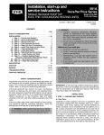
CONTROLLER
EconoMi$er IV (2 to 12--1/2 Ton Units)
See Fig. 1 for EconoMi$er IV component locations. To
install the vertical EconoMi$er IV, perform the following
procedure:
1. Turn off unit power supply and install lockout tag.
!
WARNING
CRECOMZR
DESCRIPTION
2 ---6 Ton Power Exhaust 208 ---230 v 1 Ph
2 ---6 Ton Power Exhaust 460 v 3 Ph
71/2 ---121/2 Ton Power Exhaust 208 ---230 v 1 Ph
71/2 ---121/2 Ton Power Exhaust 460 v 3 Ph
13 ---25 Ton Power Exhaust (208/230, 460 v)
13 ---25 Ton Power Exhaust (575 v)
13 ---25 Ton Power Exhaust (220, 400 v --- 50 Hz)
Barometric Relief Package (13 to 25 Tons)
Return Air Temperature Sensor
Outdoor Air Enthalpy Sensor
Indoor Air Enthalpy Sensor
Return Air CO2 Sensor (4 to 20 mA)
WIRING
HARNESS
ACTUATOR
(HIDDEN)
LOW TEMPERATURE
COMPRESSOR
LOCKOUT SWITCH
OUTSIDE AIR
TEMPERATURE SENSOR
(OPERATING LOCATION)
ELECTRICAL SHOCK HAZARD
Failure to follow this warning could result in personal
injury and/or death.
Disconnect power supply and install lockout tag
before attempting to install accessory.
C07367
Fig. 1 - EconoMi$er IV Component Locations —
2 to 12-- 1/2 Ton Units (2 to 6 Ton Shown)
FILTER ACCESS PANEL
2. Remove the existing unit filter access panel. Raise
the panel and swing the bottom outward. The panel
is now disengaged from the track and can be
removed. (See Fig. 2.)
3. Remove the indoor coil access panel and discard.
(See Fig 2.)
4. The EconoMi$er IV hood components are shipped
with the EconoMi$er IV. Remove hood from
packaging. The hood top and sides are shipped
factory assembled. Hood sides are shipped attached
to the divider panel with a screw. Remove screw
and separate panels.
COMPRESSOR
ACCESS PANEL
OUTDOOR-AIR OPENING AND
INDOOR COIL ACCESS PANEL
C06023
Fig. 2 - Typical Outdoor-- Air Section Access Panel
Locations (2 to 12-- 1/2 Ton Units)
IMPORTANT: If the power exhaust accessory is to be
installed on the unit, the hood shipped with the unit will
not be used and may be discarded. Save the aluminum
filter for use in the power exhaust hood assembly.
5. Insert the hood divider between the hood sides. (See
Fig. 3.) Secure hood divider with 2 screws
(provided) on each hood side. Screws should go
through the hood sides into the divider. The hood
divider is also used as the bottom filter rack for the
aluminum filter.
3
CRECOMZR
6. Open the filter clips which are located underneath
the hood top. Insert the aluminum filter into the
bottom filter rack (hood divider). Push the filter into
position past the open filter clips. Close the filter
clips to lock the filter into place. (See Fig. 4.)
7. Slide the EconoMi$er IV assembly into the rooftop
unit. (See Fig. 5.) Remove the shipping tape holding
the EconoMi$er IV barometric relief dampers in
place. Be sure to engage the rear EconoMi$er IV
flange under the tabs in the return-- air opening of
the unit base. (See Fig. 6.)
8. Secure the EconoMi$er IV to unit along side and
bottom flanges using the screws provided.
9. Remove and save the 12-- pin jumper plug from the
unit wiring harness (located in the upper left corner
of the unit). Insert the EconoMi$er IV plug into the
unit wiring harness. See Fig. 7 for wiring diagram.
HOOD TOP
OUTSIDE
AIR
HOOD
DIVIDER
CLEANABLE
ALUMINUM
FILTER
BAROMETRIC
AIRFLOW
C07369
Fig. 4 - Filter Installation (2 to 12-- 1/2 Ton Units)
11. Remove the indoor-- fan motor access panel. (See
Fig. 8.)
12. The supply air temperature sensor looks like an
eyelet terminal with wires running to it. The sensor
is located on the “crimp end” and is sealed from
moisture.
Mount the supply air temperature sensor (provided)
to the lower left section of the indoor fan blower
housing. (See Fig. 9.) Use the screw provided and
use the existing hole in the blower housing. Connect
the violet and pink wires to the corresponding
connections on the supply air temperature sensor.
(See Fig. 7.)
NOTE: The 12-- pin jumper plug should be saved for
future use in the event that the EconoMi$er IV is removed
from the unit. The jumper plug is not needed as long as
the EconoMi$er IV is installed.
10. The OAT sensor is taped to the economizer divider
plate for shipping. Remove tape and relocate to the
upper LH front economizer plate as shown in Fig. 1.
The OA temperature sensor will mount over the
label installed in this location. Secure the sensor
with the two screws provided.
A
FILTER CLIP
B
HOOD TOP
AND SIDE
ASSEMBLY
C
D
HOOD
DIVIDER
C07370
ECONOMIZER P/N
CRECOMZR020A02
CRECOMZR021A03
A
33.37”
40.37”
B
17.43”
22.28”
C
19.05”
24.48”
D
29.5”
36.27”
Fig. 5 - EconoMi$er IV Installed in HVAC Unit
(2 to 6 Ton Shown)
SHIP WT.
55 lb
80 lb
C07368
Fig. 3 - Hood Assembly (2 to 12-- 1/2 Ton Units)
4
ECONOMISER IV
HOLD DOWN
TAB
ECONOMISER IV
UNIT BASE
ECONOMISER IV REAR FLANGE
C07371
Fig. 6 - Rear EconoMi$er IV Flange Installation
(2 to 12-- 1/2 Ton Units)
13. Replace the indoor fan motor access panel.
14. Install the EconoMi$er IV hood over the
EconoMi$er IV. Use screws provided. (See Fig. 10.)
FOR OCCUPANCY CONTROL
REPLACE JUMPER WITH
FIELD-SUPPLIED TIME CLOCK
8
LEGEND
DCV — Demand Controlled Ventilation
IAQ — Indoor Air Quality
LALS — Low Temperature Compressor
Lockout Switch
OAT — Outdoor-Air Temperature
POT — Potentiometer
RAT — Return-Air Temperature
Potentiometer Defaults Settings:
Power Exhaust Middle
Minimum Pos.
Fully Closed
DCV Max.
Middle
DCV Set
Middle
Enthalpy
C Setting
NOTES:
1. 620 ohm, 1 watt 5% resistor should be removed only when using differential
enthalpy or dry bulb.
2. If a separate field-supplied 24 v transformer is used for the IAQ sensor power
supply, it cannot have the secondary of the transformer grounded.
3. For field-installed remote minimum position POT, remove black wire jumper
between P and P1 and set control minimum position POT to the minimum
position.
- - - - — Field Supplied Wiring
Fig. 7 - EconoMi$er IV Wiring (2 to 12-- 1/2 Ton Units)
5
C07462
CRECOMZR
15. Review the controller setting options in the
Operation section.
a. The standard EconoMi$er IV controller has a
factory setting of “C” for the outdoor air
temperature changeover and 55_F for the supply
air temperature sensor. The outdoor air
temperature settings can be adjusted at the
EconoMi$er IV controller.
b. The low temperature compressor lockout switch
setting is fixed at 42_F.
c. The minimum position for the outdoor damper
can be configured at the controller.
d. Settings for the optional return air temperature
sensor, outdoor enthalpy sensor, indoor enthalpy
sensor, and CO2 sensor can also be configured at
the controller.
16. Replace the filter access panel. Slide top of panel
into track and lift. Push bottom of panel into place.
17. Install all EconoMi$er IV accessories.
UNIT FILTER
RACK
EconoMi$er IV (13 to 25 Ton Units)
CENTER POST
!
THERMOSTAT
CONNECTION
ACCESS PANEL
ELECTRICAL SHOCK HAZARD
Failure to follow this warning could result in personal
injury and/or death.
Disconnect power supply and install lockout tag.
HEATING ACCESS
PANEL
INDOOR FAN MOTOR
ACCESS PANEL
C07372
Fig. 8 - Typical Indoor Fan Motor Access Panel
Locations (2 to 25 Ton Units)
CRECOMZR
WARNING
SUPPLY AIR
TEMPERATURE
SENSOR
MOUNTING
LOCATION
SUPPLY AIR
TEMPERATURE
SENSOR
TO UNIT
CONTROL BOX
Fig. 9 - Supply Air Sensor Placement
(2 to 12-- 1/2 Ton Units)
C07373
ECONOMISER IV
Install EconoMi$er IV damper assembly as follows:
1. If base unit is installed and in operation, turn off all
power to unit.
2. Remove filter access panel. Remove economizer
hood. (See Fig. 11.)
3. Remove 25% outdoor air damper section. Save
screws. (See Fig. 12.)
4. Remove shorting plug located in the left front of
return air compartment at back of unit control box.
(See Fig. 12.)
5. Remove EconoMi$er IV damper assembly from
shipping carton. (See Fig. 13.)
6. Install seal strip on left and right sides of
EconoMi$er IV opening.
7. Slide EconoMi$er IV assembly into unit opening as
shown in Fig. 14. Fig. 15 shows the EconoMi$er IV
installed in the unit.
8. Secure bottom of assembly to unit. For end view of
installed EconoMi$er IV, see Fig. 16. Ensure that
EconoMi$er IV bottom flange is positioned on
basepan before installing 2 screws connecting
bottom flange to unit basepan.
ECONOMISER IV
HOOD
UNIT TOP
STANDARD
25% AIR/ECONOMI$ER IV COVER
HOOD
OUTDOOR
AIR FANS
MOUNTING
SCREWS
Fig. 10 - EconoMi$er IV Hood Installation
(2 to 12-- 1/2 Ton Units)
C07374
FILTER ACCESS PANEL
C07375
Fig. 11 - Base Unit Details (13 to 25 Ton Units)
6
SCREWS ECONOMI$ERIV
OUTDOOR AIR
TEMPERATURE SENSOR
FRAME
(INSTALLED OPERATION
SCREWS
TOP
POSITION)
LOW TEMPERATURE
COMPRESSOR
LOCKOUT SWITCH
C07246
Fig. 12 - Standard 25% Outdoor-- Air Section Details
(13 to 25 Ton Units)
C07376
CRECOMZR
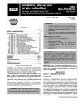
Fig. 15 - EconoMi$er IV Assembled in Unit —
End View (13 to 25 Ton Units)
SUPPLY AIR
TEMPERATURE SENSOR
LOCATION
ECONOMI$ERIV
ACTUATOR
TR1
TR
Vac
24
COM
24
Vac
HOT
EXH
Set
_
+
2
10V
N1
CONTROLLER
2V
1
N
4
n
P
T1
5
Min
Pos
EXH
P1
Ope
3
DCV
Max
T
EF1
10V
EF
2V
DCV
Set
DCV
10V
AQ1
AQ
2V
SO+
C
Free l
Coo B
SO
SR+
SR
D
A
FLANGE
AND SCREWS
(HIDDEN)
C07377
Fig. 16 - EconoMi$er IV Assembled in Unit — Side
View (13 to 25 Ton Units)
C07247
Fig. 13 - EconoMi$er IV Shipping Packaging
(13 to 25 Ton Units)
9. Using 4 screws removed at Step 3, secure the
damper assembly to the unit. (See Fig. 15.)
10. Plug EconoMi$er IV wiring assembly into the
receptacle at the back of unit control box where
shorting plug was removed. (See Fig. 17.) See Fig.
18 for wiring diagram.
11. Install frame top above damper assembly. (See Fig.
15.)
12. Install supply air temperature sensor in fan section
on hole provided on fan housing. (See Fig. 16.)
Route wiring to EconoMi$er IV controller through
knockout hole in panel. Use bushing provided. Use
wire tie to keep wiring away from fan blades.
13. Relocate outdoor air temperature sensor from
shipping position to operation position on
EconoMi$er IV. (See Fig. 15.)
C07248
Fig. 14 - Slide EconoMi$er IV Assembly Into Unit
(13 to 25 Ton Units)
7
IMPORTANT: Failure to relocate the sensor will result in
the EconoMi$er IV not operating properly.
14. Re-- install economizer hood. Refer to base unit
installation instructions. (See Fig. 19.)
CRECOMZR
ECONOMI$ER IV
PLUG
CONFIGURATION
EconoMi$er IV Standard Sensors
Outdoor Air Temperature (OAT) Sensor
The outdoor air temperature sensor (HH57AC074) is a 10
to 20 mA device used to measure the outdoor-- air
temperature. The outdoor-- air temperature is used to
determine when the EconoMi$er IV can be used for free
cooling. The sensor is factory-- installed on the
EconoMi$er IV in the outdoor airstream on 2 to 121/2 ton
units and must be relocated on 13 to 25 ton units. (See
Fig. 1 and 15.) The operating range of temperature
measurement is 40_ to 100_F.
WIRE TIE
C07378
Fig. 17 - EconoMi$er IV Plug (13 to 25 Ton Units)
LEGEND
DCV — Demand Controlled Ventilation
IAQ — Indoor Air Quality
LALS — Low Temperature Compressor
Lockout Switch
OAT — Outdoor-Air Temperature
POT — Potentiometer
Potentiometer Defaults Settings:
Power Exhaust Middle
Minimum Pos.
Fully Closed
DCV Max.
Middle
DCV Set
Middle
Enthalpy
C Setting
NOTES:
1. 620 ohm, 1 watt 5% resistor should be removed only when using differential
enthalpy or dry bulb.
2. If a separate field-supplied 24 v transformer is used for the IAQ sensor power
supply, it cannot have the secondary of the transformer grounded.
3. For field-installed remote minimum position POT, remove black wire jumper
between P and P1 and set control minimum position POT to the minimum
position.
Fig. 18 - EconoMi$er IV Wiring (13 to 25 Ton Units)
8
C07379
Fig. 19 - Outdoor-- Air Hood Details
(13 to 25 Ton Units)
TEMPERATURE (F)
---58
---40
---22
---4
14
32
50
68
77
86
104
122
140
158
176
185
194
212
230
248
257
266
284
302
C07380
Supply Air Temperature (SAT) Sensor
The supply air temperature sensor is a 3 K thermistor
located at the inlet of the indoor fan. (See Fig. 9 and 16.)
This sensor is field installed. The operating range of
temperature measurement is 0° to 158°F. See Table 3 for
sensor temperature/resistance values.
The temperature sensor looks like an eyelet terminal with
wires running to it. The sensor is located in the “crimp
end” and is sealed from moisture.
Low Temperature Compressor Lockout Switch
The EconoMi$er IV is equipped with a low ambient
temperature lockout switch located in the outdoor
airstream which is used to lock out the compressors below
a 42°F ambient temperature. (See Fig. 1 and 15.)
EconoMi$er IV Control Modes
Determine the EconoMi$er IV control mode before set up
of the control. Some modes of operation may require
different sensors. Refer to Table 1. The EconoMi$er IV is
supplied from the factory with a supply air temperature
sensor, a low temperature compressor lockout switch, and
an outdoor air temperature sensor. This allows for
operation of the EconoMi$er IV with outdoor air dry bulb
changeover control. Additional accessories can be added
to allow for different types of changeover control and
operation of the EconoMi$er IV and unit.
When using differential enthalpy or differential
temperature control strategies and “integrated economizer
operation” is desired, a 2-- stage cooling thermostat is
required even on 1-- stage cooling units (2-- 6 ton rooftop
units). A thermostat lead must be made between
Y2-- output on thermostat and Y2-- input on rooftop unit’s
Low Voltage Terminal Board (LVTB). Internal wiring
between Y2-- input on the unit LVTB and the economizer
controller’s Y2 input already exists in unit wiring harness
and the economizer plug, so no field modifications are
required.
RESISTANCE (ohms)
200,250
100,680
53,010
29,091
16,590
9,795
5,970
3,747
3,000
2,416
1,597
1,080
746
525
376
321
274
203
153
116
102
89
70
55
Outdoor Dry Bulb Changeover
The standard controller is shipped from the factory
configured for outdoor dry bulb changeover control. The
outdoor air and supply air temperature sensors are
included as standard. For this control mode, the outdoor
temperature is compared to an adjustable set point
selected on the control. If the outdoor-- air temperature is
above the set point, the EconoMi$er IV will adjust the
outdoor air dampers to minimum position. If the
outdoor-- air temperature is below the set point, the
position of the outdoor-- air dampers will be controlled to
provide free cooling using outdoor air. When in this mode,
the LED next to the free cooling set point potentiometer
will be on. The changeover temperature set point is
controlled by the free cooling set point potentiometer
located on the control. (See Fig. 20.) The scale on the
potentiometer is A, B, C, and D. See Fig. 21 for the
corresponding temperature changeover values.
9
CRECOMZR
Table 3 – Supply Air Sensor Temperature/Resistance
Values
Differential Enthalpy Control
For differential dry bulb control the standard outdoor dry
bulb sensor is used in conjunction with an additional
accessory
return
air
sensor
(part
number
CRTEMPSN002A00). The accessory sensor must be
mounted in the return airstream. (See Fig. 22 and 23.)
(See Fig. 7 and 18.)
In this mode of operation, the outdoor-- air temperature is
compared to the return-- air temperature and the lower
temperature airstream is used for cooling. When using this
mode of changeover control, turn the free
cooling/enthalpy set point potentiometer fully clockwise
to the D setting. (See Fig. 20.)
For differential enthalpy control, the EconoMi$er IV
controller uses two enthalpy sensors (HH57AC078 and
CRENTDIF004A00), one in the outside air and one in the
return airstream. The EconoMi$er IV controller compares
the outdoor air enthalpy to the return air enthalpy to
determine EconoMi$er IV use. The controller selects the
lower enthalpy air (return or outdoor) for cooling. For
example, when the outdoor air has a lower enthalpy than
the return air and is below the set point, the EconoMi$er
IV opens to bring in outdoor air for free cooling.
Replace the standard outside air dry bulb temperature
sensor with the accessory enthalpy sensor in the same
mounting location. See Fig. 1 and 15. Mount the return air
enthalpy sensor in the return air duct (2 to 121/2 ton units)
or on the EconoMi$er IV (13 to 25 ton units). (See Fig. 22
and 23.) (See Fig. 7 and 18.) When using this mode of
changeover control, turn the enthalpy set point
potentiometer fully clockwise to the D setting.
CRECOMZR
Differential Dry Bulb Control
Indoor Air Quality (IAQ) Sensor Input
The IAQ input can be used for demand control ventilation
control based on the level of CO2 measured in the space
or return air duct.
Mount the accessory IAQ sensor according to
manufacturer specifications. The IAQ sensor should be
wired to the AQ and AQ1 terminals of the controller.
Adjust the DCV potentiometers to correspond to the DCV
voltage output of the indoor air quality sensor at the
user-- determined set point. (See Fig. 24.)
C07385
Fig. 20 - EconoMi$er IV Controller Potentiometer
and LED Locations
CAUTION
!
EQUIPMENT DAMAGE HAZARD
Failure to follow this caution may result in damage to
equipment.
If a separate field-- supplied transformer is used to
power the IAQ sensor, the sensor must not be
grounded or the EconoMi$er IV control board will be
damaged.
Outdoor Enthalpy Changeover
For enthalpy control, accessory enthalpy sensor (part
number HH57AC078) is required. Replace the standard
outdoor dry bulb temperature sensor with the accessory
enthalpy sensor in the same mounting location. (See Fig. 1
and 15.) When the outdoor air enthalpy rises above the
outdoor enthalpy changeover set point, the outdoor-- air
damper moves to its minimum position. The outdoor
enthalpy changeover set point is set with the outdoor
enthalpy set point potentiometer on the EconoMi$er IV
controller. The set points are A, B, C, and D. (See Fig.
25.) The factory-- installed 620-- ohm jumper must be in
place across terminals SR and SR+ on the EconoMi$er IV
controller. (See Fig. 26.)
19
LED ON
18
D
17
LED OFF
16
mA
15
14
LED ON
C
LED OFF
13
12
LED ON
B
LED OFF
LED ON
A
11
10
LED OFF
9
40
45
50
55
60
65 70 75 80
DEGREES FAHRENHEIT
85
90
95
100
C06035
Fig. 21 - Outdoor Air Temperature Changeover
Set Points
10
ECONOMI$ERIV
CONTROLLER
ECONOMI$ERIV
GROMMET
RETURN AIR
SENSOR
TR
1
TR
Vac
24 M
CO
Se
24
Vac T
HO
t
_
+
10V
N1
2
2V
N
EX
P1
1
H
5
Min s
Po
P
T1
Op
4
en
DC
V
Ma
T
3
x
EF
10V
DC
DC
V
1
EF
2V
AQ
There is a minimum damper position potentiometer on the
EconoMi$er IV controller. (See Fig. 20.) The minimum
damper position maintains the minimum airflow into the
building during the occupied period.
When using demand ventilation, the minimum damper
position represents the minimum ventilation position for
VOC
(volatile
organic
compound)
ventilation
requirements. The maximum demand ventilation position
is used for fully occupied ventilation.
When demand ventilation control is not being used, the
minimum position potentiometer should be used to set the
occupied ventilation position. The maximum demand
ventilation position should be turned fully clockwise.
Adjust the minimum position potentiometer to allow the
minimum amount of outdoor air, as required by local
codes, to enter the building. Make minimum position
adjustments with at least 10_F temperature difference
between the outdoor and return-- air temperatures.
1
V
Se
t
10V
AQ
SO
2V
+
e
Fre ol
Co
SO
+
SR
SR
C
B
D
CO2 SENSOR MAX RANGE SETTING
A
IAQ
SENSOR
RETURN AIR
SENSOR
C07386
Fig. 23 - Return Air Temperature or Enthalpy Sensor
Mounting Location (13 to 25 Tons)
RANGE CONFIGURATION (ppm)
6000
5000
4000
800 ppm
900 ppm
1000 ppm
1100 ppm
3000
2000
1000
0
2
3
4
5
6
7
8
DAMPER VOLTAGE FOR MAX VENTILATION RATE
C06039
Fig. 24 - CO2 Sensor Maximum Range Setting
11
CRECOMZR
C07085
Fig. 22 - Return Air Temperature or Enthalpy Sensor
Mounting Location (2 to 12-- 1/2 Ton Units)
H
The exhaust set point will determine when the exhaust fan
runs based on damper position (if accessory power
exhaust is installed). The set point is modified with the
Exhaust Fan Set Point (EXH SET) potentiometer. (See
Fig. 20.) The set point represents the damper position
above which the exhaust fans will be turned on. When
there is a call for exhaust, the EconoMi$er IV controller
provides a 45-- 15 second delay before exhaust fan
activation to allow the dampers to open. This delay allows
the damper to reach the appropriate position to avoid
unnecessary fan overload.
Minimum Position Control
RETURN DUCT
(FIELD-PROVIDED)
EX
Exhaust Set Point Adjustment
46
85
90
95 100 105 110
(29) (32) (35) (38) (41) (43)
44
CONTROL CONTROL POINT
CURVE
APPROX. deg. F (deg. C)
HU
MID
ITY
38
AT
32
IVE
34
75
(24)
EN
TH
A
2 8 LP
Y
BT
U
PE
R
PO
UN
36 D D
RY
(%
)
40
AI
R
73 (23)
70 (21)
67 (19)
63 (17)
RE
L
80
22
60
70
24
10
0
90
26
30
70
(21)
65
(18)
20
50
60
(16)
40
A
16
14
50
(10)
45
(7)
30
18
55
(13) B
12
CRECOMZR
80
(27)
42
AT 50% RH
A
B
C
D
C
20
D
40
(4)
10
35
(2)
B A
D C
35
(2)
40
(4)
45
(7)
50
(10)
HIGH LIMIT
CURVE
55
60
70
65
75
80
85
90
95 100 105 110
(13) (16) (18) (21) (24) (27) (29) (32) (35) (38) (41) (43)
APPROXIMATE DRY BULB TEMPERATURE--degrees F (degrees C)
C06037
Fig. 25 - Enthalpy Changeover Set Points
EXH
N1
N
P
Min
Pos
T1
DCV
2V
SO+
SR+
SR
24 Vac
COM
+
_
Max
10V
1
2
5
DCV
AQ
SO
24
Vac
HOT
Open
T
AQ1
TR1
Set
10V
2V
EXH
P1
TR
2V
DCV
Set
10V
Free
Cool
B
C
A
D
3
4
EF
EF1
Fig. 26 - EconoMi$er IV Controller
12
C06038
Remote control of the EconoMi$er IV damper is desirable
when requiring additional temporary ventilation. If a
field-- supplied remote potentiometer (Honeywell part
number S963B1128) is wired to the EconoMi$er IV
controller, the minimum position of the damper can be
controlled from a remote location.
To control the minimum damper position remotely,
remove the factory-- installed jumper on the P and P1
terminals on the EconoMi$er IV controller. Wire the
field-- supplied potentiometer to the P and P1 terminals on
the EconoMi$er IV controller. (See Fig. 26.)
Damper Movement
Damper movement from full open to full closed (or vice
versa) takes 21/2 minutes.
Thermostats
The EconoMi$er IV control works with conventional
thermostats that have a Y1 (cool stage 1), Y2 (cool stage
2), W1 (heat stage 1), W2 (heat stage 2), and G (fan). The
EconoMi$er IV control does not support space
temperature sensors. Connections are made at the
thermostat terminal connection board located in the main
control box.
Occupancy Control
The factory default configuration for the EconoMi$er IV
control is occupied mode. Occupied status is provided by
the black jumper from terminal TR to terminal N. When
unoccupied mode is desired, install a field-- supplied
timeclock function in place of the jumper between TR and
N. (See Fig. 7 and 18.) When the timeclock contacts are
closed, the EconoMi$er IV control will be in occupied
mode. When the timeclock contacts are open (removing
the 24-- v signal from terminal N), the EconoMi$er IV will
be in unoccupied mode.
NOTE: On 48/50TC models, do NOT cut the occupancy
jumper on terminal board.
Demand Controlled Ventilation (DCV)
When using the EconoMi$er IV for demand controlled
ventilation, there are some equipment selection criteria
which should be considered. When selecting the heat
capacity and cool capacity of the equipment, the
maximum ventilation rate must be evaluated for design
conditions. The maximum damper position must be
calculated to provide the desired fresh air.
Typically the maximum ventilation rate will be about 5 to
10% more than the typical cfm required per person, using
normal outside air design criteria.
An exponential anticipatory strategy should be taken with
the following conditions: a zone with a large area, varied
occupancy, and equipment that cannot exceed the required
ventilation rate at design conditions. Exceeding the
required ventilation rate means the equipment can
condition air at a maximum ventilation rate that is greater
than the required ventilation rate for maximum
occupancy. An exponential-- anticipatory strategy will
cause the fresh air supplied to increase as the room CO2
level increases even though the CO2 set point has not been
reached. By the time the CO2 level reaches the set point,
the damper will be at maximum ventilation and should
maintain the set point.
In order to have the CO2 sensor control the economizer
damper in this manner, first determine the damper voltage
output for minimum or base ventilation. Base ventilation
is the ventilation required to remove contaminants during
unoccupied periods. The following equation may be used
to determine the percent of outside-- air entering the
building for a given damper position. For best results there
should be at least a 10 degree difference in outside and
return-- air temperatures.
(T O × OA) + (TR × RA ) = TM
100
100
TO = Outdoor-- Air Temperature
OA = Percent of Outdoor Air
TR = Return-- Air Temperature
RA = Percent of Return Air
TM = Mixed-- Air Temperature
Once base ventilation has been determined, set the
minimum damper position potentiometer to the correct
position.
13
CRECOMZR
To determine the minimum position setting, perform the
following procedure:
1. Calculate the appropriate mixed air temperature
using the following formula:
T O × OA + (TR × RA ) = TM
100
100
TO = Outdoor-- Air Temperature
OA = Percent of Outdoor Air
TR = Return-- Air Temperature
RA = Percent of Return Air
TM = Mixed-- Air Temperature
As and example, if local codes require 10% outdoor
air during occupied conditions, outdoor-- air
temperature is 60_F, and return-- air temperature is
75_F.
(60 x .10) + (75 x .90) = 73.5_F
2. Disconnect the supply air sensor from terminals T
and T1.
3. Ensure that the factory-- installed jumper is in place
across terminals P and P1. If remote damper
positioning is being used, make sure that the
terminals are wired according to Fig. 7 and 18 and
that the minimum position potentiometer is turned
fully clockwise.
4. Connect 24 vac across terminals TR and TR1.
5. Carefully
adjust
the
minimum
position
potentiometer until the measured mixed-- air
temperature matches the calculated value.
6. Reconnect the supply air sensor to terminals T and
T1.
CRECOMZR
The same equation can be used to determine the occupied
or maximum ventilation rate to the building. For example,
an output of 3.6 volts to the actuator provides a base
ventilation rate of 5% and an output of 6.7 volts provides
the maximum ventilation rate of 20% (or base plus 15 cfm
per person). Use Fig. 24 to determine the maximum
setting of the CO2 sensor. For example, a 1100 ppm set
point relates to a 15 cfm per person design. Use the 1100
ppm curve on Fig. 24 to find the point when the CO2
sensor output will be 6.7 volts. Line up the point on the
graph with the left side of the chart to determine that the
range configuration for the CO2 sensor should be 1800
ppm. The EconoMi$er IV controller will output the 6.7
volts from the CO2 sensor to the actuator when the CO2
concentration in the space is at 1100 ppm. The DCV set
point may be left at 2 volts since the CO2 sensor voltage
will be ignored by the EconoMi$er IV controller until it
rises above the 3.6 volt setting of the minimum position
potentiometer.
Once the fully occupied damper position has been
determined, set the maximum damper demand control
ventilation potentiometer to this position. Do not set to the
maximum position as this can result in over-- ventilation to
the space and potential high-- humidity levels.
CO2 Sensor Configuration
The CO2 sensor has preset standard voltage settings that
can be selected anytime after the sensor is powered up.
(See Table 4.)
Use setting 1 or 2 for Carrier/Bryant equipment. (See
Table 4.)
1. Press Clear and Mode buttons. Hold at least 5
seconds until the sensor enters the Edit mode.
2. Press Mode twice. The STDSET Menu will appear.
3. Use the Up/Down button to select the preset
number. (See Table 6.)
4. Press Enter to lock in the selection.
5. Press Mode to exit and resume normal operation.
The custom settings of the CO2 sensor can be changed
anytime after the sensor is energized. Follow the steps
below to change the non-- standard settings:
1. Press Clear and Mode buttons. Hold at least 5
seconds until the sensor enters the Edit mode.
2. Press Mode twice. The STDSET Menu will appear.
3. Use the Up/Down button to toggle to the NONSTD
menu and press Enter.
4. Use the Up/Down button to toggle through each of
the nine variables, starting with Altitude, until the
desired setting is reached.
5. Press Mode to move through the variables.
6. Press Enter to lock in the selection, then press Mode
to continue to the next variable.
Dehumidification of Fresh Air with DCV Control
Information from ASHRAE indicates that the largest
humidity load on any zone is the fresh air introduced. For
some applications, an energy recovery unit can be added
to reduce the moisture content of the fresh air being
brought into the building when the enthalpy is high. In
most cases, the normal heating and cooling processes are
more than adequate to remove the humidity loads for most
commercial applications.
If normal rooftop heating and cooling operation is not
adequate for the outdoor humidity level, an energy
recovery unit and/or a dehumidification option should be
considered.
Table 4 – CO2 Sensor Standard Settings
OUTPUT
VENTILATION
RATE
(cfm/Person)
ANALOG
OUTPUT
OPTIONAL
RELAY
SETPOINT (ppm)
RELAY
HYSTERESIS
(ppm)
Proportional
Any
0--- 10V
4--- 20 mA
0---2000
1000
50
Any
2--- 10V
4--- 20 mA
Proportional
0---2000
1000
50
3
Exponential
Any
0--- 10V
4--- 20 mA
0---2000
1100
50
4
Proportional
15
0--- 10V
4--- 20 mA
0---1100
1100
50
5
Proportional
20
0--- 10V
4--- 20 mA
0--- 900
900
50
Exponential
15
0--- 10V
4--- 20 mA
0---1100
1100
50
Exponential
20
0--- 10V
4--- 20 mA
0--- 900
900
50
SETTING
EQUIPMENT
1
2
6
Interface w/Standard
Building Control
System
Economizer
7
CO2 CONTROL
RANGE (ppm)
8
Health & Safety
Proportional
—
0--- 10V
4--- 20 mA
0---9999
5000
500
9
Parking/Air
Intakes/Loading
Docks
Proportional
—
0--- 10V
4--- 20 mA
0---2000
700
50
LEGEND
ppm — Parts Per Million
14
OPERATION
Table 5 – CO2 Sensor Standard Settings
Sequence of Operation
LEAKAGE
(cfm)
35
53
65
75
90
102
Table 6 – Return Air Pressure Drop (in. wg)
(13 to 25 Ton Units)
CFM
4500 5000 5400 6000 7200 7500 7500
0.040 0.050 0.060 0.070 0.090 0.100 0.110
10,000
0.120
11,250
0.140
2000
1500
3 -6 Ton
7½ - 12½ Ton
1000
500
0
0
0.05
0.1
0.15
0.2
0.25
0.3
RETURN DUCT STATIC PRESSURE (in. wg)
Fig. 27 - Barometric Relief Flow Capacity
(2 to 12-- 1/2 Ton Units)
C08326
LEAKAGE ACROSS DAMPER (CFM)
30
25
20
3 - 6 Ton
7 1/2 - 12 1/2 Ton
15
10
5
0
0.00
0.10
0.20
0.30
0.40
0.50
STATIC PRESSURE DELTA (in. wg)
Fig. 28 - Outdoor Air Damper Leakage
(2 to 12-- 1/2 Ton Units)
Performance Data
C08327
6000
5000
4000
3 - 6 TON
7 1/2 - 12 1/2 Ton
3000
2000
1000
0
0
Refer to Fig. 27 for barometric relief capacity. Refer to
Fig. 28 and Table 5 for outdoor air leakage. Refer to Fig.
29 and Table 6 for return air pressure drop.
0.1
0.2
0.3
0.4
RETURN DUCT STATIC PRESSURE DROP (in. wg)
Fig. 29 - Return Air Pressure Drop
(2 to 12-- 1/2 Ton Units)
15
C08328
CRECOMZR
RELIEF FLOW (CFM)
2500
RETURN AIR FLOW (CFM)
When free cooling is not available, the compressors will
be controlled by the zone thermostat. When free cooling is
available, the outdoor-- air damper is modulated by the
EconoMi$er IV control to provide a 50_ to 55_F
supply-- air temperature into the zone. As the supply-- air
temperature fluctuates above 55_ or below 50_F, the
dampers will be modulated (open or close) to bring the
supply-- air temperature back within the set points.
For EconoMi$er IV operation, there must be a thermostat
call for the fan (G). This will move the damper to its
minimum position during the occupied mode.
Above 50_F supply-- air temperature, the dampers will
modulate from 100% open to the minimum open position.
From 50_F to 45_F supply-- air temperature, the dampers
will maintain at the minimum open position. Below 45_F
supply air temperature, the dampers will be completely
shut. As the supply-- air temperature rises, the dampers will
come back open to the minimum open position once the
supply-- air temperature rises to 48_F.
If optional power exhaust is installed, as the outdoor-- air
damper opens and closes, the power exhaust fans will be
energized and de-- energized.
If field-- installed accessory CO2 sensors are connected to
the EconoMi$er IV control, a demand controlled
ventilation strategy will begin to operate. As the CO2
level in the zone increases above the CO2 set point, the
minimum position of the damper will be increased
proportionally. As the CO2 level decreases because of the
increase in fresh air, the outdoor-- air damper will be
proportionally closed. Damper position will follow the
higher demand condition from DCV mode or free cooling
mode.
Damper movement from full closed to full open (or vice
versa) will take between 1-- 1/2 and 2-- 1/2 minutes.
If free cooling can be used as determined from the
appropriate changeover command (switch, dry bulb,
enthalpy curve, differential dry bulb, or differential
enthalpy), a call for cooling (Y1 closes at the thermostat)
will cause the control to modulate the dampers open to
maintain the supply air temperature set point at 50_ to
55_F.
As the supply air temperature drops below the set point
range of 50_ to 55_F, the control will modulate the
outdoor-- air dampers closed to maintain the proper
supply-- air temperature.
DAMPER STATIC PRESSURE (in. wg)
0.2
0.4
0.6
0.8
1.0
1.2
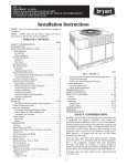
TROUBLESHOOTING
See Table 7 for EconoMi$er IV logic.
A functional view of the EconoMi$er IV is shown in Fig.
30. Typical settings, sensor ranges, and jumper positions
are also shown. An EconoMi$er IV simulator program is
available to help with EconoMi$er IV training and
troubleshooting.
EconoMi$er IV Preparation
This procedure is used to prepare the EconoMi$er IV for
troubleshooting. No troubleshooting or testing is done by
performing the following procedure.
Differential Enthalpy
To check differential enthalpy:
1. Make sure EconoMi$er IV preparation procedure
has been performed.
2. Place 620-- ohm resistor across SO and +.
3. Place 1.2 kilo-- ohm resistor across SR and +. The
Free Cool LED should be lit.
4. Remove 620-- ohm resistor across SO and +. The
Free Cool LED should turn off.
5. Return EconoMi$er IV settings and wiring to
normal after completing troubleshooting.
CRECOMZR
Single Enthalpy
NOTE: This procedure requires a 9-- v battery, 1.2
kilo-- ohm resistor, and a 5.6 kilo-- ohm resistor which are
not supplied with the EconoMi$er IV.
IMPORTANT: Be sure to record the positions of all
potentiometers before starting troubleshooting.
1. Disconnect power at TR and TR1. All LEDs should
be off. Exhaust fan contacts should be open.
2. Disconnect device at P and P1.
3. Jumper P to P1.
4. Disconnect wires at T and T1. Place 5.6 kilo-- ohm
resistor across T and T1.
5. Jumper TR to 1.
6. Jumper TR to N.
7. If connected, remove sensor from terminals SO and
+. Connect 1.2 kilo-- ohm 4074EJM checkout
resistor across terminals SO and +.
8. Put 620-- ohm resistor across terminals SR and +.
9. Set minimum position, DCV set point, and exhaust
potentiometers fully CCW (counterclockwise).
10. Set DCV maximum position potentiometer fully
CW (clockwise).
11. Set enthalpy potentiometer to D.
12. Apply power (24 vac) to terminals TR and TR1.
To check single enthalpy:
1. Make sure EconoMi$er IV preparation procedure
has been performed.
2. Set the enthalpy potentiometer to A (fully CCW).
The Free Cool LED should be lit.
3. Set the enthalpy potentiometer to D (fully CW). The
Free Cool LED should turn off.
4. Return EconoMi$er IV settings and wiring to
normal after completing troubleshooting.
DCV (Demand Controlled Ventilation) and
Power Exhaust
To check DCV and Power Exhaust:
1. Make sure EconoMi$er IV preparation procedure
has been performed.
2. Ensure terminals AQ and AQ1 are open. The LED
for both DCV and Exhaust should be off. The
actuator should be fully closed.
3. Connect a 9-- v battery to AQ (positive node) and
AQ1 (negative node). The LED for both DCV and
Exhaust should turn on. The actuator should drive to
between 90 and 95% open.
4. Turn the Exhaust potentiometer CW until the
Exhaust LED turns off. The LED should turn off
when the potentiometer is approximately 90%. The
actuator should remain in position.
5. Turn the DCV set point potentiometer CW until the
DCV LED turns off. The DCV LED should turn off
when the potentiometer is approximately 9-- v. The
actuator should drive fully closed.
6. Turn the DCV and Exhaust potentiometers CCW
until the Exhaust LED turns on. The exhaust
contacts will close 30 to 120 seconds after the
Exhaust LED turns on.
7. Return EconoMi$er IV settings and wiring to
normal after completing troubleshooting.
16
EconoMi$er IV Troubleshooting Completion
To check the DCV minimum and maximum position:
1. Make sure EconoMi$er IV preparation procedure
has been performed.
2. Connect a 9-- v battery to AQ (positive node) and
AQ1 (negative node). The DCV LED should turn
on. The actuator should drive to between 90 and
95% open.
3. Turn the DCV Maximum Position potentiometer to
midpoint. The actuator should drive to between 20
and 80% open.
4. Turn the DCV Maximum Position potentiometer to
fully CCW. The actuator should drive fully closed.
5. Turn the Minimum Position potentiometer to
midpoint. The actuator should drive to between 20
and 80% open.
6. Turn the Minimum Position Potentiometer fully
CW. The actuator should drive fully open.
7. Remove the jumper from TR and N. The actuator
should drive fully closed.
8. Return EconoMi$er IV settings and wiring to
normal after completing troubleshooting.
This procedure is used to return the EconoMi$er IV to
operation. No troubleshooting or testing is done by
performing the following procedure.
1. Disconnect power at TR and TR1.
2. Set enthalpy potentiometer to previous setting.
3. Set DCV maximum position potentiometer to
previous setting.
4. Set minimum position, DCV set point, and exhaust
potentiometers to previous settings.
5. Remove 620-- ohm resistor from terminals SR and +.
6. Remove 1.2 kilo-- ohm checkout resistor from
terminals SO and +. If used, reconnect sensor from
terminals SO and +.
7. Remove jumper from TR to N.
8. Remove jumper from TR to 1.
9. Remove 5.6 kilo-- ohm resistor from T and T1.
Reconnect wires at T and T1.
10. Remove jumper from P to P1. Reconnect device at
P and P1.
11. Apply power (24 vac) to terminals TR and TR1.
Supply--Air Input
To check supply-- air input:
1. Make sure EconoMi$er IV preparation procedure
has been performed.
2. Set the Enthalpy potentiometer to A. The Free Cool
LED turns on. The actuator should drive to between
20 and 80% open.
3. Remove the 5.6 kilo-- ohm resistor and jumper T to
T1. The actuator should drive fully open.
4. Remove the jumper across T and T1. The actuator
should drive fully closed.
5. Return EconoMi$er IV settings and wiring to
normal after completing troubleshooting.
17
CRECOMZR
DCV Minimum and Maximum Position
Table 7 – EconoMi$er IV Input/Output Logic
Demand Control
Ventilation (DCV)
Below set
(DCV LED Off)
CRECOMZR
Above set
(DCV LED On)
INPUTS
Enthalpy*
Outdoor
Return
High
(Free Cooling LED
Off)
Low
Low
(Free Cooling LED
On)
High
(Free Cooling LED
Off)
Low
(Free Cooling LED
On)
High
Low
High
Compressor
Stage Stage
1
2
Y1
Y2
On
On
On
On
On
Off
On
Off
Off
Off
Off
Off
On
On
On
Off
On
Off
Off
Off
Off
Off
Off
Off
On
On
On
On
On
Off
On
Off
Off
Off
Off
Off
On
On
On
Off
On
Off
Off
Off
Off
Off
Off
Off
OUTPUTS
N Terminal{
Occupied
Unoccupied
Damper
Minimum position
Closed
Modulating**
(between min. position and full---open)
Minimum position
Modulating{{
(between min.
position and DCV
maximum)
Modulating**
(between closed
and full---open)
Closed
Modulating{{
(between closed
and DCV
maximum)
Modulating{{{
Modulating{{{
* For single enthalpy control, the module compares outdoor enthalpy to the ABCD set point.
{ Power at N terminal determines Occupied/Unoccupied setting: 24 vac (Occupied), no power (Unoccupied).
** Modulation is based on the supply--- air sensor signal.
{{ Modulation is based on the DCV signal.
*** Modulation is based on the greater of DCV and supply--- air sensor signals, between minimum position and either maximum position (DCV)
or fully open (supply--- air signal).
{{{ Modulation is based on the greater of DCV and supply--- air sensor signals, between closed and either maximum position (DCV) or fully
open (supply--- air signal).
18
CRECOMZR
Fig. 30 - EconoMi$er IV Functional View
19
C06053
CRECOMZR
Copyright 2008 Carrier Corp. D 7310 W. Morris St. D Indianapolis, IN 46231
Printed in U.S.A.
Edition Date: 8/08
Manufacturer reserves the right to change, at any time, specifications and designs without notice and without obligations.
20
Catalog No:IIK---CRECOMZR021---01
Replaces:48/50H,T--- 41SI