1
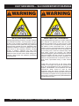
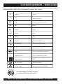
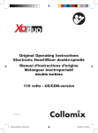
OPERATION AND PARTS MANUAL
COLLOMIX
Hand Mixers
CX100HF
CX100HFE
CX300HF
CX400HFE
CX600HF
CX600HFE
Revision #3 (03/11/08)
To find the latest revision of this
publication, visit our website at:
www.multiquip.com
THIS MANUAL MUST ACCOMPANY THE EQUIPMENT AT ALL TIMES.
CX-HF HAND MIXERS — SILICOSIS/RESPIRATORY WARNINGS
WARNING
WARNING
SILICOSIS WARNING
RESPIRATORY HAZARDS
Grinding/cutting/drilling of masonry, concrete, metal and
other materials with silica in their composition may give
off dust or mists containing crystalline silica. Silica is a
basic component of sand, quartz, brick clay, granite and
numerous other minerals and rocks. Repeated and/or
substantial inhalation of airborne crystalline silica can
cause serious or fatal respiratory diseases, including
silicosis. In addition, California and some other
authorities have listed respirable crystalline silica as a
substance known to cause cancer. When cutting such
materials, always follow the respiratory precautions
mentioned above.
Grinding/cutting/drilling of masonry, concrete, metal and
other materials can generate dust, mists and fumes
containing chemicals known to cause serious or fatal
injury or illness, such as respiratory disease, cancer,
birth defects or other reproductive harm. If you are
unfamiliar with the risks associated with the particular
process and/or material being cut or the composition of
the tool being used, review the material safety data
sheet and/or consult your employer, the material
manufacturer/supplier, governmental agencies such as
OSHA and NIOSH and other sources on hazardous
materials. California and some other authorities, for
instance, have published lists of substances known to
cause cancer, reproductive toxicity, or other harmful
effects.
Control dust, mist and fumes at the source where
possible. In this regard use good work practices and
follow the recommendations of the manufacturers or
suppliers, OSHA/NIOSH, and occupational and trade
associations. Water should be used for dust
suppression when wet cutting is feasible. When the
hazards from inhalation of dust, mists and fumes cannot
be eliminated, the operator and any bystanders should
always wear a respirator approved by NIOSH/MSHA for
the materials being used.
PAGE 2 — CX-HF SERIES HAND MIXERS — OPERATION AND PARTS MANUAL — REV. #3 (03/11/08)
CX-HF HAND MIXERS — TABLE OF CONTENTS
STOW CX-HF SERIES
HAND MIXERS
Silicosis/Respiratory Warnings .................................. 2
Table Of Contents ..................................................... 3
Parts Ordering Procedures ....................................... 4
Safety Message Alert Symbols ................................. 5
Rules For Safe Operation ...................................... 6-7
Symbols Used ........................................................... 8
Specifications ............................................................ 9
General Information ........................................... 10-11
Components............................................................ 12
Setup ....................................................................... 13
Operation ................................................................ 14
Maintenance ........................................................... 15
Explanation Of Code In Remarks Column .............. 16
Suggested Spare Parts ........................................... 17
Component Drawings
Mixer Assembly (CX100) ................................... 18-21
Mixer Assembly (CX300) ................................... 22-25
Mixer Assembly (CX400) ................................... 26-29
Mixer Assembly (CX600) ................................... 30-33
Terms and Conditions of Sale - Parts ..................... 34
NOTE
Specification and part number
are subject to change without
notice.
CX-HF SERIES MIXERS — OPERATION AND PARTS MANUAL — REV. #3 (03/11/08) — PAGE 3
CX-HF SERIES HAND MIXERS — PARTS ORDERING PROCEDURES
When ordering parts,
please supply the following information:
❒
❒
❒
❒
❒
❒
❒
Dealer account number
Dealer name and address
Shipping address (if different than billing address)
Return fax number
Applicable model number
Quantity, part number and description of each part
Specify preferred method of shipment:
✓ FedEx or UPS Ground
Note: Unless otherwise indicated by customer, all
✓ FedEx or UPS Second Day or Third Day orders are treated as “Standard Orders”, and will
ship within 24 hours. We will make every effort to
✓ FedEx or UPS Next Day
ship “Air Shipments” the same day that the order
✓ Federal Express Priority One
is received, if prior to 2PM west coast time. “Stock
✓ DHL
Orders” must be so noted on fax or web forms.
✓ Truck
Here’s how to get help...
Please have the model and serial number
on hand when calling.
STOW MAIN OFFICE
18910 Wilmington Ave.
Carson, CA 90746
Email: [email protected]
Internet: www.stowmfg.com
SALES DEPARTMENT
310-661-4242
877-289-7869 (877-BUY-STOW)
PARTS DEPARTMENT
800-427-1244
310-537-3700
SERVICE DEPARTMENT
800-478-1244
310-537-3700
TECHNICAL ASSISTANCE
800-478-1244
WARRANTY DEPARTMENT
800-421-1244, EXT. 279
310-537-3700, EXT. 279
800-421-1244
FAX: 310-537-3927
Fax: 310-604-9237
(Domestic USA Dealers Only)
Extra Discounts!
All parts orders which include complete part numbers and
are received by our automated web parts order system, or
by fax qualify for the following extra discounts:
Ordered
Standard
Stock orders
via
orders
($750 list and above)
Fax
3%
10%
Web
FAX: 800-672-7877
FAX: 310-637-3284
FAX: 310-537-4259
FAX: 310-631-5032
FAX: 310-537-1173
STOW CONSTRUCTION EQUIPMENT
A DIVISION OF MULTIQUIP INC.
POST OFFICE BOX 6254
CARSON, CA 90749
888-252-STOW [888-252-7869]
310-537-3700
FAX: 310-537-1986
E-MAIL: [email protected]
Place Your Parts Order Via Web or Fax
For Even More Savings!
FAX: 800-556-1986
INTERNET: www.stowmfg.com
5%
10%
Special freight allowances
when you order 10 or more
line items via Web or Fax!**
FedEx Ground Service at no charge for freight
No other allowances on freight shipped by any other
carrier.
**Common nuts, bolts and washers (all items under $1.00
list price) do not count towards the 10+ line items.
NOTE: DISCOUNTS ARE SUBJECT TO CHANGE
Direct TOLL-FREE access
to our Parts Department:
Toll-free nationwide — 800-427-1244
Toll-free FAX — 800-6-PARTS-7 (800/672-7877)
PAGE 4 — CX-HF SERIES HAND MIXERS — OPERATION AND PARTS MANUAL — REV. #3 (03/11/08)
CX-HF SERIES HAND MIXERS — SAFETY MESSAGE ALERT SYMBOLS
FOR YOUR SAFETY AND THE SAFETY OF OTHERS!
Safety precautions should be followed at all times when
operating this equipment. Failure to read and understand the
Safety Messages and Operating Instructions could result in
injury to yourself and others.
This Manual has been developed
to provide complete instructions for
the safe and efficient operation of
the STOW CX-HF SERIES HAND
MIXERS.
Before using this mixer,
ensure that the operating
individual has read and
understands all instructions in
this manual.
NOTE
HAZARD SYMBOLS
Rotating Parts
NEVER operate equipment with covers or
guards removed. Keep fingers, hands, hair and
clothing away from all moving parts to prevent
injury.
Accidental Starting
ALWAYS place power ON/OFF switch in the
OFF position when the mixer is not in use.
SAFETY MESSAGE ALERT SYMBOLS
The three (3) Safety Messages shown below will inform you
about potential hazards that could injure you or others. The
Safety Messages specifically address the level of exposure to
the operator, and are preceded by one of three words: DANGER,
WARNING, or CAUTION.
Sight and Hearing hazard
ALWAYS wear approved eye and hearing
protection.
DANGER
You WILL be KILLED or SERIOUSLY injured if you DO
NOT follow directions.
Respiratory Hazard
WARNING
ALWAYS wear approved respiratory
protection.
You CAN be KILLED or SERIOUSLY injured if you DO
NOT follow directions.
Equipment Damage Messages
CAUTION
You CAN be INJURED if you DO NOT follow directions.
Potential hazards associated with the mixer operation will be
referenced with Hazard Symbols which appear throughout this
manual, and will be referenced in conjunction with Safety
Message Alert Symbols.
Other important messages are provided throughout this manual
to help prevent damage to your mixer, other property, or the
surrounding environment.
NOTE
This mixer, other property, or the
surrounding environment could
be damaged if you do not follow
instructions.
CX-HF SERIES MIXERS — OPERATION AND PARTS MANUAL — REV. #3 (03/11/08) — PAGE 5
CX-HF SERIES HAND MIXERS — RULES FOR SAFE OPERATION
DANGER
Failure to follow instructions in this manual may lead to
serious injury or even death! This equipment is to be
operated by trained and qualified personnel only! This
equipment is for industrial use only.
The following safety guidelines should always be used when
operating the Multiquip CX-HF Series Hand Mixers.
GENERAL SAFETY
■ DO NOT operate or service this equipment before
reading this entire manual.
■ ALWAYS be sure the operator is familiar with
proper safety precautions and operations
techniques before using equipment.
■ This equipment should not be operated by persons under 18
years of age.
■ NEVER operate this equipment without proper protective
clothing, shatterproof glasses, steel-toed boots and other
protective devices required by the job. Regulations require
that close-fitting clothing be worn.
■ Keep work area clean and well-lit. Keep area around the
mixer clear of obstructions which could cause persons to
fall onto moving parts. Dark and cluttered work areas can
cause accidents.
■ NEVER operate the mixer in an explosive atmosphere such
as in the presence of flammable liquids, gases or dust. Sparks
from the equipment may ignite dust or fumes.
■ KEEP bystanders, children, and visitors away while operating
a power tool. Distractions can cause loss of control.
■ ALWAYS store equipment properly when it is not being used.
Equipment should be stored in a clean, dry location out of the
reach of children.
■ NEVER leave the mixer unattended. Turn off electric motor
when unattended.
■ CAUTION must always be observed while servicing this mixer.
Rotating parts can cause injury if contacted.
■ Unauthorized equipment modifications will void all
warranties.
■ NEVER allow extension cord to come into contact with water
or fluids.
■ Ensure that any extension cable is protected against damage
and not liable to be tripped over or trapped underneath the
mixer.
■ DO NOT allow extension cord to come into contact with water
or fluids.
■ NEVER operate this equipment when not
feeling well due to fatigue, illness or taking
medicine.
■ Mixer must be used only for its intended purpose.
■ This mixer is not suitable for the mixing of flammable or
explosive substances.
■ ALWAYS ensure mixer is on level ground before mixing.
■ NEVER operate this equipment under the influence of drugs or
alcohol.
■ ALWAYS disconnect AC power plug from power source
before making adjustments, changing accessories, moving
or storing the mixer.
■ If mixer is equipped with an electric motor, operate electric
motor only at the specified voltage indicated on the nameplate.
■ ALWAYS wear proper respiratory (mask)
hearing and eye protection equipment
when operating the mixer. If the sound
pressure level exceeds 85 dB (A), use
ear protection.
■ NEVER use accessories, attachments, or replacement parts
which are not recommended by Multiquip for this equipment.
Damage to the equipment and/or injury to user may result.
■ Manufacturer does not assume responsibility for any accident
due to equipment modifications.
■ Make sure the OFF/ON power switch on the electric motor is
always in the OFF position before inserting the mixer's power
plug into an AC receptacle (electric model only).
■ Servicing of equipment must be performed only by qualified
repair personnel.
■ Whenever necessary, replace nameplate, operation and
safety decals when they become difficult to read.
■ ALWAYS check the machine for loosened threads or bolts
before starting.
PAGE 6 — CX-HF SERIES HAND MIXERS — OPERATION AND PARTS MANUAL — REV. #3 (03/11/08)
CX-HF SERIES HAND MIXERS — RULES FOR SAFE OPERATION
■ DO NOT spray water onto electric motor. Do not expose
equipment to rain or wet conditions. Water entering the
equipment will increase the risk of electric shock.
Maintenance Safety
■ Double-insulated tools are equipped with a polarized plug
(one blade is wider than the other). This plug will fit on a
polarized outlet only one way. If the plug does not fit fully in the
outlet, reverse the plug. If it still does not fit, contact a qualified
electrician to install a polarized outlet. Do not change the plug
in any way. Double insulation eliminates the need for the threewire grounder power cord and grounded power supply system.
■ ALWAYS allow the machine a proper amount of time to cool
before servicing.
■ AVOID body contact with grounded surfaces such as pipes,
radiators, ranges, and refrigerators. There is an increased
risk of electric shock if your body is grounded.
■ When operating a power tool outside, use an outdoor
extension cord marked "W-A" or "W". These cords are rated
for outdoor use and reduce the risk of electric shock.
■ NEVER lubricate components or attempt service on a running
machine.
■ Keep the machinery in proper running condition.
■ Fix damage to the machine immediately and always replace
broken parts, or missing decals.
■ Dispose of hazardous waste properly.
■ DO NOT use food or plastic containers to dispose of
hazardous waste.
Emergencies
■ ALWAYS know the location of the nearest fire extinguisher
and first aid kit.
■ Remove adjusting keys or wrenches before turning the tool
on. A wrench or a key that is left attached to a rotating part of
the equipment may result in personal injury.
■ Do not overreach. Keep proper footing and balance at all
times. Proper footing and balance enables better control of
the equipment in unexpected situations.
■ Do not force any tool. Use correct tool for your application. The
correct tool will do the job better and safer at the rate for which
it is designed.
■ Do not use the equipment if switch does not turn on or off. Any
equipment that cannot be controlled with a switch is dangerous
and must be repaired.
■ Check for misalignment or binding of moving parts, breakage
of parts, and any other condition that may affect the operation
of the equipment. If damaged, have the equipment serviced
before using. Poorly-maintained equipment can cause
accidents.
■ In emergencies always know the location of the
nearest phone or keep a phone on the job site.
Also know the phone numbers of the nearest
ambulance, doctor and fire department. This
information will be invaluable in the case of an
emergency.
■ Do not use the equipment in an environment with potentially
explosive atmosphere. Do not mix any solvents or solventcontaining substances with a flash point of below 69° F (21° C).
■ Make sure that the current voltage indicated on the rating
plate corresponds to the main power supply.
■ Position the cord clear of the rotating mixing paddle. Do not
wrap the cord around arm, wrist or other body parts. This can
cause injury.
■ Start up or run down the machine in the mixing container only.
Make sure that the mixing container is placed in a firm and
secure position.
CX-HF SERIES MIXERS — OPERATION AND PARTS MANUAL — REV. #3 (03/11/08) — PAGE 7
CX-HF SERIES HAND MIXERS — SYMBOLS USED
Some of the following symbols may be used on this equipment. Familiarize yourself with them and their meaning. Proper
interpretation of these symbols will allow you to operate the equipment better and safer.
Name
Designation/Explanation
A
Amperes
Current
V
Volts
Voltage (potential)
Hz
Hertz
Frequency (cycles per second)
W
Watt
Power
kg
Kilograms
Weight
min
Minutes
Time
S
Seconds
Time
Diameter
Size of mixer paddle
No load speed
Rotational speed, at no load
Symbols
n
.../min
Revolutions or reciprocation per minute
~
!
Revolutions per minute
Arrow
Action in the direction of the arrow
Alternating current
Type or characteristic of current
Class II protection
Designates double insulated constrution
tools
Earthing terminal
Grounding terminal
Warning symbol
Alerts users to warning messages
ERTEK
INT
This symbol designates that this tool is listed to
UL standards and Canadian standards by ETL.
CM
US
C
LISTED
PAGE 8 — CX-HF SERIES HAND MIXERS — OPERATION AND PARTS MANUAL — REV. #3 (03/11/08)
CX-HF SERIES HAND MIXERS — SPECIFICATIONS
Table 1. CX-HF Series Specifications
Model
CX100HF/CX100HFE
CX300HF
CX400HFE
CX600HF/CX600HFE
Voltage
110-120 V / 230 V
110-120 V
230 V
110-120 V/230V
800/1,000
800
1,400
1,400/1,600
1.1
1.1
1.8
1.7/2.2
Amps
7 .2 /4 . 4
7.2
6.0
1 2 . 7 /7 . 1
Gears
1
2
2
2
RPM Under Load
Ge a r 1
0-790/0-670
0-470
0-500
0-490/0-420
RPM Under Load
Ge a r 2
N/A
0-890
0-850
0-620/0-630
Recommended Mixing
Tool Diameter
4.75 inches (120 mm)
4.75 inches (120 mm)
5.5 inches (140 mm)
5.5 inches (140 mm)
Spindle Neck Diameter
2 inches (51 mm)
2 inches (51 mm)
2 inches (51 mm)
2 inches (51 mm)
Sound Pressure Level
84 dB(A)
84 dB(A)
89 dB(A)
89 dB(A)
Noise Emission Level
97 dB(A)
97 dB(A)
102 dB(A)
102 dB(A)
Hand-Arm Vibration
< 8.2 ft2 (0.76 m2)
< 8.2 ft2 (0.76 m2)
< 8.2 ft2 (0.76 m2)
< 8.2 ft2 (0.76 m2)
Electrical Protection
Double-Insulated
Double-Insulated
Double-Insulated
Double-Insulated
Mixing Capacity
1-10 gallons
(4-38 liters)
1-25 gallons
(4-95 liters)
1-25 gallons
(4-95 liters)
1-25 gallons
(4-95 liters)
Weight
17 lb (7.7 kg)
21 lb (9.5 kg)
21 lb (9.5 kg)
21 lb (9.5 kg)
Watts
HP
CX-HF SERIES MIXERS — OPERATION AND PARTS MANUAL — REV. #3 (03/11/08) — PAGE 9
CX-HF SERIES HAND MIXERS — GENERAL INFORMATION
Application
The Stow CX-HF Series Hand Mixers are designed for mixing
liquid and power-based products such as paints, mortar,
adhesives, plaster, and similar substances used in the
building industry and building-related trades.
The right mixing tool should be selected depending on the
consistency of the material and the quantity to be mixed.
If used properly, the hand mixer will provide years of safe
and reliable service.
The CX-HF Series mixer is not to be used for the processing
or preparation of food or similar products. The machine is
also not suitable for mixing materials containing graphite
powder, hydrochloric solutions or liquid manure. Mixing such
materials can damage or destroy machine.
Electrical
Make sure that the power being supplied to the motor
corresponds to the voltage rating label on the motor. Supplying
the wrong voltage to the electric motor will cause severe
electrical damage to the motor.
Extension Cables
The extension cable should be a 3-wire configuration that
includes a ground wire that conforms to UL code. Choose
the correct size of an extension cord as shown in Table 2.
Remember distance affects the wire size of the extension
cable.
Ensure that the extension cable is carefully laid out avoiding wet areas, sharp edges and locations where vehicles
might run over it.
Unroll the extension cable fully or it will overheat and could
catch fire. Make sure that all extension cable connections
are dry and safe. Replace any defective or worn-out extension cable immediately.
TABLE 2. Extension Cord Sizes
Volts
Ampere
Rating
Range
Length of Cord in Feet
115V
25 Ft.
50 Ft.
100 Ft.
150 Ft.
200 Ft.
250 Ft.
230V
50 Ft.
100 Ft.
200 Ft.
300 Ft.
400 Ft.
500 Ft.
0-2
18
18
18
16
16
14
2-3
18
18
16
14
14
12
3-4
18
18
16
14
12
12
4-5
18
18
14
12
12
10
5-6
18
16
14
12
10
10
6-8
18
16
12
10
10
8
8 - 10
18
14
12
10
8
8
10 - 12
16
14
10
8
8
6
12 - 14
16
12
10
8
6
6
14 - 16
16
12
10
8
6
6
16 - 18
14
12
8
8
6
4
18 - 20
14
12
8
6
6
4
PAGE 10 — CX-HF SERIES HAND MIXERS — OPERATION AND PARTS MANUAL — REV. #3 (03/11/08)
CX-HF SERIES HAND MIXERS — GENERAL INFORMATION
Paddles
The CX-HF Series Hand Mixers can use different paddles depending on the application it will be used for. See table below
for the available paddles.
Table 3. Paddles for CX-HF Series Mixers
Model
Diameter
Length
Chucksiz e
Mixes
Mixer
Used With
FM Series — Low Viscous M aterials, Wallpaints, Lacquers
(Material Flow: from top to the bottom)
FM120HF
4 3/4"
23 1/4"
3/4" and
HEXAFIX®
65 lb
CX100HF
LX Series — Epoxy Resins, Adhesives & all liquid materials
(Material Flow: from top to the bottom)
LX120HF
4 3/4"
23 1/4"
3/4" and
HEXAFIX®
40-65 lb
CX100HF
WK Series — Sticky, high viscous materials; adhesives, ready-mix plasters,
fillers (Material Flow: from bottom to the top)
WK120HF
4 3/4"
23 1/4"
3/4" and
HEXAFIX®,
20-30 lb
CX100HF
WK140HF
1/2"
23 1/4"
3/4"and
HEXAFIX®,
30-65 lb
CX300HF
MK Series — for high viscosity materials; mortars, epoxy-material
(Material Flow: from bottom to the top)
MK120HF
4 3/4"
23 1/4"
3/4" and
HEXAFIX®
30-55 lb
CX100HF
MK140HF
5 1/2"
23 1/4"
3/4" and
HEXAFIX®
50-90 lb
CX300HF
MK160HF
6 1/4"
23 1/4"
3/4" and
HEXAFIX®
65-130 lb
CX600HF
MKN Series — for low viscosity materials; paints, materials w /ith flakyfibrous & gypsum based components
(Material Flow: from top to the bottom)
MKN120HF
4 3/4"
23 1/4"
3/4" and
HEXAFIX®
30-55 lb
CX300HF
MKN140HF
5 1/2"
23 1/4"
3/4" and
HEXAFIX®
50-90 lb
CX600HF
CX-HF SERIES MIXERS — OPERATION AND PARTS MANUAL — REV. #3 (03/11/08) — PAGE 11
CX-HF SERIES HAND MIXERS — COMPONENTS
1
2
4
3
6
5
7
8
9
Figure 1. Mixer Major Components
5.
Ventilation Slits — These openings allow ventilation to
the unit to prevent overheating.
Gear Selection Lever — This lever is used to select the
gear (slow or fast) at which the unit is operating (not
applicable on CX100HF/CX100HFE).
6.
Safety Lock-off Button — Prevents the unit from being
operated accidentally.
Protection Frame Fastening Screws — Holds the
protection frame securely in place.
7.
Protection Frame — Protects the machine casing from
dirt and breakage.
Machine Neck — The mixing tool is attached to the
machine neck.
8.
ON/OFF Switch with Speed Control — Turns the power
on and off and regulates the mixing speed.
HEXAFIX® Quick Action Coupling — This connector
attaches the mixing tool to the machine neck.
9.
Refer to Figure 1 for the location of the following mixer
components.
1.
2.
3.
4.
Mixing Tool — This tool is used to mix chemical building
products.
PAGE 12 — CX-HF SERIES HAND MIXERS — OPERATION AND PARTS MANUAL — REV. #3 (03/11/08)
CX-HF SERIES HAND MIXERS — SETUP
Assembly
Before using the hand mixer, the following steps need to be
performed.
1.
Insert the mixing tools (see Table 3 for the different
mixing tools/paddles available) into the HEXAFIX®
coupling as far as necessary to lock the tools in place,
automatically (see Figure 2).
2.
A 120V/230V power supply can also be used. Make
sure that the power supply conforms to the
specifications on the nameplate of the mixer. Voltage
decrease of more than 10% will cause loss of power
and overheating.
3. Use an extension cord (see Table 2) of adequate current
carrying capacity. NEVER use a worn or frayed extension cord. Insert the electric motor's power plug into one
end of the extension cord.
DANGER
PULL BACK
INSERT
NEVER touch the power cord (Figure 3) with wet hands or
while standing in water when it is connected to a power
source. The possibility exists of electrical shock
(electrocution) even death. NEVER spray water directly
on the electric motor.
Figure 2. Inserting Mixing Tools
Electric Connections
CAUTION
DO NOT attempt to operate the mixer until the Safety,
General Information and Set-Up sections have been read
and understood.
Figure 3. Extension Cord (Wet Hands)
CAUTION
Before plugging the power cable, check and make sure
that the ON/OFF switch operates properly and returns to
the OFF position when released.
1.
NOTE
To prevent personnel from tripping over
the extension cord, position the
extension cord so that it lays flat and is
not curled.
Connect the hand mixer power cable to a 110V or
230V, 50/60 Hz power source, depending on the unit
you have. Make sure you conform to the specifications
on the nameplate of the mixer.
CX-HF SERIES MIXERS — OPERATION AND PARTS MANUAL — REV. #3 (03/11/08) — PAGE 13
CX-HF SERIES HAND MIXERS — OPERATION
4.
CAUTION
ALWAYS hold the machine with both hands while working.
1.
To start , press the starting lockout button then press
the ON/OFF switch (Figure 4). The integrated electronic
controls will start the machine in a controlled speed.
5.
When submerging the mixing tool in the mixing material
or when lifting out the mixing tool, always reduce the
speed. When the mixing tool is fully submerged,
increase the speed again to ensure that the motor is
adequately cooled.
During mixing, guide the mixer around the mixing
container (Figure 6). Continue mixing until all of the
material is completely mixed.
GUIDE
MIXER
STARTING
LOCKOUT
BUTTON
1
2
ON/OFF SWITCH
Figure 4. ON/OFF Switch
2.
3.
To make the motor run faster, apply more pressure to
the ON/OFF switch.
To change the maximum speed, first make sure that
the power is off then turn the gear selection lever 180°
(Figure 5). First gear is slow and second gear is fast.
Turn only when machine is not in motion.
FAST
Figure 6. Mixing the Material
6.
7.
To stop the mixer, release the ON/OFF switch.
Always clean the mixing tool after every use.
SLOW
2.
1.
Figure 5. Gear Selection Lever
PAGE 14 — CX-HF SERIES HAND MIXERS — OPERATION AND PARTS MANUAL — REV. #3 (03/11/08)
CX-HF SERIES HAND MIXERS — MAINTENANCE
CAUTION
ALWAYS disconnect the mixer from the power supply
before cleaning, changing the mixing paddle or performing
any maintenance.
CAUTION
Mixer Storage
For storage of the mixer for over 30 days, the following is
recommended:
z Clean the mixer and mixing tool.
z Cover the mixer and place it a clean dry area, that is
protected from harsh elements.
To assure product safety and reliability, repairs,
maintenance, and adjustments should be performed by
an authorized service center or qualified technician to
prevent any misplaced wires and components that could
cause serious hazards.
1. Clean the machine and mixing tool after every use.
2. Keep the quick-action coupling clean and free of dust.
Apply grease to the hexagon mount regularly.
3. Keep the ventilation slits clean and free of foreign matter
so that machine can be properly cooled.
4. Replace the carbon brushes when worn. The machine is
equipped with self-deactivating carbon brushes. The
machine will shut itself down when a certain level of wear
is reached, indicating that carbon brushes should be
replaced.
5. Clean and lubricate gear care yearly or whenever servicing requires that the gear case to be removed.
CX-HF SERIES MIXERS — OPERATION AND PARTS MANUAL — REV. #3 (03/11/08) — PAGE 15
EXPLANATION OF CODE IN REMARKS COLUMN
The following section explains the different symbols and
remarks used in the Parts section of this manual. Use the help
numbers found on the back page of the manual if there are any
questions.
The contents and part numbers listed in the parts section are
subject to change without notice. Multiquip does not
guarantee the availibility of the parts listed.
*
*
Numbers Used - Item quantity can be indicated by a
number, a blank entry, or A/R.
A/R (As Required) is generally used for hoses or other parts
that are sold in bulk and cut to length.
A blank entry generally indicates that the item is not sold
separately. Other entries will be clarified in the “Remarks”
Column.
REMARKS Column
Sample Parts List:
NO.
1
2
2
3
4
QTY. Column
PART NO. PART NAME
QTY. REMARKS
12345
BOLT ...................... 1 ......INCLUDES ITEMS W/
WASHER, 1/4 IN. ............. NOT SOLD SEPARATELY
12347
WASHER, 3/8 IN. ... 1 ......MQ-45T ONLY
12348
HOSE ................... A/R .... MAKE LOCALLY
12349
BEARING ............... 1 ......S/N 2345B AND ABOVE
*
NO. Column
Unique Symbols - All items with same unique symbol
( , #, +, %, or >) in the number column belong to the same
assembly or kit, which is indicated by a note in the “Remarks”
column.
*
Duplicate Item Numbers - Duplicate numbers indicate
multiple part numbers are in effect for the same general
item, such as different size saw blade guards in use or a
part that has been updated on newer versions of the same
machine.
When ordering a part that has more than one
item number listed, check the remarks column
for help in determining the proper part to order.
PART NO. Column
Numbers Used - Part numbers can be indicated by a
number, a blank entry, or TBD.
TBD (To Be Determined) is generally used to show a part
that has not been assigned a formal part number at time of
publication.
Some of the most common notes found in the “Remarks”
Column are listed below. Other additional notes needed to
describe the item can also be shown.
Assembly/Kit - All items on the parts list with the same
unique symbol will be included when this item is purchased.
Indicated by:
“INCLUDES ITEMS W/(unique symbol)”
Serial Number Break - Used to list an effective serial
number range where a particular part is used.
Indicated by:
“S/N XXXXX AND BELOW”
“S/N XXXX AND ABOVE”
“S/N XXXX TO S/N XXX”
Specific Model Number Use - Indicates that the part is
used only with the specific model number or model number
variant listed. It can also be used to show a part is NOT
used on a specific model or model number variant.
Indicated by:
“XXXXX ONLY”
“NOT USED ON XXXX”
“Make/Obtain Locally” - Indicates that the part can be
purchased at any hardware shop or made out of available
items. Examples include battery cables, shims, and certain
washers and nuts.
“Not Sold Separately” - Indicates that an item cannot be
purchased as a separate item and is either part of an
assembly/kit that can be purchased, or is not available for
sale through Multiquip.
A blank entry generally indicates that the item is not sold
separately or is not sold by Multiquip. Other entries will be
clarified in the “Remarks” Column.
PAGE 16 — CX-HF SERIES HAND MIXERS — OPERATION AND PARTS MANUAL — REV. #3 (03/11/08)
CX-HF SERIES HAND MIXERS — SUGGESTED SPARE PARTS
CX100HF/CX100HFE/CX300HF/CX300HFE/CX400HFE/CX600HF/CX600HFE (1 TO 4 UNITS)
QTY. P/N
DESCRIPTION
2 ......... CM20509 ....... SPRING FOR BRUSH ASSY (CX100, CX300, CX400)
1 ......... CM20567 ....... BRUSH SET (CX100, CX300, CX400)
2 ......... CM20569 ....... BRUSH HOLDER (CX600)
1 ......... CM20566 ....... BRUSH SET (CX600)
1 ......... CM20593 ....... SWITCH ASSY (CX100, CX300)
1 ......... CM20703 ....... SWITCH ASSY (CX400)
1 ......... CM20597 ....... SWITCH ASSY (CX600)
NOTE
Part numbers on this Suggested
Spare Parts List may supercede/
replace the P/N's shown in the
test pages of this manual.
CX-HF SERIES MIXERS — OPERATION AND PARTS MANUAL — REV. #3 (03/11/08) — PAGE 17
CX100 HAND MIXER — MIXER ASSEMBLY
MIXER ASSY.
70
8
37
68
64
73
76
23
24
1
6
76
32
73
4
73
59
85
61
57
62
12
15
38
60
42
80
70
10
82
36
7
39
3
72
29
71
71
5
50
55
58
11
2
116
70
117
70
70
70
70
30
31
70
100
116
118
119
9
120
PAGE 18 — CX-HF SERIES HAND MIXERS — OPERATION AND PARTS MANUAL — REV. #3 (03/11/08)
CX100 HAND MIXER — MIXER ASSEMBLY
MIXER ASSY.
NO
1
2
3
4
5
6
7
8
9
9
10
10
11
12
15
23
24
29
30
31
32
36
37
38
39
PART NO
CM20530
CM20531
CM20560
CM20552
CM20524
CM20525
CM20527
CM20601
CM20559
CM20591
CM20556
CM20592
CM20707
CM20548
CM20502
CM20687
CM20686
CM25022
CM29523
CM29522
CM25055
CM24425
CM20509
CM20608
CM20609
PART NAME
QTY.
REMARKS
MOTOR HOUSING TOP
1
MOTOR HOUSING BOTTOM
1
GEAR HOUSING ASSY
1
PLATE ASSY
1
BAFFLE PLATE
1
RECTIFIER
1
AIR OUTLET
1
COVER, TOP
1
ARMATURE, OEM10 230V ................................. 1 ......... CX100HFE ONLY
ARMATURE, OEM10 110V ................................. 1 ......... CX100HF ONLY
FIELD COIL, OEM10/20 230V ............................ 1 ......... CX100HFE ONLY
FIELD COIL, OEM10/20 110V ............................ 1 ......... CX100HF ONLY
SPINDLE
1
MIDDLE SHAFT
1
GEAR
1
FRAME PROTECTION FRONT
1
FRAME PROTECTION REAR
1
SLEEVE
1
RUBBER SLEEVE
1
BALL BEARING 607 2Z
1
BALL BEARING 6000 2RS
1
BALL BEARING 6003 ZRS
1
SPRING FOR BRUSH ASSY
2
COVER
1
SCREW 4X12
2
CX-HF SERIES MIXERS — OPERATION AND PARTS MANUAL — REV. #3 (03/11/08) — PAGE 19
CX100 HAND MIXER — MIXER ASSEMBLY
MIXER ASSY.
70
8
37
68
64
73
76
23
24
1
6
76
32
73
4
73
59
85
61
57
62
12
15
38
60
42
80
70
10
82
36
7
39
3
72
29
71
71
5
50
55
58
11
2
116
70
117
70
70
70
70
30
31
70
100
116
118
119
9
120
PAGE 20 — CX-HF SERIES HAND MIXERS — OPERATION AND PARTS MANUAL — REV. #3 (03/11/08)
CX100 HAND MIXER — MIXER ASSEMBLY (CONTINUED)
MIXER ASSY.
NO
42
50
50
55
57
57
57
57
57
58
59
60
61
62
64
68
70
71
72
73
76
80
82
85
100
116#
117#
118#
119#
120#
PART NO
CM20570
CM20565
CM20593
CM29534
CM23557
CM27030
CM27053
CM27035
CM27054
CM20588
CM23556
CM20584
CM20583
CM20584
CM20579
CM20567
CM25062
CM29563
CM20574
CM20575
CM20576
CM23555
CM27011
CM29564
CM20666
CM20667
CM20668
CM20669
CM20670
CM20571
PART NAME
QTY.
REMARKS
CIRCLIP 17
1
ACCELERATION SWITCH 230V ....................... 1 ......... CX100HFE ONLY
ACCELERATION SWITCH 110V ......................... 1 ......... CX100HF ONLY
CAPACITOR
1
MAIN CABLE 230V WITH EU-PLUG .................. 1 ......... CX100HFE ONLY
MAIN CABLE 230V WITH CH-PLUG ................. 1 ......... CX100HFE ONLY
MAIN CABLE 230V WITH UK-PLUG ................. 1 ......... CX100HFE ONLY
MAIN CABLE 110V WITH UK-PLUG .................. 1 ......... CX100HF ONLY
MAIN CABLE 110V WITH US-PLUG ................. 1 ......... CX100HF ONLY
CABLE SWITCH
1
CORD GUARD
1
WIRE RED
1
WIRE BLUE
1
WIRE RED
1
TERMINAL BLOCK
1
BRUSH SET
2
SCREW 4X15
14
SCREW 4X45/20
8
SCREW 4X70/30
2
SCREW M6X20
4
NUT M6
4
CORD CLAMP
1
WASHER 4.3
1
SEALING
1
HEXAFIX RIGHT - II ........................................... 1 ......... INCLUDES ITEMS W/ #
RING HEXAFIX
2
SPRING FOR HEXAFIX
1
PIN FOR HEXAFIX
1
SLEEVE HEXAFIX
1
CIRCLIP 20
1
CX-HF SERIES MIXERS — OPERATION AND PARTS MANUAL — REV. #3 (03/11/08) — PAGE 21
CX300 HAND MIXER — MIXER ASSEMBLY
MIXER ASSY.
70
8
37
68
73
64
73
76
23
24
1
6
76
32
73
4
73
59
85
13
61
41
57
15
62
12
16
60
80
18
17
13
70
10
82
38
14
19
35
21
20
39
72
26
27
78
3
74
5
55
58
29
79
25
50
71
71
42
2
36
7
46
70
70
70
70
70
30
11
70
71
22
31
43
116
9
117
100
116
118
119
120
PAGE 22 — CX-HF SERIES HAND MIXERS — OPERATION AND PARTS MANUAL — REV. #3 (03/11/08)
CX300 HAND MIXER — MIXER ASSEMBLY
MIXER ASSY.
NO
1
2
3
4
5
6
7
8
9
10
11
12
13
14
15
16
17
18
19
20
21
22
23
24
25
26
27
29
30
31
32
35
36
37
38
39
PART NO
CM20530
CM20531
CM20705
CM20553
CM20524
CM20529
CM20526
CM20601
CM20594
CM20592
CM20711
CM20547
CM20518
CM20504
CM20544
CM20501
CM20506
CM28543
CM20511
CM20660
CM20508
CM20513
CM20687
CM20686
CM20528
CM20684
CM20581
CM25022
CM29523
CM29522
CM25055
CM23507
CM26016
CM20509
CM20608
CM20609
PART NAME
MOTOR HOUSING TOP
MOTOR HOUSING BOTTOM
GEAR HOUSING ASSY
PLATE ASSY
BAFFLE PLATE
RECTIFIER
AIR OUTLET
COVER BLACK
ARMATURE 110V
FIELD COIL 110V
SPINDLE
MIDDLE SHAFT
WASHER
MIDDLE SHAFT
GEAR ASSY
GEAR
SLEEVE
GUIDE
FORK
SLIDING PLUG
SPRING FOR GEAR SHIFTER
WASHER
FRAME PROTECTION FRONT
FRAME PROTECTION REAR
GEAR KNOB
GEARING END PLATE
SEALING
SLEEVE
RUBBER SLEEVE
BALL BEARING 607 2Z
BALL BEARING 6000 2RS
BALL BEARING 6002 2RS
BALL BEARING 6204 2RS
SPRING, BRUSH ASSY
COVER
SCREW 4X12
QTY.
1
1
1
1
1
1
1
1
1
1
1
1
3
1
1
1
1
1
1
1
1
1
1
1
1
1
1
1
1
1
1
1
1
2
1
2
REMARKS
CX-HF SERIES MIXERS — OPERATION AND PARTS MANUAL — REV. #3 (03/11/08) — PAGE 23
CX300 HAND MIXER — MIXER ASSEMBLY
MIXER ASSY.
70
8
37
68
73
64
73
76
23
24
1
6
76
32
73
4
73
59
85
13
61
41
57
15
62
12
16
60
80
18
17
13
70
10
82
38
14
19
35
21
20
39
72
26
27
78
3
74
5
55
58
29
79
25
50
71
71
42
2
36
7
46
70
70
70
70
70
30
11
70
71
22
31
43
116
9
117
100
116
118
119
120
PAGE 24 — CX-HF SERIES HAND MIXERS — OPERATION AND PARTS MANUAL — REV. #3 (03/11/08)
CX300 HAND MIXER — MIXER ASSEMBLY (CONTINUED)
MIXER ASSY.
NO
41
42
43
46
50
55
57
57
58
59
60
61
62
64
68
70
71
72
73
74
76
78
79
80
82
85
100
116#
117#
118#
119#
120#
PART NO
CM24060
CM20571
CM20572
CM28548
CM20593
CM29534
CM27035
CM27054
CM20588
CM23556
CM20584
CM20583
CM20584
CM20579
CM20567
CM25062
CM29563
CM20574
CM20575
CM20577
CM20576
CM20578
CM20507
CM23555
CM27011
CM29564
CM20666
CM20667
CM20668
CM20669
CM20670
CM20571
PART NAME
QTY.
REMARKS
CIRCLIP A15 X1.5
1
CIRCLIP 20
1
CIRCLIP 47
1
PIN 5X5X10
1
ACCELERATION SWITCH 110V
1
CAPACITOR
1
MAIN CABLE 110V WITH UK-PLUG
1
MAIN CABLE 110V WITH US-PLUG
1
CABLE SWITCH
1
CORD GUARD
1
WIRE RED
1
WIRE BLUE
1
WIRE RED
1
TERMINAL BLOCK
1
BRUSH SET
1
SCREW 4X15
14
SCREW 4X45/20
8
SCREW 4X70/30
2
SCREW M6X20
4
SCREW 30X12
2
NUT M6
4
BALL 5 MM
1
SPRING FOR GEAR SWITCH
1
CORD CLAMP
1
WASHER 4.3
2
SEALING
1
HEXAFIX RIGHT - II ............................................ 1 .........INCLUDES ITEMS W/ #
RING HEXAFIX
2
SPRING for HEXAFIX
1
PIN FOR HEXAFIX
1
SLEEVE HEXAFIX
1
CIRCLIP 20
1
CX-HF SERIES MIXERS — OPERATION AND PARTS MANUAL — REV. #3 (03/11/08) — PAGE 25
CX400 HAND MIXER — MIXER ASSEMBLY
MIXER ASSY.
70
8
55
91
37
68
73
64
6
73
76
32
76
23
4
1
76
24
73
76
85
12
13
73
15
14
13
41
38
13
62
63
61
57
59
19
39
21
17
80
60
16 18
20
35
26
70
10
82
78
3
72
27
74
29 79
25
58
71
5
71
56
71
42
36
46
50
11
22
43
2
116
100
70
70
70
70
70
9
31
116
118
119
120
70
30
117
7
71
71
PAGE 26 — CX-HF SERIES HAND MIXERS — OPERATION AND PARTS MANUAL — REV. #3 (03/11/08)
CX400 HAND MIXER — MIXER ASSEMBLY
MIXER ASSY.
NO
1
2
3
4
5
6
7
8
9
10
11
12
13
14
15
16
17
18
19
20
21
22
23
24
25
26
27
29
30
31
32
35
36
37
38
39
PART NO
CM20530
CM20531
CM20705
CM20553
CM20524
CM20529
CM20526
CM20688
CM20715
CM20701
CM20711
CM20709
CM20518
CM20504
CM20708
CM20501
CM20506
CM28543
CM20511
CM20660
CM20508
CM20513
CM20687
CM20686
CM20528
CM20562
CM20581
CM25022
CM29523
CM29522
CM25055
CM23507
CM26016
CM20509
CM20608
CM20609
PART NAME
MOTOR HOUSING TOP
MOTOR HOUSING BOTTOM
GEAR HOUSING ASSY
PLATE ASSY
BAFFLE PLATE
RECTIFIER
AIR OUTLET
COVER
ARMATURE
FIELD COIL
SPINDLE
MIDDLE SHAFT
WASHER
MIDDLE SHAFT
GEAR ASSY
GEAR
SLEEVE
GUIDE
FORK
SLIDING PLUG
SPRING FOR GEAR SHIFTER
WASHER
FRAME PROTECTION FRONT
FRAME PROTECTION REAR
GEAR KNOB
KNOB ASSY
SEALING
SLEEVE
RUBBER SLEEVE
BALL BEARING 607 2Z
BALL BEARING 6000 2RS
BALL BEARING 6002 2RS
BALL BEARING 6204 2RS
SPRING FOR BRUSH ASSY
COVER
SCREW 4X12
QTY.
1
1
1
1
1
1
1
1
1
1
1
1
3
1
1
1
1
1
1
1
1
1
1
1
1
1
1
1
1
1
1
1
1
2
1
2
REMARKS
CX-HF SERIES MIXERS — OPERATION AND PARTS MANUAL — REV. #3 (03/11/08) — PAGE 27
CX400 HAND MIXER — MIXER ASSEMBLY
MIXER ASSY.
70
8
55
91
37
68
73
64
6
73
76
32
76
23
4
1
76
24
73
76
85
12
13
73
15
13
14
38
41
13
62
63
61
57
59
19
39
21
17
80
60
16 18
20
35
26
70
10
82
78
3
72
27
74
29 79
25
58
71
5
71
56
71
42
36
46
50
11
22
43
2
116
100
70
70
70
70
70
9
31
116
118
119
120
70
30
117
7
71
71
PAGE 28 — CX-HF SERIES HAND MIXERS — OPERATION AND PARTS MANUAL — REV. #3 (03/11/08)
CX400 HAND MIXER — MIXER ASSEMBLY (CONTINUED)
MIXER ASSY.
NO
41
42
43
46
50
55
56
57
58
59
60
61
62
63
64
68
70
71
72
73
74
76
78
79
80
82
85
100
116#
117#
118#
119#
120#
PART NO
24060
20571
20572
28548
20703
20712
20689
23557
20692
23556
20585
20583
20585
20682
20579
20567
25062
29563
20574
20575
20577
20576
20578
20507
23555
27011
29564
20666
20667
20668
20669
20670
20571
PART NAME
QTY.
REMARKS
CIRCLIP A15 X1.5
1
CIRCLIP 20
1
CIRCLIP 47
1
PIN 5X5X10
1
SWITCH ASSY
1
CURRENT LIMITER
1
WIRE
1
MAIN CABLE 230 V WITH EU PLUG
1
WIRE
1
CORD GUARD
1
WIRE RED
1
WIRE BLUE
1
WIRE RED
1
WIRE FIELD
1
TERMINAL BLOCK
1
BRUSH SET
2
SCREW 4X15
14
SCREW 4X45/20
8
SCREW 4X70/30
2
SCREW M6X20
4
SCREW 30X12
2
NUT M6
4
BALL 5 MM
1
SPRING FOR GEAR SWITCH
1
CORD CLAMP
1
WASHER 4,3
2
SEALING
1
HEXAFIX RIGHT - II ............................................ 1 ......... INCLUDES ITEMS W/ #
RING HEXAFIX
2
SPRING FOR HEXAFIX
1
PIN FOR HEXAFIX
1
SLEEVE HEXAFIX
1
CIRCLIP 20
1
CX-HF SERIES MIXERS — OPERATION AND PARTS MANUAL — REV. #3 (03/11/08) — PAGE 29
CX600 HAND MIXER — MIXER ASSEMBLY
MIXER ASSY.
82
83
93
10
80
81
85
90
20
90
87
87
94
86
86
15
5
5
51
50
19
1
16
52
96
4
96
107
30
22
41
26
28
27
22
42
111
71
96
30
38
96
55
35
36
37
72
73
5
34
31
39
174
175
60 29
30
70
45
3
5
91
79
91
103 46
93
101
105
61
76
48
91
66
77
44
56
25
40
62
2
116
100
117
91
91
118
120
116
119
14
93
PAGE 30 — CX-HF SERIES HAND MIXERS — OPERATION AND PARTS MANUAL — REV. #3 (03/11/08)
97
CX600 HAND MIXER — MIXER ASSEMBLY
MIXER ASSY.
NO
1
2
3
4
5
10
14
15
16
19
19
20
20
22
25
26
27
28
29
30
31
34
35
36
37
38
39
40
41
42
44
45
46
48
50
60
51
52
55
56
PART NO
CM20532
CM20533
CM20705
CM20554
CM20646
CM20602
CM20536
CM20535
CM20529
CM20589
CM20599
CM20590
CM20600
CM20516
CM20711
CM20710
CM20504
CM20704
CM20501
CM20518
CM20506
CM28543
CM20511
CM20660
CM20508
CM20608
CM20609
CM20513
CM20687
CM20686
CM20528
CM20562
CM20581
CM25022
CM25053
CM25053
CM29544
CM23519
CM23507
CM26016
PART NAME
QTY.
REMARKS
MOTOR HOUSING TOP
1
MOTOR HOUSING BOTTOM
1
GEAR HOUSING ASSY
1
PLATE ASSY
1
RIGHT AND LEFT HANDLE ASSY
1
COVER
1
AIR OUTLET
1
BAFFLE PLATE
1
RECTIFIER
1
ARMATURE 230V ............................................... 1 .......... CX600HFE ONLY
ARMATURE 110V ............................................... 1 .......... CX600HF ONLY
FIELD COIL 230V ............................................... 1 .......... CX600HFE ONLY
FIELD COIL 110V ............................................... 1 .......... CX600HF ONLY
CARRIER
1
SPINDLE
1
MIDDLE SHAFT
1
MIDDLE SHAFT
1
GEAR ASSY
1
GEAR
1
WASHER
3
SLEEVE
1
GUIDE
1
FORK
1
SLIDING PLUG
1
SPRING FOR GEAR SHIFTER
1
COVER
1
SCREW 4X12
2
WASHER
1
FRAME PROTECTION FRONT
1
FRAME PROTECTION REAR
1
GEAR KNOB
1
KNOB ASSY
1
SEALING
1
SLEEVE
1
RUBBER SLEEVE
1
RUBBER SLEEVE
1
BALL BEARING 608 2RS
1
BALL BEARING 6001 ZZ
1
BALL BEARING 6002 2RS
1
BALL BEARING 6204 2RS
1
CX-HF SERIES MIXERS — OPERATION AND PARTS MANUAL — REV. #3 (03/11/08) — PAGE 31
CX600 HAND MIXER — MIXER ASSEMBLY
MIXER ASSY.
82
83
93
10
80
81
85
90
20
90
87
87
94
86
86
15
5
5
51
50
19
1
16
52
96
4
96
107
30
22
41
26
28
27
22
42
30
111
71
96
38
55
35
36
37
72
73
5
34
31
39
174
175
60 29
30
70
96
45
3
5
91
79
91
103 46
93
101
105
61
76
48
91
66
77
44
56
25
40
62
2
116
100
117
91
91
118
120
116
119
14
93
PAGE 32 — CX-HF SERIES HAND MIXERS — OPERATION AND PARTS MANUAL — REV. #3 (03/11/08)
97
CX600 HAND MIXER — MIXER ASSEMBLY (CONTINUED)
MIXER ASSY.
NO
60
61
62
66
70
70
71
72
73
76
76
76
76
76
77
79
80
81
82
83
85
86
87
90
91
93
94
96
97
100
101
103
105
107
116#
117#
118#
119#
120#
174
175
PART NO
CM24060
CM20571
CM20572
CM28548
CM20580
CM20597
CM20649
CM20650
CM20568
CM23557
CM27030
CM27053
CM27035
CM27054
CM20564
CM20520
CM20586
CM20586
CM20587
CM20587
CM20579
CM20569
CM20566
CM25062
CM25049
CM29563
CM25031
CM20575
CM20577
CM20666
CM20578
CM20507
CM20521
CM29564
CM20667
CM20668
CM20669
CM20670
CM20571
CM20510
CM20607
PART NAME
QTY.
REMARKS
CIRCLIP A15 X1,5
1
CIRCLIP 20
1
CIRCLIP 47
1
PIN 5X5X10
1
SWITCH 230V
1
CX600HFE ONLY
SWITCH 110V
1
CX600HF ONLY
KNOB SWITCH
1
LEVER
1
SUPPRESSOR
1
MAIN CABLE 230 V WITH EU PLUG
1
CX600HFE ONLY
MAIN CABLE 230 V WITH CH PLUG
1
CX600HFE ONLY
MAIN CABLE 230 V WITH UK PLUG
1
CX600HFE ONLY
MAIN CABLE 110 V WITH UK PLUG
1
CX600HF ONLY
MAIN CABLE 110 V WITH USA PLUG
1
CX600HF ONLY
CABLE
1
CORD GUARD
1
WIRE BLUE
1
WIRE BLUE
1
WIRE
1
WIRE
1
TERMINAL BLOCK
1
BRUSH HOLDER
2
BRUSH SET
2
SCREW 4 X 15
2
SCREW 4 X 16
18
SCREW 4X45/20
10
SCREW 4X70/30
1
SCREW M6X20
4
SCREW 30X12
1
HEXAFIX RIGHT - II ........................................... 1 .......... INCLUDES ITEMS W/ #
BALL 5 MM
1
SPRING FOR GEAR SWITCH
1
CORD CLAMP
1
SEALING
1
RING HEXAFIX
2
SPRING FOR HEXAFIX
1
PIN FOR HEXAFIX
1
SLEEVE HEXAFIX
1
CIRCLIP 20
1
SPRING
1
SPRING
1
CX-HF SERIES MIXERS — OPERATION AND PARTS MANUAL — REV. #3 (03/11/08) — PAGE 33
TERMS AND CONDITIONS OF SALE — PARTS
Terms and Conditions of Sale
STOW Construction Equipment
PAYMENT TERMS
Terms of payment for unit sales are 2% 15 days
net 30 days from date of invoice unless
otherwise specifically stated on our invoice.
Parts invoices have terms of net 10 days.
Minimum parts billing is $15.00 net.
Applicable discounts will be computed on
merchandise value only. Late charges will be
assessed at prevailing rates. Cash discounts
cannot be taken on current billings if any
previously billed amounts are past due.
FREIGHT POLICY
Freight policy is established to offer customers
every advantage possible. Due to bulk freight
ratings on some equipment and other shipping
considerations, freight policies differ by
equipment type. Actual back freight may be
charged for shipments originating from other
than specified FOB warehouses. See Freight
Policy for details.
All STOW domestic sales are FOB nearest
available designated MQ/STOW warehouse.
Export orders are ex-works factory located in
Carson, CA or Boise, ID.
Additions to orders already shipped cannot be
accepted for freight minimums.
Should STOW elect to make partial shipments
of an order originally complying with the “freight
allowed” requirements, transportation charges
will be absorbed by STOW on any subsequent
shipment applying to that order.
All other orders will be shipped collect or
prepaid with charges added to the invoice.
STOW’s responsibility ceases when a signed
manifest has been obtained from the carrier,
and any claim for shortage or damage must
be settled between the consignee and the
carrier.
Parts: FOB Carson, California or Boise,
Idaho. See Freight Policy for details and
additional discounts.
DROP SHIPMENTS
STOW reserves the right to refuse Drop
Shipments outside the normal service area of
the purchasing dealer.
FIELD WAREHOUSES
Field Warehouses are currently located in
California, Georgia, Idaho, Iowa, and New
Jersey
SPECIAL EXPEDITING SERVICE
The higher of a $35.00 surcharge or actual
costs will be added to the invoice for special
handling, including bus shipments, or in cases
where STOW personnel must personally
deliver the equipment or parts to the carrier.
RETURNED GOODS POLICY
Return shipments may be accepted and credit
allowed, subject to the following provisions.
1. A Returned Material Authorization (RMA)
must be approved by STOW prior to
shipment. Approvals for returned goods
must be with just cause and are at the
sole discretion of STOW. A copy of the
Authorization must accompany the shipment to the designated Warehouse.
2. Parts being returned must be listed as
currently supplied on the current parts list.
3. Parts must be in new and resalable condition
in the original package, with part numbers
clearly marked.
4. Units and accessories must be current
models in the latest price list and in new
and resalable condition.
5. Special order items are not returnable for
credit.
6. Credit on returned parts and units will be
issued at actual dealer net price at time of
purchase less 15% restocking charge.
7. All returned shipments are to be made to
the STOW designated receiving point,
freight prepaid at the sender’s expense.
The sender will be notified of any material
received that does not meet the above
provisions. Such material will be held for 30 days
from notification pending instructions. If a reply
is not received within 30 days, the material will
be returned to the sender at his expense with
no credit issued.
PRICING, REBATES AND
SPECIFICATIONS
Every effort will be made to provide adequate
notice of changes; however, prices and
equipment specifications are subject to change
without notice.
Price changes are effective on a specific date
and all orders received on or after that date will
be billed at the revised price.
Rebates for price reductions and added charges
for price increases will not be made for stock in
dealer inventory at the time of a price change.
STOW reserves the right to quote and sell direct
to Government agencies and to Original
Equipment Manufacturer accounts who use our
products as integral parts of their own products.
LIMITATION OF SELLER’S LIABILITY
STOW shall not be liable hereunder for damages
in excess of the purchase price of the item with
respect to which damages are claimed and in
no event shall STOW be liable for loss of profit
or good will or for any other special, consequential
or incidental damages.
LIMITATION OF WARRANTIES
There are no warranties, express or implied,
made by STOW. hereunder on Products
manufactured or distributed by it except the
warranty against defects in material and
workmanship on new Products to the original
purchaser, as set forth in the STOW New Product
Limited Warranty.
Effective: July 15, 2003
STOW CONSTRUCTION EQUIPMENT
Atlanta • Boise • Newark • Quebec, Canada
Manchester, UK • Rio de Janeiro, BR • Puebla, MX
POST OFFICE BOX 6254
CARSON, CALIFORNIA 90749
310-661-4242 • 877-BUY-STOW
FAX: 310-604-9237
E-MAIL: [email protected]
www.stowmfg.com
PAGE 34 — CX-HF SERIES HAND MIXERS — OPERATION AND PARTS MANUAL — REV. #3 (03/11/08)
NOTE PAGE
CX-HF SERIES MIXERS — OPERATION AND PARTS MANUAL — REV. #3 (03/11/08) — PAGE 35
OPERATION AND PARTS MANUAL
HERE’S HOW TO GET HELP
PLEASE HAVE THE MODEL AND SERIAL
NUMBER ON-HAND WHEN CALLING
PARTS DEPARTMENT
800-427-1244
FAX: 800-672-7877
310-537-3700
FAX: 310-637-3284
SERVICE DEPARTMENT
800-478-1244
FAX: 310-537-4259
310-537-3700
TECHNICAL ASSISTANCE
800-478-1244
FAX: 310-631-5032
WARRANTY DEPARTMENT
800-421-1244, EXT. 279 FAX: 310-537-1173
310-537-3700, EXT. 279
SALES DEPARTMENT
310-661-4242
FAX: 310-604-9237
877-289-7869 (877-BUY-STOW)
© COPYRIGHT 2008, MULTIQUIP INC.
Multiquip Inc, and the STOW logo are registered trademarks of Multiquip Inc. and may not be used, reproduced, or altered without written permission. All other
trademarks are the property of their respective owners and used with permission.
This manual MUST accompany the equipment at all times. This manual is considered a permanent part of the equipment and should remain with the unit if resold.
The information and specifications included in this publication were in effect at the time of approval for printing. Illustrations, descriptions, references and technical
data contained in this manual are for guidance only and may not be considered as binding. Multiquip Inc. reserves the right to discontinue or change specifications,
design or the information published in this publication at any time without notice and without incurring any obligations.
Your Local Dealer is:
MQ STOW CONSTRUCTION EQUIPMENT
Atlanta • Boise • Newark • Quebec, Canada
Manchester, UK • Rio de Janeiro, BR • Puebla, MX
A DIVISION OF MULTIQUIP INC.
POST OFFICE BOX 6254
CARSON, CA 90749
310-537-3700 • 888-252-MQ STOW [888252-7869]
FAX: 310-537-1986 • FAX: 800-556-1986
E-MAIL: MQ [email protected] • WWW:
stowmfg.com