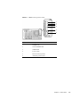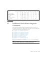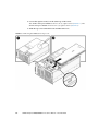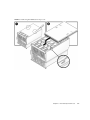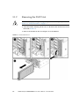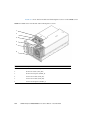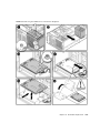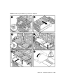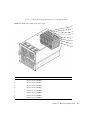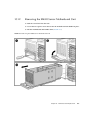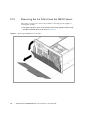
1
SPARC Enterprise M4000/M5000 Servers
Service Manual
Part No.: 819-2210-14,
Manual Code: C120-E352-07EN
December 2010, Revision A
Copyright © 2007, 2010, Oracle and/or its affiliates. All rights reserved.
FUJITSU LIMITED provided technical input and review on portions of this material.
Oracle and/or its affiliates and Fujitsu Limited each own or control intellectual property rights relating to products and technology described in this
document, and such products, technology and this document are protected by copyright laws, patents, and other intellectual property laws and
international treaties.
This document and the product and technology to which it pertains are distributed under licenses restricting their use, copying, distribution, and
decompilation. No part of such product or technology, or of this document, may be reproduced in any form by any means without prior written
authorization of Oracle and/or its affiliates and Fujitsu Limited, and their applicable licensors, if any. The furnishings of this document to you does not
give you any rights or licenses, express or implied, with respect to the product or technology to which it pertains, and this document does not contain or
represent any commitment of any kind on the part of Oracle or Fujitsu Limited, or any affiliate of either of them.
This document and the product and technology described in this document may incorporate third-party intellectual property copyrighted by and/or
licensed from the suppliers to Oracle and/or its affiliates and Fujitsu Limited, including software and font technology.
Per the terms of the GPL or LGPL, a copy of the source code governed by the GPL or LGPL, as applicable, is available upon request by the End User. Please
contact Oracle and/or its affiliates or Fujitsu Limited.
This distribution may include materials developed by third parties.
Parts of the product may be derived from Berkeley BSD systems, licensed from the University of California. UNIX is a registered trademark in the U.S. and
in other countries, exclusively licensed through X/Open Company, Ltd.
Oracle and Java are registered trademarks of Oracle and/or its affiliates. Fujitsu and the Fujitsu logo are registered trademarks of Fujitsu Limited.
All SPARC trademarks are used under license and are registered trademarks of SPARC International, Inc. in the U.S. and other countries. Products bearing
SPARC trademarks are based upon architectures developed by Oracle and/or its affiliates. SPARC64 is a trademark of SPARC International, Inc., used
under license by Fujitsu Microelectronics, Inc. and Fujitsu Limited. Other names may be trademarks of their respective owners.
United States Government Rights - Commercial use. U.S. Government users are subject to the standard government user license agreements of Oracle
and/or its affiliates and Fujitsu Limited and the applicable provisions of the FAR and its supplements.
Disclaimer: The only warranties granted by Oracle and Fujitsu Limited, and/or any affiliate of either of them in connection with this document or any
product or technology described herein are those expressly set forth in the license agreement pursuant to which the product or technology is provided.
EXCEPT AS EXPRESSLY SET FORTH IN SUCH AGREEMENT, ORACLE OR FUJITSU LIMITED, AND/OR THEIR AFFILIATES MAKE NO
REPRESENTATIONS OR WARRANTIES OF ANY KIND (EXPRESS OR IMPLIED) REGARDING SUCH PRODUCT OR TECHNOLOGY OR THIS
DOCUMENT, WHICH ARE ALL PROVIDED AS IS, AND ALL EXPRESS OR IMPLIED CONDITIONS, REPRESENTATIONS AND WARRANTIES,
INCLUDING WITHOUT LIMITATION ANY IMPLIED WARRANTY OF MERCHANTABILITY, FITNESS FOR A PARTICULAR PURPOSE OR NONINFRINGEMENT, ARE DISCLAIMED, EXCEPT TO THE EXTENT THAT SUCH DISCLAIMERS ARE HELD TO BE LEGALLY INVALID. Unless
otherwise expressly set forth in such agreement, to the extent allowed by applicable law, in no event shall Oracle or Fujitsu Limited, and/or any of their
affiliates have any liability to any third party under any legal theory for any loss of revenues or profits, loss of use or data, or business interruptions, or for
any indirect, special, incidental or consequential damages, even if advised of the possibility of such damages.
DOCUMENTATION IS PROVIDED “AS IS” AND ALL EXPRESS OR IMPLIED CONDITIONS, REPRESENTATIONS AND WARRANTIES,
INCLUDING ANY IMPLIED WARRANTY OF MERCHANTABILITY, FITNESS FOR A PARTICULAR PURPOSE OR NON-INFRINGEMENT, ARE
DISCLAIMED, EXCEPT TO THE EXTENT THAT SUCH DISCLAIMERS ARE HELD TO BE LEGALLY INVALID.
Please
Recycle
Copyright © 2007, 2010, Oracle et/ou ses sociétés affiliées. Tous droits réservés.
FUJITSU LIMITED a fourni et vérifié des données techniques de certaines parties de ce composant.
Oracle et/ou ses sociétés affiliées et Fujitsu Limited détiennent et contrôlent chacune des droits de propriété intellectuelle relatifs aux produits et
technologies décrits dans ce document. De même, ces produits, technologies et ce document sont protégés par des lois sur le copyright, des brevets,
d’autres lois sur la propriété intellectuelle et des traités internationaux.
Ce document, le produit et les technologies afférents sont exclusivement distribués avec des licences qui en restreignent l’utilisation, la copie, la
distribution et la décompilation. Aucune partie de ce produit, de ces technologies ou de ce document ne peut être reproduite sous quelque forme que ce
soit, par quelque moyen que ce soit, sans l’autorisation écrite préalable d’Oracle et/ou ses sociétés affiliées et de Fujitsu Limited, et de leurs éventuels
bailleurs de licence. Ce document, bien qu’il vous ait été fourni, ne vous confère aucun droit et aucune licence, expresses ou tacites, concernant le produit
ou la technologie auxquels il se rapporte. Par ailleurs, il ne contient ni ne représente aucun engagement, de quelque type que ce soit, de la part d’Oracle ou
de Fujitsu Limited, ou des sociétés affiliées de l’une ou l’autre entité.
Ce document, ainsi que les produits et technologies qu’il décrit, peuvent inclure des droits de propriété intellectuelle de parties tierces protégés par
copyright et/ou cédés sous licence par des fournisseurs à Oracle et/ou ses sociétés affiliées et Fujitsu Limited, y compris des logiciels et des technologies
relatives aux polices de caractères.
Conformément aux conditions de la licence GPL ou LGPL, une copie du code source régi par la licence GPL ou LGPL, selon le cas, est disponible sur
demande par l’Utilisateur final. Veuillez contacter Oracle et/ou ses sociétés affiliées ou Fujitsu Limited.
Cette distribution peut comprendre des composants développés par des parties tierces.
Des parties de ce produit peuvent être dérivées des systèmes Berkeley BSD, distribués sous licence par l’Université de Californie. UNIX est une marque
déposée aux États-Unis et dans d’autres pays, distribuée exclusivement sous licence par X/Open Company, Ltd.
Oracle et Java sont des marques déposées d’Oracle Corporation et/ou de ses sociétés affiliées. Fujitsu et le logo Fujitsu sont des marques déposées de
Fujitsu Limited.
Toutes les marques SPARC sont utilisées sous licence et sont des marques déposées de SPARC International, Inc., aux États-Unis et dans d’autres pays. Les
produits portant la marque SPARC reposent sur des architectures développées par Oracle et/ou ses sociétés affiliées. SPARC64 est une marque de SPARC
International, Inc., utilisée sous licence par Fujitsu Microelectronics, Inc. et Fujitsu Limited. Tout autre nom mentionné peut correspondre à des marques
appartenant à d’autres propriétaires.
United States Government Rights - Commercial use. U.S. Government users are subject to the standard government user license agreements of Oracle
and/or its affiliates and Fujitsu Limited and the applicable provisions of the FAR and its supplements.
Avis de non-responsabilité : les seules garanties octroyées par Oracle et Fujitsu Limited et/ou toute société affiliée de l’une ou l’autre entité en rapport
avec ce document ou tout produit ou toute technologie décrits dans les présentes correspondent aux garanties expressément stipulées dans le contrat de
licence régissant le produit ou la technologie fournis. SAUF MENTION CONTRAIRE EXPRESSÉMENT STIPULÉE DANS CE CONTRAT, ORACLE OU
FUJITSU LIMITED ET LES SOCIÉTÉS AFFILIÉES À L’UNE OU L’AUTRE ENTITÉ REJETTENT TOUTE REPRÉSENTATION OU TOUTE GARANTIE,
QUELLE QU’EN SOIT LA NATURE (EXPRESSE OU IMPLICITE) CONCERNANT CE PRODUIT, CETTE TECHNOLOGIE OU CE DOCUMENT,
LESQUELS SONT FOURNIS EN L’ÉTAT. EN OUTRE, TOUTES LES CONDITIONS, REPRÉSENTATIONS ET GARANTIES EXPRESSES OU TACITES, Y
COMPRIS NOTAMMENT TOUTE GARANTIE IMPLICITE RELATIVE À LA QUALITÉ MARCHANDE, À L’APTITUDE À UNE UTILISATION
PARTICULIÈRE OU À L’ABSENCE DE CONTREFAÇON, SONT EXCLUES, DANS LA MESURE AUTORISÉE PAR LA LOI APPLICABLE. Sauf mention
contraire expressément stipulée dans ce contrat, dans la mesure autorisée par la loi applicable, en aucun cas Oracle ou Fujitsu Limited et/ou l’une ou
l’autre de leurs sociétés affiliées ne sauraient être tenues responsables envers une quelconque partie tierce, sous quelque théorie juridique que ce soit, de
tout manque à gagner ou de perte de profit, de problèmes d’utilisation ou de perte de données, ou d’interruptions d’activités, ou de tout dommage
indirect, spécial, secondaire ou consécutif, même si ces entités ont été préalablement informées d’une telle éventualité.
LA DOCUMENTATION EST FOURNIE « EN L’ÉTAT » ET TOUTE AUTRE CONDITION, DÉCLARATION ET GARANTIE, EXPRESSE OU TACITE, EST
FORMELLEMENT EXCLUE, DANS LA MESURE AUTORISÉE PAR LA LOI EN VIGUEUR, Y COMPRIS NOTAMMENT TOUTE GARANTIE
IMPLICITE RELATIVE À LA QUALITÉ MARCHANDE, À L’APTITUDE À UNE UTILISATION PARTICULIÈRE OU À L’ABSENCE DE
CONTREFAÇON.
Contents
Preface
1.
2.
xvii
Safety and Tools
1–1
1.1
Safety Precautions
1–1
1.2
System Precautions
1–2
1.2.1
Electrical Safety Precautions
1.2.2
Equipment Rack Safety Precautions
1.2.3
Filler Boards and Filler Panels
1.2.4
Handling Components
Fault Isolation
1–2
1–2
1–3
1–3
2–1
2.1
Determining Which Diagnostics Tools to Use
2.2
Checking the Server and System Configuration
2.2.1
2.2.3
2.3
2–4
Checking the Hardware Configuration and FRU Status
2.2.1.1
2.2.2
2–1
Checking the Hardware Configuration
2–5
Checking the Software and Firmware Configuration
2.2.2.1
Checking the Software Configuration
2.2.2.2
Checking the Firmware Configuration
Downloading the Error Log Information
Operator Panel
2–4
2–6
2–7
2–7
2–8
2–8
v
2.4
Error Conditions
2.4.1
Predictive Self-Healing Tools
2.4.2
Monitoring Output
2.4.3
Messaging Output
2–17
LED Functions
2.6
Using the Diagnostic Commands
2–18
2–21
2.6.1
Using the showlogs Command
2.6.2
Using the fmdump Command
2.6.4
2.7
2–14
2–17
2.5
2.6.3
2–21
2–22
2.6.2.1
fmdump -V Command
2–22
2.6.2.2
fmdump -e Command
2–23
Using the fmadm faulty Command
2–23
2.6.3.1
fmadm repair Command
2–23
2.6.3.2
fmadm config Command
Using the fmstat Command
2–24
2–24
Traditional Oracle Solaris Diagnostic Commands
2.7.1
Using the iostat Command
2.7.1.1
2.7.2
2.7.3
Options
Options
2–32
2–33
2–34
2–34
Using the ps Command
2.7.6.1
2.7.7
Options
2–30
2–30
Using the ping Command
2.7.5.1
2.7.6
Options
2–27
2–27
Using the netstat Command
2.7.4.1
2.7.5
Options
2–26
2–26
Using the prtconf Command
2.7.3.1
2.7.4
Options
Using the prtdiag Command
2.7.2.1
vi
2–14
2–35
2–35
Using the prstat Command
2–36
SPARC Enterprise M4000/M5000 Servers Service Manual • December 2010
2–25
2.7.7.1
2.8
Other Issues
2.8.1
3.
3.1
3–1
Tape Drive Unit
FRU Replacement Method
4.2
Active Replacement
4–1
4–4
4.2.1
Removing a FRU From a Domain
4.2.2
Removing and Replacing a FRU
4.2.3
Adding a FRU Into a Domain
4.2.4
Verifying Hardware Operation
Hot Replacement
4–4
4–5
4–5
4–6
4–6
4.3.1
Removing and Replacing a FRU
4.3.2
Verifying Hardware Operation
4–7
4–9
Cold Replacement (Powering the Server Off and On)
4–12
4.4.1
Powering the Server Off Using Software
4–12
4.4.2
Powering the Server On Using Software
4–13
4.4.3
Powering the Server Off Manually
4–14
4.4.4
Powering the Server On Manually
4–14
4.4.5
Verifying Hardware Operation
Internal Components Access
5.2
3–1
4–1
4.1
5.1
2–37
Cleaning the Tape Drive Unit
FRU Replacement Preparation
4.4
5.
Can’t Locate Boot Device
3–1
4.3
2–36
2–37
Periodic Maintenance
3.1.1
4.
Options
4–15
5–1
Sliding the Server In and Out to the Fan Stop
5–1
5.1.1
Sliding the Server Out of the Equipment Rack
5.1.2
Sliding the Server Into the Equipment Rack
Top Cover Remove and Replace
5–2
5–4
5–5
Contents
vii
5.3
6.
Removing the Top Cover
5–5
5.2.2
Replacing the Top Cover
5–8
Fan Cover Remove and Replace
6.2
5–8
5.3.1
Removing the Fan Cover
5–8
5.3.2
Replacing the Fan Cover
5–10
Storage Devices Replacement
6.1
viii
5.2.1
6–1
Hard Disk Drive Replacement
6–1
6.1.1
Accessing the Hard Disk Drive
6–4
6.1.2
Removing the Hard Disk Drive
6–4
6.1.3
Installing the Hard Disk Drive
6.1.4
Securing the Server
6.1.5
Accessing the Hard Disk Drive Backplane of the M4000 Server
6–6
6.1.6
Removing the Hard Disk Drive Backplane of the M4000 Server
6–6
6.1.7
Installing the Hard Disk Drive Backplane of the M4000 Server
6–7
6.1.8
Securing the Server
6.1.9
Accessing the Hard Disk Drive Backplane of the M5000 Server
6–9
6.1.10
Removing the Hard Disk Drive Backplane of the M5000 Server
10
6–
6.1.11
Installing the Hard Disk Drive Backplane of the M5000 Server
10
6.1.12
Securing the Server
6–5
6–5
6–8
6–11
CD-RW/DVD-RW Drive Unit (DVDU) Replacement
6–12
6.2.1
Identifying the Type of CD-RW/DVD-RW Drive Unit
6–15
6.2.2
Accessing the CD-RW/DVD-RW Drive Unit
6–16
6.2.3
Removing the CD-RW/DVD-RW Drive Unit
6–16
6.2.4
Installing the CD-RW/DVD-RW Drive Unit
6.2.5
Securing the Server
6.2.6
Accessing the CD-RW/DVD-RW Drive Backplane of the M4000
Server 6–18
6–17
6–17
SPARC Enterprise M4000/M5000 Servers Service Manual • December 2010
6–
6.3
7.
6.2.7
Removing the CD-RW/DVD-RW Drive Backplane of the M4000
Server 6–18
6.2.8
Installing the CD-RW/DVD-RW Drive Backplane of the M4000
Server 6–19
6.2.9
Securing the Server
6.2.10
Accessing the CD-RW/DVD-RW Drive Backplane of the M5000
Server 6–20
6.2.11
Removing the CD-RW/DVD-RW Drive Backplane of the M5000
Server 6–21
6.2.12
Installing the CD-RW/DVD-RW Drive Backplane of the M5000
Server 6–21
6.2.13
Securing the Server
Tape Drive Unit Replacement
6–22
6–23
6.3.1
Accessing the Tape Drive Unit
6–26
6.3.2
Removing the Tape Drive Unit
6–26
6.3.3
Installing the Tape Drive Unit
6.3.4
Securing the Server
6.3.5
Accessing the Tape Drive Backplane of the M4000 Server
6–28
6.3.6
Removing the Tape Drive Backplane of the M4000 Server
6–29
6.3.7
Installing the Tape Drive Backplane of the M4000 Server
6.3.8
Securing the Server
6.3.9
Accessing the Tape Drive Backplane of the M5000 Server
6–31
6.3.10
Removing the Tape Drive Backplane of the M5000 Server
6–32
6.3.11
Installing the Tape Drive Backplane of the M5000 Server
6.3.12
Securing the Server
Power Systems Replacement
7.1
6–19
6–27
6–27
6–29
6–30
6–32
6–33
7–1
Power Supply Unit Replacement
7–1
7.1.1
Accessing the Power Supply Unit
7–4
7.1.2
Removing the Power Supply Unit
7–4
7.1.3
Installing the Power Supply Unit
7–5
Contents
ix
7.1.4
8.
I/O Unit Replacement
8.1
8.2
8.3
8.4
9.
x
Securing the Server
7–5
8–1
PCI Cassette Replacement
8–4
8.1.1
Accessing the PCI Cassette
8–5
8.1.2
Removing the PCI Cassette
8–5
8.1.3
Installing the PCI Cassette
8.1.4
Securing the Server
PCI Card Replacement
8–7
8–7
8.2.1
Removing the PCI Card
8.2.2
Installing the PCI Card
I/O Unit Replacement
8–6
8–7
8–8
8–10
8.3.1
Accessing the I/O Unit
8–10
8.3.2
Removing the I/O Unit
8–10
8.3.3
Installing the I/O Unit
8.3.4
Securing the Server
8–11
8–12
I/O Unit DC-DC Converter Replacement
8–12
8.4.1
Accessing the I/O Unit DC-DC Converter (DDC_A#0 or
DDC_B#0) 8–14
8.4.2
Removing the I/O Unit DC-DC Converter (DDC_A #0 or DDC_B
#0) 8–14
8.4.3
Installing the I/O Unit DC-DC Converter (DDC_A #0 or DDC_B
#0) 8–17
8.4.4
Securing the Server
8.4.5
Accessing the I/O Unit DC-DC Converter Riser
8–21
8.4.6
Removing the I/O Unit DC-DC Converter Riser
8–22
8.4.7
Replacing the I/O Unit DC-DC Converter Riser
8–24
8.4.8
Securing the Server
XSCF Unit Replacement
8–21
8–24
9–1
SPARC Enterprise M4000/M5000 Servers Service Manual • December 2010
9.1
10.
XSCF Unit Replacement
9.1.1
Accessing the XSCF Unit
9–3
9.1.2
Removing the XSCF Unit
9–4
9.1.3
Installing the XSCF Unit
9.1.4
Securing the Server
Fan Modules Replacement
10.1
9–1
9–5
9–5
10–1
Fan Module Replacement
10–1
10.1.1
Accessing the 60-mm Fan Module
10–4
10.1.2
Removing the 60-mm Fan Module
10–5
10.1.3
Installing the 60-mm Fan Module
10.1.4
Securing the Server
10.1.5
Accessing the 172-mm Fan Module
10–7
10.1.6
Removing the 172-mm Fan Module
10–8
10.1.7
Installing the 172-mm Fan Module
10.1.8
Securing the Server
10.1.9
Accessing the 60-mm Fan Backplane
10–10
10.1.10 Removing the 60-mm Fan Backplane
10–11
10–6
10–6
10–9
10.1.11 Installing the 60-mm Fan Backplane
10.1.12 Securing the Server
10–9
10–12
10–12
10.1.13 Accessing the SPARC Enterprise M4000 172-mm Fan Backplane
10–13
10.1.14 Removing the SPARC Enterprise M4000 172-mm Fan Backplane
10–13
10.1.15 Installing the M4000 Server 172-mm Fan Backplane
10.1.16 Securing the Server
10–16
10–16
10.1.17 Accessing the M5000 Server 172-mm Fan Backplane
10–17
10.1.18 Removing the M5000 Server 172-mm Fan Backplane
10–17
10.1.19 Installing the M5000 Server 172-mm Fan Backplane
10.1.20 Securing the Server
10–20
10–20
Contents
xi
11.
Memory Board Replacement
11.1
11.2
12.
Memory Board Replacement
12.2
Accessing the Memory Board
11–4
11.1.2
Removing the Memory Board
11–5
11.1.3
Installing the Memory Board
11.1.4
Securing the Server
DIMM Replacement
11–6
11–6
11–7
11.2.1
Confirmation of DIMM Information
11.2.2
Memory Installation Configuration Rules
11.2.3
Installing Memory:
11.2.4
Accessing the DIMMs
11–10
11.2.5
Removing the DIMMs
11–11
11.2.6
Installing the DIMMs
11.2.7
Securing the Server
11–12
11–12
12–1
Accessing the CPU Module
12–4
12.1.2
Removing the CPU Module
12–5
12.1.3
Installing the CPU Module
12.1.4
Securing the Server
12–6
12–6
12–7
SPARC64 VII/SPARC64 VII+ CPU Modules Added to a New
Domain 12–8
▼
12.2.2
11–9
11–10
12.1.1
CPU Upgrade
11–8
12–1
CPU Module Replacement
12.2.1
Adding a SPARC64 VII/SPARC64 VII+ CPU Module to a New
Domain 128
SPARC64 VII/SPARC64 VII+ Processors Added to an Existing
Domain 12–11
▼
xii
11–1
11.1.1
CPU Module Replacement
12.1
11–1
Preparing to Add SPARC64 VII/SPARC64 VII+ Processors to an
Existing Domain 1211
SPARC Enterprise M4000/M5000 Servers Service Manual • December 2010
▼
Adding a SPARC64 VII/SPARC64 VII+ CPU Module to a Domain
Configured With
SPARC64 VI 12-13
12.2.3
13.
Motherboard Unit Replacement
13.1
13.2
13.3
14.
Upgrading a SPARC64 VI CPU Module to SPARC64 VII/SPARC64
VII+ on an Existing Domain 12–15
13–1
Motherboard Unit Replacement
13–1
13.1.1
Accessing the M4000 Server Motherboard Unit
13–4
13.1.2
Removing the M4000 Server Motherboard Unit
13–5
13.1.3
Installing the M4000 Server Motherboard Unit
13.1.4
Securing the Server
13.1.5
Accessing the M5000 Server Motherboard Unit
13–7
13.1.6
Removing the M5000 Server Motherboard Unit
13–8
13.1.7
Installing the M5000 Server Motherboard Unit
13–10
13.1.8
Securing the Server
13–6
13–6
13–11
DC-DC Converter Replacement
13–12
13.2.1
Accessing the M4000 Server DC-DC Converter
13–14
13.2.2
Removing the M4000 Server DC-DC Converter
13–15
13.2.3
Installing the M4000 Server DC-DC Converter
13.2.4
Securing the Server
13.2.5
Accessing the M5000 Server DC-DC Converter
13–17
13.2.6
Removing the M5000 Server DC-DC Converter
13–18
13.2.7
Installing the M5000 Server DC-DC Converter
13.2.8
Securing the Server
13–18
Motherboard Unit Upgrade
13–19
13–16
13–16
13–18
13.3.1
Notes on Upgrading
13.3.2
Replacing a Motherboard Unit as an Upgrade in an Existing
Domain 13–20
Backplane Unit Replacement
13–19
14–1
Contents
xiii
14.1
15.
Backplane Unit Replacement
14.1.1
Accessing the M4000 Server Backplane Unit
14–3
14.1.2
Removing the M4000 Server Backplane Unit
14–5
14.1.3
Installing the M4000 Server Backplane Unit
14.1.4
Securing the Server
14.1.5
Accessing the M5000 Server Backplane Unit
14–9
14.1.6
Removing the M5000 Server Backplane Unit
14–10
14.1.7
Installing the M5000 Server Backplane Unit
14.1.8
Securing the Server
Operator Panel Replacement
15–1
15.2
Accessing the Operator Panel
15–1
15–4
15.2.1
Removing the Operator Panel
15.2.2
Installing the Operator Panel
15.2.3
Securing the Server
Server Configuration
C. FRU List
15–4
15–7
15–7
A–1
B. Rules for System Configuration
xiv
14–12
Operator Panel Replacement
A. Components List
B–1
B–1
C–1
C.1
Server Overview
C.2
System Boards
C–1
C–3
C.2.1
Motherboard Unit
C.2.2
CPU Module
C.2.3
Memory Board
C.3
Backplane Unit
C.4
I/O Unit
14–7
14–8
15.1
B.1
14–1
C–3
C–4
C–5
C–6
C–6
SPARC Enterprise M4000/M5000 Servers Service Manual • December 2010
14–12
C.5
Power
C–7
C.6
FAN Module
C.7
eXtended System Control Facility Unit
C.8
Drives
C–8
C–10
C.8.1
Hard Disk Drive
C–10
C.8.2
CD-RW/DVD-RW Drive Unit (DVDU)
C.8.3
Tape Drive Unit (TAPEU)
D. External Interface Specifications
D–1
Serial Port
D.2
UPC (UPS Control) Port
D.3
USB Port
D.4
Connection Diagram for Serial Cable
E. UPS Controller
D–2
D–3
D–3
Overview
E.2
Signal Cables
E.3
Signal Line Configuration
E–2
E.4
Power Supply Conditions
E–3
E–1
Input circuit
E.4.2
Output circuit
E.5
UPS Cable
E.6
UPC Connector
F.2
E–3
E–4
E–4
E–5
F–1
M4000 and M5000 Servers Air Filter
F–2
Command Operations Procedures
F–2
Air Filter Installation for the M4000 Server
F–3
F.2.1
F.3
E–1
E.4.1
F.1.1
D–4
E–1
E.1
F. Air Filters
C–11
C–11
D.1
F.1
C–9
Removing the Air Filter From the M4000 Server
Air Filter Installation for the M5000 Server
F–8
F–9
Contents
xv
F.3.1
Removing the Air Filter from the M5000 Server
F.3.2
Servicing the Air Filter
G. Abbreviations
Index
xvi
F–14
G–1
Index–1
SPARC Enterprise M4000/M5000 Servers Service Manual • December 2010
F–13
Preface
This service manual describes how to service the SPARC Enterprise M4000/M5000
servers from Oracle and Fujitsu. This document is intended for authorized service
providers. References herein to the M4000 server or M5000 server are references to
the SPARC Enterprise M4000 or SPARC Enterprise M5000 server.
This document is written for maintenance providers who have received formal
service training. A single engineer service model is used for servicing SPARC
Enterprise M4000/M5000 midrange servers with one exception: When the
motherboard of a SPARC Enterprise M5000 server must be removed and that server
is mounted above waist high in the rack, then two engineers or a platform must be
used for safety.
This section explains:
■
“SPARC Enterprise M4000/M5000 Servers Documentation” on page xviii
■
“Text Conventions” on page xix
■
“Notes on Safety” on page xx
■
“Documentation Feedback” on page xx
xvii
SPARC Enterprise M4000/M5000
Servers Documentation
For the web location of all SPARC Enterprise M4000/M5000 servers documents, refer
to the SPARC Enterprise M4000/M5000 Servers Getting Started Guide packaged with
your server.
Product notes are available on the website only. Please check for the most recent
update for your product.
Note – For Sun Oracle software-related manuals (Oracle Solaris OS, and so on), go
to: http://docs.sun.com
Book Titles
Sun/Oracle
Fujitsu
SPARC Enterprise M4000/M5000 Servers Site Planning Guide
819-2205
C120-H015
SPARC Enterprise Equipment Rack Mounting Guide
819-5367
C120-H016
821-3045
C120-E345
SPARC Enterprise M4000/M5000 Servers Overview Guide
819-2204
C120-E346
SPARC Enterprise M3000/M4000/M5000/M8000/M9000 Servers Important
Legal and Safety Information
821-2098
C120-E633
SPARC Enterprise M4000/M5000 Servers Safety and Compliance Manual
819-2203
C120-E348
External I/O Expansion Unit Safety and Compliance Guide
819-1143
C120-E457
SPARC Enterprise M4000 Server Unpacking Guide
821-3043
C120-E349
SPARC Enterprise M5000 Server Unpacking Guide
821-3044
C120-E350
SPARC Enterprise M4000/M5000 Servers Installation Guide
819-2211
C120-E351
SPARC Enterprise M4000/M5000 Servers Service Manual
819-2210
C120-E352
External I/O Expansion Unit Installation and Service Manual
819-1141
C120-E329
SPARC Enterprise M/3000/4000/M5000/M8000/M9000 Servers
Administration Guide
821-2794
C120-E331
SPARC Enterprise M/3000/4000/M5000/M8000/M9000 Servers XSCF User’s 821-2797
Guide
C120-E332
SPARC Enterprise M4000/M5000 Servers Getting Started
Guide*
SPARC Enterprise M3000/4000/M5000/M8000/M9000 Servers XSCF
Reference Manual
xviii
Varies per release Varies per release
SPARC Enterprise M4000/M5000 Servers Service Manual • December 2010
Book Titles
Sun/Oracle
Fujitsu
SPARC Enterprise M4000/M5000/M8000/M9000 Servers Dynamic
Reconfiguration (DR) User’s Guide
821-2796
C120-E335
SPARC Enterprise M4000/M5000/M8000/M9000 Servers Capacity on
Demand (COD) User’s Guide
821-2795
C120-E336
SPARC Enterprise M3000/M4000/M5000/M8000/M9000 Servers Product
Notes†
Varies per release Varies per release
SPARC Enterprise M4000/M5000 Servers Product Notes
Varies per release Varies per release
External I/O Expansion Unit Product Notes
819-5324
C120-E456
SPARC Enterprise M3000/M4000/M5000/M8000/M9000 Servers Glossary
821-2800
C120-E514
* All getting started guides are printed documents.
† For XCP version 1100 or later
Text Conventions
This manual uses the following fonts and symbols to express specific types of
information.
Fonts/symbols
Meaning
Example
AaBbCc123
What you type, when contrasted
with on-screen computer output.
This font represents the example of
command input in the frame.
XSCF> adduser jsmith
AaBbCc123
The names of commands, files, and
directories; on-screen computer
output.
This font represents the example of
command input in the frame.
XSCF> showuser -P
User Name:
jsmith
Privileges:
useradm
auditadm
Italic
Indicates the name of a reference
manual
See the SPARC Enterprise
M/3000/4000/M5000/M8000/M900
0 Servers XSCF User’s Guide.
""
Indicates names of chapters,
sections, items, buttons, or menus
See Chapter 2, "System Features."
Preface
xix
Notes on Safety
Read the following documents thoroughly before using or handling any SPARC
Enterprise M4000/M5000 server.
■
SPARC Enterprise M3000/M4000/M5000/M8000/M9000 Servers Important Legal and
Safety Information
■
SPARC Enterprise M4000/M5000 Servers Safety and Compliance Guide
Documentation Feedback
If you have any comments or requests regarding this document, go to the following
web sites.
■
For Oracle users:
http://docs.sun.com
■
For Fujitsu users in U.S.A., Canada, and Mexico:
http://www.computers.us.fujitsu.com/www/support_servers.shtml?s
upport/servers
■
For Fujitsu users in other countries, refer to this SPARC Enterprise contact:
http://www.fujitsu.com/global/contact/computing/sparce_index.html
xx
SPARC Enterprise M4000/M5000 Servers Service Manual • December 2010
1
CHAPTER
Safety and Tools
This chapter describes safety and tools information. The information is organized
into the following topics:
1.1
■
Section 1.1, “Safety Precautions” on page 1-1
■
Section 1.2, “System Precautions” on page 1-2
Safety Precautions
To protect both yourself and the equipment, observe the following safety
precautions.
TABLE 1-1
ESD Precautions
Item
Problem
Precaution
ESD
jack/wrist or
foot strap
Electrostatic
Discharge (ESD)
Connect the ESD connector to your server and wear the wrist strap or foot
strap when handling printed circuit boards. There are two antistatic strap
attachment points on the chassis:
1. Right side towards the front
2. Left side towards the rear
ESD mat
ESD
An approved ESD mat provides protection from static damage when used
with a wrist strap or foot strap. The mat also cushions and protects small
parts that are attached to printed circuit boards.
ESD
packaging
box
ESD
Place the board or component in the ESD safe packaging box after you
remove it.
1-1
Caution – Attach the cord of the antistatic wrist strap directly to the server. Do not
attach the antistatic wrist strap to the ESD mat connection.
The antistatic wrist strap and any components you remove must be at the same
potential.
1.2
System Precautions
For your protection, observe the following safety precautions when servicing your
equipment:
1.2.1
■
Follow all cautions, warnings, and instructions marked on the equipment.
■
Never push objects of any kind through openings in the equipment, as they might
touch dangerous voltage points or short out components that could result in fire
or electric shock.
■
Refer servicing of equipment to qualified personnel.
Electrical Safety Precautions
Ensure that the voltage and frequency of the power outlet to be used match the
electrical rating labels on the equipment.
Wear antistatic wrist straps when handling any magnetic storage devices,
system boards, or other printed circuit boards.
Use only properly grounded power outlets as described in the SPARC Enterprise
M4000/M5000 Servers Installation Guide.
Caution – Do not make mechanical or electrical modifications. The manufacturer is
not responsible for regulatory compliance of modified servers.
1.2.2
Equipment Rack Safety Precautions
All equipment racks should be anchored to the floor, ceiling, or to adjacent frames,
using the manufacturer’s instructions.
1-2
SPARC Enterprise M4000/M5000 Servers Service Manual • December 2010
Free-standing equipment racks should be supplied with a stabilizer feature, which
must be sufficient to support the weight of the server when extended on its slides.
This prevents instability during installation or service actions.
Where a stabilizer feature is not supplied and the equipment rack is not bolted to the
floor, a safety evaluation must be conducted by the installation or service engineer.
The safety evaluation determines stability when the server is extended on its slides,
prior to any installation or service activity.
Prior to installing the equipment rack on a raised floor, a safety evaluation must be
conducted by the installation or service engineer. The safety evaluation ensures that
the raised floor has sufficient strength to withstand the forces upon it when the
server is extended on its slides. The normal procedure in this case would be to fix the
rack through the raised floor to the concrete floor below, using a proprietary
mounting kit for the purpose.
Caution – If more than one server is installed in an equipment rack, service only one
server at a time.
1.2.3
Filler Boards and Filler Panels
Filler boards and panels, which are physically inserted into the server when a board
or module has been removed are used for EMI protection and for air flow.
1.2.4
Handling Components
Caution – There is a separate ground located on the rear of the server. It is
important to ensure that the server is properly grounded.
Caution – The server is sensitive to static electricity. To prevent damage to the
board, connect an antistatic wrist strap between you and the server.
Caution – The boards have surface-mount components that can be broken by flexing
the boards.
To minimize the amount of board flexing, observe the following precautions:
Chapter 1
Safety and Tools
1-3
■
Hold the board by the handle and finger hold panels, where the board stiffener is
located. Do not hold the board at the ends.
■
When removing the board from the packaging, keep the board vertical until you
lay it on the cushioned ESD mat.
■
Do not place the board on a hard surface. Use a cushioned antistatic mat. The
board connectors and components have very thin pins that bend easily.
■
Be careful of small component parts located on both sides of the board.
■
Do not use an oscilloscope probe on the components. The soldered pins are easily
damaged or shorted by the probe point.
■
Transport the board in its packaging box.
Caution – The heat sinks can be damaged by incorrect handling. Do not touch the
heat sinks while replacing or removing boards. If a heat sink is loose or broken,
obtain a replacement board. When storing or shipping a board, ensure that the heat
sinks have sufficient protection.
Caution – On the PCI cassette, when removing cables such as LAN cable, if your
finger can’t reach the latch lock of the connector, press the latch with a flathead
screwdriver to remove the cable. Forcing your finger into the clearance can cause
damage to the PCI card.
1-4
SPARC Enterprise M4000/M5000 Servers Service Manual • December 2010
CHAPTER
2
Fault Isolation
This chapter describes overview and fault diagnosis information. The information is
organized into the following topics:
2.1
■
Section 2.1, “Determining Which Diagnostics Tools to Use” on page 2-1
■
Section 2.2, “Checking the Server and System Configuration” on page 2-4
■
Section 2.3, “Operator Panel” on page 2-8
■
Section 2.4, “Error Conditions” on page 2-14
■
Section 2.5, “LED Functions” on page 2-18
■
Section 2.6, “Using the Diagnostic Commands” on page 2-21
■
Section 2.7, “Traditional Oracle Solaris Diagnostic Commands” on page 2-25
■
Section 2.8, “Other Issues” on page 2-37
Determining Which Diagnostics Tools to
Use
When a failure occurs, a message is often displayed on the monitor. Use the
flowcharts in FIGURE 2-1 and FIGURE 2-2 to find the correct methods for diagnosing
problems.
2-1
FIGURE 2-1
Diagnostic Method Flow Chart
No
2-2
SPARC Enterprise M4000/M5000 Servers Service Manual • December 2010
FIGURE 2-2
Diagnostic Method Flow Chart—Traditional Data Collection
Chapter 2
Fault Isolation
2-3
2.2
Checking the Server and System
Configuration
Before and after maintenance work, the state and configuration of the server and
components should be checked and the information saved. For recovery from a
problem, conditions related to the problem and the repair status must be checked.
The operating conditions must remain the same before and after maintenance.
A functioning server without any problems should not display any error conditions.
For example:
2.2.1
■
The syslog file should not display error messages.
■
The XSCF Shell command showhardconf does not display the * mark.
■
The administrative console should not display error messages.
■
The server processor logs should not display any error messages.
■
The Oracle Solaris Operating System message files should not indicate any
additional errors.
Checking the Hardware Configuration and FRU
Status
To replace a faulty component and perform the maintenance on the server it is
important to check and understand the hardware configuration of the server and the
state of each hardware component.
The hardware configuration refers to information that indicates to which layer a
component belongs in the hardware configuration.
The status of each hardware component refers to information on the condition of the
standard or optional component in the server: temperature, power supply voltage,
CPU operating conditions, and other times.
2-4
SPARC Enterprise M4000/M5000 Servers Service Manual • December 2010
The hardware configuration and the status of each hardware component can be
checked from the maintenance terminal using eXtended System Control Facility
(XSCF) Shell commands, as shown in the following table.
TABLE 2-1
Commands for Checking Hardware Configuration
Command
Description
showhardconf
Displays hardware configuration.
showstatus
Displays the status of a component. This command is used when
only a faulty component is checked.
showboards
Displays the status of devices and resources.
showdcl
Displays the hardware resource configuration information of a
domain.
showfru
Displays the setting information of a device.
Also some conditions can be checked based on the On or blinking state of the
component LEDs (see TABLE 2-3).
2.2.1.1
Checking the Hardware Configuration
Login authority is required to check the hardware configuration. The following
procedure for these checks can be made from the maintenance terminal:
1. Log in with the account of the XSCF hardware maintenance engineer.
2. Type showhardconf.
XSCF> showhardconf
The showhardconf command prints the hardware configuration information to
the screen. See the SPARC Enterprise M3000/M4000/M5000/M8000/M9000 Servers
XSCF User’s Guide for more detailed information.
Chapter 2
Fault Isolation
2-5
2.2.2
Checking the Software and Firmware
Configuration
The software and firmware configurations and versions affect the operation of the
server. To change the configuration or investigate a problem, check the latest
information and check for any problems in the software.
Software and firmware varies according to users:
■
The software configuration and version can be checked in the Oracle Solaris OS.
Refer to the Solaris 10 documentation for more information.
■
The firmware configuration and versions can be checked from the maintenance
terminal using XSCF Shell commands. Refer to the SPARC Enterprise
M3000/M4000/M5000/M8000/M9000 Servers XSCF User’s Guide for more detailed
information.
Check the software and firmware configuration information with assistance from the
system administrator. However, if you have received login authority from the system
administrator, the commands shown in the table can be used from the maintenance
terminal for these checks.
TABLE 2-2
2-6
Commands for Checking Software and Firmware Configuration
Command
Description
showrev(1M)
System administration command that displays information system
patches.
uname(1)
System administration command that outputs the current system
information.
version(8)
XSCF Shell command that outputs the current firmware version
information.
showhardconf(8)
XSCF Shell command that indicates information on components
mounted on the server.
showstatus(8)
XSCF Shell command that displays the status of a component. This
command is used when only a faulty component is to be checked.
SPARC Enterprise M4000/M5000 Servers Service Manual • December 2010
TABLE 2-2
2.2.2.1
Commands for Checking Software and Firmware Configuration (Continued)
Command
Description
showboards(8)
XSCF Shell command that indicates information on eXtended system
board (XSB). It can indicate information on XSB that belongs to the
specified domain and information on all XSBs mounted. The
eXtended System Board (XSB) combines the hardware resources of a
physical system board. The SPARC Enterprise servers can generate
one (Uni-XSB) or four (Quad-XSB) XSB(s) from one physical system
board.
showdcl(8)
XSCF Shell command that displays the configuration information of a
domain (hardware resource information).
showfru(8)
XSCF Shell command that displays the setting information of a
device.
Checking the Software Configuration
The following procedure for these checks can be made from the domain console:
1. Type showrev.
# showrev
The showrev command prints the system configuration information to the
screen.
2.2.2.2
Checking the Firmware Configuration
Login authority is required to check the firmware configuration. The following
procedure for these checks can be made from the maintenance terminal:
1. Log in with the account of the XSCF hardware maintenance engineer.
2. Type version(8).
XSCF> version(8)
The version(8) command prints the firmware version information to the
screen. See the SPARC Enterprise M3000/M4000/M5000/M8000/M9000 Servers XSCF
User’s Guide for more detailed information.
Chapter 2
Fault Isolation
2-7
2.2.3
Downloading the Error Log Information
If you want to download the error log information, use the XSCF log fetch function.
The eXtended System Control facility unit (XSCFU) has an interface with external
units so that a maintenance engineer can easily obtain useful maintenance
information such as error logs
Connect the maintenance terminal, and use the command-line interface (CLI) or
browser user interface (BUI) to issue a download instruction to the maintenance
terminal to download Error Log information over the XSCF-LAN.
2.3
Operator Panel
When no network connection is available the operator panel is used to start or stop
the server. The operator panel displays three LED status indicators, a Power switch,
and a security keyswitch. The panel is located on the front of the server, in the upper
right.
When the server is running, the Power and XSCF STANDBY LEDs (green) should be
lit and the CHECK LED (amber) should not be lit. If the CHECK LED is lit, search
the system logs to determine what is wrong.
The three LED status indicators on the operator panel provide the following:
■
General system status
■
System problem alerts
■
Location of the system fault
FIGURE 2-3 and FIGURE 2-4 show the operator panel.
2-8
SPARC Enterprise M4000/M5000 Servers Service Manual • December 2010
FIGURE 2-3
M4000 Server Operator Panel
1
2
3
4
5
6
l
Location Number
Component
1
POWER LED
2
XSCF STANDBY LED
3
CHECK LED
4
Power switch
5
Mode switch (keyswitch)
6
Antistatic ground socket
Chapter 2
Fault Isolation
2-9
FIGURE 2-4
M5000 Server Operator Panel
1
2
3
4
5
6
Location Number
Component
1
POWER LED
2
XSCF STANDBY LED
3
CHECK LED
4
Power switch
5
Mode switch (keyswitch)
6
Antistatic ground socket
Additional LEDs are located in various locations in the server. For more information
about LED indicator locations, see Section 2.5, “LED Functions” on page 2-18.
2-10
SPARC Enterprise M4000/M5000 Servers Service Manual • December 2010
The Operator panel LEDs operate as described in TABLE 2-3.
TABLE 2-3
Icon
Operator Panel LEDs and Switches
Name
Color
Description
Green
Indicates the server power status.
• On: Server has power.
• Off: Server is without power.
• Blinking: The power-off sequence is in progress.
XSCF
STANDBY
LED
Green
Indicates the readiness of the XSCF.
• On: XSCF unit is functioning normally.
• Off: XSCF unit is stopped.
• Blinking: Under system initialization after server
power-on, or under system power-on process.
CHECK LED
Amber
POWER LED
Power switch
Mode switch
(keyswitch)
Indicates that server detected a fault.
• On: Error detected that disables the startup.
• Off: Normal, or server power-off (power failure).
• Blinking: Indicates the position of fault.
Switch to direct server power on/power off.
The Locked setting:
• Normal key position. Power on is available with the
Power switch, but power off is not.
• Disables the Power switch to prevent unauthorized
users from powering the server on or off.
• The Locked position is the recommended setting for
normal day-to-day operations.
The Service setting:
• Service should be provided at this position.
• Power on and off is available with Power switch.
• The key cannot be pulled out at this position.
Chapter 2
Fault Isolation
2-11
The state displayed by LED combination is described in TABLE 2-4.
TABLE 2-4
State Display by LED Combination (Operator Panel)
LED
2-12
POWER
XSCF
STANDBY
CHECK
Description of the state
Off
Off
Off
The circuit breaker is switched off.
Off
Off
On
The circuit breaker is switched on.
Off
Blinking
Off
The XSCF is being initialized.
Off
Blinking
On
An error occurred in the XSCF.
Off
On
Off
The XSCF is on standby.
The system is waiting for power-on of the air
conditioning system.
On
On
Off
Warm-up standby processing is in progress
(power-on is delayed).
The power-on sequence is in progress.
The system is in operation.
Blinking
On
Off
The power-off sequence is in progress.
Fan termination is being delayed.
SPARC Enterprise M4000/M5000 Servers Service Manual • December 2010
The operator panel mode switch is used to set the operation mode. The operator panel
power switch is used to power on and off the server. TABLE 2-6 lists the settings and
corresponding functions of the mode switch on the operator panel.
TABLE 2-5
Switches (Operator Panel)
Name
Mode switch
Power switch
Description of Function
Used to set an operation mode for the server. Insert the special key that is under the
customer’s control, to switch between modes.
Locked
Normal operation mode.
The system can be powered on with the power switch, but it
cannot be powered off with the power switch.
The key can be pulled out at this key position.
Service
Mode for maintenance.
The system can only be powered on and off with the power
switch.
The key cannot be pulled out at this key position.
Maintenance is performed in Service mode while the server
is stopped.
Because remote power control and automatic power control
of the server are disabled in Service mode, unintentional
power on can be prevented.
Used to control the server power. Power on and power off are controlled by pressing this
switch in different patterns, as described below.
Holding down for a short time
(less than 4 seconds)
Regardless of the mode switch state, the server (all domains)
is powered on.
At this time, processing for waiting for facility (air
conditioners) power on and warm-up completion is skipped.
Holding down for a long time
in Service mode
(4 seconds or longer)
If power to the server is on (at least one domain is
operating), shutdown processing is executed for all domains
before the system is powered off.
If the system is being powered on, the power-on processing
is cancelled, and the system is powered off.
If the system is being powered off, the operation of the
Power switch is ignored, and the power-off processing is
continued.
Chapter 2
Fault Isolation
2-13
TABLE 2-6
Meanings of the Mode Switch
Function
Mode Switch
State Definition
Locked
Inhibition of Break Signal Reception
Enabled. Reception of the
Disabled
break signal can be enabled or
disabled for each domain
using setdomainmode.
Power On/Off by power switch
Only power on is enabled
2.4
Service
Enabled
Error Conditions
Always access the following web site first to interpret faults and obtain information
on FMA messages.
http://www.sun.com/msg
This web site can be used in the event of an Oracle Solaris or domain failure or to
look up specific FMA error messages it will not provide details on XSCF errors.
The web site directs you to provide the message ID that your software displayed. The
web site then provides knowledge articles about the fault and corrective action to
resolve the fault. The fault information and documentation at this web site is
updated regularly.
Predictive self-healing is an architecture and methodology for automatically
diagnosing, reporting, and handling software and hardware fault conditions. This
new technology lessens the time required to debug a hardware or software problem
and provides the administrator and technical support with detailed data about each
fault.
2.4.1
Predictive Self-Healing Tools
In the Solaris 10 software, the fault manager runs in the background. If a failure
occurs, the system software recognizes the error and attempts to determine what
hardware is faulty. The software also takes steps to prevent that component from
being used until it has been replaced. Some of the specific actions the software takes
include:
■
2-14
Receives telemetry information about problems detected by the system software.
SPARC Enterprise M4000/M5000 Servers Service Manual • December 2010
■
Diagnoses the problems.
■
Initiates pro-active self-healing activities. For example, the fault manager can
disable faulty components.
■
When possible, causes the faulty FRU to provide an LED indication of a fault in
addition to populating the system console messages with more details.
TABLE 2-7 shows a typical message generated when a fault occurs. The message
appears on your console and is recorded in the /var/adm/messages file.
Note – The message in TABLE 2-7 indicates that the fault has already been diagnosed.
Any corrective action that the system can perform has already taken place. If your
server is still running, it continues to run.
Chapter 2
Fault Isolation
2-15
TABLE 2-7
Predictive Self-Healing Message
Output Displayed
Description
Nov 1 16:30:20 dt88-292 EVENT-TIME: Tue Nov 1 16:30:20
PST 2005
EVENT-TIME: the time stamp of
the diagnosis.
Nov 1 16:30:20 dt88-292 PLATFORM: SUNW,A70, CSN: -,
HOSTNAME: dt88-292
PLATFORM: A description of the
server encountering the problem.
Nov 1 16:30:20 dt88-292 SOURCE: eft, REV: 1.13
SOURCE: Information on the
Diagnosis Engine used to
determine the fault.
Nov 1 16:30:20 dt88-292 EVENT-ID:
afc7e660-d609-4b2f-86b8-ae7c6b8d50c4
EVENT-ID: The Universally
Unique event ID for this fault.
Nov 1 16:30:20 dt88-292 DESC:
Nov 1 16:30:20 dt88-292 A problem was detected in the
PCI-Express subsystem
DESC: A basic description of the
failure.
Nov 1 16:30:20 dt88-292 Refer to
http://sun.com/msg/SUN4-8000-0Y for more information.
WEB SITE: Where to find specific
information and actions for this
fault.
Nov 1 16:30:20 dt88-292 AUTO-RESPONSE: One or more
device instances may be disabled.
AUTO-RESPONSE: What, if
anything, the system did to
alleviate any follow-on issues.
Nov 1 16:30:20 dt88-292 IMPACT: Loss of services
provided by the device instances associated with this
fault.
IMPACT: A description of what
that response might have done.
Nov 1 16:30:20 dt88-292 REC-ACTION: Schedule a repair
procedure to replace the affected device. Use Nov 1
16:30:20 dt88-292 fmdump -v -u EVENT_ID to identify the
device or contact Sun for support.
REC-ACTION: A short description
of what the system administrator
should do.
2-16
SPARC Enterprise M4000/M5000 Servers Service Manual • December 2010
2.4.2
Monitoring Output
To understand error conditions, collect the monitoring output information. For the
collection of the information, use the commands shown in TABLE 2-8.
TABLE 2-8
2.4.3
Commands for Checking the Monitoring Output
Command
Operand
Description
showlogs(8)
console
Displays console of Domain.
monitor
Logs messages that are displayed in the message window.
panic
Logs output to the console during a panic.
ipl
Collects console data generated during the period of the
power on of a domain to the completion of the operating
system start.
Messaging Output
To understand error conditions, collect messaging output information, use the
commands shown in TABLE 2-9.
TABLE 2-9
Commands for Checking the Messaging Output
Command
Operand
Description
showlogs
env
Displays the temperature history log. The environmental
temperature data and power status are indicated in 10-minute
intervals. the data is stored for a maximum of six months.
power
Displays the power and reset information.
event
Displays information reported to the operating system and
stored as event logs.
error
Displays error logs.
fmdump(1M)
fmdump(8)
Displays fault management architecture diagnostic results and
errors. It is provided as an Oracle Solaris command and XSCF
Shell command.
Each error message logged by the predictive self-healing architecture has a code
associated with it as well as a web address that can be followed to get the most
up-to-date course of action for dealing with that error.
Refer to the Oracle Solaris 10 documentation for more information on predictive
self-healing.
Chapter 2
Fault Isolation
2-17
2.5
LED Functions
LED lights help the user find the component and provide information on the state of
the component.
This section explains the LEDs of each component that are to be checked when a
component is replaced. Most components are equipped with LEDs that help indicate
which component has the error and an LED to indicate whether the component can
be removed.
Some components, such as DIMMs, do not have LEDs. The state of a component
without LEDs can be checked using the showhardconf and ioxadm XSCF Shell
commands from the maintenance terminal. See the SPARC Enterprise
M3000/M4000/M5000/M8000/M9000 Servers XSCF User’s Guide for more detailed
information.
TABLE 2-10 describes the LEDs and their functions.
TABLE 2-10
LED Name
Display and Meaning
READY (green)
Indicates whether the component is operating.
CHECK
(amber)
2-18
Component LEDs
On
Indicates that the component is operating. The component
cannot be disconnected and removed from the server while
the READY LED is On.
Blinking
Indicates that the component is being configured (or
disconnected).
For an XSCF unit it indicates that it is being initialized.
Off
Indicates that the component is stopped. The component can
be disconnected and replaced.
Indicates that the component contains an error or that the component is a
target for replacement.
On
Indicates that an error has been detected.
Blinking
Indicates that the component is ready to be replaced. The
blinking LED acts as a locator.
Off
Indicates no known error exists.
SPARC Enterprise M4000/M5000 Servers Service Manual • December 2010
TABLE 2-11 describes the components and their LEDs.
TABLE 2-11
Component LED Descriptions
Component
LED Type
LED Display
Meaning
XSCF unit
ACTIVE
On (green)
Indicates that the XSCF unit is active.
Off
Indicates that the XSCF unit is on standby.
On (green)
Indicates that the communication is being
performed through the LAN port.
Off
Indicates that no communication is being
performed through the LAN port.
On (amber)
Indicates that the communication speed for the
LAN port is 1G bps.
On (green)
Indicates that the communication speed for the
LAN port is 100M bps.
Off
Indicates that the communication speed for the
LAN port is 10M bps.
On (green)
Indicates that the power to the PCI slot is turned
on. The PCI card cannot be removed.
Off
Indicates that the power to the PCI slot is turned
off. The PCI card can be removed.
On (amber)
Indicates that an error occurred in the PCI slot.
Blinking (amber)
Indicates that the card in this PCI slot is a target
device for replacement.
Off
Indicates the normal state of the PCI slot.
XSCF unit and IO
(display part for
LAN)
ACTIVE
LINK SPEED
PCI slot
POWER
ATTENTION
Chapter 2
Fault Isolation
2-19
TABLE 2-11
Component LED Descriptions (Continued)
Component
LED Type
LED Display
Meaning
Power supply unit
(PSU)
READY
On (green)
Indicates that the power is turned on and being
supplied.
Blinking (green)
Indicates that the power is being supplied to the
power supply unit, but the power supply unit is
not turned on.
Off
Indicates that power is not being supplied to the
power supply unit.
On (amber)
Indicates that an error occurred in the power
supply unit.
Off
Indicates the normal state of the power supply
unit.
On (green)
Power supply unit has AC applied and is
supplying 12V.
Off
Indicates that AC is out of the specified
operating range and 12V is not being supplied
from the power supply unit.
On (green)
Power supply unit has AC applied and is
supplying 48V. Standby pinhole provides a
manual backup to turn off 48V power.
Off
Indicates that 48V is not being supplied from
the power supply unit.
On (amber)
Indicates that an error occurred.
Blinking (amber)
Indicates that the fan is a target device for
replacement.
CHECK
LED_AC
LED_DC
Fan
2-20
ATTENTION
SPARC Enterprise M4000/M5000 Servers Service Manual • December 2010
2.6
Using the Diagnostic Commands
After the message in TABLE 2-7 is displayed, you might desire more information about
the fault. For complete information about troubleshooting commands, refer to the
Oracle Solaris 10 man pages or the XSCF Shell man pages. This section describes
some details of the following commands:
2.6.1
■
showlogs
■
fmdump
■
fmadm
■
fmstat
Using the showlogs Command
The showlogs command displays the contents of a specified log in order of time
stamp starting with the oldest date. The showlogs command displays the following
logs:
■
error log
■
power log
■
event log
■
temperature and humidity record
■
monitoring message log
■
console message log
■
panic message log
■
IPL message log
An example of the showlogs output.
XSCF> showlogs error
Date: Oct 03 17:23:11 UTC 2006
Code: 80002000-ccff0000-0104340100000000
Status: Alarm
Occurred: Oct 03 17:23:10.868 UTC 2006
FRU: /FAN_A#0
Msg: Abnormal FAN rotation speed. Insufficient rotation
XSCF>
Chapter 2
Fault Isolation
2-21
2.6.2
Using the fmdump Command
The fmdump command can be used to display the contents of any log files associated
with the Oracle Solaris fault manager.
The fmdump command produces output similar to EXAMPLE 2-1. This example
assumes there is only one fault.
EXAMPLE 2-1
fmdump Output
# fmdump
TIME
UUID
SUNW-MSG-ID
Nov 02 10:04:15.4911 0ee65618-2218-4997-c0dc-b5c410ed8ec2 SUN4-8000-0Y
2.6.2.1
fmdump -V Command
You can obtain more detail by using the -V option.
# fmdump -V -u 0ee65618-2218-4997-c0dc-b5c410ed8ec2
TIME
UUID
Nov 02 10:04:15.4911 0ee65618-2218-4997-c0dc-b5c410ed8ec2
100% fault.io.fire.asic
FRU: hc://product-id=SUNW,A70/motherboard=0
rsrc: hc:///motherboard=0/hostbridge=0/pciexrc=0
SUNW-MSG-ID
SUN4-8000-0Y
At least three lines of new output are delivered to the user with the -V option.
2-22
■
The first line is a summary of information you have seen before in the console
message but includes the time stamp, the UUID and the Message-ID.
■
The second line is a declaration of the certainty of the diagnosis. In this case we
are 100 percent sure the failure is in the ASIC described. If the diagnosis might
involve multiple components you might see two lines here with 50% in each (for
example)
■
The FRU line declares the part that needs to be replaced to return the server to a
fully operational state.
■
The rsrc line describes which component was taken out of service as a result of
this fault.
SPARC Enterprise M4000/M5000 Servers Service Manual • December 2010
2.6.2.2
fmdump -e Command
To get information of the errors that caused this failure you can use the -e option, as
shown in the following example.
XSCF> fmdump -e
TIME
Oct 03 13:52:48.9532
Oct 03 13:52:48.9610
Oct 03 13:52:48.9674
Oct 03 13:52:48.9738
2.6.3
CLASS
ereport.fm.fmd.module
ereport.fm.fmd.module
ereport.fm.fmd.module
ereport.fm.fmd.module
Using the fmadm faulty Command
The fmadm faulty command can be used by administrators and service personnel
to view and modify system configuration parameters that are maintained by the
Oracle Solaris fault manager. The command is primarily used to determine the status
of a component involved in a fault, as shown in the following example.
# fmadm faulty
STATE RESOURCE / UUID
-------- -------------------------------------------------------degraded dev:////pci@1e,600000
0ee65618-2218-4997-c0dc-b5c410ed8ec2
# fmadm repair
0ee65618-2218-4997-c0dc-b5c410ed8ec2
The PCI device is degraded and is associated with the same UUID as seen above. You
might also see “faulted” states.
2.6.3.1
fmadm repair Command
If fmadm faulty occurs, the faulty FRU (CPU, memory, or I/O unit) is replaced,
and then the fmadm repair command needs to be executed to clear FRU
information on the domain. If the fmadam repair command is not executed, error
messages continue to be output.
Chapter 2
Fault Isolation
2-23
If fmadm faulty occurs, the FMA resource cache on the OS side can be cleared
without problems; the data in it need not match the hardware failure information
retained on the XSCF side.
# fmadm repair
STATE RESOURCE / UUID
-------- -------------------------------------------------------degraded dev:////pci@1e,600000
0ee65618-2218-4997-c0dc-b5c410ed8ec2
2.6.3.2
fmadm config Command
The fmadm config command output shows you the version numbers of the
diagnosis engines in use by your server, as well as their current state. You can check
these versions against information on the My Oracle Support web site to determine if
you are running the latest diagnostic engines, as shown in the following example.
XSCF> fmadm config
MODULE
eft
event-transport
faultevent-post
fmd-self-diagnosis
iox_agent
reagent
sysevent-transport
syslog-msgs
XSCF>
2.6.4
VERSION
1.16
2.0
1.0
1.0
1.0
1.1
1.0
1.0
STATUS
active
active
active
active
active
active
active
active
DESCRIPTION
eft diagnosis engine
Event Transport Module
Gate Reaction Agent for errhandd
Fault Manager Self-Diagnosis
IO Box Recovery Agent
Reissue Agent
SysEvent Transport Agent
Syslog Messaging Agent
Using the fmstat Command
The fmstat command can report statistics associated with the Oracle Solaris fault
manager. The fmstat command shows information about DE performance. In the
example below, the fmd-self-diagnosis DE (also seen in the console output) has
received an event which it accepted. A case is “opened” for that event and a
diagnosis is performed to “solve” the cause for the failure. See the following
example.
2-24
SPARC Enterprise M4000/M5000 Servers Service Manual • December 2010
XSCF> fmstat
module
ev_recv ev_acpt wait svc_t %w %b open solve
eft
0
0 0.0
0.0
0
0
0
0
event-transport
0
0 0.0
0.0
0
0
0
0
faultevent-post
2
0 0.0
8.9
0
0
0
0
fmd-self-diagnosis
24
24 0.0 352.1
0
0
1
0
iox_agent
0
0 0.0
0.0
0
0
0
0
reagent
0
0 0.0
0.0
0
0
0
0
sysevent-transport
0
0 0.0 8700.4
0
0
0
0
syslog-msgs
0
0 0.0
0.0
0
0
0
0
XSCF>
2.7
memsz
3.3M
6.4K
0
24b
0
0
0
97b
bufsz
0
0
0
0
0
0
0
0
Traditional Oracle Solaris Diagnostic
Commands
These superuser commands can help you determine if you have issues in your
workstation, in the network, or within another server that you are networking with.
The following commands are described in this section:
■
“Using the iostat Command” on page 2-26
■
“Using the prtdiag Command” on page 2-27
■
“Using the prtconf Command” on page 2-30
■
“Using the netstat Command” on page 2-32
■
“Using the ping Command” on page 2-34
■
“Using the ps Command” on page 2-35
■
“Using the prstat Command” on page 2-36
Most of these commands are located in the /usr/bin or /usr/sbin directories.
Note – For additional details, options, examples, and the most up to date
information for each command refer to that command’s man page.
Chapter 2
Fault Isolation
2-25
2.7.1
Using the iostat Command
The iostat command iteratively reports terminal, drive, and tape I/O activity, as
well as CPU utilization.
2.7.1.1
Options
TABLE 2-12 describes options for the iostat command and how those options can
help troubleshoot the server.
TABLE 2-12
Options for iostat
Option
Description
How It Can Help
No option
Reports status of local I/O devices.
A quick three-line output of device status.
-c
Reports the percentage of time the
Quick report of CPU status.
system has spent in user mode, in system
mode, waiting for I/O, and idling.
-e
Displays device error summary statistics. Provides a short table with accumulated errors.
The total errors, hard errors, soft errors, Identifies suspect I/O devices.
and transport errors are displayed.
-E
Displays all device error statistics.
Provides information about devices: manufacturer,
model number, serial number, size, and errors.
-n
Displays names in descriptive format.
Descriptive format helps identify devices.
-x
For each drive, reports extended drive
statistics. The output is in tabular form.
Similar to the -e option, but provides rate
information. This helps identify poor performance of
internal devices and other I/O devices across the
network.
The following example shows output for one iostat command.
# iostat -En
c0t0d0
Soft Errors: 0 Hard Errors: 0 Transport Errors:
Vendor: SEAGATE Product: ST973401LSUN72G Revision: 0556 Serial
Size: 73.40GB <73400057856 bytes>
Media Error: 0 Device Not Ready: 0 No Device: 0 Recoverable: 0
Illegal Request: 0 Predictive Failure Analysis: 0
c0t1d0
Soft Errors: 0 Hard Errors: 0 Transport Errors:
Vendor: SEAGATE Product: ST973401LSUN72G Revision: 0556 Serial
Size: 73.40GB <73400057856 bytes>
Media Error: 0 Device Not Ready: 0 No Device: 0 Recoverable: 0
Illegal Request: 0 Predictive Failure Analysis: 0
#
2-26
SPARC Enterprise M4000/M5000 Servers Service Manual • December 2010
0
No: 0521104T9D
0
No: 0521104V3V
2.7.2
Using the prtdiag Command
The prtdiag command displays configuration and diagnostic information. The
diagnostic information identifies any failed component.
The prtdiag command is located in the /usr/platform/platform-name/sbin/
directory.
Note – The prtdiag command might indicate a slot number different than that
identified elsewhere in this document. This is normal.
2.7.2.1
Options
TABLE 2-13 describes options for the prtdiag command and how those options can
help troubleshooting.
TABLE 2-13
Options for prtdiag
Option
Description
How It Can Help
No option
Lists components.
Identifies CPU timing and PCI cards installed.
-v
Verbose mode. Displays the
time of the most recent AC
power failure and the most
recent hardware fatal error
information.
Provides the same information as no option. Additionally
lists fan status, temperatures, ASIC, and PROM revisions.
Chapter 2
Fault Isolation
2-27
The following example shows output for the prtdiag command in verbose mode.
# prtdiag -v
System Configuration: xxxx Server
System clock frequency: 1012 MHz
Memory size: 262144 Megabytes
==================================== CPUs ====================================
LSB
--00
00
00
00
01
01
01
01
CPU
Chip
---0
1
2
3
0
1
2
3
CPU
ID
---------------------------------------0,
1,
2,
3,
4,
5,
6,
7
8,
9, 10, 11, 12, 13, 14, 15
16, 17, 18, 19, 20, 21, 22, 23
24, 25, 26, 27, 28, 29, 30, 31
32, 33, 34, 35, 36, 37, 38, 39
40, 41, 42, 43, 44, 45, 46, 47
48, 49, 50, 51, 52, 53, 54, 55
56, 57, 58, 59, 60, 61, 62, 63
Run
MHz
---2660
2660
2660
2660
2660
2660
2660
2660
L2$
MB
--11.0
11.0
11.0
11.0
11.0
11.0
11.0
11.0
CPU
CPU
Impl. Mask
----- ---7 192
7 192
7 192
7 192
7 192
7 192
7 192
7 192
============================ Memory Configuration ============================
Memory Available
Memory
DIMM
# of Mirror Interleave
LSB
Group
Size
Status
Size
DIMMs Mode
Factor
-------- ------------------ ------------ ----- ------- ---------00
A
65536MB
okay
4096MB
16 no
8-way
00
B
65536MB
okay
4096MB
16 no
8-way
01
A
65536MB
okay
4096MB
16 no
8-way
01
B
65536MB
okay
4096MB
16 no
8-way
========================= IO Devices =========================
IO
Lane/Frq
LSB Type LPID
RvID,DvID,VnID
BDF
State Act, Max Name
Model
Logical Path
-----------00 PCIe 0
bc, 8532, 10b5
2, 0, 0 okay 8,
8 pci-pciex10b5,8532
NA
/pci@0,600000/pci@0
00 PCIe 0
NA
bc, 8532, 10b5
3, 8, 0 okay
/pci@0,600000/pci@0/pci@8
8,
8 pci-pciex10b5,8532
00 PCIe 0
NA
bc, 8532, 10b5
3, 9, 0 okay
/pci@0,600000/pci@0/pci@9
1,
8 pci-pciex10b5,8532
00 PCIx 0
NA
8, 125, 1033
4, 0, 0 okay 100, 133 pci-pciexclass,060400
/pci@0,600000/pci@0/pci@8/pci@0
00 PCIx 0
NA
8, 125, 1033
4, 0, 1 okay --, 133 pci-pciexclass,060400
/pci@0,600000/pci@0/pci@8/pci@0,1
2-28
SPARC Enterprise M4000/M5000 Servers Service Manual • December 2010
The prtdiag -v output continued.
IO
Lane/Frq
LSB Type LPID RvID,DvID,VnID
BDF
State Act, Max Name
Model
Logical Path
-----------00 PCIx 0
2, 50, 1000
5, 1, 0 okay
--, 133 scsi-pci1000,50
LSI,1064
/pci@0,600000/pci@0/pci@8/pci@0/scsi@1
00 PCIx 0
10, 1648, 14e4
5, 2, 0 okay --, 133 network-pci14e4,1648
NA
/pci@0,600000/pci@0/pci@8/pci@0/network@2
00 PCIx 0 10, 1648, 14e4
5, 2, 1 okay --, 133 network-pci14e4,1648
NA
/pci@0,600000/pci@0/pci@8/pci@0/network@2,1
01 PCIe 16
bc, 8532, 10b5
2, 0, 0 okay
NA
/pci@10,600000/pci@0
8,
8 pci-pciex10b5,8532
01 PCIe 16
bc, 8532, 10b5
3, 8, 0 okay
NA
/pci@10,600000/pci@0/pci@8
8,
8 pci-pciex10b5,8532
01 PCIe 16
bc, 8532, 10b5
3, 9, 0 okay
NA
/pci@10,600000/pci@0/pci@9
1,
8 pci-pciex10b5,8532
01 PCIx 16 8, 125, 1033
4, 0, 0 okay
NA
/pci@10,600000/pci@0/pci@8/pci@0
100, 133 pci-pciexclass,060400
01 PCIx 16 8, 125, 1033
4, 0, 1 okay
NA
/pci@10,600000/pci@0/pci@8/pci@0,1
--, 133 pci-pciexclass,060400
01 PCIx 16
2, 50, 1000
5, 1, 0 okay
--, 133 scsi-pci1000,50
LSI,1064
/pci@10,600000/pci@0/pci@8/pci@0/scsi@1
01 PCIx 16 10, 1648, 14e4
5, 2, 0 okay --, 133 network-pci14e4,1648
NA
/pci@10,600000/pci@0/pci@8/pci@0/network@2
01 PCIx 16
10, 1648, 14e4 5, 2, 1 okay --, 133 network-pci14e4,1648
NA
/pci@10,600000/pci@0/pci@8/pci@0/network@2,1
==================== Hardware Revisions ====================
System PROM revisions:
---------------------OBP 4.24.13 2010/02/08 13:17
=================== Environmental Status ===================
Mode switch is in LOCK mode
=================== System Processor Mode ===================
SPARC64-VII mode
Chapter 2
Fault Isolation
2-29
2.7.3
Using the prtconf Command
Similar to the show-devs command run at the ok prompt, the prtconf command
displays the devices that are configured.
The prtconf command identifies hardware that is recognized by the Oracle Solaris
OS. If hardware is not suspected of being bad yet software applications are having
trouble with the hardware, the prtconf command can indicate if the Oracle Solaris
software recognizes the hardware, and if a driver for the hardware is loaded.
2.7.3.1
Options
TABLE 2-14 describes options for the prtconf command and how those options can
help troubleshooting.
TABLE 2-14
Options for prtconf
Option
Description
How It Can Help
No option
Displays the device tree of
devices recognized by the OS.
If a hardware device is recognized, then it is probably
functioning properly. If the message “(driver not
attached)” is displayed for the device or for a
sub-device, then the driver for the device is corrupt or
missing.
-D
Similar to the output of no
option, however the device
driver is listed.
Lists the driver needed or used by the OS to enable the
device.
-p
Similar to the output of no
option, yet is abbreviated.
Reports a brief list of the devices.
-V
Displays the version and date of Provides a quick check of firmware version.
the OpenBoot PROM firmware.
The following example shows output for the prtconf command.
# prtconf
System Configuration: Sun Microsystems
Memory size: 8064 Megabytes
System Peripherals (Software Nodes):
sun4u
SUNW,SPARC-Enterprise
scsi_vhci, instance #0
packages (driver not attached)
SUNW,builtin-drivers (driver not attached)
deblocker (driver not attached)
2-30
SPARC Enterprise M4000/M5000 Servers Service Manual • December 2010
The prtconf output continued.
disk-label (driver not attached)
terminal-emulator (driver not attached)
obp-tftp (driver not attached)
ufs-file-system (driver not attached)
chosen (driver not attached)
openprom (driver not attached)
client-services (driver not attached)
options, instance #0
aliases (driver not attached)
memory (driver not attached)
virtual-memory (driver not attached)
pseudo-console, instance #0
nvram (driver not attached)
pseudo-mc, instance #0
cmp (driver not attached)
core (driver not attached)
cpu (driver not attached)
cpu (driver not attached)
core (driver not attached)
cpu (driver not attached)
cpu (driver not attached)
cmp (driver not attached)
core (driver not attached)
cpu (driver not attached)
cpu (driver not attached)
core (driver not attached)
cpu (driver not attached)
cpu (driver not attached)
pci, instance #0
ebus, instance #0
flashprom (driver not attached)
serial, instance #0
scfc, instance #0
panel, instance #0
pci, instance #0
pci, instance #0
pci, instance #1
pci, instance #3
scsi, instance #0
tape (driver not attached)
disk (driver not attached)
sd, instance #0 (driver not attached)
sd, instance #2
sd, instance #4
network, instance #0
network, instance #1 (driver not attached)
pci, instance #4
Chapter 2
Fault Isolation
2-31
network, instance #0 (driver not attached)
pci, instance #2
SUNW,qlc, instance #0
fp (driver not attached)
disk (driver not attached)
fp, instance #2
SUNW,qlc, instance #1
fp (driver not attached)
disk (driver not attached)
fp, instance #0
pci, instance #1
pci, instance #15
pci, instance #16
pci, instance #25
pci, instance #31
pci, instance #32
pci, instance #33
pci, instance #18
pci, instance #29
pci, instance #34
pci, instance #35
pci, instance #36
pci, instance #2
pci, instance #5
pci, instance #6
pci, instance #7
pci, instance #8
pci, instance #9
pci, instance #10
pci, instance #11
pci, instance #12
pci, instance #13
pci, instance #14
pci, instance #3
os-io (driver not attached)
iscsi, instance #0
pseudo, instance #0
#
2.7.4
Using the netstat Command
The netstat command displays the network status.
2-32
SPARC Enterprise M4000/M5000 Servers Service Manual • December 2010
2.7.4.1
Options
TABLE 2-15 describes options for the netstat command and how those options can
help troubleshooting.
TABLE 2-15
Options for netstat
Option
Description
How It Can Help
-i
Displays the interface state,
including packets in/out, error
in/out, collisions, and queue.
Provides a quick overview of the network status.
-i interval
Providing a trailing number
with the -i option repeats the
netstat command every
interval seconds.
Identifies intermittent or long duration network events.
By piping netstat output to a file, overnight activity
can be viewed all at once.
-p
Displays the media table.
Provides MAC address for hosts on the subnet.
-r
Displays the routing table.
Provides routing information.
-n
Replaces host names with IP
addresses.
Used when an address is more useful than a host name.
The following example shows output for the netstat -p command.
# netstat -p
Net to Media Table: IPv4
Device
IP Address
------ -------------------bge0
san-ff1-14-a
bge0
san-ff2-40-a
sppp0 224.0.0.22
bge0
san-ff2-42-a
bge0
san09-lab-r01-66
sppp0 192.168.1.1
bge0
san-ff2-9-b
bge0
bizzaro
bge0
san-ff2-9-a
bge0
racerx-b
bge0
224.0.0.0
Mask
--------------255.255.255.255
255.255.255.255
255.255.255.255
255.255.255.255
255.255.255.255
255.255.255.255
255.255.255.255
255.255.255.255
255.255.255.255
255.255.255.255
240.0.0.0
Flags
Phys Addr
-------- --------------o
00:14:4f:3a:93:61
o
00:14:4f:3a:93:85
o
o
00:14:4f:3a:93:af
00:e0:52:ec:1a:00
o
o
o
o
SM
00:03:ba:dc:af:2a
00:03:ba:11:b3:c1
00:03:ba:dc:af:29
00:0b:5d:dc:08:b0
01:00:5e:00:00:00
#
Chapter 2
Fault Isolation
2-33
2.7.5
Using the ping Command
The ping command sends ICMP ECHO_REQUEST packets to network hosts.
Depending on how the ping command is configured, the output displayed can
identify troublesome network links or nodes. The destination host is specified in the
variable hostname.
2.7.5.1
Options
TABLE 2-16 describes options for the ping command and how those options can help
troubleshooting.
TABLE 2-16
Options for ping
Option
Description
How It Can Help
hostname
The probe packet is sent to
hostname and returned.
Verifies that a host is active on the network.
-g hostname
Forces the probe packet to route
through a specified gateway.
By identifying different routes to the target host, those
individual routes can be tested for quality.
-i interface
Designates which interface to
send and receive the probe
packet through.
Enables a simple check of secondary network interfaces.
-n
Replaces host names with IP
addresses.
Used when an address is more beneficial than a host name.
-s
Pings continuously in one-second Helps identify intermittent or long-duration network events.
intervals. Ctrl-C aborts. Upon
By piping ping output to a file, activity overnight can later
be viewed at once.
abort, statistics are displayed.
-svR
Displays the route the probe
packet followed in one-second
intervals.
Indicates probe packet route and number of hops.
Comparing multiple routes can identify bottlenecks.
The following example shows output for the ping -s command.
# ping -s san-ff2-17-a
PING san-ff2-17-a: 56 data bytes
64 bytes from san-ff2-17-a (10.1.67.31): icmp_seq=0. time=0.427 ms
64 bytes from san-ff2-17-a (10.1.67.31): icmp_seq=1. time=0.194 ms
^C
----san-ff2-17-a PING Statistics---2 packets transmitted, 2 packets received, 0% packet loss
round-trip (ms) min/avg/max/stddev = 0.172/0.256/0.427/0.102
#
2-34
SPARC Enterprise M4000/M5000 Servers Service Manual • December 2010
2.7.6
Using the ps Command
The ps command lists the status of processes. Using options and rearranging the
command output can assist in determining the resource allocation.
2.7.6.1
Options
TABLE 2-17 describes options for the ps command and how those options can help
troubleshooting.
TABLE 2-17
Options for ps
Option
Description
How It Can Help
-e
Displays information for every
process.
Identifies the process ID and the executable.
-f
Generates a full listing.
Provides the following process information: user ID,
parent process ID, time when executed, and the path to
the executable.
-o option
Enables configurable output. The pid,
pcpu, pmem, and comm options
display process ID, percent CPU
consumption, percent memory
consumption, and the responsible
executable, respectively.
Provides only most important information. Knowing
the percentage of resource consumption helps identify
processes that are affecting performance and might be
hung.
The following example shows output for one ps command.
# ps
PID TTY
101042 pts/3
101025 pts/3
#
TIME CMD
0:00 ps
0:00 sh
Note – When using sort with the -r option, the column headings are printed so
that the value in the first column is equal to zero.
Chapter 2
Fault Isolation
2-35
2.7.7
Using the prstat Command
The prstat utility iteratively examines all active processes and reports statistics
based on the selected output mode and sort order. The prstat command provides
output similar to the ps command.
2.7.7.1
Options
TABLE 2-18 describes options for the prstat command and how those options can
help troubleshooting.
Options for prstat
TABLE 2-18
Option
Description
How It Can Help
No option
Displays a sorted list of the top
processes that are consuming
the most CPU resources. List is
limited to the height of the
terminal window and the total
number of processes. Output is
automatically updated every
five seconds. Ctrl-C aborts.
Output identifies process ID, user ID, memory used, state,
CPU consumption, and command name.
-n number
Limits output to number of
lines.
Limits amount of data displayed and identifies primary
resource consumers.
-s key
Permits sorting list by key
parameter.
Useful keys are cpu (default), time, and size.
-v
Verbose mode.
Displays additional parameters.
The following example shows output for the prstat command.
# prstat -n 5 -s size
PID USERNAME SIZE
RSS STATE PRI NICE
100463 root
66M
61M sleep
59
0
100006 root
11M 9392K sleep
59
0
100004 root
10M 8832K sleep
59
0
100061 root
9440K 6624K sleep
59
0
100132 root
8616K 5368K sleep
59
0
Total: 52 processes, 188 lwps, load averages:
#
2-36
TIME CPU PROCESS/NLWP
0:01:03 0.0% fmd/19
0:00:09 0.0% svc.configd/16
0:00:04 0.0% svc.startd/14
0:00:01 0.0% snmpd/1
0:00:04 0.0% nscd/35
0.00, 0.00, 0.00
SPARC Enterprise M4000/M5000 Servers Service Manual • December 2010
2.8
Other Issues
2.8.1
Can’t Locate Boot Device
When the PCI-X card slot 0 is faulty or it is not seated properly, the firmware will
blacklist the entire PCI-X bridge device (and everything attached downstream from
it) causing the boot disk to disappear. The problem results in the showdisk
command failing to display the boot disk and the bootdisk command displaying
the console message “Can’t locate boot device”.
When this occurs remove the PCI/PCI-X card in slot 0 to see if the boot issue is
remedied. If the IO unit is fully stocked and it is not possible to remove the
PCI/PCI-X card, then you should attempt to place another card in slot 0, if possible.
If this also is not possible you should remove and reinstalling the existing card in
slot 0.
Chapter 2
Fault Isolation
2-37
2-38
SPARC Enterprise M4000/M5000 Servers Service Manual • December 2010
CHAPTER
3
Periodic Maintenance
This chapter describes the periodic maintenance required to keep the server running
regardless of whether a problem has occurred. The information is organized into the
following topic:
■
3.1
Section 3.1, “Tape Drive Unit” on page 3-1
Tape Drive Unit
It might be necessary to use a cleaning tape when carrying out the cleaning
procedure.
Note – Contact your sales representative for tape drive unit options on M4000 and
M5000 servers.
3.1.1
Cleaning the Tape Drive Unit
To avoid the "Clean Lamp" from prematurely illuminating, the following
maintenance rules should be followed:
■
Clean your tape drive unit once every 5 to 24 hours of continuous use, or once a
week.
■
Clean your tape drive unit once a month, even if it is not in use.
■
Clean your tape drive unit whenever the "Clean Lamp" indicator is lit or blinking.
■
Clean your tape drive unit before inserting a new data cassette.
3-1
■
Replace the cleaning cassette when the tape inside of the cassette has completely
wound up onto the right-hand spool or when the three lamps are in the following
states:"Off","Lit" and "Blinking."
■
Remove the cassette before turning the power "OFF". The tape life might be
shortened or a malfunction might occur during the backup process if the power is
turned "OFF" while the cassette is still inside.
Note – If the "cleaning lamp" starts blinking immediately after completion of a
cleaning operation, the data cassette might have been damaged. In this case, replace
the data cassette.
3-2
SPARC Enterprise M4000/M5000 Servers Service Manual • December 2010
CHAPTER
4
FRU Replacement Preparation
This chapter describes how to prepare a field-replaceable unit (FRU) for safe
replacement. The information is organized into the following topics:
4.1
■
Section 4.1, “FRU Replacement Method” on page 4-1
■
Section 4.2, “Active Replacement” on page 4-4
■
Section 4.3, “Hot Replacement” on page 4-6
■
Section 4.4, “Cold Replacement (Powering the Server Off and On)” on page 4-12
FRU Replacement Method
There are three basic methods for replacing the FRUs:
Active replacement – To replace a FRU while the domain, to which the FRU belongs,
continues running. Active replacement requires that the FRU be inactivated or
powered down using either an XSCF command or Oracle Solaris OS command.
Because the power supply unit (PSU) and fan unit (FAN) do not belong to any
domain, they are operated by using XSCF commands, regardless of the operating
state of the Oracle Solaris OS.
Note – The procedure for isolating the hard disk drive from the Oracle Solaris OS
varies depending on whether disk mirroring software or other support software is
used. For details, see the relevant software manuals.
Hot replacement –To replace a FRU while the domains are powered off. Depending
on the FRU to be replaced, the FRU can either be directly replaced or be inactivated
or powered down using an XSCF command.
Cold replacement – To replace a FRU while all domains are stopped and the server is
powered off and unplugged.
4-1
TABLE 4-1 lists the FRUs, location and access, and the replacement method.
TABLE 4-1
FRU Replacement Information
FRU
FRU Location/Access
Removal Method(s)
PCI cassette (PCIe)
Rear
Active replacement (cfgadm)
Hot replacement
Cold replacement
Hard disk drive (HDD)
Front
Active replacement (cfgadm)
Hot replacement
Cold replacement
Power supply unit (PSU)
Front
Active replacement* (replacefru)
Hot replacement (replacefru)
Cold replacement
172-mm fans (FAN_A)
Top
Active replacement† (replacefru)
Hot replacement(replacefru)
Cold replacement
60-mm fans (FAN_B)
Top
Active replacement (replacefru)
Hot replacement (replacefru)
Cold replacement
Tape drive unit (TAPEU)
Front
Active replacement
Hot replacement
Cold replacement
I/O unit (IOU)
Rear
Cold replacement
I/O unit DC-DC Converter
Rear
Cold replacement
I/O unit DDC Riser (DDCR)
Rear
Cold replacement
CD-RW/DVD-RW Drive Unit (DVDU)
Front
Hot replacement
Cold replacement
Backplane unit (BPU_A, BPU_B)
Top
Cold replacement
4-2
SPARC Enterprise M4000/M5000 Servers Service Manual • December 2010
TABLE 4-1
FRU Replacement Information (Continued)
FRU
FRU Location/Access
Removal Method(s)
CPU module (CPUM_A)
Top
Cold replacement
Memory board (MEMB)
Top
Cold replacement
Motherboard (M4000) (MBU_A)
Rear
Cold replacement
Motherboard DC-DC Converter (M4000)
(DDC_A, DDC_B)
Rear
Cold replacement
Motherboard (M5000) (MBU_B)
Top
Cold replacement
Motherboard DC-DC Converter (M5000)
(DDC_A, DDC_B)
Top
Cold replacement
eXtended System Control facility unit (XSCFU)
Rear
Cold replacement
Hard disk drive backplane (HDDBP)
Top
Cold replacement
CD-RW/DVD-RW backplane
Top
Cold replacement
Tape drive backplane (TAPEBP)
Top
Cold replacement
Operator panel (OPNL)
Top
Cold replacement
* When using active replacement for a PSU, only one power supply unit should be replaced at a time to ensure redundancy.
† When using active replacement for a 172-mm or 60-mm fan unit, only one fan unit should be replaced at a time to ensure redundancy.
Chapter 4
FRU Replacement Preparation
4-3
4.2
Active Replacement
In active replacement the Oracle Solaris OS must be configured to allow the
component to be replaced. Active replacement has four stages:
■
Section 4.2.1, “Removing a FRU From a Domain” on page 4-4
■
Section 4.2.2, “Removing and Replacing a FRU” on page 4-5
■
Section 4.2.3, “Adding a FRU Into a Domain” on page 4-5
■
Section 4.2.4, “Verifying Hardware Operation” on page 4-6
Note – If the hard disk drive is the boot device, the hard disk will have to be
replaced using cold replacement procedures. However, active replacement can be
used if the boot disk can be isolated from the Oracle Solaris OS by disk mirroring
software and other software.
4.2.1
Removing a FRU From a Domain
Note – Before you remove a PCI cassette, make sure that there is no I/O activity on
the card in the cassette.
1. From the Oracle Solaris prompt, type the cfgadm command to get the
component status.
# cfgadm -a
Ap_Id
Condition
iou#0-pci#0
iou#0-pci#1
iou#0-pci#2
Type
etherne/hp
fibre/hp
pci-pci/hp
Receptacle
connected
connected
connected
Occupant
configured
configured
configured
ok
ok
ok
Ap_Id includes the IOU number (iou#0 or iou#1) and the PCI cassette slot number
(pci#1, pci#2, pci#3, pci#4).
4-4
SPARC Enterprise M4000/M5000 Servers Service Manual • December 2010
Caution – If you use the PCI Hot Plug (PHP) function on the servers with Oracle
Solaris 10 9/10, or 142909-17 or later, enable the hotplug service as follows:
# svcadm enable hotplug
2. Type the cfgadm command to disconnect the component from the domain:
# cfgadm -c unconfigure Ap_Id
Note – For a PCI cassette, type the cfgadm -c disconnect command to
disconnect the component from the domain.
The Ap_Id is shown in the output of cfgadm. iou#0-pci#0 for example.
3. Type the cfgadm command to confirm the component is now disconnected.
# cfgadm -a
Ap_Id
Condition
iou#0-pci#0
unknown
iou#0-pci#1
iou#0-pci#2
4.2.2
Type
Receptacle
etherne/hp
fibre/hp
pci-pci/hp
Occupant
disconnected unconfigured
connected
connected
configured
configured
ok
ok
Removing and Replacing a FRU
Once the FRU has been removed from the domain, see Section 4.3.1, “Removing and
Replacing a FRU” on page 4-7
4.2.3
Adding a FRU Into a Domain
1. From the Oracle Solaris prompt, type the cfgadm command to connect the
component to the domain.
# cfgadm -c configure Ap_Id
The Ap_Id is shown in the output of cfgadm. iou#0-pci#0 for example.
Chapter 4
FRU Replacement Preparation
4-5
2. Type the cfgadm command to confirm the component is now connected.
# cfgadm -a
Ap_Id
Condition
iou#0-pci#0
iou#0-pci#1
iou#0-pci#2
4.2.4
Type
etherne/hp
fibre/hp
pci-pci/hp
Receptacle
connected
connected
connected
Occupant
configured
configured
configured
ok
ok
ok
Verifying Hardware Operation
●
Verify the state of the status LEDs.
The POWER LED should be On and the CHECK LED should not be On.
Note – If the hard disk drive is the boot device, the hard disk will have to be
replaced using cold replacement procedures. However, active replacement can be
used if the boot disk can be isolated from the Oracle Solaris OS by disk mirroring
software and other software.
4.3
Hot Replacement
In hot replacement the Oracle Solaris OS does not need to be configured to allow the
component to be replaced. Depending on the FRU to be replaced, the FRU can either
be directly replaced or be inactivated or powered down using an XSCF command.
4-6
SPARC Enterprise M4000/M5000 Servers Service Manual • December 2010
4.3.1
Removing and Replacing a FRU
1. From the XSCF Shell prompt, type the replacefru command.
EXAMPLE 4-1
replacefru command
XSCF> replacefru
---------------------------------------------------------------Maintenance/Replacement Menu
Please select a type of FRU to be replaced.
1. FAN
(Fan Unit)
2. PSU
(Power Supply Unit)
---------------------------------------------------------------Select [1,2|c:cancel] :1
---------------------------------------------------------------Maintenance/Replacement Menu
Please select a FAN to be replaced.
No. FRU Status
--- --------------- -----------------1. FAN_A#0
Faulted
2. FAN_A#1
Normal
3. FAN_A#2
Normal
4. FAN_A#3
Normal
---------------------------------------------------------------Select [1-4|b:back] :1
You are about to replace FAN_A#0.
Do you want to continue?[r:replace|c:cancel] :r
Please confirm the CHECK LED is blinking.
If this is the case, please replace FAN_A#0.
After replacement has been completed, please select[f:finish] :f
Chapter 4
FRU Replacement Preparation
4-7
The replacefru command automatically tests the status of the component after the
remove and replace is finished.
EXAMPLE 4-2
replacefru command status
Diagnostic tests of FAN_A#0 is started.
[This operation may take up to 2 minute(s)]
(progress scale reported in seconds)
0..... 30..... 60..... 90.....done
---------------------------------------------------------------Maintenance/Replacement Menu
Status of the replaced unit.
FRU Status
------------- -------FAN_A#0
Normal
---------------------------------------------------------------The replacement of FAN_A#0 has completed, normally.[f:finish] :f
---------------------------------------------------------------Maintenance/Replacement Menu
Please select a type of FRU to be replaced.
1. FAN
(Fan Unit)
2. PSU
(Power Supply Unit)
---------------------------------------------------------------Select [1,2|c:cancel] : C
XSCF>
Note – The display may vary depending on the XCP version.
When the tests are complete the program returns to the original menu. Select cancel
to return to the XSCF Shell prompt.
Refer to the replacefru man page for more information.
4-8
SPARC Enterprise M4000/M5000 Servers Service Manual • December 2010
4.3.2
Verifying Hardware Operation
1. Type the showhardconf command to confirm the new component is installed.
EXAMPLE 4-3
showhardconf
XSCF> showhardconf
SPARC Enterprise M5000;
+ Serial:BCF07500B6; Operator_Panel_Switch:Locked;
+ Power_Supply_System:Dual; SCF-ID:XSCF#0;
+ System_Power:On; System_Phase:Cabinet Power On;
Domain#0 Domain_Status:Initialization Phase;
Domain#1 Domain_Status:Initialization Phase;
MBU_B Status:Normal; Ver:0201h; Serial:BC07490823 ;
+ FRU-Part-Number:CF00541-0478 05
/541-0478-05
;
+ Memory_Size:64 GB;
CPUM#0-CHIP#0 Status:Normal; Ver:0501h; Serial:PP0723016Q ;
+ FRU-Part-Number:CA06761-D204 A0 /LGA-JUPP-01
;
+ Freq:2.530 GHz; Type:32;
+ Core:4; Strand:2;
:
CPUM#3-CHIP#1 Status:Normal; Ver:0501h; Serial:PP074804E9 ;
+ FRU-Part-Number:CA06761-D204 A0 /LGA-JUPP-01
;
+ Freq:2.530 GHz; Type:32;
+ Core:4; Strand:2;
MEMB#0 Status:Normal; Ver:0101h; Serial:BF09061G0E ;
+ FRU-Part-Number:CF00541-0545 06 /541-0545-06
;
MEM#0A Status:Normal;
+ Code:c1000000000000005372T128000HR3.7A 356d-0d016912;
+ Type:1A; Size:1 GB;
:
MEM#3B Status:Normal;
+ Code:c1000000000000004572T128000HR3.7A 252b-04123424;
+ Type:1A; Size:1 GB;
:
MEMB#7 Status:Normal; Ver:0101h; Serial:BF09061GBA ;
+ FRU-Part-Number:CF00541-0545 06 /541-0545-06
;
MEM#0A Status:Normal;
+ Code:2cffffffffffffff0818HTF12872Y-53EB3 0300-d504600c;
+ Type:1A; Size:1 GB;
:
MEM#3B Status:Normal;
+ Code:7f7ffe00000000004aEBE10RD4AGFA-5C-E 3020-2229c19c;
+ Type:1A; Size:1 GB;
Chapter 4
FRU Replacement Preparation
4-9
This sample shows the showhardconf output continued.
EXAMPLE 4-4
showhardconf
DDC_A#0 Status:Normal;
DDC_A#1 Status:Normal;
DDC_A#2 Status:Normal;
DDC_A#3 Status:Normal;
DDC_B#0 Status:Normal;
DDC_B#1 Status:Normal;
IOU#0 Status:Normal; Ver:0101h; Serial:BF07486TEU ;
+ FRU-Part-Number:CF00541-2240 02 /541-2240-02
;
+ Type 1;
DDC_A#0 Status:Normal;
DDCR Status:Normal;
DDC_B#0 Status:Normal;
IOU#1 Status:Normal; Ver:0101h; Serial:BF073226HP ;
+ FRU-Part-Number:CF00541-4361 01 /541-4361-01 ;
+ Type 1;
DDC_A#0 Status:Normal;
DDCR Status:Normal;
DDC_B#0 Status:Normal;
XSCFU Status:Normal,Active; Ver:0101h; Serial:BF07435D98 ;
+ FRU-Part-Number:CF00541-0481 04 /541-0481-04
;
OPNL Status:Normal; Ver:0101h; Serial:BF0747690D ;
+ FRU-Part-Number:CF00541-0850 06 /541-0850-06
;
PSU#0 Status:Normal; Serial:0017527-0738063762;
+ FRU-Part-Number:CF00300-1898 0350 /300-1898-03-50;
+ Power_Status:Off; AC:200 V;
PSU#3 Status:Normal; Serial:0017527-0738063767;
+ FRU-Part-Number:CF00300-1898 0350 /300-1898-03-50;
+ Power_Status:Input fail; AC: - ;
FANBP_C Status:Normal; Ver:0501h; Serial:FF2#24
;
+ FRU-Part-Number:CF00541-3099 01 /541-3099-01
;
FAN_A#0 Status:Normal;
FAN_A#1 Status:Normal;
FAN_A#2 Status:Normal;
FAN_A#3 Status:Normal;
Refer to the showhardconf man page for more information.
4-10
SPARC Enterprise M4000/M5000 Servers Service Manual • December 2010
2. Type the showhardconf -u command to display the number of FRUs in each
unit.
EXAMPLE 4-5
showhardconf -u
XSCF> showhardconf -u
SPARC Enterprise M5000; Memory_Size:64 GB;
+-----------------------------------+------------+
|
FRU
| Quantity |
+-----------------------------------+------------+
| MBU_B
|
1
|
|
CPUM
|
4
|
|
Freq:2.530 GHz;
|
(
8)
|
|
MEMB
|
8
|
|
MEM
|
64
|
|
Type:1A; Size:1 GB;
|
( 64)
|
|
DDC_A
|
4
|
|
DDC_B
|
2
|
| IOU
|
2
|
|
DDC_A
|
2
|
|
DDCR
|
2
|
|
DDC_B
|
2
|
| XSCFU
|
1
|
| OPNL
|
1
|
| PSU
|
4
|
| FANBP_C
|
1
|
|
FAN_A
|
4
|
+-----------------------------------+------------+
Refer to the showhardconf -u man page for more information.
3. Verify the state of the status LEDs on the FRU.
Refer to TABLE 2-11 for LED status.
Chapter 4
FRU Replacement Preparation
4-11
4.4
Cold Replacement (Powering the Server
Off and On)
In cold replacement all business operations are stopped. Cold replacement is the act
of powering off the server and disconnecting input power. This is normally required
for safety when the inside of the server is accessed.
Note – The input power cables are used to ground the server. If the server is not
mounted in a rack use a grounding strap to ground the server.
Note – After a complete chassis power cycle (all power cords removed), make
certain to allow 30 seconds before connecting the power cords back into the chassis.
4.4.1
Powering the Server Off Using Software
1. Notify users that the server is being powered off.
2. Back up the system files and data to tape, if necessary.
3. Log in to the XSCF Shell and type the poweroff command.
XSCF> poweroff -a
The following actions occur when the poweroff command is used:
■
The Oracle Solaris OS shuts down cleanly.
■
The server powers off to Standby mode (the XSCF unit and one fan will still have
power).
Refer to the SPARC Enterprise M3000/M4000/M5000/M8000/M9000 Servers XSCF
User’s Guide for details.
4. Verify the state of the status LED on the XSCF.
The POWER LED should be off.
5. Disconnect all power cables from the input power source.
4-12
SPARC Enterprise M4000/M5000 Servers Service Manual • December 2010
Caution – There is an electrical hazard if the power cords are not disconnected. All
power cords must be disconnected to completely remove power from the server.
4.4.2
Powering the Server On Using Software
1. Make sure that the server has enough power supply units to run the desired
configuration.
2. Connect all power cables to the input power source.
3. Make sure the XSCF STANDBY LED on the operator panel is On.
4. Turn the keyswitch on the operator panel to the desired mode position (Locked
or Service).
5. Log into the XSCF Shell and type the poweron command.
XSCF> poweron -a
Refer to the SPARC Enterprise M3000/M4000/M5000/M8000/M9000 Servers XSCF
User’s Guide for details.
6. After a delay the following activities occur:
■
The operator panel POWER LED lights.
■
The system executes the power-on self-test (POST).
Then, the server is completely powered on.
Note – If the Oracle Solaris automatic booting is set, use the sendbreak -d
domain_id command after the display console banner is displayed but before the
system starts booting the operating system to get the ok prompt.
Chapter 4
FRU Replacement Preparation
4-13
4.4.3
Powering the Server Off Manually
1. Notify users that the server is being powered off.
2. Back up the system files and data to tape, if necessary.
3. Place the keyswitch in the Service position.
4. Press and hold the Power switch on the operator panel for four seconds or
longer to initiate the power off.
5. Verify the state of the status POWER LED on the operator panel is off.
6. Disconnect all power cables from the input power source.
Caution – There is an electrical hazard if the power cords are not disconnected. All
power cords must be disconnected to completely remove power from the server.
4.4.4
Powering the Server On Manually
1. Make sure that the server has enough power supply units to run the desired
configuration.
2. Connect all power cables to the input power source.
3. Make sure the XSCF STANDBY LED is On.
4. Turn the keyswitch on the operator panel to the desired mode position (Locked
or Service).
5. Press the Power switch on the operator panel.
After a delay the following activities occur:
■
The operator panel POWER LED lights.
■
The system executes the power-on self-test (POST).
Then, the server is completely powered on.
Note – If the Oracle Solaris automatic booting is set, using the sendbreak -d
domain_id command after the display console banner is displayed but before the
system starts booting the operating system to get the ok prompt.
4-14
SPARC Enterprise M4000/M5000 Servers Service Manual • December 2010
4.4.5
Verifying Hardware Operation
1. From the ok prompt, press the Enter key, and press the “#.” (number sign and
period) keys to switch you from the domain console to the XSCF console.
2. Type the showhardconf command to confirm the new component is installed.
EXAMPLE 4-6
showhardconf
XSCF> showhardconf
SPARC Enterprise 5000;
+ Serial:BE80601000; Operator_Panel_Switch:Service;
+ Power_Supply_System:Single; SCF-ID:XSCF#0;
+ System_Power:On;
Domain#0 Domain_Status:Powered Off;
MBU_B Status:Normal; Ver:0101h; Serial:78670002978:
;
+ FRU-Part-Number:CF00541-0478 01 /541-0478-01 ;
+ Memory_Size:64 GB;
CPUM#0-CHIP#0 Status:Normal; Ver:0201h; Serial:PP0629L068 ;
+ FRU-Part-Number:CF00375-3477 50 /375-3477-50 ;
+ Freq:2.150 GHz; Type:16;
+ Core:2; Strand:2;
CPUM#0-CHIP#1 Status:Normal; Ver:0201h; Serial:PP0629L068 ;
+ FRU-Part-Number:CF00375-3477 50 /375-3477-500 ;
+ Freq:2.150 GHz; Type:16;
+ Core:2; Strand:2;
MEMB#0 Status:Normal; Ver:0101h; Serial:01068:
;
+ FRU-Part-Number:CF00541-0545 01 /541-0545-01 ;
MEM#0A Status:Normal;
+ Code:c1000000000000004572T128000HR3.7A 252b-04123520;
+ Type:1B; Size:1 GB;
MEM#0B Status:Normal;
+ Code:c1000000000000004572T128000HR3.7A 252b-04123e25;
+ Type:1B; Size:1 GB;
MEM#1A Status:Normal;
+ Code:c1000000000000004572T128000HR3.7A 252b-04123722;
+ Type:1B; Size:1 GB;
MEM#1B Status:Normal;
+ Code:c1000000000000004572T128000HR3.7A 252b-04123b25;
+ Type:1B; Size:1 GB;
MEM#2A Status:Normal;
+ Code:c1000000000000004572T128000HR3.7A 252b-04123e20;
+ Type:1B; Size:1 GB;
MEM#2B Status:Normal;
+ Code:c1000000000000004572T128000HR3.7A 252b-04123822;
+ Type:1B; Size:1 GB;
Chapter 4
FRU Replacement Preparation
4-15
This sample shows the showhardconf output continued.
EXAMPLE 4-7
showhardconf
DDC_A#0 Status:Normal;
DDC_A#1 Status:Normal;
DDC_A#2 Status:Normal;
DDC_A#3 Status:Normal;
DDC_B#0 Status:Normal;
DDC_B#1 Status:Normal;
IOU#0 Status:Normal; Ver:0101h; Serial:7867000395 ;
+ FRU-Part-Number:CF00541-0493 01 /541-0493-01 ;
DDC_A#0 Status:Normal;
DDCR Status:Normal;
DDC_B#0 Status:Normal;
XSCFU Status:Normal,Active; Ver:0101h; Serial:78670002628 ;
+ FRU-Part-Number:CF00541-0481 01 /541-0481-01 ;
OPNL Status:Normal; Ver:0101h; Serial:78670000878 ;
+ FRU-Part-Number:CF00541-0850 01 /541-0850-01 ;
PSU#0 Status:Normal; Serial:XF0345;3
+ FRU-Part-Number:CF00300-1898 50 /300-1898-50;
+ Power_Status:Off; AC:200 V;
PSU#1 Status:Normal; Serial:XF0346;
+ FRU-Part-Number:CF00300-1898 50 /300-1898-50;
+ Power_Status:Off; AC:200 V;
PSU#2 Status:Normal; Serial:XF03470;
+ FRU-Part-Number:CF00300-1898 50 /300-1898-50;
+ Power_Status:Off; AC:200 V;
PSU#3 Status:Normal; Serial:XF0348;
+ FRU-Part-Number:CF00300-1898 50 /300-1898-50;
+ Power_Status:Off; AC:200 V;
FANBP_C Status:Normal; Ver:0101h; Serial:7867000053 ;
+ FRU-Part-Number:CF00541-0848 01 /541-0848-01 ;
FAN_A#0 Status:Normal;
FAN_A#1 Status:Normal;
FAN_A#2 Status:Normal;
FAN_A#3 Status:Normal;
XSCF>
Refer to the showhardconf man page for more information.
3. Type the console command to switch from the XSCF console to the ok prompt
(domain console) again:
XSCF> console -d 0
4-16
SPARC Enterprise M4000/M5000 Servers Service Manual • December 2010
4. From the ok prompt, type the show-devs command to ensure all PCI cards are
mounted:
EXAMPLE 4-8
show-devs
ok show-devs
/pci@41,700000
/pci@40,600000
/pci@48,4000
/cmp@480,0
/pseudo-mc@240,200
/nvram
/pseudo-console
/virtual-memory
/memory@m0
/aliases
/options
/openprom
/chosen
/packages
/pci@40,600000/pci@0
/pci@40,600000/pci@0/pci@9
/pci@40,600000/pci@0/pci@8
/pci@40,600000/pci@0/pci@8/pci@0,1
/pci@40,600000/pci@0/pci@8/pci@0
/pci@40,600000/pci@0/pci@8/pci@0,1/ethernet@1
/pci@40,600000/pci@0/pci@8/pci@0/network@2,1
/pci@40,600000/pci@0/pci@8/pci@0/network@2
/pci@40,600000/pci@0/pci@8/pci@0/scsi@1
/pci@40,600000/pci@0/pci@8/pci@0/scsi@1/disk
/pci@40,600000/pci@0/pci@8/pci@0/scsi@1/tape
/pci@48,4000/ebus@1
/pci@48,4000/ebus@1/panel@14,280030
/pci@48,4000/ebus@1/scfc@14,200000
/pci@48,4000/ebus@1/serial@14,400000
/pci@48,4000/ebus@1/flashprom@10,0
/cmp@480,0/core@1
/cmp@480,0/core@0
/cmp@480,0/core@1/cpu@1
/cmp@480,0/core@1/cpu@0
/cmp@480,0/core@0/cpu@1
/cmp@480,0/core@0/cpu@0
/openprom/client-services
/packages/obp-tftp
/packages/terminal-emulator
/packages/disk-label
/packages/deblocker
/packages/SUNW,builtin-drivers
ok
Chapter 4
FRU Replacement Preparation
4-17
5. Type the probe-scsi-all command to confirm that the storage devices are
mounted.
EXAMPLE 4-9
probe-scsi-all
ok probe-scsi-all
/pci@0,600000/pci@0/pci@8/pci@0/scsi@1
MPT Version 1.05, Firmware Version 1.07.00.00
Target 0
Unit 0
Disk
SEAGATE ST973401LSUN72G 0556
143374738 Blocks,
73 GB
SASAddress 5000c5000092beb9 PhyNum 0
Target 1
Unit 0
Disk
SEAGATE ST973401LSUN72G 0556
143374738 Blocks,
73 GB
SASAddress 5000c500002eeaf9 PhyNum 1
Target 3
Unit 0 Removable Read Only device
TSSTcorpCD/DVDW TS-L532USR01
SATA device PhyNum 3
ok
6. Type the boot command to start the operating system.
ok boot
4-18
SPARC Enterprise M4000/M5000 Servers Service Manual • December 2010
CHAPTER
5
Internal Components Access
This chapter describes how to access the internal components. The information is
organized into the following topics:
5.1
■
Section 5.1, “Sliding the Server In and Out to the Fan Stop” on page 5-1
■
Section 5.2, “Top Cover Remove and Replace” on page 5-5
■
Section 5.3, “Fan Cover Remove and Replace” on page 5-8
Sliding the Server In and Out to the Fan
Stop
The slide rails have two designated lock points. The first, the fan stop, is for easy
access to the fan units. The fan units are hot, active, or cold replacement components.
When using active replacement, only one fan unit should be replaced at a time to
ensure redundancy.
5-1
5.1.1
Sliding the Server Out of the Equipment Rack
Caution – To prevent the equipment rack from tipping over, you must deploy the
antitilt feature, if applicable, before you slide the server out of the equipment rack.
Note – When drawing out the SPARC Enterprise M4000/M5000 Server to the front,
release the cable tie holding the PCI cables on the rear of the server.
Caution – Use proper ESD grounding techniques when handling components. See
Section 1.1, “Safety Precautions” on page 1-1.
1. Deploy the rack’s antitilt features (if applicable).
Refer to the manual that shipped with the rack for details on antitilt features.
2. If shipping brackets are attached to the back of the server, loosen the four (4)
captive screws (FIGURE 5-1).
5-2
SPARC Enterprise M4000/M5000 Servers Service Manual • December 2010
FIGURE 5-1
Loosening the Captive Screws on the Shipping Brackets
Chapter 5
Internal Components Access
5-3
3. Loosen the four (4) captive screws at the front of the server (FIGURE 5-2).
FIGURE 5-2
Loosening the Captive Screws and Pulling Out the Server
4. Pull the system to the fan stop.
The system automatically locks in place at the fan stop.
5.1.2
Sliding the Server Into the Equipment Rack
1. Push the green plastic releases on each slide rail and push the server back into
the equipment rack.
2. Tighten the four (4) captive screws at the front of the server to secure it in the
rack (FIGURE 5-2).
3. Tighten the four (4) captive screws on the shipping brackets at the rear of the
server (FIGURE 5-1).
4. Restore the rack antitilt features to their original position.
5-4
SPARC Enterprise M4000/M5000 Servers Service Manual • December 2010
5.2
Top Cover Remove and Replace
You must slide the server out of the equipment rack before removing the top cover.
5.2.1
Removing the Top Cover
Caution – To prevent the equipment rack from tipping over, you must deploy the
antitilt feature, if applicable, before you slide the server out of the equipment rack.
Note – When drawing out the SPARC Enterprise M4000/M5000 Server to the front,
release the cable tie holding the PCI cables on the rear of the server.
Caution – Use proper ESD grounding techniques when handling components. See
Section 1.1, “Safety Precautions” on page 1-1.
1. Deploy the rack’s antitilt features (if applicable).
Refer to the rack manual for details on the rack’s antitilt features.
2. Loosen the four (4) captive screws at the front of the server (FIGURE 5-2).
3. Loosen the four (4) captive screws on the shipping brackets at the rear of the
system (FIGURE 5-1).
Note – During installation the power cables should have been bundled into a loop
with enough slack to allow the system to slide out on the rails. This is called the
service loop. If this is not the case the power cables will have to be disconnected to
allow the server to pull all the way out of the equipment rack.
4. Pull the server to the fan stop.
The server automatically locks in place at the fan stop.
5. Push the green plastic releases on each slide rail and pull the server until it is
fully extended.
The server automatically locks in place when fully extended.
Chapter 5
Internal Components Access
5-5
6. Loosen the captive screw(s) on the center top of the server.
The SPARC Enterprise M4000 server has one (1) captive screw (FIGURE 5-1). The
SPARC Enterprise M5000 server has two (2) captive screws (FIGURE 5-4).
7. Slide the top cover towards the rear and then remove it.
FIGURE 5-3
5-6
Removing the M4000 Server Top Cover
SPARC Enterprise M4000/M5000 Servers Service Manual • December 2010
FIGURE 5-4
Removing the M5000 Server Top Cover
Chapter 5
Internal Components Access
5-7
5.2.2
Replacing the Top Cover
1. Align the top cover and then slide it towards the front of the server.
2. Tighten the captive screws at the center top of the server to secure the top cover
in place.
3. Push the green plastic releases on each slide rail and push the system back into
the equipment rack.
4. Tighten the four (4) captive screws at the front of the system to secure it in the
rack (FIGURE 5-2).
5. Tighten the four (4) captive screws on the shipping brackets at the rear of the
server (FIGURE 5-1).
6. Reconnect the service loop cables to the rear of the server.
7. Restore the rack antitilt features to their original position.
5.3
Fan Cover Remove and Replace
All internal components are cold replacement components. The server must be
powered off and power cables disconnected from the input power source. You must
slide the server out of the equipment rack before removing the fan cover.
5.3.1
Removing the Fan Cover
Caution – To prevent the equipment rack from tipping over, you must deploy the
antitilt feature, if applicable, before you slide the server out of the equipment rack.
5-8
SPARC Enterprise M4000/M5000 Servers Service Manual • December 2010
Note – When drawing out the M400/M5000 Server to the front, release the cable tie
holding the PCI cables on the rear of the server.
Caution – Use proper ESD grounding techniques when handling components. See
Section 1.1, “Safety Precautions” on page 1-1.
1. Deploy the rack’s antitilt features (if applicable).
Refer to the rack manual for details on the rack’s antitilt features.
2. Loosen the four (4) captive screws at the front of the server (FIGURE 5-2).
3. Loosen the four (4) captive screws on the shipping brackets at the rear of the
system (FIGURE 5-1).
Note – During installation the power cables should have been bundled into a loop
with enough slack to allow the system to slide out on the rails. This is called the
service loop. If this is not the case the power cables will have to be disconnected to
allow the server to pull all the way out of the equipment rack.
4. Pull the server to the fan stop.
The server automatically locks in place at the fan stop.
5. Push the green plastic releases on each slide rail and pull the server until it is
fully extended.
The server automatically locks in place when fully extended.
6. Remove the 60-mm fan units and place them on an ESD mat.
See Section 10.1.2, “Removing the 60-mm Fan Module” on page 10-5.
7. Loosen the captive screw on the fan cover.
8. Lift the rear edge of the fan cover and remove it.
Chapter 5
Internal Components Access
5-9
FIGURE 5-5
5.3.2
Removing the Fan Cover
Replacing the Fan Cover
1. Align the tabs on the forward section of the fan cover and push the cover down
to secure it in place.
2. Tighten the captive screw on the fan cover.
3. Install the 60-mm fan units.
See Section 10.1.3, “Installing the 60-mm Fan Module” on page 10-6.
4. Push the green plastic releases on each slide rail and push the system back into
the equipment rack.
5. Tighten the four (4) captive screws at the front of the system to secure it in the
rack (FIGURE 5-2).
6. Tighten the four (4) captive screws on the shipping brackets at the rear of the
server (FIGURE 5-1).
7. Reconnect the service loop cables to the rear of the server.
8. Restore the rack antitilt features to their original position.
5-10
SPARC Enterprise M4000/M5000 Servers Service Manual • December 2010
CHAPTER
6
Storage Devices Replacement
This chapter describes how to remove and install the main storage systems. The
information is organized into the following topics:
6.1
■
Section 6.1, “Hard Disk Drive Replacement” on page 6-1
■
Section 6.2, “CD-RW/DVD-RW Drive Unit (DVDU) Replacement” on page 6-12
■
Section 6.3, “Tape Drive Unit Replacement” on page 6-23
Hard Disk Drive Replacement
Hard disk drives are active, hot, or cold replacement components. Hard disk drive
backplanes are cold replacement components. The hard disk drives are identical on
both midrange servers. Hard disk drives and hard disk drive backplane information
is organized into the following sections:
■
Section 6.1.1, “Accessing the Hard Disk Drive” on page 6-4
■
Section 6.1.2, “Removing the Hard Disk Drive” on page 6-4
■
Section 6.1.3, “Installing the Hard Disk Drive” on page 6-5
■
Section 6.1.4, “Securing the Server” on page 6-5
■
Section 6.1.5, “Accessing the Hard Disk Drive Backplane of the M4000 Server” on
page 6-6
■
Section 6.1.6, “Removing the Hard Disk Drive Backplane of the M4000 Server” on
page 6-6
■
Section 6.1.7, “Installing the Hard Disk Drive Backplane of the M4000 Server” on
page 6-7
■
Section 6.1.8, “Securing the Server” on page 6-8
■
Section 6.1.9, “Accessing the Hard Disk Drive Backplane of the M5000 Server” on
page 6-9
6-1
■
Section 6.1.10, “Removing the Hard Disk Drive Backplane of the M5000 Server” on
page 6-10
■
Section 6.1.11, “Installing the Hard Disk Drive Backplane of the M5000 Server” on
page 6-10
■
Section 6.1.12, “Securing the Server” on page 6-11
The following illustration shows the locations of the hard disk drives and the hard
disk backplane on the SPARC Enterprise M4000 server.
FIGURE 6-1
M4000 Server Hard Disk Drives and Hard Disk Drive Backplane Locations
1
2
3
Location Number
Component
1
Hard disk drive backplane (HDDBP#0 IOU#0)
2
Hard disk drive (HDD#1)
3
Hard disk drive (HDD#0)
6-2
SPARC Enterprise M4000/M5000 Servers Service Manual • December 2010
The following illustration shows the locations of the hard disk drives and the hard
disk drive backplane on the SPARC Enterprise M5000 server.
FIGURE 6-2
M5000 Server Hard Disk Drives and Hard Disk Drive Backplane Locations
1
2
3
4
5
6
Location Number
Component
1
Hard disk drive backplane (HDDBP#1 IOU#1)
2
Hard disk drive backplane (HDDBP#0 IOU#0)
3
Hard disk drive (HDD#1)
4
Hard disk drive (HDD#0)
5
Hard disk drive (HDD#3)
6
Hard disk drive (HDD#2)
Chapter 6
Storage Devices Replacement
6-3
6.1.1
Accessing the Hard Disk Drive
Note – If the hard disk drive is the boot device, the hard disk will have to be
replaced using cold replacement procedures. However, active replacement can be
used if the boot disk can be isolated from the Oracle Solaris OS by disk mirroring
software and other software. See Section 4.4, “Cold Replacement (Powering the
Server Off and On)” on page 4-12.
●
Remove the hard disk drive from the domain.
This step includes using the cfgadm command to determine the Ap_Id and
disconnecting the hard disk drive. See Section 4.2.1, “Removing a FRU From a
Domain” on page 4-4.
6.1.2
Removing the Hard Disk Drive
Caution – Use proper ESD grounding techniques when handling components. See
Section 1.1, “Safety Precautions” on page 1-1.
1. Push the button on the front of the hard disk drive to release the drive latch
(FIGURE 6-3).
2. Pull the latch so that it is straight out from the hard disk drive to unseat the
drive.
3. Remove the hard disk drive and place it on the ESD mat.
FIGURE 6-3
6-4
Removing the Hard Disk Drive
SPARC Enterprise M4000/M5000 Servers Service Manual • December 2010
6.1.3
Installing the Hard Disk Drive
Caution – Do not force the hard disk drive into the slot. Doing so can cause damage
to the component and server.
1. Pull the latch so that it is straight out from the drive.
2. Align the drive in the slot and push it gently into position until it stops.
3. Secure the latch.
6.1.4
Securing the Server
1. Add the hard disk drive to the domain.
This step includes using the cfgadm command to connect and confirm the hard
disk drive has been added to the domain. See Section 4.2.3, “Adding a FRU Into a
Domain” on page 4-5.
2. Verify the state of the status LEDs on the hard disk drive.
Chapter 6
Storage Devices Replacement
6-5
6.1.5
Accessing the Hard Disk Drive Backplane of the
M4000 Server
Caution – There is an electrical hazard if the power cords are not disconnected. All
power cords must be disconnected to completely remove power from the server.
Caution – Use proper ESD grounding techniques when handling components. See
Section 1.1, “Safety Precautions” on page 1-1.
1. Power off the server.
This step includes turning the key switch to the Service position, confirming that
the POWER LED is off, and disconnecting power cables. See Section 4.4.1,
“Powering the Server Off Using Software” on page 4-12.
Caution – To prevent the equipment rack from tipping over, you must deploy the
antitilt feature, if applicable, before you slide the server out of the equipment rack.
Note – When drawing out the SPARC Enterprise M4000/M5000 server to the front,
release the cable tie holding the PCI cables on the rear of the server.
2. Remove the fan cover.
This step includes deploying the rack’s antitilt features (if applicable), sliding the
server out of the equipment rack, removing the 60-mm fan units and removing the
fan cover. See Section 5.3.1, “Removing the Fan Cover” on page 5-8.
6.1.6
Removing the Hard Disk Drive Backplane of the
M4000 Server
1. Remove the CD-RW/DVD-RW Drive Unit and place it on the ESD mat.
See Section 6.2.3, “Removing the CD-RW/DVD-RW Drive Unit” on page 6-16.
2. Remove the power and serial cables from the rear of the CD-RW/DVD-RW
Drive Backplane.
3. Loosen the captive screw that holds the rear of the CD-RW/DVD-RW Drive
Backplane in place.
4. Remove the CD-RW/DVD-RW backplane and place it on the ESD mat.
6-6
SPARC Enterprise M4000/M5000 Servers Service Manual • December 2010
5. Remove all hard disk drives and place them on the ESD mat.
See Section 6.1.2, “Removing the Hard Disk Drive” on page 6-4.
6. Remove the power cable (p3) from the rear of the hard disk drive backplane.
7. Loosen the captive screw that holds the hard disk drive backplane in place.
8. Lift the hard disk drive backplane from the guide pins.
9. Remove the blue serial cable from the hard disk drive backplane and place the
backplane on the ESD mat.
6.1.7
Installing the Hard Disk Drive Backplane of the
M4000 Server
1. Secure the blue serial cable to the hard disk drive backplane.
2. Place the hard disk drive backplane onto the guide pins.
3. Tighten the captive screw that holds down the rear of the hard disk drive
backplane in place.
4. Secure the power cable (p3) to the rear of the hard disk drive backplane.
Caution – Do not force any components into server slots. Doing so can cause damage
to the component and server.
5. Install the hard disk drives.
See Section 6.1.3, “Installing the Hard Disk Drive” on page 6-5.
6. Place the CD-RW/DVD-RW backplane onto the guide pin.
7. Tighten the captive screw that holds the rear of the CD-RW/DVD-RW Drive
Backplane in place.
8. Connect the power and serial cables to the rear of the CD-RW/DVD-RW Drive
Backplane.
9. Install the CD-RW/DVD-RW Drive Unit.
See Section 6.2.4, “Installing the CD-RW/DVD-RW Drive Unit” on page 6-17.
Chapter 6
Storage Devices Replacement
6-7
6.1.8
Securing the Server
1. Install the fan cover.
This step includes replacing the fan cover, installing the 60-mm fan units, sliding
the server in to the equipment rack and restoring the rack antitilt features to their
original position. See Section 5.3.2, “Replacing the Fan Cover” on page 5-10.
2. Power the server on.
This step includes reconnecting power cables, verifying the state of the LEDs, and
turning the keyswitch to the Locked position. See Section 4.4.2, “Powering the
Server On Using Software” on page 4-13.
Note – If the Oracle Solaris automatic booting is set, use the sendbreak -d
domain_id command after the display console banner is displayed but before the
system starts booting the operating system to get the ok prompt.
3. Confirm the hardware.
This step includes running programs to be certain all components are mounted
again and then booting the operating system.
Refer to Section 4.3.2, “Verifying Hardware Operation” on page 4-9 for more
information.
6-8
SPARC Enterprise M4000/M5000 Servers Service Manual • December 2010
6.1.9
Accessing the Hard Disk Drive Backplane of the
M5000 Server
Caution – There is an electrical hazard if the power cords are not disconnected. All
power cords must be disconnected to completely remove power from the server.
Caution – Use proper ESD grounding techniques when handling components. See
Section 1.1, “Safety Precautions” on page 1-1.
1. Power off the server.
This step includes turning the key switch to the Service position, confirming that
the POWER LED is off, and disconnecting power cables. See Section 4.4.1,
“Powering the Server Off Using Software” on page 4-12.
Caution – To prevent the equipment rack from tipping over, you must deploy the
antitilt feature, if applicable, before you slide the server out of the equipment rack.
Note – When drawing out the M4000/M5000 Server to the front, release the cable tie
holding the PCI cables on the rear of the server.
2. Remove the top cover.
This step includes deploying the rack’s antitilt features (if applicable), sliding the
server out of the equipment rack, and removing the top cover. See Section 5.2.1,
“Removing the Top Cover” on page 5-5.
Caution – The motherboard unit is heavy. Two people are recommended to lift the
unit. If the unit is too heavy the memory boards can be removed prior to lifting the
unit.
3. Remove the motherboard unit.
This step includes removing the CPU modules and filler panels, removing the
busbar screws, and removing the motherboard cradle. See Section 13.1.6,
“Removing the M5000 Server Motherboard Unit” on page 13-8.
Chapter 6
Storage Devices Replacement
6-9
6.1.10
Removing the Hard Disk Drive Backplane of the
M5000 Server
Note – The fan units and fan cage can be removed for increased visibility of the hard
disk drive backplane if necessary.
1. Remove the hard disk drive and place it on the ESD mat.
See Section 6.1.2, “Removing the Hard Disk Drive” on page 6-4.
2. Disconnect the power cable (p3) from the rear of the hard disk drive backplane.
3. Disconnect the blue serial cable from the hard disk drive backplane.
4. Loosen the captive screw and lift the hard disk drive backplane from the guide
pins and place the backplane on the ESD mat.
6.1.11
Installing the Hard Disk Drive Backplane of the
M5000 Server
1. Place the hard disk drive backplane on the guide pins.
2. Tighten the captive screw that holds the rear of the hard disk drive backplane in
place.
3. Connect the power cable (p3) to the rear of the hard disk drive backplane.
4. Connect the blue serial cable to the hard disk drive backplane.
Caution – Do not force any components into server slots. Doing so can cause damage
to the component and server.
5. Install the hard drive.
See Section 6.1.3, “Installing the Hard Disk Drive” on page 6-5.
6-10
SPARC Enterprise M4000/M5000 Servers Service Manual • December 2010
6.1.12
Securing the Server
Caution – The motherboard unit is heavy. Two people are recommended to lift the
unit.
1. Install the motherboard unit.
This step includes installing the motherboard cradle, securing the busbar screws,
and installing the CPU modules and filler panels See Section 13.1.7, “Installing the
M5000 Server Motherboard Unit” on page 13-10.
2. Install the top cover.
This step includes sliding the server in to the equipment rack and restoring the
rack antitilt features to their original position. See Section 5.2.2, “Replacing the Top
Cover” on page 5-8.
3. Power the server on.
This step includes reconnecting power cables, verifying the state of the LEDs, and
turning the keyswitch to the Locked position. See Section 4.4.2, “Powering the
Server On Using Software” on page 4-13.
Note – If the Oracle Solaris automatic booting is set, use the sendbreak -d
domain_id command after the display console banner is displayed but before the
system starts booting the operating system to get the ok prompt.
4. Confirm the hardware.
This step includes running programs to be certain all components are mounted
again and then booting the operating system.
Refer to Section 4.3.2, “Verifying Hardware Operation” on page 4-9 for more
information.
Chapter 6
Storage Devices Replacement
6-11
6.2
CD-RW/DVD-RW Drive Unit (DVDU)
Replacement
The CD-RW/DVD-RW drive unit and CD-RW/DVD-RW backplane are cold
replacement components.The CD-RW/DVD-RW drive units are identical on both
midrange servers.
Information on CD-RW/DVD-RW drive units and CD-RW/DVD-RW backplanes is
organized into the following sections:
6-12
■
Section 6.2.1, “Identifying the Type of CD-RW/DVD-RW Drive Unit” on page 6-15
■
Section 6.2.2, “Accessing the CD-RW/DVD-RW Drive Unit” on page 6-16
■
Section 6.2.3, “Removing the CD-RW/DVD-RW Drive Unit” on page 6-16
■
Section 6.2.4, “Installing the CD-RW/DVD-RW Drive Unit” on page 6-17
■
Section 6.2.5, “Securing the Server” on page 6-17
■
Section 6.2.6, “Accessing the CD-RW/DVD-RW Drive Backplane of the M4000
Server” on page 6-18
■
Section 6.2.7, “Removing the CD-RW/DVD-RW Drive Backplane of the M4000
Server” on page 6-18
■
Section 6.2.8, “Installing the CD-RW/DVD-RW Drive Backplane of the M4000
Server” on page 6-19
■
Section 6.2.9, “Securing the Server” on page 6-19
■
Section 6.2.10, “Accessing the CD-RW/DVD-RW Drive Backplane of the M5000
Server” on page 6-20
■
Section 6.2.11, “Removing the CD-RW/DVD-RW Drive Backplane of the M5000
Server” on page 6-21
■
Section 6.2.12, “Installing the CD-RW/DVD-RW Drive Backplane of the M5000
Server” on page 6-21
■
Section 6.2.13, “Securing the Server” on page 6-22
SPARC Enterprise M4000/M5000 Servers Service Manual • December 2010
FIGURE 6-4 shows the location of the CD-RW/DVD-RW drive unit and
CD-RW/DVD-RW backplane on the M4000 server.
FIGURE 6-4
M4000 Server CD-RW/DVD-RW Drive Unit and CD-RW/DVD-RW Backplane Locations (Tray
version shown)
Location Number
Component
1
CD-RW/DVD-RW Backplane (DVDBP)
2
CD-RW/DVD-RW Drive Unit (DVDU)
Chapter 6
Storage Devices Replacement
6-13
FIGURE 6-5 shows the location of the CD-RW/DVD-RW drive unit and
CD-RW/DVD-RW backplane on the M5000 server.
FIGURE 6-5
M5000 Server CD-RW/DVD-RW Drive Unit and CD-RW/DVD-RW Backplane Locations (Tray
version shown)
Location Number
Component
1
CD-RW/DVD-RW Backplane (DVDBP)
2
CD-RW/DVD-RW Drive Unit (DVDU)
6-14
SPARC Enterprise M4000/M5000 Servers Service Manual • December 2010
6.2.1
Identifying the Type of CD-RW/DVD-RW Drive
Unit
There are two types of CD-RW/DVD-RW drive units: tray load or slot load. Each
type of drive unit will connect only with its corresponding drive unit backplane.
Caution – Prior to ordering CD-RW/DVD-RW drive unit or CD-RW/DVD-RW
drive unit backplane replacements, inspect both the CD-RW/DVD-RW drive and
CD-RW/DVD-RW drive unit backplane of your system for compatibility.
FIGURE 6-6
Two Types of CD-RW/DVD-RW Drive Units
Figure Legend
1
Tray-loading CD-RW/DVD-RW drive unit
2
Slot-loading CD-RW/DVD-RW drive unit
Note – The locations of the LED and button might vary depending on the servers.
Chapter 6
Storage Devices Replacement
6-15
6.2.2
Accessing the CD-RW/DVD-RW Drive Unit
●
Power off the server.
This step includes turning the key switch to the Service position, confirming that
the POWER LED is off, and disconnecting power cables. See Section 4.4.1,
“Powering the Server Off Using Software” on page 4-12.
Caution – There is an electrical hazard if the power cords are not disconnected. All
power cords must be disconnected to completely remove power from the server.
6.2.3
Removing the CD-RW/DVD-RW Drive Unit
Caution – Use proper ESD grounding techniques when handling components. See
Section 1.1, “Safety Precautions” on page 1-1.
1. Put a No. 1 screwdriver into the CD-RW/DVD-RW drive unit release hole to
release the catch that holds the CD-RW/DVD-RW drive unit in place
(FIGURE 6-7).
2. Remove the drive from the server and place it on the ESD mat.
FIGURE 6-7
6-16
Removing the CD-RW/DVD-RW Drive Unit
SPARC Enterprise M4000/M5000 Servers Service Manual • December 2010
6.2.4
Installing the CD-RW/DVD-RW Drive Unit
Caution – Do not force the CD-RW/DVD-RW Drive Unit into the slot. Doing so can
cause damage to the component and server.
●
6.2.5
Place the CD-RW/DVD-RW Drive Unit into the drive slot and gently push it in
until it locks in place.
Securing the Server
1. Power on the server.
This step includes reconnecting power cables, and turning the keyswitch to the
Locked position. See Section 4.4.2, “Powering the Server On Using Software” on
page 4-13.
Note – If the Oracle Solaris automatic booting is set, use the sendbreak -d
domain_id command after the display console banner is displayed but before the
system starts booting the operating system to get the ok prompt.
2. Confirm the hardware.
This step includes running programs to be certain all components are mounted
again and then booting the operating system.
Refer to Section 4.3.2, “Verifying Hardware Operation” on page 4-9 for more
information.
Chapter 6
Storage Devices Replacement
6-17
6.2.6
Accessing the CD-RW/DVD-RW Drive Backplane
of the M4000 Server
Caution – There is an electrical hazard if the power cords are not disconnected. All
power cords must be disconnected to completely remove power from the server.
Caution – Use proper ESD grounding techniques when handling components. See
Section 1.1, “Safety Precautions” on page 1-1.
1. Power off the server.
This step includes turning the key switch to the Service position, confirming that
the POWER LED is off, and disconnecting power cables. See Section 4.4.1,
“Powering the Server Off Using Software” on page 4-12.
Caution – To prevent the equipment rack from tipping over, you must deploy the
antitilt feature, if applicable, before you slide the server out of the equipment rack.
Note – When drawing out the SPARC Enterprise M4000/M5000 Server to the front,
release the cable tie holding the PCI cables on the rear of the server.
2. Remove the fan cover.
This step includes deploying the rack’s antitilt features (if applicable), sliding the
server out of the equipment rack, removing the 60-mm fan units and removing the
fan cover. See Section 5.3.1, “Removing the Fan Cover” on page 5-8.
6.2.7
Removing the CD-RW/DVD-RW Drive Backplane
of the M4000 Server
1. Remove the CD-RW/DVD-RW Drive Unit from the server and place it on the
ESD mat.
See Section 6.2.3, “Removing the CD-RW/DVD-RW Drive Unit” on page 6-16.
2. Remove the power and serial cables from the rear of the CD-RW/DVD-RW
Drive Backplane.
6-18
SPARC Enterprise M4000/M5000 Servers Service Manual • December 2010
3. Loosen the captive screw that holds the rear of the CD-RW/DVD-RW Drive
Backplane in place.
The CD-RW/DVD-RW Drive Backplane is a unit that the CD-RW/DVD-RW Drive
Unit slides into.
4. Remove the CD-RW/DVD-RW Drive Backplane and place it on the ESD mat.
6.2.8
Installing the CD-RW/DVD-RW Drive Backplane
of the M4000 Server
1. Place the CD-RW/DVD-RW Drive Backplane onto the guide pin.
2. Tighten the captive screw that holds the rear of the CD-RW/DVD-RW Drive
Backplane in place.
3. Secure the power and serial cables to the rear of the CD-RW/DVD-RW Drive
Backplane.
Caution – Do not force the CD-RW/DVD-RW Drive Unit into a slot. Doing so can
cause damage to the drive and server.
4. Install the CD-RW/DVD-RW Drive Unit.
See Section 6.2.4, “Installing the CD-RW/DVD-RW Drive Unit” on page 6-17.
6.2.9
Securing the Server
1. Install the fan cover.
This step includes replacing the fan cover, installing the 60-mm fan units, sliding
the server in to the equipment rack and restoring the rack antitilt features to their
original position. See Section 5.3.2, “Replacing the Fan Cover” on page 5-10.
2. Power the server on.
This step includes reconnecting power cables, and turning the keyswitch to the
Locked position. See Section 4.4.2, “Powering the Server On Using Software” on
page 4-13.
Chapter 6
Storage Devices Replacement
6-19
Note – If the Oracle Solaris automatic booting is set, use the sendbreak -d
domain_id command after the display console banner is displayed but before the
system starts booting the operating system to get the ok prompt.
3. Confirm the hardware.
This step includes running programs to be certain all components are mounted
again and then booting the operating system.
Refer to Section 4.3.2, “Verifying Hardware Operation” on page 4-9 for more
information.
6.2.10
Accessing the CD-RW/DVD-RW Drive Backplane
of the M5000 Server
Caution – There is an electrical hazard if the power cords are not disconnected. All
power cords must be disconnected to completely remove power from the server.
Caution – Use proper ESD grounding techniques when handling components. See
Section 1.1, “Safety Precautions” on page 1-1.
1. Power off the server.
This step includes turning the key switch to the Service position, confirming that
the POWER LED is off, and disconnecting power cables. See Section 4.4.1,
“Powering the Server Off Using Software” on page 4-12.
Caution – To prevent the equipment rack from tipping over, you must deploy the
antitilt feature, if applicable, before you slide the server out of the equipment rack.
Note – When drawing out the M4000/M5000 server to the front, release the cable tie
holding the PCI cables on the rear of the server.
2. Remove the top cover.
This step includes deploying the rack’s antitilt features (if applicable), sliding the
server out of the equipment rack, and removing the top cover. See Section 5.2.1,
“Removing the Top Cover” on page 5-5.
6-20
SPARC Enterprise M4000/M5000 Servers Service Manual • December 2010
Caution – The motherboard unit is heavy. Two people are recommended to lift the
unit. If the unit is too heavy the memory boards can be removed prior to lifting the
unit.
3. Remove the motherboard unit.
This step includes removing the CPU modules and filler panels, removing the
busbar screws, and removing the motherboard cradle. See Section 13.1.6,
“Removing the M5000 Server Motherboard Unit” on page 13-8
6.2.11
Removing the CD-RW/DVD-RW Drive Backplane
of the M5000 Server
Note – The fan units and fan cage can be removed for increased visibility of the
CD-RW/DVD-RW Drive Backplane if necessary.
1. Remove the CD-RW/DVD-RW Drive Unit from the server and place it on the
ESD mat.
See Section 6.2.3, “Removing the CD-RW/DVD-RW Drive Unit” on page 6-16.
2. Disconnect the power and serial cables from the rear of the CD-RW/DVD-RW
Drive Backplane.
3. Loosen the captive screw that secures the CD-RW/DVD-RW Drive Backplane in
place.
The screw is beneath the power signal cables.
4. Remove the CD-RW/DVD-RW Drive Backplane from the server and place it on
the ESD mat.
6.2.12
Installing the CD-RW/DVD-RW Drive Backplane
of the M5000 Server
1. Place the CD-RW/DVD-RW Drive Backplane onto the guide pin.
2. Tighten the captive screw to secure the CD-RW/DVD-RW Drive Backplane in
place.
The screw secures beneath the power signal cables.
Chapter 6
Storage Devices Replacement
6-21
3. Connect the power and serial cables to the rear of the CD-RW/DVD-RW Drive
Backplane.
Caution – Do not force the CD-RW/DVD-RW Drive Unit into a slot. Doing so can
cause damage to the drive and server.
4. Install the CD-RW/DVD-RW Drive Unit.
See Section 6.2.4, “Installing the CD-RW/DVD-RW Drive Unit” on page 6-17.
6.2.13
Securing the Server
Caution – The motherboard unit is heavy. Two people are recommended to lift the
unit.
1. Install the motherboard unit.
This step includes installing the motherboard cradle, securing the busbar screws,
and installing the CPU modules and filler panels See Section 13.1.7, “Installing the
M5000 Server Motherboard Unit” on page 13-10.
2. Install the top cover.
This step includes sliding the server in to the equipment rack and restoring the
antitilt features to their original position. See Section 5.2.2, “Replacing the Top
Cover” on page 5-8.
3. Power the server on.
This step includes reconnecting power cables, verifying the state of the LEDs, and
turning the keyswitch to the Locked position. See Section 4.4.2, “Powering the
Server On Using Software” on page 4-13.
Note – If the Oracle Solaris automatic booting is set, use the sendbreak -d
domain_id command after the display console banner is displayed but before the
system starts booting the operating system to get the ok prompt.
4. Confirm the hardware.
This step includes running programs to be certain all components are mounted
again and then booting the operating system.
Refer to Section 4.3.2, “Verifying Hardware Operation” on page 4-9 for more
information.
6-22
SPARC Enterprise M4000/M5000 Servers Service Manual • December 2010
6.3
Tape Drive Unit Replacement
The tape drive unit is an active, hot, or cold replacement component. The tape drive
backplane (TAPEBP) is a cold replacement component. The tape drives are identical
on both midrange servers. On the M4000 server the CD-RW/DVD-RW Drive
Backplane must be removed to access the tape drive backplane.
Contact your sales representative for tape drive unit options on M4000/M5000
servers.
Information on tape drives and tape drive backplanes is organized into the following
sections:
■
Section 6.3.1, “Accessing the Tape Drive Unit” on page 6-26
■
Section 6.3.2, “Removing the Tape Drive Unit” on page 6-26
■
Section 6.3.3, “Installing the Tape Drive Unit” on page 6-27
■
Section 6.3.4, “Securing the Server” on page 6-27
■
Section 6.3.5, “Accessing the Tape Drive Backplane of the M4000 Server” on
page 6-28
■
Section 6.3.6, “Removing the Tape Drive Backplane of the M4000 Server” on
page 6-29
■
Section 6.3.7, “Installing the Tape Drive Backplane of the M4000 Server” on
page 6-29
■
Section 6.3.8, “Securing the Server” on page 6-30
■
Section 6.3.9, “Accessing the Tape Drive Backplane of the M5000 Server” on
page 6-31
■
Section 6.3.10, “Removing the Tape Drive Backplane of the M5000 Server” on
page 6-32
■
Section 6.3.11, “Installing the Tape Drive Backplane of the M5000 Server” on
page 6-32
■
Section 6.3.12, “Securing the Server” on page 6-33
Chapter 6
Storage Devices Replacement
6-23
FIGURE 6-8 shows the location of the tape drive unit and tape drive backplane
(TAPEBP) on the M4000 server.
FIGURE 6-8
M4000 Server Tape Drive Unit and Tape Drive Backplane Locations
1
2
6-24
Location Number
Component
1
Tape drive backplane (TAPEBP)
2
Tape drive unit(TAPEU)
SPARC Enterprise M4000/M5000 Servers Service Manual • December 2010
FIGURE 6-9 shows the location of the tape drive unit and tape drive backplane
(TAPEBP) on the M5000 server.
FIGURE 6-9
M5000 Server Tape Drive Unit and Tape Drive Backplane Locations
1
2
Location Number
Component
1
Tape drive backplane (TAPEBP)
2
Tape drive unit(TAPEU)
Chapter 6
Storage Devices Replacement
6-25
6.3.1
Accessing the Tape Drive Unit
●
Remove the tape drive unit from the domain.
This step includes using the cfgadm command to determine the Ap_Id and
disconnecting the tape drive. See Section 4.2.1, “Removing a FRU From a Domain”
on page 4-4.
6.3.2
Removing the Tape Drive Unit
Caution – Use proper ESD grounding techniques when handling components. See
Section 1.1, “Safety Precautions” on page 1-1.
1. Put a No. 1 screwdriver into the tape drive unit release hole to release the catch
that holds the tape drive unit in place (FIGURE 6-10).
2. Remove the drive from the server and place it on the ESD mat.
FIGURE 6-10
6-26
Removing the Tape Drive
SPARC Enterprise M4000/M5000 Servers Service Manual • December 2010
6.3.3
Installing the Tape Drive Unit
Caution – Do not force the tape drive unit into the slot. Doing so can cause damage
to the component and server.
●
6.3.4
Place the tape drive unit into the slot and gently push it in until it locks in
place.
Securing the Server
1. Add the tape drive unit to the domain.
This step includes using the cfgadm command to connect and confirm the tape
drive unit has been added to the domain. See Section 4.2.3, “Adding a FRU Into a
Domain” on page 4-5.
2. Verify the state of the status LEDs on the tape drive.
Chapter 6
Storage Devices Replacement
6-27
6.3.5
Accessing the Tape Drive Backplane of the M4000
Server
Caution – There is an electrical hazard if the power cords are not disconnected. All
power cords must be disconnected to completely remove power from the server.
Caution – Use proper ESD grounding techniques when handling components. See
Section 1.1, “Safety Precautions” on page 1-1.
1. Power off the server.
This step includes turning the key switch to the Service position, confirming that
the POWER LED is off, and disconnecting power cables. See Section 4.4.1,
“Powering the Server Off Using Software” on page 4-12.
Caution – To prevent the equipment rack from tipping over, you must deploy the
antitilt feature, if applicable, before you slide the server out of the equipment rack.
Note – When drawing out the M4000/M5000 server to the front, release the cable tie
holding the PCI cables on the rear of the server.
2. Remove the fan cover.
This step includes deploying the rack’s antitilt features (if applicable), sliding the
server out of the equipment rack, removing the 60-mm fan units and removing the
fan cover. See Section 5.3.1, “Removing the Fan Cover” on page 5-8.
3. Remove the 60-mm fan backplane.
This step includes removing the cable connectors, loosening the captive screws
and removing the 60-mm fan backplane. See Section 10.1.10, “Removing the
60-mm Fan Backplane” on page 10-11.
6-28
SPARC Enterprise M4000/M5000 Servers Service Manual • December 2010
6.3.6
Removing the Tape Drive Backplane of the M4000
Server
1. Remove the CD-RW/DVD-RW Drive Backplane.
This step includes removing the CD-RW/DVD-RW Drive Unit and the
CD-RW/DVD-RW Drive Backplane. See Section 6.2.7, “Removing the
CD-RW/DVD-RW Drive Backplane of the M4000 Server” on page 6-18.
2. Remove the tape drive unit from the server and place it on the ESD mat.
See Section 6.3.2, “Removing the Tape Drive Unit” on page 6-26.
3. Remove the power cable (p4) from the tape drive backplane.
4. Disconnect the blue serial cable from the tape drive backplane.
5. Loosen the captive screw that holds the tape drive backplane (TAPEBP) in place
and lift the tape drive backplane (TAPEBP) from the guide pins and place the
backplane on the ESD mat.
6.3.7
Installing the Tape Drive Backplane of the M4000
Server
1. Place the tape drive backplane (TAPEBP) onto the guide pins.
2. Tighten the captive screw that holds the tape drive backplane (TAPEBP) in
place.
3. Connect the blue serial cable to the tape drive backplane.
4. Connect the power cable (p4) to the tape drive backplane.
Caution – Do not force any components into server slots. Doing so can cause damage
to the component and server.
5. Install the tape drive.
See Section 6.3.3, “Installing the Tape Drive Unit” on page 6-27.
6. Install the CD-RW/DVD-RW Drive Backplane.
This step includes installing the CD-RW/DVD-RW Drive Backplane and the
CD-RW/DVD-RW Drive Unit. See Section 6.2.8, “Installing the CD-RW/DVD-RW
Drive Backplane of the M4000 Server” on page 6-19.
Chapter 6
Storage Devices Replacement
6-29
6.3.8
Securing the Server
1. Install the 60-mm fan backplane.
This step includes installing the 60-mm fan backplane, tightening the captive
screws, and securing the cable connectors. See Section 10.1.3, “Installing the
60-mm Fan Module” on page 10-6.
2. Install the fan cover.
This step includes replacing the fan cover, installing the 60-mm fan units, sliding
the server in to the equipment rack and restoring the rack antitilt features to their
original position. See Section 5.3.2, “Replacing the Fan Cover” on page 5-10.
3. Power the server on.
This step includes reconnecting power cables and turning the keyswitch to the
Locked position. See Section 4.4.2, “Powering the Server On Using Software” on
page 4-13.
Note – If the Oracle Solaris automatic booting is set, use the sendbreak -d
domain_id command after the display console banner is displayed but before the
system starts booting the operating system to get the ok prompt.
4. Confirm the hardware.
This step includes running programs to be certain all components are mounted
again and then booting the operating system.
Refer to Section 4.3.2, “Verifying Hardware Operation” on page 4-9 for more
information.
6-30
SPARC Enterprise M4000/M5000 Servers Service Manual • December 2010
6.3.9
Accessing the Tape Drive Backplane of the M5000
Server
Caution – There is an electrical hazard if the power cords are not disconnected. All
power cords must be disconnected to completely remove power from the server.
Caution – Use proper ESD grounding techniques when handling components. See
Section 1.1, “Safety Precautions” on page 1-1.
1. Power off the server.
This step includes turning the key switch to the Service position, confirming that
the POWER LED is off, and disconnecting power cables. See Section 4.4.1,
“Powering the Server Off Using Software” on page 4-12.
Caution – To prevent the equipment rack from tipping over, you must deploy the
antitilt feature, if applicable, before you slide the server out of the equipment rack.
Note – When drawing out the SPARC Enterprise M4000/M5000 Server to the front,
release the cable tie holding the PCI cables on the rear of the server.
2. Remove the top cover.
This step includes deploying the rack’s antitilt features (if applicable), sliding the
server out of the equipment rack, and removing the top cover. See Section 5.2.1,
“Removing the Top Cover” on page 5-5.
Caution – The motherboard unit is heavy. Two people are recommended to lift the
unit. If the unit is too heavy the memory boards can be removed prior to lifting the
unit.
3. Remove the motherboard unit.
This step includes removing the CPU modules and filler panels, removing the
busbar screws, and removing the motherboard cradle. See Section 13.1.6,
“Removing the M5000 Server Motherboard Unit” on page 13-8.
Chapter 6
Storage Devices Replacement
6-31
6.3.10
Removing the Tape Drive Backplane of the M5000
Server
Note – The fan units and fan cage can be removed for increased visibility of the Tape
drive backplane if necessary.
1. Loosen the two (2) captive screws that secure the air baffle and slide the air
baffle towards the busbar to create working space to access the tape drive
backplane.
2. Remove the tape drive unit from the server and place it on the ESD mat.
See Section 6.3.2, “Removing the Tape Drive Unit” on page 6-26.
3. Disconnect the serial cable from the rear of the tape drive backplane.
4. Disconnect the power cable from the rear of the tape drive backplane.
5. Loosen the captive screw that secures the tape drive backplane in place.
6. Remove the tape drive backplane.
6.3.11
Installing the Tape Drive Backplane of the M5000
Server
1. Place the tape drive backplane into the server.
2. Tighten the captive screw that secures the tape drive backplane in place.
3. Secure the power cable to the tape drive backplane.
4. Secure the serial cable to the tape drive backplane.
Caution – Do not force the drive into a slot. Doing so can cause damage to the drive
and server.
5. Place the tape drive unit into the drive slot and gently push it in until it locks in
place.
6. Place the air baffle into position and tighten it in place using the two (2) captive
screws.
Note – Be certain no cables are pinched beneath the air baffle when it is secured.
6-32
SPARC Enterprise M4000/M5000 Servers Service Manual • December 2010
6.3.12
Securing the Server
Caution – The motherboard unit is heavy. Two people are recommended to lift the
unit.
1. Install the motherboard unit.
This step includes installing the motherboard cradle, securing the busbar screws,
and installing the CPU modules and filler panels See Section 13.1.7, “Installing the
M5000 Server Motherboard Unit” on page 13-10.
2. Install the top cover.
This step includes sliding the server in to the equipment rack and restoring the
rack antitilt features to their original position. See Section 5.2.2, “Replacing the Top
Cover” on page 5-8.
3. Power the server on.
This step includes reconnecting power cables and turning the keyswitch to the
Locked position. See Section 4.4.2, “Powering the Server On Using Software” on
page 4-13.
Note – If the Oracle Solaris automatic booting is set, use the sendbreak -d
domain_id command after the display console banner is displayed but before the
system starts booting the operating system to get the ok prompt.
4. Confirm the hardware.
This step includes running programs to be certain all components are mounted
again and then booting the operating system.
Refer to Section 4.3.2, “Verifying Hardware Operation” on page 4-9 for more
information.
Chapter 6
Storage Devices Replacement
6-33
6-34
SPARC Enterprise M4000/M5000 Servers Service Manual • December 2010
CHAPTER
7
Power Systems Replacement
This chapter describes the power supply units and how to remove and replace them.
This information is organized into the following topic:
■
7.1
Section 7.1, “Power Supply Unit Replacement” on page 7-1
Power Supply Unit Replacement
Power supply units are hot, active, or cold replacement components. When using
active replacement, only one power supply unit should be replaced at a time to
ensure redundancy.
The power supply unit backplane is part of the backplane unit. See Section 14.1,
“Backplane Unit Replacement” on page 14-1 for remove and replace procedures.
7-1
FIGURE 7-1 shows the locations of the power supply unit on the M4000 server.
FIGURE 7-1
M4000 Server Power Supply Unit Locations
1
2
7-2
Location Number
Component
1
Power supply unit (PSU#0)
2
Power supply unit (PSU#1)
SPARC Enterprise M4000/M5000 Servers Service Manual • December 2010
FIGURE 7-2 shows the locations of the power supply units on the M5000 server.
FIGURE 7-2
M5000 Server Power Supply Unit Locations
1
2
3
4
Location Number
Component
1
Power supply unit (PSU#0)
2
Power supply unit (PSU#1)
3
Power supply unit (PSU#2)
4
Power supply unit (PSU#3)
Chapter 7
Power Systems Replacement
7-3
7.1.1
Accessing the Power Supply Unit
●
From the XSCF Shell prompt, use the replacefru command to disable the
power supply to be removed.
XSCF> replacefru
The replacefru command is menu-driven. replacefru will continue while the
power supply is removed and then it will test the power supply. Refer to
Section 4.3.1, “Removing and Replacing a FRU” on page 4-7 for more information.
7.1.2
Removing the Power Supply Unit
Caution – Use proper ESD grounding techniques when handling components. See
Section 1.1, “Safety Precautions” on page 1-1.
1. Confirm the DC_OK LED is not lit.
2. If the DC_OK LED remains lit push a paperclip through the pin-hole to activate
the standby switch.
3. Loosen the captive screw on the power supply unit (FIGURE 7-3).
4. Pull the handle down perpendicular to the server to unseat the unit.
Note – Support the bottom of the unit with one hand to avoid the rear of the unit
swinging and hitting the system as it is removed.
5. Pull the unit from the server and place it on the ESD mat.
7-4
SPARC Enterprise M4000/M5000 Servers Service Manual • December 2010
FIGURE 7-3
7.1.3
Removing the Power Supply Unit
Installing the Power Supply Unit
Caution – Do not force the power supply unit into the slot. Doing so can cause
damage to the component and server.
1. Align the top of the unit against the top of the slot.
This prevents clipping the power connectors at the bottom of the unit against the
bottom of the slot.
2. With the handle perpendicular to the server, push the unit into the slot.
3. Lift the handle upwards all the way to seat the unit.
4. Tighten the captive screw on the power supply unit.
7.1.4
Securing the Server
●
From the XSCF Shell prompt, use the showhardconf command to confirm that
the new power supply is installed.
XSCF> showhardconf
Refer to Section 4.3.2, “Verifying Hardware Operation” on page 4-9 for more
information.
Chapter 7
Power Systems Replacement
7-5
7-6
SPARC Enterprise M4000/M5000 Servers Service Manual • December 2010
CHAPTER
8
I/O Unit Replacement
This chapter describes how to remove and install the I/O unit and PCI cassettes. The
information is organized into the following topics:
■
Section 8.1, “PCI Cassette Replacement” on page 8-4
■
Section 8.2, “PCI Card Replacement” on page 8-7
■
Section 8.3, “I/O Unit Replacement” on page 8-10
■
Section 8.4, “I/O Unit DC-DC Converter Replacement” on page 8-12
The I/O units are accessed from the rear of the server. The I/O unit backplane is part
of the backplane unit. See Section 14.1, “Backplane Unit Replacement” on page 14-1
for remove and replace procedures.
8-1
FIGURE 8-1 shows the I/O unit location on the M4000 server.
FIGURE 8-1
M4000 Server I/O Unit Location (Rear)
1
Location Number
Component
1
I/O unit (IOU#0)
8-2
SPARC Enterprise M4000/M5000 Servers Service Manual • December 2010
FIGURE 8-2 shows the I/O unit locations on the M5000 server.
FIGURE 8-2
M5000 I/O Unit Locations (Rear)
1
2
Location Number
Component
1
I/O unit (IOU#1)
2
I/O unit (IOU#0)
Chapter 8
I/O Unit Replacement
8-3
8.1
PCI Cassette Replacement
PCI cassettes are hot, active, or cold replacement components.
FIGURE 8-3 shows the PCI cassette slot locations.
FIGURE 8-3
PCI Cassette Slot Locations
4
3
2
1
5
Location Number
Component
1
PCI cassette #1 (PCIe)
2
PCI cassette #2 (PCIe)
3
PCI cassette #3 (PCIe)
4
PCI cassette #4 (PCIe)
5
PCI cassette #0 (PCI-X)
8-4
SPARC Enterprise M4000/M5000 Servers Service Manual • December 2010
Note – Do not install an I/O Box link card (or any PCIe card sensitive to timing
delays) in the slot marked PCI cassette #1 in FIGURE 8-3.
8.1.1
Accessing the PCI Cassette
Before you remove the PCI cassette, make sure that there is no I/O activity on the
card in the cassette.
Caution – Use proper ESD grounding techniques when handling components. See
Section 1.1, “Safety Precautions” on page 1-1.
●
Remove the PCI cassette from the system.
This step includes using the cfgadm command to determine the Ap_Id and
disconnecting the PCI cassette. See Section 4.2.1, “Removing a FRU From a
Domain” on page 4-4.
8.1.2
Removing the PCI Cassette
1. Label and disconnect cables from the PCI cassette.
Caution – On the PCI cassette, when removing cables such as LAN cable, if your
finger cannot reach the latch lock of the connector, press the latch with a flathead
screwdriver to remove the cable. Forcing your finger into the clearance can cause
damage to the PCI card.
Caution – When removing cables such as LAN cable, if your finger can’t reach the
latch lock of the connector, press the latch with a flathead screwdriver to remove the
cable. Forcing your finger into the clearance can cause damage to the PCI card. Pinch
the handle together to release the lever (FIGURE 8-4).
2. Push the lever to the right to unseat the PCI cassette.
Chapter 8
I/O Unit Replacement
8-5
3. Remove the PCI cassette from the slot and place it on the ESD mat.
Note – When the PCI cassette is removed with the cfgadm command, the PCI
cassette is isolated from the Oracle Solaris OS and the power to the PCI card is
automatically turned off.
FIGURE 8-4
8.1.3
Removing the PCI Cassette
Installing the PCI Cassette
Caution – Do not force the PCI cassette into a slot. Doing so can cause damage to the
cassette and server.
1. Align the PCI cassette on the gray plastic guide and install it into the slot.
2. Lock the lever into place to seat the cassette.
Note – As the lever is moved pressure will build up, then just prior to locking into
place the pressure will suddenly release. If the lever locks in place without the
pressure release, the card may not be seated correctly. If this happens the card should
be removed and reinstalled.
8-6
SPARC Enterprise M4000/M5000 Servers Service Manual • December 2010
Note – When you insert the PCI cassette using hot-swap, the cassette is
automatically powered on and configured. Check that the POWER LED on the
cassette is lit to be certain the cassette is correctly seated.
3. Connect all cables to the PCI cassette and reconnect the cable management arm
if necessary.
8.1.4
Securing the Server
1. Add the PCI cassette to the system.
This step includes using the cfgadm command to connect and confirm the PCI
cassette has been added to the system. See Section 4.2.3, “Adding a FRU Into a
Domain” on page 4-5.
2. Verify the state of the status LEDs on the PCI cassette.
The green POWER LED should be On and the CHECK LED should not be On.
8.2
PCI Card Replacement
The PCI card mounts in the PCI cassette.
8.2.1
Removing the PCI Card
1. Remove the PCI cassette containing the PCI card from the server.
See Section 8.1.2, “Removing the PCI Cassette” on page 8-5.
2. Open the cassette lever until it is horizontal (FIGURE 8-5).
3. Loosen the three (3) captive screws on the adjustable stops with a screwdriver
and move the adjustable stops away from the PCI card.
4. Remove the PCI card from the cassette and place it on the ESD mat.
Chapter 8
I/O Unit Replacement
8-7
FIGURE 8-5
8.2.2
PCI Card Mounted in PCI Cassette
Installing the PCI Card
1. Loosen the three (3) captive screws on the adjustable stops with a screwdriver
and move the adjustable stops to make space for the PCI card.
2. Open the cassette lever until horizontal and push the plastic cassette body
towards the metal base to make room for the PCI card.
3. Place the PCI card into the cassette.
4. Slide the adjustable stops into position against the PCI card to hold it in place
and secure them with a screwdriver.
8-8
SPARC Enterprise M4000/M5000 Servers Service Manual • December 2010
FIGURE 8-6
Sequence of Adjusting the PCI Card in Position
Note – The adjustable stops should be snug against the card and securely tightened
to ensure the card seats correctly. Also, fix the PCI card in position by following the
1-2-3 sequence in FIGURE 8-6.
5. Install the PCI cassette containing the PCI card into the server.
See Section 8.1.3, “Installing the PCI Cassette” on page 8-6.
Chapter 8
I/O Unit Replacement
8-9
8.3
I/O Unit Replacement
The I/O units are cold replacement components.
8.3.1
Accessing the I/O Unit
Caution – There is an electrical hazard if the power cords are not disconnected. All
power cords must be disconnected to completely remove power from the server.
●
Power off the server.
This step includes turning the key switch to the Service position, confirming that the
POWER LED is off, and disconnecting power cables. See Section 4.4.1, “Powering the
Server Off Using Software” on page 4-12.
8.3.2
Removing the I/O Unit
Caution – Use proper ESD grounding techniques when handling components. See
Section 1.1, “Safety Precautions” on page 1-1.
1. Disconnect and label all the cables that connect to the I/O unit.
2. Remove the cassettes from the I/O unit.
See Section 8.1.2, “Removing the PCI Cassette” on page 8-5.
3. Disconnect the cabinet end of the cable management arm.
8-10
SPARC Enterprise M4000/M5000 Servers Service Manual • December 2010
4. Using a No. 1 screwdriver, press the lock button on the left side of the I/O unit
to free the unit release lever (FIGURE 8-5).
5. Lower the unit release lever to unseat the I/O unit.
6. Remove the I/O unit from the slot and place it on the ESD mat.
FIGURE 8-7
8.3.3
Removing the I/O Unit
Installing the I/O Unit
Caution – Do not force the I/O unit into a slot. Doing so can cause damage to the
component and server.
1. Place the rear of the I/O unit onto the lip of the slot.
2. Slide the I/O unit into the slot.
3. Raise the I/O unit release lever to seat the unit.
4. Connect the free end of the cable management arm to the cabinet.
5. Install the cassettes in the I/O unit.
See Section 8.1.3, “Installing the PCI Cassette” on page 8-6.
6. Connect all cables to the I/O unit.
Chapter 8
I/O Unit Replacement
8-11
8.3.4
Securing the Server
1. Power on the server.
This step includes reconnecting power cables, verifying the state of the LEDs, and
turning the keyswitch to the Locked position. See Section 4.4.1, “Powering the
Server Off Using Software” on page 4-12.
Note – If the Oracle Solaris automatic booting is set, use the sendbreak -d
domain_id command after the display console banner is displayed but before the
system starts booting the operating system to get the ok prompt.
2. Confirm the hardware.
This step includes running programs to be certain all components are mounted
again and then booting the operating system.
Refer to Section 4.3.2, “Verifying Hardware Operation” on page 4-9 for more
information.
8.4
I/O Unit DC-DC Converter Replacement
The DC-DC converters are cold replacement components. This means the entire
server must be powered off and the power cords disconnected to replace a DC-DC
converter on the I/O unit.
FIGURE 8-8 shows the location of the I/O unit DC-DC converter, the DC-DC Converter
Connector, and the DC-DC Converter Riser.
8-12
SPARC Enterprise M4000/M5000 Servers Service Manual • December 2010
FIGURE 8-8
I/O Unit DC-DC Converter, DC-DC Converter Connector, and DC-DC Converter Riser Location
Location Number
Component
1
DC-DC Converter Riser (DDCR)
2
DC-DC Converter Connector
3
DC-DC Converter (DDC_B#0)
4
DC-DC Converter (DDC_A#0)
Chapter 8
I/O Unit Replacement
8-13
8.4.1
Accessing the I/O Unit DC-DC Converter
(DDC_A#0 or DDC_B#0)
Caution – There is an electrical hazard if the power cords are not disconnected. All
power cords must be disconnected to completely remove power from the server.
1. Power off the server.
This step includes turning the key switch to the Service position, confirming that
the POWER LED is off, and disconnecting power cables. See Section 4.4.1,
“Powering the Server Off Using Software” on page 4-12.
Caution – Use proper ESD grounding techniques when handling components. See
Section 1.1, “Safety Precautions” on page 1-1.
2. Remove the I/O unit.
This step includes disconnecting and labelling the cables connecting to the PCI
cassettes, removing the cassettes, removing the cable management arm, and finally
removing the I/O unit. See Section 8.3.2, “Removing the I/O Unit” on page 8-10.
8.4.2
Removing the I/O Unit DC-DC Converter
(DDC_A #0 or DDC_B #0)
1. Loosen the two screws at the front of the I/O unit using a No. 2 screwdriver
(FIGURE 8-9).
2. Push the I/O unit cover slightly forward and then pull the front of the cover up
to remove the cover from the I/O unit.
8-14
SPARC Enterprise M4000/M5000 Servers Service Manual • December 2010
FIGURE 8-9
Exposing the I/O Unit DC-DC Converter (Without a DC-DC Converter Retainer)
3. Loosen the three screws that hold the metal bracket in place and tilt the bracket
towards the front of the I/O unit to expose the inside of the I/O unit.
A small cable is passed through a hole in the bracket. Disconnect the cable and
pass it through the hole in the bracket before moving the bracket to prevent
damage to the cable. It is not necessary to remove the entire bracket.
Determine if your server currently has a label installed on the I/O unit DC-DC
converter (DDC_B#0).
■
If your server does not have a label covering part of the I/O unit DC-DC
converter and has no DC-DC converter retainer, go to Step 4 (FIGURE 8-9).
■
If your server does have a label covering part of the I/O unit DC-DC converter,
start from one corner of the label and peel the label free of the I/O unit DC-DC
converter. The label can be re-used on the replacement I/O unit DC-DC
converter.
Chapter 8
I/O Unit Replacement
8-15
■
FIGURE 8-10
If your server does not have a label covering part of the I/O unit DC-DC
converter and has the DC-DC converter retainer, go to Step 4 (FIGURE 8-10).
Exposing the I/O Unit DC-DC Converter (With a DC-DC Converter Retainer)
4. Remove the DC-DC converter from the slot.
■
If the DC-DC converter is seated in the slot on the DC-DC converter riser or
directly on the I/O unit, perform the following steps:
a. Gently pull the DC-DC converter from the slot.
b. Place the DC-DC converter on the ESD mat.
■
If the DC-DC converter is seated in a DC-DC converter retainer, perform the
following steps:
a. Grasp the DC-DC converter retainer with one hand. With the other hand,
gently pull away the retention clip of the DC-DC converter retainer from one
notch on the DC-DC converter.
8-16
SPARC Enterprise M4000/M5000 Servers Service Manual • December 2010
Note – Do not pull the retention clips of the DC-DC converter retainer too far out
when disengaging the DC-DC converter. This might cause the DC-DC converter
retainer retention clips to deform and prevent proper seating of the DC-DC
converter.
b. Gently pull the DC-DC converter from the slot.
c. Place the DC-DC converter on the ESD mat.
8.4.3
Installing the I/O Unit DC-DC Converter (DDC_A
#0 or DDC_B #0)
Caution – The DC-DC converter (DDC_B#0) that goes in the slot on the DC-DC
Converter Riser has a metal heat sink. The DC-DC converter (DDC_A#0) that goes in
the slot on the I/O board does not. If these converters are installed in the wrong
slots, serious damage to the I/O unit will result.
Determine if your server currently has a label installed on the I/O unit DC-DC
converter (DDC_B#0).
FIGURE 8-11
■
DC-DC Converter (DDC_B#0) Label
If your server does not have a label covering part of the I/O unit DC-DC
converter and has no DC-DC converter retainer, go to Step 1 (FIGURE 8-12).
Chapter 8
I/O Unit Replacement
8-17
■
If your server does have a label covering part of the I/O unit DC-DC converter,
start from one corner of the label and peel the label free of the I/O unit DC-DC
converter. The label can be re-used on the replacement I/O unit DC-DC
converter.
■
If your server does not have a label covering part of the I/O unit DC-DC
converter and has the DC-DC converter retainer, go to Step 1 (FIGURE 8-13).
1. Disengage the old DC-DC converter from the slot.
2. Insert the new DC-DC converter in the slot (FIGURE 8-12).
■
If the DC-DC converter will be seated in the slot on the DC-DC converter riser
or directly on the I/O unit, push gently downward to seat the DC-DC
converter.
■
If the DC-DC converter will be seated in a DC-DC converter retainer, perform
the following steps:
a. Grasp the DC-DC converter retainer with one hand. With the other hand,
gently pull away the retention clip of the DC-DC converter retainer to
slightly widen the slot entrance for the DC-DC converter.
Note – Do not pull the retention clips of the DC-DC converter retainer too far out
when preparing to insert the DC-DC converter. This might cause the DC-DC
converter retainer retention clips to deform and prevent proper seating of the DC-DC
converter.
b. Insert the DC-DC converter in the DC-DC converter retainer.
3. Push gently downward to seat the DC-DC converter.
Ensure that the DC-DC converter is firmly seated in the slot and both notches on
sides of the DC-DC converter are secure in the retention clips of the retainer.
8-18
SPARC Enterprise M4000/M5000 Servers Service Manual • December 2010
FIGURE 8-12
Installing the DC-DC Converter (Without a DC-DC Converter Retainer)
Chapter 8
I/O Unit Replacement
8-19
FIGURE 8-13
Installing the DC-DC Converter (With a DC-DC Converter Retainer)
.
4. Place the metal bracket into position and tighten the three screws that hold the
metal bracket in place.
Reconnect the small cable before tightening the screws to the bracket.
5. Install the I/O unit cover.
6. Tighten the two screws at the front of the I/O unit using a No. 2 screwdriver.
8-20
SPARC Enterprise M4000/M5000 Servers Service Manual • December 2010
8.4.4
Securing the Server
1. Install the I/O unit.
This step includes installing the I/O unit, restoring the cable management arm,
installing the cassettes and connecting the cables to the correct cards. See
Section 8.3.3, “Installing the I/O Unit” on page 8-11.
2. Power on the server.
This step includes reconnecting power cables, verifying the state of the LEDs, and
turning the keyswitch to the Locked position. See Section 4.4.2, “Powering the
Server On Using Software” on page 4-13.
Note – If the Oracle Solaris automatic booting is set, use the sendbreak -d
domain_id command after the display console banner is displayed but before the
system starts booting the operating system to get the ok prompt.
3. Confirm the hardware.
This step includes running programs to be certain all components are mounted
again and then booting the operating system.
Refer to Section 4.3.2, “Verifying Hardware Operation” on page 4-9 for more
information.
8.4.5
Accessing the I/O Unit DC-DC Converter Riser
Caution – There is an electrical hazard if the power cords are not disconnected.All
power cords must be disconnected to completely remove power from the server.
1. Power off the server.
This step includes turning the key switch to the Service position, confirming that
the POWER LED is off, and disconnecting power cables. See Section 4.4.1,
“Powering the Server Off Using Software” on page 4-12.
Caution – Use proper ESD grounding techniques when handling components. See
Section 1.1, “Safety Precautions” on page 1-1.
2. Remove the I/O unit.
This step includes disconnecting and labelling the cables connecting to the PCI
cassettes, removing the cassettes, removing the cable management arm, and finally
removing the I/O unit. See Section 8.3.2, “Removing the I/O Unit” on page 8-10.
Chapter 8
I/O Unit Replacement
8-21
8.4.6
Removing the I/O Unit DC-DC Converter Riser
1. Loosen the two screws at the front of the I/O unit using a No. 2 screwdriver
(FIGURE 8-14).
2. Push the I/O unit cover slightly forward and then pull the front of the cover up
to remove the cover from the I/O unit.
3. Loosen the three screws that hold the metal bracket in place and tilt the bracket
towards the front of the I/O unit to expose the inside of the I/O unit.
The bracket has a circuit board and cable connected to it. It is not necessary to
remove the entire bracket.
4. Pull the DC-DC converter riser from the socket (FIGURE 8-14).
Determine if your server currently has a label installed on the I/O unit DC-DC
converter (DDC_B#0).
■
If your server does not have a label covering part of the I/O unit DC-DC
converter, go to Step 5.
■
If your server does have a label covering part of the I/O unit DC-DC converter,
start from one corner of the label and peel the label free of the I/O unit DC-DC
converter.
5. Disengage the DC-DC converter from the slot in the DC-DC converter riser or
DC-DC converter retainer and place them both on the ESD mat.
8-22
SPARC Enterprise M4000/M5000 Servers Service Manual • December 2010
FIGURE 8-14
Removing the I/O Unit DC-DC Converter Riser and DC-DC Converter (DDC_B#0)
Chapter 8
I/O Unit Replacement
8-23
8.4.7
Replacing the I/O Unit DC-DC Converter Riser
Caution – The DC-DC converter (DDC_B#0) that goes in the slot on the DC-DC
Converter Riser has a metal heat sink. The DC-DC converter (DDC_A#0) that goes in
the slot on the I/O board does not. If these converters are installed in the wrong
slots, serious damage to the I/O unit will result.
1. Replace the DC-DC converter (DDC_B#0) onto the DC-DC converter riser. See
Section 8.4.3, “Installing the I/O Unit DC-DC Converter (DDC_A #0 or DDC_B
#0)” on page 8-17.
2. Push gently downward to seat the DC-DC converter riser in the socket in the
I/O unit.
3. Rethread the small cable back through the hole in the bracket
4. Place the metal bracket into position and tighten the three screws that hold the
metal bracket in place.
Reconnect the small cable before tightening the screws to the bracket.
5. Install the I/O unit cover.
6. Tighten the two screws at the front of the I/O unit using a No. 2 screwdriver.
8.4.8
Securing the Server
1. Install the I/O unit.
This step includes installing the I/O unit, restoring the cable management arm,
installing the cassettes and connecting the cables to the correct cards. See
Section 8.3.3, “Installing the I/O Unit” on page 8-11.
2. Power on the server.
This step includes reconnecting power cables, verifying the state of the LEDs, and
turning the keyswitch to the Locked position. See Section 4.4.2, “Powering the
Server On Using Software” on page 4-13.
8-24
SPARC Enterprise M4000/M5000 Servers Service Manual • December 2010
Note – If the Oracle Solaris automatic booting is set, use the sendbreak -d
domain_id command after the display console banner is displayed but before the
system starts booting the operating system to get the ok prompt.
3. Confirm the hardware.
This step includes running programs to be certain all components are mounted
again and then booting the operating system.
Refer to Section 4.3.2, “Verifying Hardware Operation” on page 4-9 for more
information.
Chapter 8
I/O Unit Replacement
8-25
8-26
SPARC Enterprise M4000/M5000 Servers Service Manual • December 2010
CHAPTER
9
XSCF Unit Replacement
The eXtended System Control facility unit (XSCFU or XSCF unit) is also known as
the service processor. The unit operates with an independent processor and directs
startup, reconfiguration, and fault diagnosis and provides access to the domains. This
chapter provides an overview of the unit and describes how to remove and replace it.
This information is organized into the following topic:
■
9.1
Section 9.1, “XSCF Unit Replacement” on page 9-1
XSCF Unit Replacement
The XSCF unit is a cold replacement component. This means the entire server must
be powered off and the power cords disconnected to replace the XSCF unit.
Note – If you replace the XSCF unit and the operator panel simultaneously, system
will not operate normally. Execute the showhardconf command or the showstatus
command to confirm that the component replaced earlier is operating normally,
before replacing the subsequent FRU.
9-1
FIGURE 9-1 shows the XSCF unit location on the M4000 server.
FIGURE 9-1
9-2
M4000 Server XSCF Unit Location (Rear)
SPARC Enterprise M4000/M5000 Servers Service Manual • December 2010
FIGURE 9-2 shows the XSCF unit location on the M5000 server.
FIGURE 9-2
9.1.1
M5000 Server XSCF Unit Location (Rear)
Accessing the XSCF Unit
1. Power off the server.
This step includes turning the key switch to the Service position, confirming that
the POWER LED is off, and disconnecting power cables. See Section 4.4.1,
“Powering the Server Off Using Software” on page 4-12.
2. Label and remove the Ethernet and UPC cables connecting to the XSCFU.
Chapter 9
XSCF Unit Replacement
9-3
9.1.2
Removing the XSCF Unit
Caution – Use proper ESD grounding techniques when handling components. See
Section 1.1, “Safety Precautions” on page 1-1.
1. Pinch the handle and then pull the lever on the XSCF unit downward to unseat
the board (FIGURE 9-3).
2. Remove the board from the slot and place it on the ESD mat.
FIGURE 9-3
9-4
XSCF Unit Removal
SPARC Enterprise M4000/M5000 Servers Service Manual • December 2010
9.1.3
Installing the XSCF Unit
Caution – Do not force the XSCF unit into a slot. Doing so can cause damage to the
XSCF unit and server.
1. Place the XSCF unit on the lip and gently slide it into the slot.
Use the lever as a handle to avoid touching the circuits.
2. Lock the lever into place to seat the board.
3. Connect the ethernet and UPC cables to the XSCFU.
9.1.4
Securing the Server
1. Power on the server.
This step includes reconnecting power cables, verifying the state of the LEDs, and
turning the keyswitch to the Locked position. See Section 4.4.2, “Powering the
Server On Using Software” on page 4-13.
Note – If automatic booting is configured, use the sendbreak -d domain_id
command after the display console banner is displayed but before the system starts
booting the operating system to get the ok prompt.
2. Confirm the hardware.
This step includes running programs to be certain all components are mounted
again and then booting the operating system.
Refer to Section 4.3.2, “Verifying Hardware Operation” on page 4-9 for more
information.
The version of the firmware on the new XSCF unit might be different from the
version used on the replaced XSCF unit. When replacing the XSCF unit, it is
necessary to check the XCP version of the new XSCF unit. To prevent possible
malfunction or damage to the system, ensure that the firmware of the new XSCF
unit is the same version as that used on the replaced XSCF unit or the latest
version.
To check the version and update the firmware, refer to the SPARC Enterprise
M3000/M4000M5000/M8000/M9000 Servers Product Notes for XCP Version 1100,
which contains a matrix that shows supported firmware, software, and required
patches for current and previous releases.
Chapter 9
XSCF Unit Replacement
9-5
3. Reset the clock.
See the SPARC Enterprise M3000/M4000/M5000/M8000/M9000 Servers XSCF User’s
Guide for more detailed information on setting the system clock.
9-6
SPARC Enterprise M4000/M5000 Servers Service Manual • December 2010
CHAPTER
10
Fan Modules Replacement
The fan units move air currents into and out of the server. This chapter describes
how to remove and install the fan units. The information is organized into the
following topic:
■
10.1
Section 10.1, “Fan Module Replacement” on page 10-1
Fan Module Replacement
The 172-mm fan module is the primary cooling system. The 172-mm fan module is in
both midrange servers. The 60-mm fan module is for additional cooling in the
SPARC Enterprise M4000 server. The fan modules are hot, active, or cold replacement
components. When using active replacement, only one fan module should be
replaced at a time to ensure redundancy. The fan backplanes are cold replacement
components.
10-1
FIGURE 10-1 shows the fan module and fan backplane location on the M4000 server.
FIGURE 10-1
M4000 Server Fan Module and Fan Backplane Locations
1
2
3
4
5
6
Location Number
Component
1
60-mm fan module (FAN_B#0)
2
60-mm fan module (FAN_B#1)
3
60-mm fan backplane (FANBP_B)
4
172-mm fan module (FAN_A#1)
5
172-mm fan module (FAN_A#0)
6
172-mm fan backplane (FANBP_A)
10-2
SPARC Enterprise M4000/M5000 Servers Service Manual • December 2010
FIGURE 10-2 shows the fan module and fan backplane location on the M5000 server.
FIGURE 10-2
M5000 Server Fan Module and Fan Backplane Locations
1
2
3
4
5
Location Number
Component
1
172-mm fan module (FAN_A#1)
2
172-mm fan module (FAN_A#0)
3
172-mm fan module (FAN_A#3)
4
172-mm fan module (FAN_A#2)
5
172-mm fan backplane (FANBP_C)
Chapter 10
Fan Modules Replacement
10-3
10.1.1
Accessing the 60-mm Fan Module
1. From the XSCF Shell prompt, use the replacefru command to disable the fan
to be removed.
XSCF> replacefru
The replacefru command is menu-driven. replacefru will continue while the
fan is removed and then test the fan. Refer to Section 4.3.1, “Removing and Replacing
a FRU” on page 4-7 for more information.
Caution – To prevent the equipment rack from tipping over, you must deploy the
antitilt feature, if applicable, before you slide the server out of the equipment rack.
Caution – When drawing out the M4000/M5000 server to the front, release the cable
tie holding the PCI cables on the rear of the server.
2. Deploy the rack’s antitilt features (if applicable) and slide the server out of the
equipment rack.
See Section 5.1.1, “Sliding the Server Out of the Equipment Rack” on page 5-2.
Caution – Use proper ESD grounding techniques when handling components. See
Section 1.1, “Safety Precautions” on page 1-1.
10-4
SPARC Enterprise M4000/M5000 Servers Service Manual • December 2010
10.1.2
Removing the 60-mm Fan Module
1. Place a No. 1 screwdriver into the fan release hole and pull upwards on the
handle to unseat the fan (FIGURE 10-3).
The screwdriver must be pushed down until it stops to release the fan lock.
2. Remove the 60-mm fan module from the server and place the fan on an ESD
mat.
FIGURE 10-3
60-mm Fan Module Removal
Chapter 10
Fan Modules Replacement
10-5
10.1.3
Installing the 60-mm Fan Module
Caution – Do not force the fan into the slot. Doing so can cause damage to the fan
and server.
1. Align the fan module (LED on left) and slide the fan into the slot.
A fan module placed backwards into the slot will stop halfway to prevent damage
to the connectors. If the fan does not slide in easily, remove it, and rotate the fan
180 degrees and then try again.
2. Push down with two fingers to seat the fan module.
10.1.4
Securing the Server
●
Slide the server into the equipment rack and secure the stabilizer bar.
See Section 5.1.2, “Sliding the Server Into the Equipment Rack” on page 5-4.
10-6
SPARC Enterprise M4000/M5000 Servers Service Manual • December 2010
10.1.5
Accessing the 172-mm Fan Module
1. From the XSCF Shell prompt, use the replacefru command to disable the fan
to be removed.
XSCF> replacefru
The replacefru command is menu-driven. replacefru will continue while the
fan is removed and then test the fan. Refer to Section 4.3.1, “Removing and Replacing
a FRU” on page 4-7 for more information.
Caution – To prevent the equipment rack from tipping over, you must deploy the
antitilt feature, if applicable, before you slide the server out of the equipment rack.
Note – When drawing out the M4000/M5000 Server to the front, release the cable tie
holding the PCI cables on the rear of the server.
2. Deploy the rack’s antitilt features (if applicable) and slide the server out of the
equipment rack.
See Section 5.1.1, “Sliding the Server Out of the Equipment Rack” on page 5-2.
Caution – Use proper ESD grounding techniques when handling components. See
Section 1.1, “Safety Precautions” on page 1-1.
Chapter 10
Fan Modules Replacement
10-7
10.1.6
Removing the 172-mm Fan Module
1. Place a No. 1 screwdriver into the fan module release hole and pull upwards on
the handle to unseat the fan (FIGURE 10-4).
The screwdriver must be pushed down until it stops to release the fan lock.
2. Remove the fan module from the server and place it on an ESD mat.
FIGURE 10-4
10-8
172-mm Fan Module Removal
SPARC Enterprise M4000/M5000 Servers Service Manual • December 2010
10.1.7
Installing the 172-mm Fan Module
Caution – Do not force the fan module into the slot. Doing so can cause damage to
the fan module and server.
1. Align the fan module (LED on left) and slide the fan into the slot.
A fan module placed backwards into the slot will stop halfway to prevent damage
to the connectors. If the fan does not slide in easily, remove it, and rotate the fan
180 degrees and then try again.
2. Push down with two fingers to seat the fan module.
10.1.8
Securing the Server
●
Slide the server into the equipment rack and secure the stabilizer bar.
See Section 5.1.2, “Sliding the Server Into the Equipment Rack” on page 5-4.
Chapter 10
Fan Modules Replacement
10-9
10.1.9
Accessing the 60-mm Fan Backplane
Caution – There is an electrical hazard if the power cords are not disconnected. All
power cords must be disconnected to completely remove power from the server.
1. Power off the server.
This step includes turning the key switch to the Service position, confirming that
the POWER LED is off, and disconnecting power cables. See Section 4.4.1,
“Powering the Server Off Using Software” on page 4-12.
Caution – To prevent the equipment rack from tipping over, you must deploy the
antitilt feature, if applicable, before you slide the server out of the equipment rack.
Note – When drawing out the M4000/M5000 Server to the front, release the cable tie
holding the PCI cables on the rear of the server.
2. Remove the fan cover.
This step includes deploying the rack’s antitilt features (if applicable), sliding the
server out of the equipment rack, removing the 60-mm fan units, and removing
the fan cover. See Section 5.3.1, “Removing the Fan Cover” on page 5-8.
Caution – Use proper ESD grounding techniques when handling components. See
Section 1.1, “Safety Precautions” on page 1-1.
3. Remove the CD-RW/DVD-RW drive backplane.
This step includes removing the CD-RW/DVD-RW Drive Unit and the
CD-RW/DVD-RW drive backplane. See Section 6.2.7, “Removing the
CD-RW/DVD-RW Drive Backplane of the M4000 Server” on page 6-18.
10-10
SPARC Enterprise M4000/M5000 Servers Service Manual • December 2010
10.1.10
Removing the 60-mm Fan Backplane
1. Observe how the cable bundle routes beneath the left front edge of the 60-mm
fan backplane. This routing must be duplicated when the backplane unit is
reinstalled.
2. Remove the three (3) cable connectors on the forward edge of the 60-mm fan
backplane (FIGURE 10-5 #1).
3. Loosen the two (2) green captive screws (FIGURE 10-5 #2).
4. Remove the 60-mm fan backplane from the server and place it on the ESD mat
(FIGURE 10-5 #3 and #4) .
FIGURE 10-5
Removing the 60-mm Fan Backplane
Chapter 10
Fan Modules Replacement 10-11
10.1.11
Installing the 60-mm Fan Backplane
1. Put the 60-mm fan backplane into place.
Be certain the cables are routed beneath the backplane so that the backplane is
level and no cables are pinched.
2. Tighten the two (2) green captive screws.
3. Connect the three cables to the forward edge of the fan backplane.
10.1.12
Securing the Server
1. Install the CD-RW/DVD-RW Drive backplane.
This step includes installing the CD-RW/DVD-RW Drive Backplane and the
CD-RW/DVD-RW Drive Unit. See Section 6.2.8, “Installing the CD-RW/DVD-RW
Drive Backplane of the M4000 Server” on page 6-19.
2. Install the fan cover.
This step includes replacing the fan cover, installing the 60-mm fan units, sliding
the server in to the equipment rack and restoring the rack antitilt features to their
original position. See Section 5.3.2, “Replacing the Fan Cover” on page 5-10.
3. Power the server on.
This step includes reconnecting power cables, verifying the state of the LEDs and
turning the keyswitch to the Locked position. See Section 4.4.2, “Powering the
Server On Using Software” on page 4-13.
Note – If the Oracle Solaris automatic booting is set, use the sendbreak -d
domain_id command after the display console banner is displayed but before the
system starts booting the operating system to get the ok prompt.
4. Confirm the hardware.
This step includes running programs to be certain all components are mounted
again and then booting the operating system.
Refer to Section 4.3.2, “Verifying Hardware Operation” on page 4-9 for more
information.
10-12
SPARC Enterprise M4000/M5000 Servers Service Manual • December 2010
10.1.13
Accessing the SPARC Enterprise M4000 172-mm
Fan Backplane
Caution – There is an electrical hazard if the power cords are not disconnected. All
power cords must be disconnected to completely remove power from the server.
1. Power off the server.
This step includes turning the key switch to the Service position, confirming that
the POWER LED is off, and disconnecting power cables. See Section 4.4.1,
“Powering the Server Off Using Software” on page 4-12.
Caution – To prevent the equipment rack from tipping over, you must deploy the
antitilt feature, if applicable, before you slide the server out of the equipment rack.
Note – When drawing out the SPARC Enterprise M4000/M5000 Server to the front,
release the cable tie holding the PCI cables on the rear of the server.
2. Deploy the rack’s antitilt features (if applicable) and slide the server out of the
equipment rack.
See Section 5.1.1, “Sliding the Server Out of the Equipment Rack” on page 5-2.
Caution – Use proper ESD grounding techniques when handling components. See
Section 1.1, “Safety Precautions” on page 1-1.
10.1.14
Removing the SPARC Enterprise M4000 172-mm
Fan Backplane
1. Remove the 172-mm fan units and place them on an ESD mat.
See Section 10.1.6, “Removing the 172-mm Fan Module” on page 10-8.
2. Loosen the two (2) captive screws and remove the fan cage.
The fan cage previously held the 172-mm fan units in place.
3. Loosen the remaining captive screw that secures the 172-mm fan backplane.
4. Disconnect the cable from the 172-mm fan backplane.
Chapter 10
Fan Modules Replacement 10-13
5. Slide the 172-mm fan backplane towards the interior of the server and then
upwards to remove the 172-mm fan backplane.
6. Place the 172-mm fan backplane upside down on the ESD mat.
This must be placed upside down to protect the circuits on the underside.
10-14
SPARC Enterprise M4000/M5000 Servers Service Manual • December 2010
FIGURE 10-6
Removing the M4000 Server 172-mm Fan Backplane
Chapter 10
Fan Modules Replacement 10-15
10.1.15
Installing the M4000 Server 172-mm Fan
Backplane
1. Slide the 172-mm fan backplane downwards towards the interior of the server
and then pull it forward into place.
2. Connect the cable to the 172-mm fan backplane.
3. Tighten the captive screw that secures the 172-mm fan backplane.
4. Install the fan cage and tighten the two (2) captive screws that secure it in place.
5. Install the 172-mm fan units.
See Section 10.1.7, “Installing the 172-mm Fan Module” on page 10-9.
10.1.16
Securing the Server
1. Slide the server into the equipment rack and secure the stabilizer bar.
See Section 5.1.2, “Sliding the Server Into the Equipment Rack” on page 5-4.
2. Power on the server.
This step includes reconnecting power cables, verifying the LEDs, and turning the
keyswitch to the Locked position. See Section 4.4.2, “Powering the Server On
Using Software” on page 4-13.
Note – If the Oracle Solaris automatic booting is set, use the sendbreak -d
domain_id command after the display console banner is displayed but before the
system starts booting the operating system to get the ok prompt.
3. Confirm the hardware.
This step includes running programs to be certain all components are mounted
again and then booting the operating system.
Refer to Section 4.3.2, “Verifying Hardware Operation” on page 4-9 for more
information.
10-16
SPARC Enterprise M4000/M5000 Servers Service Manual • December 2010
10.1.17
Accessing the M5000 Server 172-mm Fan
Backplane
Caution – There is an electrical hazard if the power cords are not disconnected. All
power cords must be disconnected to completely remove power from the server.
1. Power off the server.
This step includes turning the key switch to the Service position, confirming that
the POWER LED is off, and disconnecting power cables. See Section 4.4.1,
“Powering the Server Off Using Software” on page 4-12.
Caution – To prevent the equipment rack from tipping over, you must deploy the
antitilt feature, if applicable, before you slide the server out of the equipment rack.
Note – When drawing out the M4000/M5000 server to the front, release the cable tie
holding the PCI cables on the rear of the server.
2. Deploy the rack’s antitilt features (if applicable) and slide the server out of the
equipment rack.
See Section 5.1.1, “Sliding the Server Out of the Equipment Rack” on page 5-2.
Caution – Use proper ESD grounding techniques when handling components. See
Section 1.1, “Safety Precautions” on page 1-1.
10.1.18
Removing the M5000 Server 172-mm Fan
Backplane
1. Remove the 172-mm fan units and place them on an ESD mat.
See Section 10.1.6, “Removing the 172-mm Fan Module” on page 10-8.
2. Loosen the three (3) captive screws and remove the fan cage.
The fan cage previously held the 172-mm fan units in place.
3. Loosen the remaining captive screw that secures the 172-mm fan backplane.
4. Disconnect the three (3) cables from the 172-mm fan backplane.
Chapter 10
Fan Modules Replacement 10-17
5. Slide the 172-mm fan backplane towards the interior of the server and then
upwards to remove the 172-mm fan backplane.
6. Place the 172-mm fan backplane upside down on the ESD mat.
This must be placed upside down to protect the circuits on the underside.
10-18
SPARC Enterprise M4000/M5000 Servers Service Manual • December 2010
FIGURE 10-7
Removing the M5000 Server 172-mm Fan Backplane
Chapter 10
Fan Modules Replacement 10-19
10.1.19
Installing the M5000 Server 172-mm Fan
Backplane
1. Slide the 172-mm fan backplane downwards towards the interior of the server
and then pull it forward into place.
2. Connect the three (3) cables to the 172-mm fan backplane.
3. Tighten the captive screw that secures the 172-mm fan backplane.
4. Install the fan cage and tighten the three (3) captive screws that secure it in
place.
5. Install the 172-mm fan units.
See Section 10.1.7, “Installing the 172-mm Fan Module” on page 10-9.
10.1.20
Securing the Server
1. Slide the server into the equipment rack and secure the stabilizer bar.
See Section 5.1.2, “Sliding the Server Into the Equipment Rack” on page 5-4.
2. Power on the server.
This step includes reconnecting power cables, verifying the LEDs, and turning the
keyswitch to the Locked position. See Section 4.4.2, “Powering the Server On
Using Software” on page 4-13.
Note – If the Oracle Solaris automatic booting is set, use the sendbreak -d
domain_id command after the display console banner is displayed but before the
system starts booting the operating system to get the ok prompt.
3. Confirm the hardware.
This step includes running programs to be certain all components are mounted
again and then booting the operating system.
Refer to Section 4.3.2, “Verifying Hardware Operation” on page 4-9 for more
information.
10-20
SPARC Enterprise M4000/M5000 Servers Service Manual • December 2010
CHAPTER
11
Memory Board Replacement
The memory boards contain system memory DIMMs. This chapter describes how to
remove and replace memory boards and DIMMs. The information is organized into
the following topics:
11.1
■
Section 11.1, “Memory Board Replacement” on page 11-1
■
Section 11.2, “DIMM Replacement” on page 11-7
Memory Board Replacement
The memory boards are cold replacement components. The entire server must be
powered off and the power cords disconnected to replace the memory boards.
11-1
FIGURE 11-1 shows the memory board location on the M4000 server.
FIGURE 11-1
M4000 Server Memory Board Locations
1
2
3
4
11-2
Location Number
Component
1
Memory board (MEMB#0)
2
Memory board (MEMB#1)
3
Memory board (MEMB#2)
4
Memory board (MEMB#3)
SPARC Enterprise M4000/M5000 Servers Service Manual • December 2010
FIGURE 11-2 shows the memory board location on the M5000 server.
FIGURE 11-2
M5000 Server Memory Board Locations
1
2
3
4
5
6
7
8
Location Number
Component
1
Memory board (MEMB#0)
2
Memory board (MEMB#1)
3
Memory board (MEMB#2)
4
Memory board (MEMB#3)
5
Memory board (MEMB#4)
6
Memory board (MEMB#5)
7
Memory board (MEMB#6)
8
Memory board (MEMB#7)
Chapter 11
Memory Board Replacement
11-3
11.1.1
Accessing the Memory Board
Caution – There is an electrical hazard if the power cords are not disconnected. All
power cords must be disconnected to completely remove power from the server.
1. Power off the server.
This step includes turning the key switch to the Service position, confirming that
the POWER LED is off, and disconnecting power cables. See Section 4.4.1,
“Powering the Server Off Using Software” on page 4-12.
Caution – To prevent the equipment rack from tipping over, you must deploy the
antitilt feature, if applicable, before you slide the server out of the equipment rack.
Note – When drawing out the SPARC Enterprise M4000/M5000 Server to the front,
release the cable tie holding the PCI cables on the rear of the server.
2. Remove the top cover.
This step includes deploying the rack’s antitilt features (if applicable), sliding the
server out of the equipment rack, and removing the top cover. See Section 5.2.1,
“Removing the Top Cover” on page 5-5.
Caution – Use proper ESD grounding techniques when handling components. See
Section 1.1, “Safety Precautions” on page 1-1.
11-4
SPARC Enterprise M4000/M5000 Servers Service Manual • December 2010
11.1.2
Removing the Memory Board
1. Pinch the handles together and pull both levers upwards simultaneously to
unseat the memory board.
Note – Keep track of the original Memory Board locations so that the boards can be
returned to the same locations.
2. Slide the memory board out of the server and place it on the ESD mat.
Caution – Do not stack more than four memory boards on top of one another.
FIGURE 11-3
Memory Board Removal
Chapter 11
Memory Board Replacement
11-5
11.1.3
Installing the Memory Board
Caution – Do not force the memory board into a slot. Doing so can cause damage to
the board and server.
1. Place the memory board in the server.
The levers should be extended as far as possible.
Note – Place the Memory Boards into the original locations.
2. Gently push the memory board into the server until it stops.
3. Push the levers inward simultaneously to seat the memory board.
11.1.4
Securing the Server
1. Install the top cover.
This step includes sliding the server in to the equipment rack and restoring the
rack antitilt features to their original position. See Section 5.2.2, “Replacing the Top
Cover” on page 5-8.
2. Power on the server.
This step includes reconnecting power cables, verifying the state of the LEDs, and
turning the keyswitch to the Locked position. See Section 4.4.2, “Powering the
Server On Using Software” on page 4-13.
Note – If the Oracle Solaris automatic booting is set, use the sendbreak -d
domain_id command after the display console banner is displayed but before the
system starts booting the operating system to get the ok prompt.
3. Confirm the hardware.
This step includes running programs to be certain all components are mounted
again and then booting the operating system.
Refer to Section 4.3.2, “Verifying Hardware Operation” on page 4-9 for more
information.
11-6
SPARC Enterprise M4000/M5000 Servers Service Manual • December 2010
11.2
DIMM Replacement
The DIMMs are cold FRU replacement components. The entire server must be
powered off and the power cords disconnected to replace the DIMMS.
FIGURE 11-4 shows the memory board memory slot locations.
FIGURE 11-4
Memory Board DIMM Slot Numbering
7
5
8
6
4
3
2
1
Location Number
Component
1
MEM#2A, Memory Slot (Group A)
2
MEM#2B, Memory Slot (Group B)
3
MEM#3A, Memory Slot (Group A)
4
MEM#3B, Memory Slot (Group B)
5
MEM#1B, Memory Slot (Group B)
Chapter 11
Memory Board Replacement
11-7
Location Number
Component
6
MEM#1A, Memory Slot (Group A)
7
MEM#0B, Memory Slot (Group B)
8
MEM#0A, Memory Slot (Group A)
Caution – To replace or install a DIMM, do not fail to confirm the DIMM
information and comply with the conditions to mount the memory.
11.2.1
Confirmation of DIMM Information
Confirm the DIMM information (size/rank) in the following way.
■
Execute the showhardconf(8) command on XSCFU.
The Type field shows the DIMM size and the DIMM rank.
EXAMPLE 11-1
showhardconf
XSCF> showhardconf
...
MBU_B Status:Normal; Ver:0101h; Serial:78670002978: ;
+ FRU-Part-Number:CF00541-0478 01 /541-0478-01 ;
+ Memory_Size:64 GB;
...
MEM#0A Status:Normal;
+ Code:c1000000000000004572T128000HR3.7A 252b-04123520;
+ Type:1B; Size:1 GB;
MEM#0B Status:Normal;
+ Code:c1000000000000004572T128000HR3.7A 252b-04123e25;
+ Type:1B; Size:1 GB;
MEM#1A Status:Normal;
+ Code:c1000000000000004572T128000HR3.7A 252b-04123722;
+ Type:1B; Size:1 GB;
MEM#1B Status:Normal;
+ Code:c1000000000000004572T128000HR3.7A 252b-04123b25;
+ Type:1B; Size:1 GB;
...
11-8
SPARC Enterprise M4000/M5000 Servers Service Manual • December 2010
FIGURE 11-5 shows the explanation of DIMM information.
FIGURE 11-5
Explanation of DIMM Information
MEM#0A Status:Normal;
Memory slot No.
+ Code:c1000000000000004572T128000HR3.7A 252b-04123520;
+ Type:1B; Size:1 GB;
DIMM size
1: 1 GB
2: 2 GB
4: 4 GB
DIMM rank
A: 1 rank
B: 2 rank
11.2.2
Memory Installation Configuration Rules
You can mount up to 4 memory boards on the SPARC Enterprise M4000 server and
up to 8 memory boards on the SPARC Enterprise M5000 server. The DIMMs on the
memory board are grouped into group A and group B. (See FIGURE 11-4).
Here are the DIMM mount conditions:
■
In each group, 4 DIMMs are mounted in a unit.
■
The size of the DIMMs in group A must be equal to or larger than the size of the
DIMMs in group B. You need not necessarily mount DIMMs in group B.
■
In each of the groups, mount the DIMM of same size and of same rank. The
DIMMs of different size cannot be mixed in a group.
■
To replace with the DIMMs of different size or different rank, you need to follow
the above conditions on every memory board in the same CMU.
Note – When you upgrade using larger size memory than the size of Group A, move
the memory mounted in Group A to Group B, and then mount the upgrade memory
to Group A.
Chapter 11
Memory Board Replacement
11-9
11.2.3
11.2.4
Installing Memory:
■
Only half or fully populated memory boards may be installed.
■
In Uni-XSB mode, 1, 2 or 4 memory boards can be installed per PSB, all must have
the same capacity. (3 memory boards is not allowed).
■
In Quad-XSB mode, each CPU module must have 1 half populated memory board
or 1 fully populated memory board; capacity can be different.
Accessing the DIMMs
Caution – There is an electrical hazard if the power cords are not disconnected. All
power cords must be disconnected to completely remove power from the server.
1. Power off the server.
This step includes turning the key switch to the Service position, confirming that
the POWER LED is off, and disconnecting power cables. See Section 4.4.1,
“Powering the Server Off Using Software” on page 4-12.
Caution – To prevent the equipment rack from tipping over, you must deploy the
antitilt feature, if applicable, before you slide the server out of the equipment rack.
Note – When drawing out the SPARC Enterprise M4000/M5000 Server to the front,
release the cable tie holding the PCI cables on the rear of the server.
2. Remove the top cover.
This step includes deploying the rack’s antitilt features (if applicable), sliding the
server out of the equipment rack, and removing the top cover. See Section 5.2.1,
“Removing the Top Cover” on page 5-5.
Caution – Use proper ESD grounding techniques when handling components. See
Section 1.1, “Safety Precautions” on page 1-1.
3. Remove the memory board from the server.
See Section 11.1.2, “Removing the Memory Board” on page 11-5.
11-10
SPARC Enterprise M4000/M5000 Servers Service Manual • December 2010
11.2.5
Removing the DIMMs
1. Open the plastic hinged DIMM cover on the memory board cover to expose the
DIMMs.
2. Pull the DIMM eject levers outwards to release the DIMM.
3. Pull the DIMM upwards to remove the DIMM from the socket (FIGURE 11-6).
FIGURE 11-6
DIMM Removal
Chapter 11
Memory Board Replacement 11-11
11.2.6
Installing the DIMMs
1. Push the DIMM evenly into the DIMM socket.
2. Slide the DIMM eject levers inwards to secure the DIMM in place (FIGURE 11-6).
3. Close the plastic hinged DIMM cover on the memory board cover.
11.2.7
Securing the Server
1. Install the memory board in the server.
See Section 11.1.3, “Installing the Memory Board” on page 11-6.
2. Install the top cover.
This step includes sliding the server in to the equipment rack and restoring the
rack antitilt features to their original position. See Section 5.2.2, “Replacing the Top
Cover” on page 5-8.
3. Power on the server.
This step includes reconnecting power cables, verifying the state of the LEDs, and
turning the keyswitch to the Locked position. See Section 4.4.2, “Powering the
Server On Using Software” on page 4-13.
Note – If the Oracle Solaris automatic booting is set, use the sendbreak -d
domain_id command after the display console banner is displayed but before the
system starts booting the operating system to get the ok prompt.
4. Confirm the hardware.
This step includes running programs to be certain all components are mounted
again and then booting the operating system.
Refer to Section 4.3.2, “Verifying Hardware Operation” on page 4-9 for more
information.
11-12
SPARC Enterprise M4000/M5000 Servers Service Manual • December 2010
CHAPTER
12
CPU Module Replacement
This chapter describes how to remove and replace CPU modules (CPUM) The
information is organized into the following topis:
12.1
■
Section 12.1, “CPU Module Replacement” on page 12-1
■
Section 12.2, “CPU Upgrade” on page 12-7
CPU Module Replacement
The CPU modules are cold replacement components. The entire server must be
powered off and the power cords disconnected to replace the CPU modules. The
CPU modules on the midrange servers are identical.
12-1
FIGURE 12-1 shows the CPU module location on the M4000 server.
FIGURE 12-1
M4000 Server CPU Module Locations
2
1
12-2
Location Number
Component
1
CPU module (CPUM#1)
2
CPU module (CPUM#0)
SPARC Enterprise M4000/M5000 Servers Service Manual • December 2010
FIGURE 12-2 shows the CPU module location on the M5000 server.
FIGURE 12-2
M5000 Server CPU Module Locations
1
2
3
4
Location Number
Component
1
CPU module (CPUM#0)
2
CPU module (CPUM#1)
3
CPU module (CPUM#2)
4
CPU module (CPUM#3)
Chapter 12
CPU Module Replacement
12-3
12.1.1
Accessing the CPU Module
Caution – There is an electrical hazard if the power cords are not disconnected. All
power cords must be disconnected to completely remove power from the server.
1. Power off the server.
This step includes turning the key switch to the Service position, confirming that
the POWER LED is off, and disconnecting power cables. See Section 4.4.1,
“Powering the Server Off Using Software” on page 4-12.
Caution – To prevent the equipment rack from tipping over, you must deploy the
antitilt feature, if applicable, before you slide the server out of the equipment rack.
Note – When drawing out the SPARC Enterprise M4000/M5000 Server to the front,
release the cable tie holding the PCI cables on the rear of the server.
2. Remove the top cover.
This step includes deploying the rack’s antitilt features (if applicable), sliding the
server out of the equipment rack, and removing the top cover. See Section 5.2.1,
“Removing the Top Cover” on page 5-5.
Caution – Use proper ESD grounding techniques when handling components. See
Section 1.1, “Safety Precautions” on page 1-1.
12-4
SPARC Enterprise M4000/M5000 Servers Service Manual • December 2010
12.1.2
Removing the CPU Module
1. Unlock the levers and raise both levers simultaneously to unseat the CPU
module (FIGURE 12-3).
Caution – The bottom of the board tends to swing when it is removed.
2. Remove the CPU module or filler panel from the server and place it on the ESD
mat.
FIGURE 12-3
CPU Module Removal
Caution – Do not stack CPU modules on top of one another or on top of other
components.
Chapter 12
CPU Module Replacement
12-5
12.1.3
Installing the CPU Module
Caution – Do not force the CPU module into the slot. Doing so can cause damage to
the module and server.
1. Place the CPU module in the open slot.
2. Push the levers inward simultaneously to seat the CPU module.
12.1.4
Securing the Server
1. Install the top cover.
This step includes sliding the server in to the equipment rack and restoring the
antitilt features to their original position. See Section 5.2.2, “Replacing the Top
Cover” on page 5-8.
2. Power on the server.
This step includes reconnecting power cables, verifying the state of the LEDs, and
turning the keyswitch to the Locked position. See Section 4.4.2, “Powering the
Server On Using Software” on page 4-13.
Note – If the Oracle Solaris automatic booting is set, use the sendbreak -d
domain_id command after the display console banner is displayed but before the
system starts booting the operating system to get the ok prompt.
3. Confirm the hardware.
This step includes running programs to be certain all components are mounted
again and then booting the operating system.
Refer to Section 4.3.2, “Verifying Hardware Operation” on page 4-9 for more
information.
12-6
SPARC Enterprise M4000/M5000 Servers Service Manual • December 2010
12.2
CPU Upgrade
This section describes procedures for installing SPARC64 VII/SPARC64 VII+
processors in M4000/M5000 servers:
■
Section 12.2.1, “SPARC64 VII/SPARC64 VII+ CPU Modules Added to a New
Domain” on page 12-8
■
Section 12.2.2, “SPARC64 VII/SPARC64 VII+ Processors Added to an Existing
Domain” on page 12-11
Note – Supported firmware and Oracle Solaris OS will vary based on the processor
type. For details, see the latest version of the Product Notes (for XCP version 1100 or
later) for your server.
Caution – You must complete the upgrades to the XCP firmware and to Oracle
Solaris OS before inserting SPARC64 VII/SPARC64 VII+ processors into the chassis.
For more information about configuring combinations of processors in domains, refer
to Section 2.2.13, “Domain Mode Configuration,” in the SPARC Enterprise
M3000/M4000/M5000/M8000/M9000 Servers XSCF User’s Guide. In particular, see the
section “Mounted Processors and CPU Operational Modes.”
Chapter 12
CPU Module Replacement
12-7
12.2.1
SPARC64 VII/SPARC64 VII+ CPU Modules
Added to a New Domain
▼ Adding a SPARC64 VII/SPARC64 VII+ CPU Module to
a New Domain
Note – If you want to install Oracle Solaris 10 8/07 on the new domain, you must
install from a patched image on the installation server. (See Step 20.)
1. Log in to the XSCF using an account with platadm privileges.
2. Confirm that no FRU is currently listed in Faulted or Deconfigured status.
XSCF> showstatus
3. Turn off the power to all domains.
XSCF> poweroff -a
4. Confirm that all domains have stopped.
XSCF> showlogs power
5. Change the key position on the operator panel from Locked to Service.
6. Collect an XSCF snapshot to archive system status prior to upgrade.
If a problem should occur during the upgrade procedure, a snapshot of the system
status might be helpful.
XSCF> snapshot -t user@host:directory
7. Update the XCP version.
For instructions for updating the firmware, refer to the SPARC Enterprise
M3000/M4000/M5000/M8000/M9000 Servers XSCF User’s Guide.
8. Install the CPU module (CPUM) in the server.
For instructions, refer to Section 12.2, “CPU Upgrade” on page 12-7 in the SPARC
Enterprise M4000/M5000 Servers Service Manual. Note that this procedure involves
powering down the entire server.
12-8
SPARC Enterprise M4000/M5000 Servers Service Manual • December 2010
Caution – After installing the CPU module, you must reconnect the power cable to
the power supply.
9. Log in to the XSCF again, using an account with platadm or fieldeng
privileges.
10. Perform an initial diagnosis of the newly installed CPU module.
XSCF> testsb 01
The following example shows a test after adding PSB#01 to a SPARC Enterprise
M5000 server:
XSCF> testsb 01
Initial diagnosis is about to start. Continue? [y|n] : y
Initial diagnosis is executing.
Initial diagnosis has completed.
XSB Test Fault
---- ------- -------01 Passed Normal
11. Confirm that the installed CPU module is recognized by the server and that the
error indicator asterisk (*) is not displayed.
XSCF> showhardconf -M
12. Confirm that no error has occurred.
XSCF> showlogs error -v
XSCF> showstatus
13. Change the key position on the operator panel from Service to Locked.
14. Power on the existing domains.
XSCF> poweron -a
15. Set the following for the added CPU module:
■
Set up XSB for the added CPU module.
■
Set up the domain.
Chapter 12
CPU Module Replacement
12-9
■
Set up the CPU operational mode on the domain.
Refer to Chapter 2, “Setting Up XSCF,” in the SPARC Enterprise
M3000/M4000/M5000/M8000/M9000 Servers XSCF User’s Guide for information
about these settings.
16. Use the setdomainmode(8) command to disable the autoboot function of the
domain.
Refer to the SPARC Enterprise M3000/M4000/M5000/M8000/M9000 Servers XSCF
User’s Guide and the setdomainmode(8) man page for more information.
17. Power on the new domain.
XSCF> poweron -d domain_id
18. Confirm that the target domain has been correctly started.
XSCF> showlogs power
19. Confirm that no error has occurred.
XSCF> showlogs error -v
XSCF> showstatus
20. Install a version of the Oracle Solaris OS that supports SPARC64 VII/SPARC64
VII+ processors.
Note – Supported firmware and Oracle Solaris OS will vary based on the processor
type. For details, see the latest version of the Product Notes (for XCP version 1100 or
later) for your server.
For information about network-based installations, refer to Solaris 10 8/07
Installation Guide: Network-Based Installations (part 820-0177).
21. Use the setdomainmode(8) command to enable the autoboot function of the
domain.
The autoboot function is applied by a domain reboot. For more information, refer
to the SPARC Enterprise M3000/M4000/M5000/M8000/M9000 Servers XSCF User’s
Guidee and the setdomainmode(8) man page.
12-10
SPARC Enterprise M4000/M5000 Servers Service Manual • December 2010
12.2.2
SPARC64 VII/SPARC64 VII+ Processors Added to
an Existing Domain
Adding SPARC64 VII/SPARC64 VII+ Processors to an existing domain is a two step
process. First you must prepare the system (see “Preparing to Add SPARC64
VII/SPARC64 VII+ Processors to an Existing Domain” on page 12-11) and then you
must install the Processors using the instructions that correspond to your installation
scenario.
■
“Adding a SPARC64 VII/SPARC64 VII+ CPU Module to a Domain Configured
With SPARC64 VI” on page 12-13.
■
Section 12.2.3, “Upgrading a SPARC64 VI CPU Module to SPARC64 VII/SPARC64
VII+ on an Existing Domain” on page 12-15
▼ Preparing to Add SPARC64 VII/SPARC64 VII+
Processors to an Existing Domain
1. If necessary, upgrade to a version of Oracle Solaris OS that supports SPARC64
VII/SPARC64 VII+ processors.
Note – Supported firmware and Oracle Solaris OS will vary based on the processor
type. For details, see the latest version of the Product Notes (for XCP version 1100 or
later) for your server.
2. Log in to the XSCF using an account with platadm privileges.
3. Confirm that no FRU is currently listed in Faulted or Deconfigured status.
XSCF> showstatus
4. Turn off the power for all the domains.
XSCF> poweroff -a
5. Confirm that the power is off for the domains.
XSCF> showlogs power
6. Change the key position on the operator panel from Locked to Service.
Chapter 12
CPU Module Replacement 12-11
7. Collect an XSCF snapshot to archive system status prior to upgrade.
If a problem should occur during the upgrade procedure, a snapshot of the system
status might be helpful.
XSCF> snapshot -t user@host:directory
8. Update the XCP version.
For instructions for updating the firmware, refer to the SPARC Enterprise
M3000/M4000/M5000/M8000/M9000 Servers XSCF User’s Guide.
9. Log in to the XSCF again, using an account with platadm or fieldeng
privileges.
10. Power on all the domains, and apply OpenBoot PROM firmware.
XSCF> poweron -a
The ok prompt is displayed. You do not need to start the Oracle Solaris OS.
11. Check the updated OpenBoot PROM version.
XSCF> version -c cmu -v
The following example shows output for XCP 1081, in which the version of
OpenBoot PROM is 02.08.0000:
XSCF> version -c cmu -v
DomainID
DomainID
DomainID
DomainID
XSB#00-0:
XSB#00-1:
XSB#00-2:
XSB#00-3:
XSB#01-0:
XSB#01-1:
XSB#01-2:
XSB#01-3:
...
0: 02.08.0000
1: 02.08.0000
2: 02.08.0000
3: 02.08.0000
02.08.0000(Current)
02.08.0000(Current)
02.08.0000(Current)
02.08.0000(Current)
02.08.0000(Current)
02.08.0000(Current)
02.08.0000(Current)
02.08.0000(Current)
02.03.0000(Reserve)
02.03.0000(Reserve)
02.03.0000(Reserve)
02.03.0000(Reserve)
02.03.0000(Reserve)
02.03.0000(Reserve)
02.03.0000(Reserve)
02.03.0000(Reserve)
12. Turn off the power to all the domains.
XSCF> poweroff -a
12-12
SPARC Enterprise M4000/M5000 Servers Service Manual • December 2010
13. Continue with the appropriate installation procedure:
■
If you are adding a new SPARC64 VII/SPARC64 VII+ –equipped CPU module to a
domain configured with SPARC64 VI processors, continue with “Adding a
SPARC64 VII/SPARC64 VII+ CPU Module to a Domain Configured With
SPARC64 VI” on page 12-13.
■
If you are upgrading an existing SPARC64 VI CPU module in an existing domain
to SPARC64 VII/SPARC64 VII+ processors, continue with Section 12.2.3,
“Upgrading a SPARC64 VI CPU Module to SPARC64 VII/SPARC64 VII+ on an
Existing Domain” on page 12-15.
▼ Adding a SPARC64 VII/SPARC64 VII+ CPU
Module to a Domain Configured With
SPARC64 VI
This procedure must be preceded by “Preparing to Add SPARC64 VII/SPARC64 VII+
Processors to an Existing Domain” on page 12-11. If you have not completed that
procedure, do so before continuing.
1. Install the CPUM in the server.
For instructions, refer to the “CPU Module Replacement,” chapter in the SPARC
Enterprise M4000/M5000 Servers Service Manual. Note that this procedure involves
powering down the entire server.
Caution – After installing the CPU module, you must reconnect the power cable to
the power supply.
2. Log in to the XSCF again, using an account with platadm or fieldeng
privileges.
Perform an initial diagnosis of the newly installed CPU module.
XSCF> testsb 01
The following example shows a test after adding PSB#01:
XSCF> testsb 01
Initial diagnosis is about to start. Continue? [y|n] : y
Initial diagnosis is executing.
Initial diagnosis has completed.
XSB Test Fault
---- ------- -------01 Passed Normal
Chapter 12
CPU Module Replacement 12-13
3. Confirm that the installed CPU module is recognized by the server and that the
error indicator asterisk (*) is not displayed.
XSCF> showhardconf -M
4. Confirm that no error has occurred.
XSCF> showlogs error -v
XSCF> showstatus
5. Change the key position on the operator panel from Service to Locked.
6. Set the following for the CPU module:
■
Set up XSB.
■
Set up the LSB.
■
Add the XSB to the domain.
■
Set up the CPU operational mode on the domain.
Refer to Chapter 2, “Setting Up XSCF,” in the SPARC Enterprise
M3000/M4000/M5000/M8000/M9000 Servers XSCF User’s Guide for information
about these settings.
7. Power on all the domains.
XSCF> poweron -a
8. Confirm that all the domains have been correctly started.
XSCF> showlogs power
9. Confirm that no error has occurred.
XSCF> showlogs error -v
XSCF> showstatus
12-14
SPARC Enterprise M4000/M5000 Servers Service Manual • December 2010
12.2.3
Upgrading a SPARC64 VI CPU Module to
SPARC64 VII/SPARC64 VII+ on an Existing
Domain
This procedure must be proceeded by “Preparing to Add SPARC64 VII/SPARC64
VII+ Processors to an Existing Domain” on page 12-11. If you have not completed
that procedure please do so before continuing.
1. Replace the SPARC64 VI CPU module with the SPARC64 VII/SPARC64 VII+
CPU module.
For instructions, refer to Chapter 12, “CPU Module Replacement,” in the SPARC
Enterprise M4000/M5000 Servers Service Manual. Note that this procedure involves
powering down the entire server.
Caution – After installing the CPU module, you must reconnect the power cable to
the power supply.
2. Log in to the XSCF again, using an account with platadm or fieldeng
privileges.
3. Perform an initial diagnosis of the newly installed CPU module.
XSCF> testsb 01
The following example shows a test after adding PSB#01 to a SPARC Enterprise
M5000 server:
XSCF> testsb 01
Initial diagnosis is about to start. Continue? [y|n] : y
Initial diagnosis is executing.
Initial diagnosis has completed.
XSB Test Fault
---- ------- -------01 Passed Normal
4. Confirm that the installed CPU module is recognized by the server and that the
error indicator asterisk (*) is not displayed.
XSCF> showhardconf -M
Chapter 12
CPU Module Replacement 12-15
5. Confirm that no error has occurred.
XSCF> showlogs error -v
XSCF> showstatus
6. Change the key position on the operator panel from Service to Locked.
7. Set up and confirm the CPU operational mode of the domain.
For more information, refer to Chapter 2, “Setting Up XSCF,” in the SPARC
Enterprise M3000/M4000/M5000/M8000/M9000 Servers XSCF User’s Guide.
8. Power on all the domains.
XSCF> poweron -a
9. Confirm that the target domain has been correctly started.
XSCF> showlogs power
10. Confirm that no error has occurred.
XSCF> showlogs error -v
XSCF> showstatus
12-16
SPARC Enterprise M4000/M5000 Servers Service Manual • December 2010
CHAPTER
13
Motherboard Unit Replacement
This chapter describes how to remove and replace the motherboard. The information
is organized into the following topic:
13.1
■
Section 13.1, “Motherboard Unit Replacement” on page 13-1
■
Section 13.2, “DC-DC Converter Replacement” on page 13-12
■
Section 13.3, “Motherboard Unit Upgrade” on page 13-19
Motherboard Unit Replacement
The motherboard unit (MBU) is a cold replacement component. This means the entire
server must be powered off and the power cords disconnected to replace the
motherboard unit.
13-1
FIGURE 13-1 shows the location of the motherboard unit on the M4000 server.
FIGURE 13-1
13-2
M4000 Server Motherboard Unit Location
SPARC Enterprise M4000/M5000 Servers Service Manual • December 2010
FIGURE 13-2 shows the location of the motherboard unit on the M5000 server.
FIGURE 13-2
M5000 Server Motherboard Unit Location
Chapter 13
Motherboard Unit Replacement
13-3
13.1.1
Accessing the M4000 Server Motherboard Unit
Caution – There is an electrical hazard if the power cords are not disconnected. All
power cords must be disconnected to completely remove power from the server.
1. Power off the server.
This step includes turning the key switch to the Service position, confirming that
the POWER LED is off, and disconnecting power cables. See Section 4.4.1,
“Powering the Server Off Using Software” on page 4-12.
Caution – To prevent the equipment rack from tipping over, you must deploy the
antitilt feature, if applicable, before you slide the server out of the equipment rack.
Note – When drawing out the M4000/M5000 server to the front, release the cable tie
holding the PCI cables on the rear of the server.
2. Remove the top cover.
This step includes deploying the rack’s antitilt features (if applicable), sliding the
server out of the equipment rack, and removing the top cover. See Section 5.2.1,
“Removing the Top Cover” on page 5-5.
Caution – Use proper ESD grounding techniques when handling components. See
Section 1.1, “Safety Precautions” on page 1-1.
3. Remove all CPU modules and filler panels.
See Section 12.1.2, “Removing the CPU Module” on page 12-5.
Note – If the motherboard unit is only being removed to provide access to the
busbar, and the weight of the motherboard is not a problem, Step 4 can be skipped.
4. Remove all of the memory boards.
See Section 11.1.2, “Removing the Memory Board” on page 11-5.
5. Loosen the two (2) captive screws that secure the cable management arm to the
left rear of the server.
6. Disconnect the cable management arm from the equipment rack.
13-4
SPARC Enterprise M4000/M5000 Servers Service Manual • December 2010
13.1.2
Removing the M4000 Server Motherboard Unit
1. Push the server back into the rack.
2. Loosen the two captive screws that secure the motherboard unit handle in place.
3. Pull the motherboard unit handle down (FIGURE 13-3).
FIGURE 13-3
Removing the M4000 Server Motherboard Unit
Chapter 13
Motherboard Unit Replacement
13-5
Caution – The motherboard unit is a long and heavy assembly that houses the
system motherboard on the underside. The motherboard unit is heavy. Two people
are recommended to lift the unit.
4. Remove the motherboard unit from the server.
Be careful not to damage the connectors while removing the unit from the server.
13.1.3
Installing the M4000 Server Motherboard Unit
Caution – The motherboard is heavy. Two people are recommended to lift the unit.
1. Align the motherboard unit and slide it into the rear of the server.
2. Push the motherboard unit handle up to seat the board.
3. Tighten the two (2) captive screws to secure the motherboard unit handle.
4. Pull the system out of the rack.
13.1.4
Securing the Server
1. Install all CPU modules and filler panels.
See Section 12.1.3, “Installing the CPU Module” on page 12-6.
2. Install all memory boards.
See Section 11.1.3, “Installing the Memory Board” on page 11-6.
3. Install the top cover.
This step includes sliding the server in to the equipment rack and restoring the
antitilt features to their original position. See Section 5.2.2, “Replacing the Top
Cover” on page 5-8.
4. Tighten the two captive screws that secure the cable management arm to the left
rear of the server.
5. Connect the cable management arm to the equipment rack.
6. Power on the server
This step includes reconnecting power cables, verifying the state of the LEDs, and
turning the keyswitch to the Locked position. See Section 4.4.2, “Powering the
Server On Using Software” on page 4-13.
13-6
SPARC Enterprise M4000/M5000 Servers Service Manual • December 2010
Note – If the Oracle Solaris automatic booting is set, use the sendbreak -d
domain_id command after the display console banner is displayed but before the
system starts booting the operating system to get the ok prompt.
7. Confirm the hardware.
This step includes running programs to be certain all components are mounted
again and then booting the operating system.
Refer to Section 4.3.2, “Verifying Hardware Operation” on page 4-9 for more
information.
13.1.5
Accessing the M5000 Server Motherboard Unit
Caution – There is an electrical hazard if the power cords are not disconnected. All
power cords must be disconnected to completely remove power from the server.
1. Power off the server.
This step includes turning the key switch to the Service position, confirming that
the POWER LED is off, and disconnecting power cables. See Section 4.4.1,
“Powering the Server Off Using Software” on page 4-12.
Caution – To prevent the equipment rack from tipping over, you must deploy the
antitilt feature, if applicable, before you slide the server out of the equipment rack.
Note – When drawing out the M4000/M5000 server to the front, release the cable tie
holding the PCI cables on the rear of the server.
2. Remove the top cover.
This step includes deploying the rack’s antitilt features (if applicable), sliding the
server out of the equipment rack, and removing the top cover. See Section 5.2.1,
“Removing the Top Cover” on page 5-5.
Caution – Use proper ESD grounding techniques when handling components. See
Section 1.1, “Safety Precautions” on page 1-1.
3. Remove all CPU modules and filler panels.
See Section 12.1.2, “Removing the CPU Module” on page 12-5.
Chapter 13
Motherboard Unit Replacement
13-7
Note – If the motherboard unit is only being removed to provide access to the
busbar, and the weight of the motherboard is not a problem, Step 4 can be skipped.
4. Remove all of the memory boards.
See Section 11.1.2, “Removing the Memory Board” on page 11-5.
13.1.6
Removing the M5000 Server Motherboard Unit
Caution – Use proper ESD grounding techniques when handling components. See
Section 1.1, “Safety Precautions” on page 1-1.
1. Release the latch and pull the two (2) CPU module baffles out of the server
(FIGURE 13-4).
2. Remove the eight (8) bus bar screws at the front of the server using a magnetic
screwdriver.
3. Loosen the two (2) captive screws in the center of the motherboard unit to
release the motherboard unit handles.
4. Pull the motherboard unit handles until they are vertical.
This unseats the motherboard unit from the backplane.
Caution – The motherboard is heavy. Two people are recommended to lift the unit.
If the unit is too heavy the memory boards can be removed prior to lifting the unit.
5. Lift the unit out of the server.
The unit has small feet so that it can rest on its bottom without damaging the
motherboard connectors.
13-8
SPARC Enterprise M4000/M5000 Servers Service Manual • December 2010
FIGURE 13-4
Removing the M5000 Server Motherboard Unit
Chapter 13
Motherboard Unit Replacement
13-9
13.1.7
Installing the M5000 Server Motherboard Unit
Caution – The motherboard is heavy. Two people are recommended to lift the unit.
Caution – Use proper ESD grounding techniques when handling components. See
Section 1.1, “Safety Precautions” on page 1-1.
1. Align the motherboard unit feet with the rails and lower the unit into the
server.
2. Push the motherboard unit handles down until they are horizontal to seat the
board.
3. Tighten the two (2) captive screws in the center of the motherboard unit to
secure the motherboard unit handles in place.
4. Secure the eight (8) bus bar screws at the front of the motherboard unit using a
magnetic screwdriver.
5. Install the two (2) CPU module baffles and secure them with the latches.
13-10
SPARC Enterprise M4000/M5000 Servers Service Manual • December 2010
13.1.8
Securing the Server
1. Install the CPU modules and filler panels.
See Section 12.1.3, “Installing the CPU Module” on page 12-6.
2. Install all memory boards.
See Section 11.1.3, “Installing the Memory Board” on page 11-6.
3. Install the top cover.
This step includes sliding the server in to the equipment rack and restoring the
antitilt features to their original position. See Section 5.2.2, “Replacing the Top
Cover” on page 5-8.
4. Power on the server.
This step includes reconnecting power cables, verifying the state of the LEDs, and
turning the keyswitch to the Locked position. See Section 4.4.2, “Powering the
Server On Using Software” on page 4-13.
Note – If the Oracle Solaris automatic booting is set, use the sendbreak -d
domain_id command after the display console banner is displayed but before the
system starts booting the operating system to get the ok prompt.
5. Confirm the hardware.
This step includes running programs to be certain all components are mounted
again and then booting the operating system.
Refer to Section 4.3.2, “Verifying Hardware Operation” on page 4-9 for more
information.
Chapter 13
Motherboard Unit Replacement 13-11
13.2
DC-DC Converter Replacement
The DC-DC converters are cold replacement components. This means the entire
server must be powered off and the power cords disconnected to replace a DC-DC
converter.
FIGURE 13-5 shows the location of the DC-DC converter on the M4000 server.
FIGURE 13-5
M4000 Server DC-DC Converter Location
1
2
3
13-12
Location Number
Component
1
DC-DC Converter (DDC_B#0) (with metal heatsink)
2
DC-DC Converter (DDC_A#0)
3
DC-DC Converter (DDC_A#1)
SPARC Enterprise M4000/M5000 Servers Service Manual • December 2010
FIGURE 13-6 shows the location of the DC-DC converter on the M5000 server.
FIGURE 13-6
M5000 Server DC-DC converter Location
1
2
3
4
5
6
Location Number
Component
1
DC-DC Converter (DDC_A#0)
2
DC-DC Converter (DDC_A#1)
3
DC-DC Converter (DDC_A#2)
4
DC-DC Converter (DDC_A#3)
5
DC-DC Converter (DDC_B#0) (with metal heatsink)
6
DC-DC Converter (DDC_B#1) (with metal heatsink)
Chapter 13
Motherboard Unit Replacement 13-13
13.2.1
Accessing the M4000 Server DC-DC Converter
Caution – There is an electrical hazard if the power cords are not disconnected. All
power cords must be disconnected to completely remove power from the server.
1. Power off the server.
This step includes turning the key switch to the Service position, confirming that
the POWER LED is off, and disconnecting power cables. See Section 4.4.1,
“Powering the Server Off Using Software” on page 4-12.
Caution – To prevent the equipment rack from tipping over, you must deploy the
antitilt feature, if applicable, before you slide the server out of the equipment rack.
Note – When drawing out the M4000/M5000 Server to the front, release the cable tie
holding the PCI cables on the rear of the server.
2. Remove the top cover.
This step includes deploying the rack’s antitilt features (if applicable), sliding the
server out of the equipment rack, and removing the top cover. See Section 5.2.1,
“Removing the Top Cover” on page 5-5.
Caution – Use proper ESD grounding techniques when handling components. See
Section 1.1, “Safety Precautions” on page 1-1.
3. Remove the memory boards adjacent to the DC-DC converter being replaced.
See Section 11.1.2, “Removing the Memory Board” on page 11-5.
13-14
SPARC Enterprise M4000/M5000 Servers Service Manual • December 2010
13.2.2
Removing the M4000 Server DC-DC Converter
●
Pull the DC-DC converter from the socket and place it on the ESD mat
(FIGURE 13-7).
FIGURE 13-7
Removing the DC-DC Converter
Chapter 13
Motherboard Unit Replacement 13-15
13.2.3
Installing the M4000 Server DC-DC Converter
Caution – The converter designed to go into slot DDC_B#0 has a metal heatsink. If
this converter is installed in any of the other slots, or if the converters without
heatsinks are installed in slot DDC_B#0, serious system damage might result.
1. Place the DC-DC converter in the open slot.
2. Push gently downward to seat the DC-DC converter in the slot.
13.2.4
Securing the Server
1. Install all memory boards.
See Section 11.1.3, “Installing the Memory Board” on page 11-6.
2. Install the top cover.
This step includes sliding the server in to the equipment rack and restoring the
antitilt features to their original position. See Section 5.2.2, “Replacing the Top
Cover” on page 5-8.
3. Power on the server.
This step includes reconnecting power cables, verifying the state of the LEDs, and
turning the keyswitch to the Locked position. See Section 4.4.2, “Powering the
Server On Using Software” on page 4-13.
Note – If the Oracle Solaris automatic booting is set, use the sendbreak -d
domain_id command after the display console banner is displayed but before the
system starts booting the operating system to get the ok prompt.
4. Confirm the hardware.
This step includes running programs to be certain all components are mounted
again and then booting the operating system.
Refer to Section 4.3.2, “Verifying Hardware Operation” on page 4-9 for more
information.
13-16
SPARC Enterprise M4000/M5000 Servers Service Manual • December 2010
13.2.5
Accessing the M5000 Server DC-DC Converter
Caution – There is an electrical hazard if the power cords are not disconnected. All
power cords must be disconnected to completely remove power from the server.
1. Power off the server.
This step includes turning the key switch to the Service position, confirming that
the POWER LED is off, and disconnecting power cables. See Section 4.4.1,
“Powering the Server Off Using Software” on page 4-12.
Caution – To prevent the equipment rack from tipping over, you must deploy the
antitilt feature, if applicable, before you slide the server out of the equipment rack.
Note – When drawing out the M4000/M5000 Server to the front, release the cable tie
holding the PCI cables on the rear of the server.
2. Remove the top cover.
This step includes deploying the rack’s antitilt features (if applicable), sliding the
server out of the equipment rack, and removing the top cover. See Section 5.2.1,
“Removing the Top Cover” on page 5-5.
Caution – Use proper ESD grounding techniques when handling components. See
Section 1.1, “Safety Precautions” on page 1-1.
3. Remove the memory boards adjacent to the DC-DC converter being replaced.
See Section 11.1.2, “Removing the Memory Board” on page 11-5.
Chapter 13
Motherboard Unit Replacement 13-17
13.2.6
Removing the M5000 Server DC-DC Converter
Caution – Use proper ESD grounding techniques when handling components. See
Section 1.1, “Safety Precautions” on page 1-1.
●
13.2.7
Pull the DC-DC converter from the socket and place it on the ESD mat
(FIGURE 13-7).
Installing the M5000 Server DC-DC Converter
Caution – The converters designed to go into slots DDC_B#0 and DDC_B#1 have
metal heatsinks. If these converters are installed in any of the other slots, or if the
converters without heatsinks are installed in these slots, serious system damage may
result.
1. Place the DC-DC converter in the open slot.
2. Push gently downward to seat the DC-DC converter in the slot.
13.2.8
Securing the Server
1. Install all memory boards.
See Section 11.1.3, “Installing the Memory Board” on page 11-6.
2. Install the top cover.
This step includes sliding the server in to the equipment rack and restoring the
antitilt features to their original position. See Section 5.2.2, “Replacing the Top
Cover” on page 5-8.
3. Power on the server.
This step includes reconnecting power cables, verifying the state of the LEDs, and
turning the keyswitch to the Locked position. See Section 4.4.2, “Powering the
Server On Using Software” on page 4-13.
13-18
SPARC Enterprise M4000/M5000 Servers Service Manual • December 2010
Note – If the Oracle Solaris automatic booting is set, use the sendbreak -d
domain_id command after the display console banner is displayed but before the
system starts booting the operating system to get the ok prompt.
4. Confirm the hardware.
This step includes running programs to be certain all components are mounted
again and then booting the operating system.
Refer to Section 4.3.2, “Verifying Hardware Operation” on page 4-9 for more
information.
13.3
Motherboard Unit Upgrade
This section describes the procedures to upgrade the motherboard unit (MBU) on the
M4000/M5000 server.
The description covers the following:
13.3.1
■
Section 13.3.1, “Notes on Upgrading” on page 13-19
■
Section 13.3.2, “Replacing a Motherboard Unit as an Upgrade in an Existing
Domain” on page 13-20
Notes on Upgrading
■
Supported firmware and software
For new upgrades, ensure that you have the minimum supported XCP firmware
and Oracle Solaris software version.
For the SPARC64 VII/SPARC64 VII+ processor, the XCP version to be used varies
by the CPU operating frequency.
For details on the minimum software and firmware requirements, see the latest
Product Notes for your server.
Prior to upgrading the MBU on the M4000/M5000 server, first update of XCP
firmware and Oracle Solaris OS.
To mount a new FRU as an upgrade to a domain on which the XCP version has
been updated from XCP 1070 or earlier, restart the domain to complete the
OpenBoot PROM firmware update of the target domain.
■
FRUs with processors of multiple versions
Chapter 13
Motherboard Unit Replacement 13-19
For details on the configuration in each domain which consists of processors of
different types, see the SPARC Enterprise M3000/M4000/M5000/M8000/M9000
Servers XSCF User’s Guide. In the document, see the section of "Domain Mode
Configuration" which describes "Mounted Processors and CPU Operational
Modes."
13.3.2
Replacing a Motherboard Unit as an Upgrade in
an Existing Domain
1. Update the Oracle Solaris OS to the minimum required version which is
described in the Product Notes of the appropriate XCP version, or apply the
mandatory patches.
2. Prior to replacing with new MBU, apply the appropriate patches to the software
in use, if necessary.
3. Log in to XSCF using an account with the platadm privilege.
4. Use the showstatus(8) command to confirm that a component in Faulted or
Deconfigured status does not exist.
XSCF> showstatus
If there is no problem, the message of "No failures found in System
Initialization" appears. If case of other messages, contact a certified service
engineer before proceeding to the next step.
5. Turn off the power to all domains.
XSCF> poweroff -a
6. Confirm that the target domain is shut down.
XSCF> showlogs power
7. Change the mode switch setting on the operator panel from Locked to Service.
8. Collect an XSCF snapshot to archive the system status prior to upgrade.
This data will be helpful, in case any problem occurred during the upgrade.
XSCF> snapshot -t user@host:directory
13-20
SPARC Enterprise M4000/M5000 Servers Service Manual • December 2010
9. Update the XCP version.
For the firmware updating procedures, see the SPARC Enterprise
M3000/M4000/M5000/M8000/M9000 Servers XSCF User’s Guide.
10. Replace the existing MBU with the new MBU.
For details on how to replace the MBU, see Section 13.1, “Motherboard Unit
Replacement” on page 13-1. To replace the CPUM at the same time, see
Section 12.1, “CPU Module Replacement” on page 12-1.
Caution – Before replacing the MBU, remove the power cable from the power
supply unit. After the replacement, reconnect the power cable to the power supply
unit.
11. Log in to the XSCF again, using an account with the platadm privilege.
12. Perform and initial diagnosis of the newly installed MBU.
The following example shows a test after adding PSB#01 to a SPARC Enterprise
M5000 server:
XSCF> testsb 01
Initial diagnosis is about to start. Continue? [y|n] : y
Initial diagnosis is executing.
Initial diagnosis has completed.
XSB Test Fault
---- ------- -------01 Passed Normal
13. Confirm that the replaced component has been recognized by the server, and the
error indicator asterisk (*) is not displayed.
XSCF> showhardconf -M
14. Use the showlogs error -v command and the showstatus(8) command, to
confirm that no errors occurred.
XSCF> showlogs error -v
XSCF> showstatus
15. Change the mode switch setting on the operator panel from Service to Locked,
to put it back.
16. If you replace the CPUM at the same time, set up and confirm the CPU
operational mode of the domain.
For details, see the chapter, "Setting Up XSCF." in the SPARC Enterprise
M3000/M4000/M5000/M8000/M9000 Servers XSCF User’s Guide.
Chapter 13
Motherboard Unit Replacement 13-21
17. Power on all the target domain.
XSCF> poweron -a
18. Confirm that the target domain has been properly started.
XSCF> showlogs power
19. Use the showlogs error -v command and the showstatus(8) command, to
confirm that no errors occurred.
XSCF> showlogs error -v
XSCF> showstatus
If you found any errors on the hardware, contact a certified service engineer.
13-22
SPARC Enterprise M4000/M5000 Servers Service Manual • December 2010
CHAPTER
14
Backplane Unit Replacement
The backplane unit is composed of the power supply and I/O backplane. The SPARC
Enterprise M5000 backplane unit also includes the bus bar. Removing and replacing
the backplane unit requires shutting the server down entirely and removing the I/O
units, power supplies, and the motherboard. This chapter contains the following
topic:
■
14.1
Section 14.1, “Backplane Unit Replacement” on page 14-1
Backplane Unit Replacement
The backplane unit is a cold replacement component. This means the entire server
must be powered off and the power cords disconnected to replace the backplane unit.
14-1
FIGURE 14-1 shows the backplane unit location on the M4000 server.
FIGURE 14-1
14-2
M4000 Server Backplane Unit Location
SPARC Enterprise M4000/M5000 Servers Service Manual • December 2010
FIGURE 14-2 shows the backplane unit location on the M5000 server.
FIGURE 14-2
14.1.1
M5000 Server Backplane Unit Location
Accessing the M4000 Server Backplane Unit
Caution – There is an electrical hazard if the power cords are not disconnected. All
power cords must be disconnected to completely remove power from the server.
1. Power off the server.
This step includes turning the key switch to the Service position, confirming that
the POWER LED is off, and disconnecting power cables. See Section 4.4.1,
“Powering the Server Off Using Software” on page 4-12.
Chapter 14
Backplane Unit Replacement
14-3
Caution – Use proper ESD grounding techniques when handling components. See
Section 1.1, “Safety Precautions” on page 1-1.
2. Remove the I/O unit.
Removing the I/O unit includes multiple steps such as removing labelling and
disconnecting the cables, removing the PCI cassettes, and disconnecting the cable
management arm. See Section 8.3.2, “Removing the I/O Unit” on page 8-10.
3. Remove the XSCF unit.
See Section 9.1.2, “Removing the XSCF Unit” on page 9-4.
Caution – To prevent the equipment rack from tipping over, you must deploy the
antitilt feature, if applicable, before you slide the server out of the equipment rack.
Note – When drawing out the M4000/M5000 server to the front, release the cable tie
holding the PCI cables on the rear of the server.
4. Remove the top cover.
This step includes deploying the rack’s antitilt features (if applicable), sliding the
server out of the equipment rack, and removing the top cover. See Section 5.2.1,
“Removing the Top Cover” on page 5-5.
Caution – The motherboard unit is a long and heavy assembly that houses the
system motherboard on the underside. Two people are recommended to lift the unit.
14-4
SPARC Enterprise M4000/M5000 Servers Service Manual • December 2010
5. Remove the motherboard unit.
This step includes removing the CPU modules, possibly the memory boards,
disconnecting the cable management arm, and removing the motherboard. See
Section 13.1.2, “Removing the M4000 Server Motherboard Unit” on page 13-5.
6. Remove the power supply units.
See Section 7.1.2, “Removing the Power Supply Unit” on page 7-4.
7. Remove the fan cover.
a. Remove the 60-mm fan units and place them on an ESD mat.
See Section 10.1.2, “Removing the 60-mm Fan Module” on page 10-5.
b. Loosen the captive screw on the fan cover.
c. Lift the rear edge of the fan cover and remove it.
Note – Support the bottom of the power supply with one hand to avoid the rear of
the unit swinging and hitting the system as it is removed.
8. Remove the CD-RW/DVD-RW Drive Backplane.
This step includes removing the CD-RW/DVD-RW Drive Unit and the
CD-RW/DVD-RW Drive Backplane. See Section 6.2.7, “Removing the
CD-RW/DVD-RW Drive Backplane of the M4000 Server” on page 6-18.
9. Remove the 60-mm fan backplane.
This step includes removing the cable connectors, loosening the captive screws
and removing the 60-mm fan backplane. See Section 10.1.10, “Removing the
60-mm Fan Backplane” on page 10-11.
14.1.2
Removing the M4000 Server Backplane Unit
1. Disconnect the backplane unit cables.
The backplane unit ships with the cables so the old cables should be removed.
a. Disconnect the flat red cable from the bottom left of the backplane unit.
b. Disconnect the blue serial cables from the storage device backplanes.
c. Disconnect the power cables from the storage device backplanes.
d. Remove the cables from the plastic cable router.
e. Loosen the backplane end of the ground cable and disconnect the cable.
Chapter 14
Backplane Unit Replacement
14-5
2. Loosen the eight(8) green captive screws that hold the backplane unit in
position (FIGURE 14-3).
The screws can be accessed through the now empty power supply unit sockets.
The sockets have flaps that close for thermal reasons. If the flaps trap your hand
lift your hand upwards rather than outwards to free it.
3. Remove the backplane unit.
a. Angle the backplane unit and then pull it partially out of the server.
b. Reach one hand through the power supply opening and disconnect the grey
operator panel cable from the backplane unit.
c. Remove the backplane unit and place it on an ESD mat.
FIGURE 14-3
14-6
Removing the M4000 Server Backplane
SPARC Enterprise M4000/M5000 Servers Service Manual • December 2010
14.1.3
Installing the M4000 Server Backplane Unit
1. Remove the ground cable and operator panel cable from the backplane unit.
These cables were left in the system.
2. Install the backplane unit.
a. Angle the backplane unit and place it into the server.
b. Make sure the cables are attached and held out of the way.
c. Reach one hand through the power supply opening and attach the grey
operator panel cable to the bottom right of the backplane unit.
3. Tighten the eight (8) green captive screws that hold the backplane unit in
position.
4. Position the cables in the plastic cable router.
One bundle of multicolored cables does not fit in the router, all other cables should
fit. You must pay particular attention to the long blue serial cable that need to
reach to the tape backplane.
5. Reconnect the backplane end of the ground cable.
6. Install the 60-mm fan backplane.
This step includes installing the 60-mm fan backplane, tightening the captive
screws and securing the cable connectors. See Section 10.1.3, “Installing the 60-mm
Fan Module” on page 10-6.
7. Attach the backplane unit cables.
a. Connect the flat red cable to the hard disk drive backplane.
b. Connect the hard disk drive power cable (p3) to the hard disk drive
backplane.
c. Connect the tape drive unit serial cable to the tape drive.
d. Connect the tape drive unit power cable (p4) to the tape drive.
Chapter 14
Backplane Unit Replacement
14-7
14.1.4
Securing the Server
1. Install the CD-RW/DVD-RW Drive Backplane.
This step includes installing the CD-RW/DVD-RW Drive Backplane and the
CD-RW/DVD-RW Drive Unit. See Section 6.2.8, “Installing the CD-RW/DVD-RW
Drive Backplane of the M4000 Server” on page 6-19.
2. Install the fan cover.
a. Align the tabs on the forward section of the fan cover and push the cover
down to secure it in place.
b. Tighten the captive screw on the fan cover.
c. Install the 60-mm fans.
Caution – The motherboard unit is a long and heavy assembly that houses the
system motherboard on the underside. Two people are recommended to lift the unit.
3. Install the motherboard unit.
This step includes installing the CPU modules and reattaching the cable
management arm. See Section 13.1.3, “Installing the M4000 Server Motherboard
Unit” on page 13-6.
4. Install the XSCF unit.
See Section 9.1.3, “Installing the XSCF Unit” on page 9-5.
5. Install the I/O unit.
See Section 8.3.3, “Installing the I/O Unit” on page 8-11.
6. Install the power supply units.
See Section 7.1.3, “Installing the Power Supply Unit” on page 7-5.
7. Install the top cover.
This step includes sliding the server in to the equipment rack and restoring the
rack antitilt features to their original position. See Section 5.2.2, “Replacing the Top
Cover” on page 5-8.
8. Power on the server.
This step includes reconnecting power cables, verifying the state of the LEDs, and
turning the keyswitch to the Locked position. See Section 4.4.2, “Powering the
Server On Using Software” on page 4-13.
14-8
SPARC Enterprise M4000/M5000 Servers Service Manual • December 2010
Note – If the Oracle Solaris automatic booting is set, use the sendbreak -d
domain_id command after the display console banner is displayed but before the
system starts booting the operating system to get the ok prompt.
9. Confirm the hardware.
This step includes running programs to be certain all components are mounted
again and then booting the operating system.
Refer to Section 4.3.2, “Verifying Hardware Operation” on page 4-9 for more
information.
14.1.5
Accessing the M5000 Server Backplane Unit
Caution – There is an electrical hazard if the power cords are not disconnected. All
power cords must be disconnected to completely remove power from the server.
1. Power off the server.
This step includes turning the key switch to the Service position, confirming that
the POWER LED is off, and disconnecting power cables. See Section 4.4.1,
“Powering the Server Off Using Software” on page 4-12.
Caution – To prevent the equipment rack from tipping over, you must deploy the
antitilt feature, if applicable, before you slide the server out of the equipment rack.
Note – When drawing out the M4000/M5000 server to the front, release the cable tie
holding the PCI cables on the rear of the server.
Caution – Use proper ESD grounding techniques when handling components. See
Section 1.1, “Safety Precautions” on page 1-1.
2. Remove the I/O units.
Removing the I/O unit includes multiple steps such as removing labelling and
disconnecting the cables, removing the PCI cassettes, and disconnecting the cable
management arm. See Section 8.3.2, “Removing the I/O Unit” on page 8-10.
3. Remove the XSCF unit.
See Section 9.1.2, “Removing the XSCF Unit” on page 9-4.
Chapter 14
Backplane Unit Replacement
14-9
4. Remove the power supply units.
See Section 7.1.2, “Removing the Power Supply Unit” on page 7-4.
5. Remove the top cover.
This step includes deploying the rack’s antitilt features (if applicable), sliding the
server out of the equipment rack, and removing the top cover. See Section 5.2.1,
“Removing the Top Cover” on page 5-5.
Caution – The motherboard unit is a heavy assembly that houses the system
motherboard on the underside. Two people are recommended to lift the unit. The
unit has small feet so that it can rest on its bottom without damaging the
motherboard connectors.
6. Remove the motherboard unit.
This step includes removing the CPU modules, possibly removing the memory
boards, removing the CPU module baffles, loosening the eight (8) busbar screws,
loosening the captive screws on the motherboard unit handle and removing the
motherboard. See Section 13.1.6, “Removing the M5000 Server Motherboard Unit”
on page 13-8.
14.1.6
Removing the M5000 Server Backplane Unit
1. Unscrew and disconnect the red cable from the backplane unit.
2. Unscrew and disconnect the white cable from the backplane unit.
3. Disconnect the two (2) blue serial cables from the backplane unit.
4. Disconnect the black fan backplane power cable from the backplane unit.
This cable can be removed using one hand on the cable latch and the other passing
through the power supply bays to pull the cable itself.
5. Loosen the six (6) captive screws that hold the backplane unit in position
(FIGURE 14-4).
The captive screws can be accessed by reaching through the power supply bays.
6. Disconnect the server end of the ground cable.
7. Tip the backplane unit forward and then pull it out of the server and place it on
an ESD mat.
8. Disconnect the ground cable from the backplane unit.
Save the ground cable to reattach to the replacement backplane unit.
14-10
SPARC Enterprise M4000/M5000 Servers Service Manual • December 2010
FIGURE 14-4
Removing the M5000 Server Backplane
Chapter 14
Backplane Unit Replacement 14-11
14.1.7
Installing the M5000 Server Backplane Unit
1. Connect the ground cable to the backplane unit.
The ground cable should have been saved when the backplane was removed.
2. Place the backplane unit into the server.
3. Tighten the six (6) captive screws that hold the backplane unit in position.
The captive screws can be accessed by reaching through the power supply bays.
4. Secure the server end of the ground cable.
The cable should be pushed as low as possible to be out of the way of the
motherboard unit.
5. Secure the two (2) blue serial cables to the backplane unit.
6. Secure the black fan backplane power cable to the backplane unit.
7. Tighten the screws that secure the red cable to the busbar (to the left).
8. Tighten the screws that secure the white cable to the busbar (to the right).
14.1.8
Securing the Server
Caution – The motherboard is heavy. Two people are recommended to lift the unit.
1. Install the motherboard unit.
This step includes installing the mother board cradle, tightening the captive
screws on the motherboard unit handles, tightening the eight (8) busbar screws,
installing the CPU module baffles, and the CPU modules. See Section 13.1.7,
“Installing the M5000 Server Motherboard Unit” on page 13-10.
2. Install the XSCF unit.
See Section 9.1.3, “Installing the XSCF Unit” on page 9-5.
3. Install the I/O unit.
See Section 8.3.3, “Installing the I/O Unit” on page 8-11.
4. Install the power supply units.
See Section 7.1.3, “Installing the Power Supply Unit” on page 7-5.
14-12
SPARC Enterprise M4000/M5000 Servers Service Manual • December 2010
5. Install the top cover.
This step includes sliding the server in to the equipment rack and restoring the
antitilt features to their original position. See Section 5.2.2, “Replacing the Top
Cover” on page 5-8.
6. Power on the server.
This step includes reconnecting power cables, verifying the state of the LEDs, and
turning the keyswitch to the Locked position. See Section 4.4.2, “Powering the
Server On Using Software” on page 4-13.
Note – If the Oracle Solaris automatic booting is set, use the sendbreak -d
domain_id command after the display console banner is displayed but before the
system starts booting the operating system to get the ok prompt.
7. Confirm the hardware.
This step includes running programs to be certain all components are mounted
again and then booting the operating system.
Refer to Section 4.3.2, “Verifying Hardware Operation” on page 4-9 for more
information.
Chapter 14
Backplane Unit Replacement 14-13
14-14
SPARC Enterprise M4000/M5000 Servers Service Manual • December 2010
CHAPTER
15
Operator Panel Replacement
This chapter describes how to remove and install the operator panel. The information
is organized into the following topic:
15.1
■
Section 15.1, “Operator Panel Replacement” on page 15-1
■
Section 15.2, “Accessing the Operator Panel” on page 15-4
Operator Panel Replacement
The operator panel is a cold replacement component. This means the entire server
must be powered off and the power cords disconnected to replace the operator panel.
Note – If you replace the XSCF unit and the operator panel simultaneously, system
will not operate normally. Execute the showhardconf command or the showstatus
command to confirm that the component replaced earlier is operating normally,
before replacing the subsequent FRU.
15-1
FIGURE 15-1 shows the location of the operator panel on the M4000 server.
FIGURE 15-1
M4000 Server Operator Panel Locations
1
15-2
Location Number
Component
1
Operator panel
SPARC Enterprise M4000/M5000 Servers Service Manual • December 2010
FIGURE 15-2 shows the location of the operator panel on the M5000 server.
FIGURE 15-2
M5000 Server Operator Panel Locations
1
Location Number
Component
1
Operator panel
Chapter 15
Operator Panel Replacement
15-3
15.2
Accessing the Operator Panel
Caution – There is an electrical hazard if the power cords are not disconnected. All
power cords must be disconnected to completely remove power from the server.
Caution – Use proper ESD grounding techniques when handling components. See
Section 1.1, “Safety Precautions” on page 1-1.
1. Power off the server.
This step includes turning the key switch to the Service position, confirming that
the POWER LED is off, and disconnecting power cables. See Section 4.4.1,
“Powering the Server Off Using Software” on page 4-12.
Caution – To prevent the equipment rack from tipping over, you must deploy the
antitilt feature, if applicable, before you slide the server out of the equipment rack.
Note – When drawing out the M4000/M5000 server to the front, release the cable tie
holding the PCI cables on the rear of the server.
2. Deploy the rack’s antitilt features (if applicable) and slide the server out of the
equipment rack.
See Section 5.1.1, “Sliding the Server Out of the Equipment Rack” on page 5-2.
3. Remove the 172-mm fan units.
See Section 10.1.6, “Removing the 172-mm Fan Module” on page 10-8.
4. Loosen the three (3) captive screws and remove the fan cage.
The M4000 server uses only two (2) captive screws.
15.2.1
Removing the Operator Panel
Caution – Use proper ESD grounding techniques when handling components. See
Section 1.1, “Safety Precautions” on page 1-1.
15-4
SPARC Enterprise M4000/M5000 Servers Service Manual • December 2010
1. Pull the levers outwards and disconnect the operator panel keyswitch cable
(FIGURE 15-3).
2. Press the small tab and disconnect the operator panel signal cable.
3. Loosen the captive screw that holds the operator panel in place.
4. From the front, push the operator panel towards the interior of the server.
5. Remove the operator panel from the guide pins and place it on the ESD mat.
Chapter 15
Operator Panel Replacement
15-5
FIGURE 15-3
15-6
Removing the Operator Panel
SPARC Enterprise M4000/M5000 Servers Service Manual • December 2010
15.2.2
Installing the Operator Panel
Caution – Use proper ESD grounding techniques when handling components. See
Section 1.1, “Safety Precautions” on page 1-1.
1. Place the operator panel keyholes over the guide pins and gently push the
operator panel towards the front of the server.
If the operator panel will not move forward, gently adjust where the light pipes at
the front of the operator panel fit into the sockets at the front of the server.
2. Tighten the captive screw that holds the operator panel in place.
3. Connect the operator panel keyswitch cable.
4. Connect the operator panel signal cable.
15.2.3
Securing the Server
1. Slide the server into the equipment rack and secure the stabilizer bar.
See Section 5.1.2, “Sliding the Server Into the Equipment Rack” on page 5-4.
2. Install the fan cage and tighten the three (3) captive screws to secure it in place.
The SPARC Enterprise M4000 server uses only two (2) captive screws.
3. Install the 172-mm fan units.
See Section 10.1.7, “Installing the 172-mm Fan Module” on page 10-9.
4. Power on the server.
This step includes reconnecting power cables, verifying the state of the LEDs, and
turning the keyswitch to the Locked position. See Section 4.4.2, “Powering the
Server On Using Software” on page 4-13.
5. Use the showhardconf command to confirm that the new component is
installed.
XSCF> showhardconf
Refer to Section 4.3.2, “Verifying Hardware Operation” on page 4-9 for more
information.
Chapter 15
Operator Panel Replacement
15-7
15-8
SPARC Enterprise M4000/M5000 Servers Service Manual • December 2010
APPENDIX
A
Components List
This appendix shows the server nomenclature and component numbering.
FIGURE A-1 shows the M4000 server.
A-1
FIGURE A-1
M4000 Server Component Locations
41 40 39 38
37
1
2
3
36
35
34
4
5
6
7
8
9
10
33
32
35
31
30
29
28
11
12
27
13
14
26
15
25
24
23
22
21
16
17
18
19 20
Location
Number
Component
Location
Number
Component
1
60-mm fan (FAN_B#0)
22
DC-DC Converter (DDC_A#0)
2
60-mm fan (FAN_B#1)
23
DC-DC Converter (DDC_A#1)
3
Top cover
24
Motherboard unit (MBU_A)
4
Fan cover
25
Motherboard carriage
5
Backplane unit (BPU_A - includes IOBP,
Power distribution board)
26
CPU module (CPUM#1)
6
172-mm fan backplane (FANBP_A)
27
CPU module (CPUM#0)
7
60-mm fan backplane (FANBP_B)
28
Memory board (MEMB#3)
A-2
SPARC Enterprise M4000/M5000 Servers Service Manual • December 2010
Location
Number
Component
Location
Number
Component
8
Tape drive backplane (TAPEBP)
29
Memory board (MEMB#2)
9
Hard disk drive backplane (HDDBP#0)
30
Memory board (MEMB#1)
10
CD-RW/DVD-RW backplane (DVDBP_A)
31
Memory board (MEMB#0)
11
CD-RW/DVD-RW Drive Unit (DVDU)
32
PCI cassette (IOU#0 PCI#0)
12
Hard disk drive (HDD#1)
33
PCI cassette (IOU#0 PCI#1)
13
Hard disk drive (HDD#0)
34
PCI cassette (IOU#0 PCI#2)
14
Tape drive unit (TAPEU)
35
PCI cassette (IOU#0 PCI#3)
15
Front-panel
36
PCI cassette (IOU#0 PCI#4)
16
Power supply unit 48V (PSU#0)
37
eXtended System Control facility unit
(XSCFU)
17
Power supply unit 48V (PSU#1)
38
I/O unit (IOU#0)
18
Operator panel (OPNL)
39
DC-DC Converter Riser (DDCR IOU#0
Not shown)
19
172-mm fan module (FAN_A#0)
40
DC-DC Converter (DDC_B on DDCR on
IOU#0 Not shown)
20
172-mm fan module (FAN_A#1)
41
DC-DC Converter (DDC_A IOU#0 Not
shown)
21
DC-DC Converter (DDC_B#0)
FIGURE A-2 shows the M5000 server.
Appendix A
Components List
A-3
FIGURE A-2
M5000 Server Component Locations
62
61
60
59
58
1
57
56
55
54
2
53
3
4
52
5
51
50
49
48
6
7
8
9
10
11
12
13
14
15
47
46
45
44
43
42
41
40
39
38
37
36
16
17
18
19
20
21
22
A-4
23 24 25 26
27 28 29 30 31
32 33 34 35
SPARC Enterprise M4000/M5000 Servers Service Manual • December 2010
Location
Number Component
Location
Number
Component
1
Top cover
32
I/O unit (IOU#1)
2
CPU module (CPUM#0)
33
DC-DC Converter Riser (DDCR IOU#1 Not
shown)
3
CPU module (CPUM#1)
34
DC-DC Converter (DDC_B on DDCR on
IOU#0 Not shown)
4
CPU module (CPUM#2)
35
DC-DC Converter (DDC_A#0 IOU#1 Not
shown)
5
CPU module (CPUM#3)
36
PCI cassette (PCI#0 IOU#1)
6
172-mm fan (FAN_A#1)
37
PCI cassette (PCI#1 IOU#1)
7
172-mm fan (FAN_A#0)
38
PCI cassette (PCI#2 IOU#1)
8
172-mm fan (FAN_A#3)
39
PCI cassette (PCI#3 IOU#1)
9
172-mm fan (FAN_A#2)
40
PCI cassette (PCI#4 IOU#1)
10
Backplane unit (BPU_B - includes IOBP,
Power distribution board, bus bar)
41
PCI cassette (PCI#4 IOU#0)
11
172-mm fan backplane (FANBP_C)
42
PCI cassette (PCI#3 IOU#0)
12
CD-RW/DVD-RW backplane (DVDBP_B)
43
PCI cassette (PCI#2 IOU#0)
13
Tape backplane (TAPEBP)
44
PCI cassette (PCI#1 IOU#0)
14
Hard disk drive backplane (HDDBP#1
IOU#1)
45
PCI cassette (PCI#0 IOU#0)
15
Hard disk drive backplane (HDDBP#0
IOU#0)
46
Extended System Control facility unit
(XSCFU)
16
Hard disk drive (HDD#1 IOU#0)
47
DC-DC Converter (DDC_A#0)
17
Hard disk drive (HDD#0 IOU#0)
48
DC-DC Converter (DDC_A#1)
18
Hard disk drive (HDD#3 IOU#1)
49
DC-DC Converter (DDC_A#2)
19
Hard disk drive (HDD#2 IOU#1)
50
DC-DC Converter (DDC_A#3)
20
Tape drive unit (TAPEU)
51
DC-DC Converter (DDC_B#0)
21
CD-RW/DVD-RW Drive Unit (DVDU)
52
DC-DC Converter (DDC_B#1)
22
Front-panel
53
Motherboard unit (MBU_B)
23
Power supply unit (PSU#0)
54
Motherboard carriage
24
Power supply unit (PSU#1)
55
Memory board (MEMB#7)
25
Power supply unit (PSU#2)
56
Memory board (MEMB#6)
26
Power supply unit (PSU#3)
57
Memory board (MEMB#5)
Appendix A
Components List
A-5
Location
Number Component
Location
Number
Component
27
Operator panel (OPNL)
58
Memory board (MEMB#4)
28
I/O unit (IOU#0)
59
Memory Board (MEMB#3)
29
DC-DC Converter Riser (DDCR IOU#0 Not
shown)
60
Memory board (MEMB#2)
30
DC-DC Converter (DDC_B on DDCR on
IOU#0 Not shown)
61
Memory board (MEMB#1)
31
DC-DC Converter (DDC_A#0 IOU#0 Not
shown)
62
Memory board (MEMB#0)
A-6
SPARC Enterprise M4000/M5000 Servers Service Manual • December 2010
APPENDIX
B
Rules for System Configuration
This appendix shows the system configurations for the midrange servers.
B.1
Server Configuration
TABLE B-1 shows the hardware configuration of the midrange servers.
B-1
TABLE B-1
System Features
Features
M4000 Server
M5000 Server
Notes
Motherboard unit
1
1
The CPU, memory subsystem, and I/O
subsystem are directly connected to
implement data transfer by using a highspeed broadband switch. Because individual
components, which are connected through
tightly coupled switches, use an even
latency for data transfer, components can be
added to the system to enhance the
processing capability (in proportion to the
number of components added). When a data
error is detected in a CPU, memory access
controller (MAC), or I/O controller (IOC),
the system bus agent corrects the data and
transfers it.
CPU module (2 processor
chips per CPU module)
2
4
The CPU module consists of two CPU chips.
The CPU is a high-performance multicore
processor. It contains an on-chip secondary
cache to minimize memory latency. It
supports the instruction retry function that
enables continuous processing by retrying
instructions when any error is detected. At
least one CPU Module (CPUM) is required
on each XSB.
Memory board (8 DIMMs
per memory board)
4 (32 DIMMs
total)
8 (64 DIMMs
total)
The memory boards use Double Data Rate
(DDR II) type DIMMs. The memory
subsystem supports up to eight-way
memory interleaving for high-speed
memory access. At least one Memory Board
(MEMB) is required on each XSB. The
quantity of Memory Boards on an XSB must
be a power of two (either 1, 2, or 4). If
mixed memory types are required on a
Memory Board, larger DIMMs must be
placed in Bank A first, all DIMMs in a bank
must be of the same type, and each Memory
Board on an XSB must be configured
identically.
B-2
SPARC Enterprise M4000/M5000 Servers Service Manual • December 2010
TABLE B-1
System Features (Continued)
Features
M4000 Server
M5000 Server
Notes
I/O unit (IOU)
1
2
Each IOU contains the following:
• PCI cards—Four short PCI Express (PCIe)
slots (four upper slots) and one short PCIX slot (lowest slot).
• One I/O controller (IOC) chip, which is
the bridge chip between the system bus
and the IO bus.
• Inter-integrated circuit (I2C) components
for environmental monitoring.
• PCIe switches or bridges connected to the
slots.
You can also add an optional IOBOX, which
contains additional PCIe slots or PCI-X slots.
An IOU requires a CPUM and MEMB on the
same XSB in order to be used. In the case of
quad-XSB, the slots on an IOU are divided up
among the first two parts of a quad-XSB. The
assignments cannot be changed. A separate
CPUM and MEMB are required on each part
of the quad-XSB in order to access the slots of
the IOU assigned to the parts of the quadXSB.
PCI cassettes
5 cassettes per
tray in the IOU
• 5 cassettes per
tray in the
IOU
• 2 IOUs (10
cassettes)
PCI cards
5 (1 PCI-X and 4
PCIe)
10 (2 PCI-X and
8 PCIe)
eXtended System Control
facility unit
1
1
The service processor, which operates
independently from the SPARC64
VI/SPARC64 VII/SPARC64 VII+ processor,
is a small system that directs the system
startup, reconfiguration, and fault diagnosis.
This is where the system management
software (XSCF) runs.
Appendix B
Rules for System Configuration
B-3
TABLE B-1
System Features (Continued)
Features
M4000 Server
M5000 Server
Power supplies (2000W)
2 (1+ 1
redundant)
4 (2 + 2
redundant)
Redundant cooling
• Four fans per
server
• Two 172-mm
fans (One fan
is redundant)
• Two 60-mm
fans (One fan
is redundant)
• Four 172-mm
fans per server
• Two fans are
redundant
Internal drives
1 DVDU, 2 hard 1 DVDU, 4 hard
disk drives, 1
disk drives, 1
tape drive unit
tape drive unit
(optional)
(optional)
B-4
Notes
SPARC Enterprise M4000/M5000 Servers Service Manual • December 2010
APPENDIX
C
FRU List
This appendix shows the midrange server FRUs and is divided into the following
sections:
C.1
■
Section C.1, “Server Overview” on page C-1
■
Section C.2, “System Boards” on page C-3
■
Section C.3, “Backplane Unit” on page C-6
■
Section C.4, “I/O Unit” on page C-6
■
Section C.5, “Power” on page C-7
■
Section C.6, “FAN Module” on page C-8
■
Section C.7, “eXtended System Control Facility Unit” on page C-9
■
Section C.8, “Drives” on page C-10
Server Overview
The SPARC Enterprise M4000/M5000 servers from Oracle and Fujitsu are highperformance systems based on the SPARC 64 VI or SPARC 64 VII/SPARC 64 VII+
processors that use the Oracle Solaris Operating System. They share common fieldreplaceable units (FRUs). FRUs are any components that can be replaced in the field
by trained service technicians.
C-1
TABLE C-1 identifies the FRU components.
TABLE C-1
Midrange Server FRU Components
Component
Redundant
Cold
Replacement
Hot
Replacement
Active
Replacement
Motherboard unit
No
Yes
Motherboard DC-DC Converter
No
Yes
CPU module
No
Yes
Memory board
Yes
Yes
DIMM
No
Yes
eXtended System Control facility unit
No
Yes
I/O unit
No
Yes
I/O DC-DC Converter
No
Yes
I/O DC-DC Converter Riser
No
Yes
PCI cassette
No
Yes
Yes
Yes
Fan
Yes
Yes
Yes
Yes
Fan backplane
No
Yes
Power supply unit
Yes
Yes
Yes
Yes
Busbar/I/O backplane/power backplane
(M5000 Server)
No
Yes
I/O backplane/power backplane (M4000
Server)
No
Yes
Hard disk drive
Yes
Yes
Yes
Yes
Tape drive unit (optional)
No
Yes
Yes
Yes
CD-RW/DVD-RW Drive Unit (DVDU)
No
Yes
Yes
Operator panel
No
Yes
Note – If the hard disk drive is the boot device, the hard disk will have to be
replaced using cold replacement procedures. However, active replacement can be
used if the boot disk can be isolated from the Oracle Solaris OS by disk mirroring
software or other software. The procedure for isolating the hard disk drive from the
Oracle Solaris OS varies depending on whether disk mirroring software or other
support software is used. For details, see the relevant software manuals.
C-2
SPARC Enterprise M4000/M5000 Servers Service Manual • December 2010
C.2
System Boards
C.2.1
Motherboard Unit
The motherboard unit is the main circuit board for the midrange servers. The
following components connect to the motherboard unit:
■
CPU modules (two CPU chips per module)
■
Memory boards
■
Backplane unit
■
I/O unit(s) through the I/O backplane
■
eXtended System Control facility unit through the busbar/I/O backplane/power
backplane unit
■
Motherboard DC-DC Converter
The M4000 server motherboard unit provides power and signals to its mounted
components by a riser card. The M5000 server motherboard unit supplies power to
its mounted components from the power supply backplane by the bus bar/I/O
backplane/power backplane unit. To remove and replace the motherboard you must
power off the system, which is serviced from the top of the servers.
Refer to Section 13.1, “Motherboard Unit Replacement” on page 13-1 for replacement
procedures.
Appendix C
FRU List
C-3
C.2.2
CPU Module
TABLE C-2 lists the maximum number of CPU modules that can be installed in the
system, their locations, and how the CPU modules must be serviced. Each CPU
module contains two SPARC 64 VI or SPARC 64 VII/SPARC 64 VII+ processor chips.
Each processor chip incorporates and implements the following:
TABLE C-2
■
Chip multithreading (CMT) design that sequentially executes the multiple
processes on the CPU.
■
Dual core processors per CPU module (with four CPU modules there are eight
processors and 16 cores).
■
Quad core processors per CPU module (with four CPU modules there are eight
processors and 32 cores).
■
SPARC Instruction Set Architecture (ISA).
■
Visual Instruction Set (VIS) extension, which accelerates multimedia, networking,
encryption, and Java processing.
CPU Module Features
M4000 Server
SPARC64 VI
M4000 Server
SPARC64 VII
/SPARC64 VII+
M5000 Server
SPARC64 VI
M5000 Server
SPARC64 VII/
SPARC64 VII+
Maximum number of CPU modules
2
2
4
4
Maximum number of CPUs per server
4
4
8
8
Number of cores per CPU
2
4
2
4
CPU module location
Top of server
Top of server
Top of server
Top of server
Active replacement capability
No
No
No
No
Hot replacement capability
No
No
No
No
Cold replacement capability
Yes
Yes
Yes
Yes
Refer to Section 12.1, “CPU Module Replacement” on page 12-1 for replacement
procedures.
C-4
SPARC Enterprise M4000/M5000 Servers Service Manual • December 2010
C.2.3
Memory Board
Each memory board provides a memory access controller (MAC) and eight DIMM
slots. To remove or install memory boards, you must power the server off. TABLE C-3
lists the memory board features.
TABLE C-3
Memory Board Features
M4000 Server
M5000 Server
Maximum Number of memory boards
4
8
Maximum Number of DIMMs
32 (8 DIMMs per
memory board)
64 (8 DIMMs per
memory board)
Location
Top of server
Top of server
Active replacement capability
No
No
Hot replacement capability
No
No
Cold replacement capability
Yes
Yes
Four or Eight DIMMs are located in each memory board. To install DIMMs, you must
remove the memory board and open the memory board’s case. The servers use
double data rate (DDR)-II type memory with the following features:
■
ECC error protection
■
Recovery from memory chip failures
■
Mirror configuration
Refer to Section 11.1, “Memory Board Replacement” on page 11-1 for replacement
procedures.
Appendix C
FRU List
C-5
C.3
Backplane Unit
The midrange servers contain an I/O backplane/power backplane unit, which is a
circuit board containing a set of sockets to which other circuit boards can be
connected.
Refer to Section 14.1, “Backplane Unit Replacement” on page 14-1 for replacement
procedures.
C.4
I/O Unit
The I/O in the midrange servers is handled by four separate Peripheral Component
Interconnect (PCI) buses. These industry-standard buses support all of the servers
on-board I/O controllers in addition to the interface cards in the system.
The I/O unit (IOU) is identical in both midrange servers. The IOU monitors I/O
events and has the following features:
■
PCI cards (see TABLE C-4)
■
Inter-integrated circuit (I2C) components for environmental monitoring
■
PCI-Express switches or bridges connected to the slots
There is one IOU in the SPARC Enterprise M4000 server and two IOUs in the SPARC
Enterprise M5000 server. Each IOU has one I/O controller. There are four PCI buses
in each server. To remove or install the IOU, you must halt the Oracle Solaris OS and
power off the server (cold replacement).
The IOU houses the following:
■
Four PCIe short card slots (four upper slots)
■
One PCI-X short card slot (lowest slot)
The IOU holds cassettes that support two types of PCI cards (TABLE C-4):
C-6
■
PCIe
■
PCI-X
SPARC Enterprise M4000/M5000 Servers Service Manual • December 2010
TABLE C-4
PCI-Express (PCIe) and PCI-eXtended (PCI-X) Features
PCI-Express (PCIe) Features
PCI eXtended (PCI-X) Features
• High-speed serial, point-to-point
interconnect.
• Expands and doubles the data transfer
rates compared with the original PCI.
• Faster version of the parallel bus PCI
standard.
• PCI-X bus has improved protocols and a
faster clock rate compared with the parallel
bus PCI standard.
Refer to Section 8.3, “I/O Unit Replacement” on page 8-10 for replacement
procedures.
C.5
Power
Power is provided to both midrange servers by power supply units. The redundant
power supplies allow continued system operation if a power supply fails. TABLE C-5
lists the power supply features and specifications.
TABLE C-5
Power Supply Features
M4000 Server
M5000 Server
Number of power cords
1 power cord per power supply unit
2 power cords are required for
redundancy
1 power cord per power supply unit
4 power cords are required for
redundancy
Redundancy
1 + 1 redundant
Second power supply is redundant at
200 VAC
2 + 2 redundant
Second and fourth power supplies are
redundant at 200 VAC
Active replacement capability
Yes
Yes
Hot replacement capability
Yes
Yes
Cold replacement capability
Yes (from front)
Yes (from front)
Redundant AC input
Yes
Yes
Input voltage
100–127 VAC
200–240 VAC
100–127 VAC
200–240 VAC
Frequency
50–60 Hz
50–60 Hz
Maximum current
24.0A at 100–127 VAC, (12A/cord)
12.0A at 200–240 VAC, (12A/cord)
48A at 100–127 VAC (12A/cord)
24A at 200–240 VAC (12A/cord)
Appendix C
FRU List
C-7
TABLE C-5
Power Supply Features (Continued)
M4000 Server
M5000 Server
Volt ampere
1,763 VA
3,406 VA
Power draw (maximum)
1,692W (2 power cords)
3,270W (4 power cords)
Heat
5,774 BTUs/hr (6,091 kJ/hr)
11,160 BTUs/hr (11,772 kJ/hr)
There are two fans in each power supply unit.
The SPARC Enterprise M5000 server has a I/O backplane/power backplane/busbar
unit, located near the center of the lower half of the system, which provides these
functions:
■
Power conductor to the power supply backplane, fan backplane, power supply
backplane, and motherboard unit
■
Connectivity between the various backplanes and the motherboard with FRUs and
system components
Refer to Section 7.1, “Power Supply Unit Replacement” on page 7-1 for replacement
procedures.
C.6
FAN Module
The fans in the midrange servers move air currents into and out of the server. If one
fan fails, the eXtended System Control Facility (XSCF) detects the failure and uses the
redundant fan(s). Both servers use 172-mm fans (FAN_A) as the primary cooling
system. The 60 mm fans (FAN_B) in the M4000 server are used for additional cooling.
TABLE C-6 describes the fan features.
TABLE C-6
C-8
Fan Module Features
M4000 Server
M5000 Server
Number of fans
4 fans
• 2 172-mm fans
• 2 60-mm fans
4 172-mm fans
Fan location
172-mm fans—Top of system near Top of system near the front
the front
60-mm fans—Top of system
Above the power supply units
Active replacement
capability
Yes
Yes
SPARC Enterprise M4000/M5000 Servers Service Manual • December 2010
TABLE C-6
Fan Module Features (Continued)
M4000 Server
M5000 Server
Hot replacement
capability
Yes
Yes
Cold replacement
capability
Yes
Yes
Redundant cooling
2 172-mm fans (1 + 1 redundant)
2 60-mm fans (1+ 1 redundant)
4 172-mm fans (2 + 2 redundant)
Refer to Section 10.1, “Fan Module Replacement” on page 10-1 for replacement
procedures.
C.7
eXtended System Control Facility Unit
The eXtended System Control facility unit (XSCFU or XSCF unit) contains the service
processor that operates and administrates the servers. It diagnoses and starts the
entire system, configures domains, offers dynamic reconfiguration, as well as detects
and notifies various failures.
The XSCF unit uses the eXtended System Control Facility (XSCF) software to provide
the following functions:
■
Controls and monitors the main unit hardware
■
Monitors the Oracle Solaris OS, power-on self-test (POST), and the OpenBoot
PROM
■
Controls and manages the interface for the system administrator (such as a
terminal console)
■
Administers device information
■
Messages various events remotely
■
Interlocks power due to remote cabinet interface (RCI)
Note – To use RCI, a SPARC Enterprise server or a device with an RCI port is
required.
Both midrange servers have one XSCF unit, which is serviced from the rear of the
system. To replace it, you must power off the server.
Refer to Section 9.1, “XSCF Unit Replacement” on page 9-1 for replacement
procedures.
Appendix C
FRU List
C-9
C.8
Drives
Both servers provide front-panel access to the drives. TABLE C-7 list the drive units on
the midrange servers.
TABLE C-7
Drives Offered on the Midrange Servers
M4000 Server
M5000 Server
2 hard disk drives
4 hard disk drives
1 CD-RW/DVD-RW Drive Unit
1 CD-RW/DVD-RW Drive Unit
1 tape drive unit
(optional)*
1 tape drive unit (optional)
* Contact your sales representative for tape drive unit options on M4000/M5000 servers.
C.8.1
Hard Disk Drive
TABLE C-8 lists the features and specifications of the hard disk drive.
TABLE C-8
Hard Disk Drive Features and Specifications
M4000 Server
M5000 Server
Number of hard disk drives
2
4
Active /replacement capability
Yes
Yes
Hot replacement capability
Yes
Yes
Cold replacement capability
Yes
Yes
Interface
Serial Attached SCSI
(SAS)
Serial Attached SCSI
(SAS)
Location
Front of system
Front of system
SAS devices have two data ports. Because each data port resides in a different SAS
domain, this enables complete failover redundancy. If one path fails, there is
communication along a separate and independent path.
Refer to Section 6.1, “Hard Disk Drive Replacement” on page 6-1 for replacement
procedures.
C-10
SPARC Enterprise M4000/M5000 Servers Service Manual • December 2010
C.8.2
CD-RW/DVD-RW Drive Unit (DVDU)
There are two types of CD-RW/DVD-RW drive units: tray load or slot load. Each
type of drive unit will connect only with its corresponding drive unit backplane.
TABLE C-9 lists the features, location, and specifications of the CD-RW/DVD-RW
Drive Unit.
TABLE C-9
CD-RW/DVD-RW Drive Unit Features and Specifications for Midrange
Servers
Midrange Servers
Number of CD-RW/DVD-RW Drive Units
1
Location
Front of system to the right of the disk drives
Active replacement capability
No
Hot replacement capability
Yes
Cold replacement capability
Yes
Interface
Advanced Technology Attachment Packet Interface
(ATAPI)
Refer to Section 6.2, “CD-RW/DVD-RW Drive Unit (DVDU) Replacement” on
page 6-12 for replacement procedures.
C.8.3
Tape Drive Unit (TAPEU)
TABLE C-10 lists the features, location, and specifications of the optional tape drive
unit.
TABLE C-10
Tape Drive Unit Features and Specifications for Midrange Servers
Midrange Servers
Number of tape drive units
1 (optional)
Location
Front of system
Active replacement capability
Yes
Hot replacement capability
Yes
Cold replacement capability
Yes
Tape drive unit type*
Digital audio tape (DAT) drive
Interface
Serial Advanced Technology Attachment (SATA) (see
TABLE C-11)
Appendix C
FRU List
C-11
TABLE C-10
Tape Drive Unit Features and Specifications for Midrange Servers (Continued)
Midrange Servers
Data transfer rate
About 6 MB per second
Capacity
36 Gbytes of data (noncompressed format)
72 Gbytes of data (double-compressed format)
Media type
Sequential access
* Contact your sales representative for tape drive unit options on M4000/M5000 servers.
The Serial Advanced Technology Attachment (SATA) interface is a serial link
between the computer and the tape drive unit (TABLE C-11).
TABLE C-11
Serial Advanced Technology Attachment (SATA) Specifications
Transfer Rate
150 MB per second or faster (see TABLE C-10)
Cable length
Up to one meter (39.37 inches)
Design Advantage
• Thinner than conventional serial cables
• Improved cooling efficiency inside the system
Refer to Section 6.3, “Tape Drive Unit Replacement” on page 6-23 for replacement
procedures.
C-12
SPARC Enterprise M4000/M5000 Servers Service Manual • December 2010
APPENDIX
D
External Interface Specifications
This appendix describes the specifications of the connectors provided on the SPARC
Enterprise server unit:
■
Section D.1, “Serial Port” on page D-2
■
Section D.2, “UPC (UPS Control) Port” on page D-3
■
Section D.3, “USB Port” on page D-3
■
Section D.4, “Connection Diagram for Serial Cable” on page D-4
D-1
D.1
Serial Port
TABLE D-1
Serial Port
Setting
12 3 4 5 6 7 8
D-2
Pin No
Signal Name
Input/Output
Description
1
RTS
Output
Request to Send
2
DTR
Output
Data Terminal
Ready
3
TXD
Output
Send Data
4
GND
---
Ground
5
GND
---
Ground
6
RXD
Input
Receive Data
7
DSR
Input
Data Set Ready
8
CTS
Input
Clear to Send
SPARC Enterprise M4000/M5000 Servers Service Manual • December 2010
D.2
UPC (UPS Control) Port
TABLE D-2
UPC (UPS Control) Port
Setting
Pin No
Signal Name
Input/Output
Description
1
ER
Output
Equipment
power-on report
signal
2
NC
---
Not connected
3
NC
---
Not connected
4
NC
---
Not connected
5
SG
---
Ground
6
*BPS
Input
UPS hardware
error signal
7
*BTL
Input
Battery end of
discharge
warning signal
8
NC
---
Not connected
9
*ACOFF
Input
Power failure
detection signal
5 4 3 2 1
9 8 7 6
D.3
USB Port
TABLE D-3
USB Port
Setting
1 2 3 4
Pin No
Signal Name
Input/Output
Description
1
VBUS
Output
Power supply
2
-DATA
Input/output
Data
3
+DATA
Input/output
Data
4
GND
---
Ground
Appendix D
External Interface Specifications
D-3
D.4
Connection Diagram for Serial Cable
FIGURE D-1
D-4
Connection Diagram for Serial Cable
SPARC Enterprise M4000/M5000 Servers Service Manual • December 2010
APPENDIX
E
UPS Controller
This appendix explains the UPS controller (UPC) that controls the uninterruptible
power supply (UPS) unit.
E.1
■
Section E.1, “Overview” on page E-1
■
Section E.2, “Signal Cables” on page E-1
■
Section E.3, “Signal Line Configuration” on page E-2
■
Section E.4, “Power Supply Conditions” on page E-3
■
Section E.5, “UPS Cable” on page E-4
■
Section E.6, “UPC Connector” on page E-5
Overview
A UPS unit is used to provide a stable supply of power to the system in the event of
a power failure or an extensive power interruption.
When a failure is detected in the supply of power, an error can be reported to the
server through the signal cable connection between a UPC port on the server and a
UPS that has the UPC interface. Then the server can execute emergency shutdown
processing to safely shut down the system.
E.2
Signal Cables
Use shielded and paired cables that have the following specifications:
■
DC resistance (roundtrip/1 pair): 400 Ω/km or less
■
Cable length: Up to 10 m (33 ft)
E-1
E.3
Signal Line Configuration
This section describes signal definitions and electrical specifications.
FIGURE E-1 shows the signal line configuration when connected to a UPS.
FIGURE E-1
Connection with UPS
7
*BTL
6
*BPS/*UALM
9
*ACOFF
5
SG
1
UPS
UPS cable
Server
TABLE E-1 defines these signal lines.
E-2
SPARC Enterprise M4000/M5000 Servers Service Manual • December 2010
TABLE E-1
UPS Interface Signals
Signal Name
Definitions
Pin Number
Remarks
*BPS/*UALM
Signal indicates faulty UPS conditions
6
Normal: OFF
Failure: ON
*BTL
Signal provides a warning of a low battery level 7
and a pending UPS failure.
Normal: OFF
Warning: ON
(Note1)
*ACOFF
Signal indicates power failure at the commercial 9
AC supply connector to the UPS
Normal: OFF
Power failure: ON
(Note2)
SG
Signal ground
5
ER
Signal indicates the main unit is running
(Equipment Ready)
1
Do not connect to ER
signal pin.
ON:Indicates contacts are closed
OFF: Indicates contacts are open
Note1: Use a UPS capable of normal battery power supply operation for at least 10 to 60 seconds after this signal is turned on.
Note2: Use a UPS capable of normal battery power supply output without turning on the *ACOFF in an instantaneous commercial AC
power failure lasting two seconds or less.
E.4
Power Supply Conditions
TABLE E-2 and TABLE E-3 list the electrical specifications for the UPS interface.
E.4.1
Input circuit
TABLE E-2
Electrical Specifications
Signal Name
Input Conditions
*BPS/*UALM
No voltage relay contact
Contact rating DC 12 V, 10 mA or more (maximum 0.5A)
Use of metallic contact, or lead relay is recommended.
*BTL
*ACOFF
Limit the signal-line chatter period to 1ms or less.
Appendix E
UPS Controller
E-3
E.4.2
Output circuit
TABLE E-3
E.5
Electrical Specifications
Signal Name
Output Conditions
ER
Output
Voltage
VOH
3.76 VDC (min)
VOL
0 to 0.4 VDC (max)
Output
Current
IOH
- 4 mA (max)
IOL
4 mA (max)
UPS Cable
The UPS cable specifications are as follows:
■
■
Connector type:
■
D-SUB9 pin Male (install side: Female)
■
DEU-9PF-F0
Terminal array
FIGURE E-2 identifies pin signals of the UPC connector and the UPS cable.
Do not use the unused pins (pin number 2, 3, 4 and 8 in the following diagram).
Cable side shown below.
E-4
SPARC Enterprise M4000/M5000 Servers Service Manual • December 2010
FIGURE E-2
Corresponding Terminals in UPC Port and the UPS Cable
UPS cable side
UPC port side
Pin #
Signal name
(Note)
1
ER
2
---
3
---
4
---
5
SG
6
*BPS/*UALM
SG
7
*BTL
8
---
*BTL
*ACOFF
*BPS/*UALM
9
*ACOFF
Note: Do not use ER signal.
Note – If you need UPC cables, you need to make arrangements separately. For
details, contact your sales representatives.
E.6
UPC Connector
This chapter describes the location of the UPC connector and the UPS connections.
■
UPC#0 connects with UPS#0. UPC#1 connects with UPS#1.
■
The single power feed uses UPC#0 only.
■
The dual power feed option uses UPC#0 and UPC#1.
Appendix E
UPS Controller
E-5
E-6
SPARC Enterprise M4000/M5000 Servers Service Manual • December 2010
APPENDIX
F
Air Filters
The air filters for the M4000 and M5000 servers are optional and intended for use in
environments where additional filtering is needed. This chapter describes how to
install, remove and service these air filters.
■
Section F.1, “M4000 and M5000 Servers Air Filter” on page F-2
■
Section F.2, “Air Filter Installation for the M4000 Server” on page F-3
■
Section F.3, “Air Filter Installation for the M5000 Server” on page F-9
FIGURE F-1
M4000 Server with Air Filter Installed
F-1
F.1
M4000 and M5000 Servers Air Filter
The air filter is held in place on the front of the server with hook and loop tape. The
tape has a sticky backing to it and one set of tape strips is already attached to the
filters. The mating hook and loop tape is attached to the filters tape by the hooks and
loops. The sticky side of this tape still has it’s protective tape covering the sticky side.
The installation process overview is:
F.1.1
■
Power the Domains off
■
Perform the Command Operations
■
Install the Air Filter
■
Reset the XSCF
■
Power the Domains on
Command Operations Procedures
Before physically installing the air filters, the server must be made ready to deal with
the new air flow.
1. Login to XSCF.
2. Use the showaltitude(8) command to check that the air filter is not currently
being mounted.
XSCF> showaltitude
1000m
3. Turn off power to all domains.
4. Install the air filter. Proceed to Section F.2, “Air Filter Installation for the M4000
Server” on page F-3 or Section F.3, “Air Filter Installation for the M5000 Server” on
page F-9.
5. Use the setaltitude(8) command to set the air filter installation.
XSCF> setaltitude -s filter=installed
1000m
Filter is installed.
F-2
SPARC Enterprise M4000/M5000 Servers Service Manual • December 2010
6. Use the showaltitude(8) command to check the setting of air filter.
XSCF> showaltitude
1000m
Filter is installed.
7. Use the rebootxscf(8) command to reset XSCF.
8. Start the domains.
F.2
Air Filter Installation for the M4000
Server
Test fit the filter to the front bezel of the server to make sure you know where it
will attach to the server (FIGURE F-1). Clean the surface of the front bezel where the
hook and loop tapes make contact. Make sure the bezel is clean and dry before
proceeding.
1. Locate the protective strips on the back side of the filter and clean the bezel in
the same places as the tape (FIGURE F-2).
Appendix F
Air Filters
F-3
FIGURE F-2
F-4
Hook and Loop Tape Locations
SPARC Enterprise M4000/M5000 Servers Service Manual • December 2010
2. Carefully remove the tape protective backing, leaving the hook and loop tape
still attached to the filter.
FIGURE F-3
Removing the Tape Protective Backing
Appendix F
Air Filters
F-5
3. Carefully position the air filter to the front of the server, making sure not to
impede the removal of the hard disk drive or CD-RW/DVD-RW drive unit.
FIGURE F-4
F-6
Installing the Air Filter to the SPARC Enterprise M4000
SPARC Enterprise M4000/M5000 Servers Service Manual • December 2010
4. Press firmly at all places where the sticky tape comes in contact with the bezel.
The air filter is now installed.
5. Return to Step 4 of Section F.1.1, “Command Operations Procedures” on page F-2.
FIGURE F-5
Air Filter Installed on M4000 Server
Appendix F
Air Filters
F-7
F.2.1
Removing the Air Filter From the M4000 Server
This section covers how to remove the air filter for servicing power supplies or
servicing the air filter.
1. Grasp the top edge corners of the air filter and slowly pull the air filter away
and down from the front of the server (FIGURE F-6).
FIGURE F-6
Removing the M4000 Server Air Filter
.
F-8
SPARC Enterprise M4000/M5000 Servers Service Manual • December 2010
F.3
Air Filter Installation for the M5000
Server
Test fit the filter to the front bezel of the server to make sure you know where it
will attach to the server (FIGURE F-1). Clean the surface of the front bezel where the
hook and loop tapes make contact. Make sure the bezel is clean and dry before
proceeding.
FIGURE F-7
M5000 Server With Air Filters Installed
Appendix F
Air Filters
F-9
1. Locate the protective strips on the back side of the filter and clean the bezel in
the same places as the tape.
2. Carefully remove the tape protective backing, leaving the hook and loop tape
still attached to the filter (FIGURE F-8).
FIGURE F-8
Hook and Loop Tape Locations
3. Carefully position the air filters to the front of the server, making sure not to
impede the removal of the hard disk drive or CD-RW/DVD-RW drive
(FIGURE F-9 and FIGURE F-10).
F-10
SPARC Enterprise M4000/M5000 Servers Service Manual • December 2010
FIGURE F-9
Installing the Upper Air Filter to the M5000 Server
FIGURE F-10
Installing the Lower Air Filter to the M5000 Server
Appendix F
Air Filters
F-11
4. Press firmly at all places where the sticky tape comes in contact with the bezel.
The air filter is now installed.
5. Return to Step 4 of Section F.1.1, “Command Operations Procedures” on page F-2.
FIGURE F-11
F-12
Air Filters Installed on the M5000 Server
SPARC Enterprise M4000/M5000 Servers Service Manual • December 2010
F.3.1
Removing the Air Filter from the M5000 Server
This section covers how to remove the air filter for servicing power supplies or
servicing the air filter.
1. Grasp the top edge corners of the air filter and slowly pull the air filter away
and down from the front of the server (FIGURE F-12).
FIGURE F-12
Removing the M5000 Server Air Filter
Appendix F
Air Filters
F-13
F.3.2
Servicing the Air Filter
Servicing the Air filter is done by removing the air filter and then taking it to the
appropriate cleaning area to be cleaned.
If the air filter will be removed from the server for any extended period of time and
operated without the air filter installed, the server must be reset. Use the following
instructions to reset the server before removing the air filter.
1. Login to XSCF.
2. Use the showaltitude(8) command to check that the air filter is currently
being mounted.
XSCF> showaltitude
1000m
Filter is installed.
3. Turn off power to all domains.
4. Use the setaltitude(8) command to set the air filter uninstallation.
XSCF> showaltitude -s filter=uninstalled
1000m
5. Use the showaltitude(8) command to check the setting of air filter.
XSCF> showaltitude
1000m
6. Use the rebootxscf(8) command to reset XSCF.
7. Start the domain.
8. Uninstall the air filter. Refer to Section F.2.1, “Removing the Air Filter From the
M4000 Server” on page F-8.
9. Take the air filter to the cleaning area.
From the front side of the filter, vacuum the filter. If an air blower is available, the
filter may be blown from the back side.
10. Reinstall the filter using the hook and loop tape. See FIGURE F-4 or FIGURE F-9 and
FIGURE F-10.
F-14
SPARC Enterprise M4000/M5000 Servers Service Manual • December 2010
11. Perform Steps 1 through 8 of Section F.1.1, “Command Operations Procedures”
on page F-2.
Appendix F
Air Filters
F-15
F-16
SPARC Enterprise M4000/M5000 Servers Service Manual • December 2010
APPENDIX
G
Abbreviations
This appendix lists out the proper names of acronyms found in this manual.
TABLE G-1
Acronyms
Abbreviation
Full name
ASIC
Application-specific integrated circuit
AT
Advanced technology
ATAPI
AT attachment packet interface
BUI
Browser-based user interface
CH
Channel
CMP
Chip multi-processor
CMT
Chip multithreading
CB
Circuit breaker
CLKU
Clock control unit
CLI
Command-line interface
CMU-CH
CMU channel
CE
Correctable error
CPU
Central processing unit
CPUM
CPU module
DAT
Digital audio tape
DCL
Domain component list
DDC
DC to DC converter
DE
Diagnosis engine
DID
Domain ID
G-1
TABLE G-1
G-2
(Continued)Acronyms
Abbreviation
Full name
DIMM
Dual inline memory module
DRAM
Dynamic random access memory
Ecache
External cache
ECC
Error correction code
FANBP
Fan backplane
FMA
Fault management architecture
FRU
Field-replaceable unit
FMEMA
Floating memory address
GBps
Gigabyte per second
GHz
Gigahertz
GUI
Graphical user interface
HDD
Hard disk drive
HDDBP
Hard disk drive backplane
I2C bus
Inter integrated circuit bus
ISA
Instruction set architecture
IOBP
I/O backplane
IOU
I/O unit
LCD
Liquid crystal display
LED
Light emitting diode
LSB
Logical system board
LSI
Large scale integration
MAC
Media access control address
MBC
Maintenance bus controller
MEMB
Memory modules
MBU
Motherboard unit
NTP
Network time protocol
NVRAM
Non-volatile random access memory
OPNL
Operator panel
OS
Operating system
PCIe
PCI express
SPARC Enterprise M4000/M5000 Servers Service Manual • December 2010
TABLE G-1
(Continued)Acronyms
Abbreviation
Full name
PHP
PCI hot plug
POST
Power-on self-test
POR
Power-on reset
PSB
Physical system board
PSU
Power supply unit
PROM
Programmable read-only memory
RAM
Random access memory
SAS
Serial attached SCSI
SATA
Serial ATA
SCF
eXtended System Controller Facility
SRAM
Static RAM
SC
System controller
TC
Throughput computing
TOD
Time of day
UE
Uncorrectable error
UPC
UPS connection interface
UPS
Uninterruptible Power Supply
XCP
XCSF control package
XIR
Externally initiated reset
XSB
eXtended System board
XSCF
eXtended System Control Facility
XSCFU
eXtended System Control facility unit
Appendix G
Abbreviations
G-3
G-4
SPARC Enterprise M4000/M5000 Servers Service Manual • December 2010
Index
Numerics
172-mm fan backplane, 10-13
172-mm fan module, 10-1
60-mm fan backplane, 10-10
60-mm fan module, 10-1
95364
Head1
5.2 CD-RW/DVD-RW (DVDU) Drive
Replacement, 6-12
DVD drive backplane, 6-18
E
backplane unit (busbar), 14-1, C-6
electrical specifications, E-3
error messages, 2-14
eXtended System Control Facility (XSCF), C-9
eXtended system control facility (XSCF) Shell, 2-4
eXtended system control facility unit (XSCFU), C-9
external interface
serial port, D-2
UPC port, D-3
USB port, D-3
C
F
cleaning tape, 3-1
components
SPARC Enterprise M4000 Server, A-1
SPARC Enterprise M5000 server, A-3
configuration, 2-4
cooling, 10-1, 10-10, 10-13
CPU module, 12-1
fan cover, 5-9
field-replaceable unit (FRU), 4-1, C-1
flowcharts, 2-1
FRU components, C-2
B
H
hard disk drive, 6-1
hard disk drive backplane, 6-6
D
DAT tape drive, 6-23
DC-DC converter, I/O unit, 8-12
DC-DC converter, motherboard, 13-13
DC-DC riser, 8-21
diagnostic commands, 2-21
diagnostics, 2-1, 2-4, 2-14
DIMMS, 11-7
DVD drive, 6-12
I
I/O unit, 8-1, C-6
DC-DC converter, 8-12
DC-DC riser, 8-21
PCI card, 8-7
PCI cassettes, 8-4
Index-1
LEDs, 2-11, 2-18
system controller facility unit (XSCFU), 9-1
system precautions, 1-2
M
T
memory board, 11-1
DIMMs, 11-7
motherboard unit, 13-1
DC-DC converter, 13-13
tape drive backplane, 6-28
top cover, 5-5
L
O
operator panel, 2-11, 15-1
overview
UPC connector, E-1
U
UPC connector
cable connector, E-4
electrical specifications, E-3
signal cables, E-1
signal line configuration, E-2
P
PCI card, 8-7
PCI cassettes, 8-4
periodic maintenance, 3-1
power, C-7
power supply unit, 7-1
predictive self-healing, 2-14
prtdiag command
examples, 2-28
R
replacement method
active replacement, 4-4
cold replacement, 4-12
hot replacement, 4-6
S
safety precautions, 1-1
service loop, 5-5
service processor, 9-1
signal cables, E-1
slide rails, 5-1
storage device, C-10
DAT tape drive, 6-23, C-11
DVD drive, 6-12, C-11
hard disk drive, 6-1, C-10
symbols, 1-2
system boards
CPU module, C-4
memory board, C-5
motherboard unit, C-3
Index-2
SPARC Enterprise M4000/M5000 Servers Service Manual • December 2010