1
SPARC Enterprise M3000 Server
Installation Guide
Part No.: E28367-01
Manual Code: C120-E539-06EN
March 2012
Copyright © 2008, 2012, Fujitsu Limited. All rights reserved.
Oracle and/or its affiliates provided technical input and review on portions of this material.
Oracle and/or its affiliates and Fujitsu Limited each own or control intellectual property rights relating to products and technology described in this
document, and such products, technology and this document are protected by copyright laws, patents, and other intellectual property laws and
international treaties.
This document and the product and technology to which it pertains are distributed under licenses restricting their use, copying, distribution, and
decompilation. No part of such product or technology, or of this document, may be reproduced in any form by any means without prior written
authorization of Oracle and/or its affiliates and Fujitsu Limited, and their applicable licensors, if any. The furnishings of this document to you does not
give you any rights or licenses, express or implied, with respect to the product or technology to which it pertains, and this document does not contain or
represent any commitment of any kind on the part of Oracle or Fujitsu Limited, or any affiliate of either of them.
This document and the product and technology described in this document may incorporate third-party intellectual property copyrighted by and/or
licensed from the suppliers to Oracle and/or its affiliates and Fujitsu Limited, including software and font technology.
Per the terms of the GPL or LGPL, a copy of the source code governed by the GPL or LGPL, as applicable, is available upon request by the End User. Please
contact Oracle and/or its affiliates or Fujitsu Limited.
This distribution may include materials developed by third parties.
Parts of the product may be derived from Berkeley BSD systems, licensed from the University of California. UNIX is a registered trademark in the U.S. and
in other countries, exclusively licensed through X/Open Company, Ltd.
Oracle and Java are registered trademarks of Oracle and/or its affiliates. Fujitsu and the Fujitsu logo are registered trademarks of Fujitsu Limited.
All SPARC trademarks are used under license and are registered trademarks of SPARC International, Inc. in the U.S. and other countries. Products bearing
SPARC trademarks are based upon architectures developed by Oracle and/or its affiliates. SPARC64 is a trademark of SPARC International, Inc., used
under license by Fujitsu Microelectronics, Inc. and Fujitsu Limited. Other names may be trademarks of their respective owners.
United States Government Rights - Commercial use. U.S. Government users are subject to the standard government user license agreements of Oracle
and/or its affiliates and Fujitsu Limited and the applicable provisions of the FAR and its supplements.
Disclaimer: The only warranties granted by Oracle and Fujitsu Limited, and/or any affiliate of either of them in connection with this document or any
product or technology described herein are those expressly set forth in the license agreement pursuant to which the product or technology is provided.
EXCEPT AS EXPRESSLY SET FORTH IN SUCH AGREEMENT, ORACLE OR FUJITSU LIMITED, AND/OR THEIR AFFILIATES MAKE NO
REPRESENTATIONS OR WARRANTIES OF ANY KIND (EXPRESS OR IMPLIED) REGARDING SUCH PRODUCT OR TECHNOLOGY OR THIS
DOCUMENT, WHICH ARE ALL PROVIDED AS IS, AND ALL EXPRESS OR IMPLIED CONDITIONS, REPRESENTATIONS AND WARRANTIES,
INCLUDING WITHOUT LIMITATION ANY IMPLIED WARRANTY OF MERCHANTABILITY, FITNESS FOR A PARTICULAR PURPOSE OR NONINFRINGEMENT, ARE DISCLAIMED, EXCEPT TO THE EXTENT THAT SUCH DISCLAIMERS ARE HELD TO BE LEGALLY INVALID. Unless
otherwise expressly set forth in such agreement, to the extent allowed by applicable law, in no event shall Oracle or Fujitsu Limited, and/or any of their
affiliates have any liability to any third party under any legal theory for any loss of revenues or profits, loss of use or data, or business interruptions, or for
any indirect, special, incidental or consequential damages, even if advised of the possibility of such damages.
DOCUMENTATION IS PROVIDED “AS IS” AND ALL EXPRESS OR IMPLIED CONDITIONS, REPRESENTATIONS AND WARRANTIES,
INCLUDING ANY IMPLIED WARRANTY OF MERCHANTABILITY, FITNESS FOR A PARTICULAR PURPOSE OR NON-INFRINGEMENT, ARE
DISCLAIMED, EXCEPT TO THE EXTENT THAT SUCH DISCLAIMERS ARE HELD TO BE LEGALLY INVALID.
Please
Recycle
Copyright © 2008, 2012, Fujitsu Limited. Tous droits réservés.
Oracle et/ou ses sociétés affiliées ont fourni et vérifié des données techniques de certaines parties de ce composant.
Oracle et/ou ses sociétés affiliées et Fujitsu Limited détiennent et contrôlent chacune des droits de propriété intellectuelle relatifs aux produits et
technologies décrits dans ce document. De même, ces produits, technologies et ce document sont protégés par des lois sur le copyright, des brevets,
d’autres lois sur la propriété intellectuelle et des traités internationaux.
Ce document, le produit et les technologies afférents sont exclusivement distribués avec des licences qui en restreignent l’utilisation, la copie, la
distribution et la décompilation. Aucune partie de ce produit, de ces technologies ou de ce document ne peut être reproduite sous quelque forme que ce
soit, par quelque moyen que ce soit, sans l’autorisation écrite préalable d’Oracle et/ou ses sociétés affiliées et de Fujitsu Limited, et de leurs éventuels
bailleurs de licence. Ce document, bien qu’il vous ait été fourni, ne vous confère aucun droit et aucune licence, expresses ou tacites, concernant le produit
ou la technologie auxquels il se rapporte. Par ailleurs, il ne contient ni ne représente aucun engagement, de quelque type que ce soit, de la part d’Oracle ou
de Fujitsu Limited, ou des sociétés affiliées de l’une ou l’autre entité.
Ce document, ainsi que les produits et technologies qu’il décrit, peuvent inclure des droits de propriété intellectuelle de parties tierces protégés par
copyright et/ou cédés sous licence par des fournisseurs à Oracle et/ou ses sociétés affiliées et Fujitsu Limited, y compris des logiciels et des technologies
relatives aux polices de caractères.
Conformément aux conditions de la licence GPL ou LGPL, une copie du code source régi par la licence GPL ou LGPL, selon le cas, est disponible sur
demande par l’Utilisateur final. Veuillez contacter Oracle et/ou ses sociétés affiliées ou Fujitsu Limited.
Cette distribution peut comprendre des composants développés par des parties tierces.
Des parties de ce produit peuvent être dérivées des systèmes Berkeley BSD, distribués sous licence par l’Université de Californie. UNIX est une marque
déposée aux États-Unis et dans d’autres pays, distribuée exclusivement sous licence par X/Open Company, Ltd.
Oracle et Java sont des marques déposées d’Oracle Corporation et/ou de ses sociétés affiliées. Fujitsu et le logo Fujitsu sont des marques déposées de
Fujitsu Limited.
Toutes les marques SPARC sont utilisées sous licence et sont des marques déposées de SPARC International, Inc., aux États-Unis et dans d’autres pays. Les
produits portant la marque SPARC reposent sur des architectures développées par Oracle et/ou ses sociétés affiliées. SPARC64 est une marque de SPARC
International, Inc., utilisée sous licence par Fujitsu Microelectronics, Inc. et Fujitsu Limited. Tout autre nom mentionné peut correspondre à des marques
appartenant à d’autres propriétaires.
United States Government Rights - Commercial use. U.S. Government users are subject to the standard government user license agreements of Oracle
and/or its affiliates and Fujitsu Limited and the applicable provisions of the FAR and its supplements.
Avis de non-responsabilité : les seules garanties octroyées par Oracle et Fujitsu Limited et/ou toute société affiliée de l’une ou l’autre entité en rapport avec
ce document ou tout produit ou toute technologie décrits dans les présentes correspondent aux garanties expressément stipulées dans le contrat de licence
régissant le produit ou la technologie fournis. SAUF MENTION CONTRAIRE EXPRESSÉMENT STIPULÉE DANS CE CONTRAT, ORACLE OU FUJITSU
LIMITED ET LES SOCIÉTÉS AFFILIÉES À L’UNE OU L’AUTRE ENTITÉ REJETTENT TOUTE REPRÉSENTATION OU TOUTE GARANTIE, QUELLE
QU’EN SOIT LA NATURE (EXPRESSE OU IMPLICITE) CONCERNANT CE PRODUIT, CETTE TECHNOLOGIE OU CE DOCUMENT, LESQUELS
SONT FOURNIS EN L’ÉTAT. EN OUTRE, TOUTES LES CONDITIONS, REPRÉSENTATIONS ET GARANTIES EXPRESSES OU TACITES, Y COMPRIS
NOTAMMENT TOUTE GARANTIE IMPLICITE RELATIVE À LA QUALITÉ MARCHANDE, À L’APTITUDE À UNE UTILISATION PARTICULIÈRE
OU À L’ABSENCE DE CONTREFAÇON, SONT EXCLUES, DANS LA MESURE AUTORISÉE PAR LA LOI APPLICABLE. Sauf mention contraire
expressément stipulée dans ce contrat, dans la mesure autorisée par la loi applicable, en aucun cas Oracle ou Fujitsu Limited et/ou l’une ou l’autre de leurs
sociétés affiliées ne sauraient être tenues responsables envers une quelconque partie tierce, sous quelque théorie juridique que ce soit, de tout manque à
gagner ou de perte de profit, de problèmes d’utilisation ou de perte de données, ou d’interruptions d’activités, ou de tout dommage indirect, spécial,
secondaire ou consécutif, même si ces entités ont été préalablement informées d’une telle éventualité.
LA DOCUMENTATION EST FOURNIE « EN L’ÉTAT » ET TOUTE AUTRE CONDITION, DÉCLARATION ET GARANTIE, EXPRESSE OU TACITE, EST
FORMELLEMENT EXCLUE, DANS LA MESURE AUTORISÉE PAR LA LOI EN VIGUEUR, Y COMPRIS NOTAMMENT TOUTE GARANTIE
IMPLICITE RELATIVE À LA QUALITÉ MARCHANDE, À L’APTITUDE À UNE UTILISATION PARTICULIÈRE OU À L’ABSENCE DE
CONTREFAÇON.
Contents
Preface
ix
1.
Installation Overview
2.
Preparing to Install the Server
2–1
2.1
Safety Precautions
2.2
Before Installing the Server
2.2.1
2.3
3.
1–1
2–1
2–2
Preparing Power Supply Equipment
2–2
2.2.1.1
Electrical Specifications
2.2.1.2
Power Cord Specifications
2.2.1.3
Facility Power Requirements
2.2.1.4
Grounding
2–3
2–4
2–5
Requirements for Server Installation
Installing the Server
2–2
2–5
3–1
3.1
Checking Components
3–1
3.2
Mounting the Server in the Equipment Rack
3.3
Connecting Cables
3–2
3–2
3.3.1
Connecting Power Cords
3–2
3.3.2
Connecting a UPS
3.3.3
Connecting the Administration Console
3–3
3–4
v
3.4
3.5
3.6
4.
Setting and Checking the Required Information for the Server
3.4.1
Logging in to the XSCF Shell
3.4.2
Initializing the XSCF Unit
Powering On the Server
3–9
3–10
3.5.1
Verifying the Configuration
3.5.2
Checking the Dual-Power Feed
3–11
3–12
Connecting Additional Peripheral Devices
3–13
Connecting the Domain to the Network
4–1
4.1
Network Configuration Overview
4–1
4.2
Connecting to the Network
4.3
Verifying the Network Connection
4.4
Starting the Oracle Solaris Operating System
4–3
4.5
Verifying Operation by Running Oracle VTS
4–4
A. Server Views
4–2
4–3
A–1
A.1
The Server Views
A.2
Operator Panel Overview
B. Troubleshooting
A–1
A–5
B–1
B.1
Corrective Actions to Common Problems
B.2
Emergency Power Off
B.3
Using Status Commands
B.3.1
B–1
B–2
B–3
Using the showhardconf Command
B.3.1.1
vi
3–7
B–4
showhardconf -u Command
B.3.2
Using the showlogs Command
B–7
B.3.3
Using the showstatus Command
B.3.4
Using the fmdump Command
B–7
B–8
B.3.4.1
fmdump -V Command
B–8
B.3.4.2
fmdump -e Command
B–9
SPARC Enterprise M3000 Server Installation Guide • March 2012
B–6
3–6
C. DC Power Supply Model
C.1
C–1
Preparing Power Supply Equipment
C–1
C.1.1
Electrical Specifications
C–2
C.1.2
Power Cord Specifications
C.1.3
Facility Power Requirements
C.1.4
Grounding
C–2
C–3
C–5
C.2
The Server Views
C–6
C.3
Showhardconf Command
C–7
Contents
vii
viii
SPARC Enterprise M3000 Server Installation Guide • March 2012
Preface
This guide explains how to install and set up the SPARC Enterprise M3000 server
from Oracle and Fujitsu. The guide is intended for authorized service personnel and
field engineers who perform maintenance work on the system.
The guide assumes that system components have already been unpacked.
References herein to the M3000 server are references to the SPARC Enterprise M3000
server.
This preface includes the following sections:
■
“Audience” on page ix
■
“Related Documentation” on page x
■
“Text Conventions” on page xi
■
“Notes on Safety” on page xi
■
“Syntax of the Command-Line Interface (CLI)” on page xii
■
“Documentation Feedback” on page xii
Audience
This guide is written for experienced system administrators with working
knowledge of computer networks and advanced knowledge of the Oracle Solaris
Operating System (Oracle Solaris OS).
ix
Related Documentation
All documents for your server are available online at the following locations.
Documentation
Link
Sun Oracle software-related manuals
(Oracle Solaris OS, and so on)
http://www.oracle.com/documentation
Fujitsu documents
http://www.fujitsu.com/sparcenterprise/manual/
Oracle M-series server documents
http://www.oracle.com/technetwork/documentation/spa
rc-mseries-servers-252709.html
The following table lists titles of related documents.
Related SPARC Enterprise M3000 Server Documents
SPARC Enterprise M3000 Server Site Planning Guide
SPARC Enterprise Equipment Rack Mounting Guide
SPARC Enterprise M3000 Server Getting Started Guide*
SPARC Enterprise M3000 Server Overview Guide
SPARC Enterprise M3000/M4000/M5000/M8000/M9000 Servers Important Legal and Safety Information *
SPARC Enterprise M3000 Server Safety and Compliance Guide
SPARC Enterprise M3000 Server Installation Guide
SPARC Enterprise M3000 Server Service Manual
SPARC Enterprise M3000/M4000/M5000/M8000/M9000 Servers Administration Guide
SPARC Enterprise M3000/M4000/M5000/M8000/M9000 Servers XSCF User’s Guide
SPARC Enterprise M3000/M4000/M5000/M8000/M9000 Servers XSCF Reference Manual
SPARC Enterprise M3000/M4000/M5000/M8000/M9000 Servers Product Notes†
SPARC Enterprise M3000 Server Product Notes
SPARC Enterprise M3000/M4000/M5000/M8000/M9000 Servers Glossary
* This is a printed document.
† Beginning with the XCP 1100 release.
x
SPARC Enterprise M3000 Server Installation Guide • March 2012
Text Conventions
This manual uses the following fonts and symbols to express specific types of
information.
Font/Symbol
Meaning
Example
AaBbCc123
What you type, when contrasted
with on-screen computer output.
This font represents the example of
command input in the frame.
XSCF> adduser jsmith
AaBbCc123
The names of commands, files, and
directories; on-screen computer
output.
This font represents the example of
command output in the frame.
XSCF> showuser -P
User Name:
jsmith
Privileges: useradm
auditadm
Italic
Indicates the name of a reference
manual, a variable, or userreplaceable text.
See the SPARC Enterprise
M3000/M4000/M5000/M8000/M9000
Servers XSCF User’s Guide.
""
Indicates names of chapters,
sections, items, buttons, or menus.
See Chapter 2, "System Features."
Notes on Safety
Read the following documents thoroughly before using or handling any SPARC
Enterprise M3000 server:
■
SPARC Enterprise M3000/M4000/M5000/M8000/M9000 Servers Important Legal and
Safety Information
■
SPARC Enterprise M3000 Server Safety and Compliance Guide
Preface
xi
Syntax of the Command-Line Interface
(CLI)
The command syntax is as follows:
■
A variable that requires input of a value must be put in Italics.
■
An optional element must be enclosed in [].
■
A group of options for an optional keyword must be enclosed in [] and delimited
by |.
Documentation Feedback
If you have any comments or requests regarding this document, go to the following
websites:
■
For Oracle users:
http://www.oracle.com/goto/docfeedback
Include the title and part number of your document with your feedback:
SPARC Enterprise M3000 Server Installation Guide, part number E28367-01
■
For Fujitsu users:
http://www.fujitsu.com/global/contact/computing/sparce_index.html
xii
SPARC Enterprise M3000 Server Installation Guide • March 2012
CHAPTER
1
Installation Overview
This chapter describes the steps required in the processes from installing the server
to checking hardware operation.
For details, refer to the section indicated by double quotation marks (").
TABLE 1-1
Installation Workflow
Installation Stage
Workflow Task
Preliminary checks
Before installing the server, check the environmental requirements, power facility, and
installation location.
Section 2.2, “Before Installing the Server” on page 2-2
Prepare the items required for installing the server.
Section 2.3, “Requirements for Server Installation” on page 2-6
Installation and
connection of this
server
Check the components and accessories items.
Section 3.1, “Checking Components” on page 3-1
Refer to the relevant equipment rack document to install the server in the rack.
Connect the input power cord, UPS cable, and administration console cable.
Section 3.3, “Connecting Cables” on page 3-2
Setting confirmation
and power-on
Log in to the XSCF Shell, check the host public key of the XSCF, register a user
account, set the time, and make other advanced settings.
Section 3.4, “Setting and Checking the Required Information for the Server” on
page 3-6
1-1
TABLE 1-1
Installation Workflow (Continued)
Installation Stage
Workflow Task
From the operator panel, power on the server. Confirm the configuration and
operation with the dual power feed option.
Section 3.5, “Powering On the Server” on page 3-10
Connect additional peripheral devices.
Section 3.6, “Connecting Additional Peripheral Devices” on page 3-13
Test environment
creation and
confirmation of
operation
Connect the Gigabit Ethernet port (GbE port) and the user network.
Section 4.2, “Connecting to the Network” on page 4-2
Confirm the network connection.
Section 4.3, “Verifying the Network Connection” on page 4-3
Start the Oracle Solaris operating system.
Section 4.4, “Starting the Oracle Solaris Operating System” on page 4-3
Start Oracle VTS, and confirm hardware operation.
Section 4.5, “Verifying Operation by Running Oracle VTS” on page 4-4
From this point, begin to do the setup required for system operation.
Refer to the SPARC Enterprise M3000/M4000/M5000/M8000/M9000 Servers
Administration Guide.
1-2
SPARC Enterprise M3000 Server Installation Guide • March 2012
CHAPTER
2
Preparing to Install the Server
This chapter describes the items that you must prepare for installing the server.
2.1
■
Section 2.1, “Safety Precautions” on page 2-1
■
Section 2.2, “Before Installing the Server” on page 2-2
■
Section 2.3, “Requirements for Server Installation” on page 2-6
Safety Precautions
Observe the following precautions during server installation.
Failure to do so may result in damage to the server or a malfunction.
■
Observe the precautions, warnings, and notes on handling shown on the server.
■
Do not block any ventilation holes.
■
Avoid installing the equipment in a place exposed to direct sunlight or near
devices that becomes extremely hot.
■
Do not install the server at a location that has a lot of dust or that is exposed to
corrosive gases or air with a high salt concentration.
■
Do not install the server at a location exposed to frequent vibrations. Install the
server on a flat and level surface.
■
The grounding resistance must not be greater than 10Ω. The grounding method
varies by the building where you install the server. Make sure that the facility
administrator or a qualified electrician verifies the grounding method for the
building and performs the grounding work.
■
Do not place cables under the equipment. Do not have cables stretched tight. Do
not disconnect a power cord from the server while its power is on.
2-1
2.2
■
If the LAN cable must be pulled out and your hands cannot reach the lock part of
the connector, use a flathead screwdriver to press the lock part and pull out the
cable. Forcibly inserting your fingers may result in damage to the PCI Express
(PCIe) card.
■
Do not place anything on the server. Do not perform any work directly above it.
■
Be careful not to allow the ambient temperature to rise sharply in winter. Such a
sudden temperature change would cause condensation to form inside the server.
Allow for a sufficient warm-up period prior to operation.
■
Avoid installing the equipment near a copy machine, air conditioner, welding
machine, or any other devices generating electronic noise.
■
Do not install the server on the same circuit as devices, such as equipment
elevators, that can cause voltage sags when it is started.
■
Take measures to prevent static electricity from being generated at the installation
location.
■
Confirm that the supply voltage and frequency match the electrical ratings
indicated on the server.
■
Do not insert anything into any opening in the server. The server contains highvoltage parts. If a metal object or another conductor were inserted into an
opening in the equipment, it could cause a short circuit that may result in fire,
electric shock, or equipment damage.
■
For details on maintenance of the server, contact a certified service engineer.
Before Installing the Server
Before installing the server, you must know the system configuration and obtain all
the prerequisite information for system installation. For the environmental
requirements for server installation, refer to the SPARC Enterprise M3000 Server Site
Planning Guide.
2.2.1
Preparing Power Supply Equipment
This section describes the electrical specifications, power cord specifications, facility
power requirements, and grounding for the M3000 server.
To prevent catastrophic failures, the facility power design must ensure that sufficient
redundant power is provided to the system. Use a dedicated power distribution
panel for all power supply lines supplying power to your server. Electrical work and
installation must comply with the applicable local, state, or national electrical codes.
2-2
SPARC Enterprise M3000 Server Installation Guide • March 2012
2.2.1.1
Electrical Specifications
TABLE 2-1 lists the M3000 server electrical specifications.
The values in the following table are the maximum power values for the server in its
maximum configuration. The actual values vary depending on the system
configuration.
TABLE 2-1
Electrical Specifications
Item
Specifications
CPU: 2.52 GHz
Input voltage
100 to 120 VAC
Number of
power cords
2 (1 cord for each power supply unit)
2 (1 cord for each power supply unit)
Power cord
length
3 m/9.84 ft
3 m/9.84 ft
Redundancy
1 + 1 redundant configuration
1 + 1 redundant configuration
4.80 A
5.15 A
Rated
current*
CPU: 2.75 GHz / CPU: 2.86 GHz
200 to 240 VAC
2.59 A
100 to 120 VAC
200 to 240 VAC
2.81 A
Frequency
50/60 Hz
50/60 Hz
Maximum power
consumption
470 W
460 W
505 W
500 W
Apparent power
480 VA
517 VA
515 VA
562 VA
Heat dissipation
1,603.7 BTU/hr
(1,692 KJ/hr)
1,569.6 BTU/hr
(1,656 KJ/hr)
1,723.1 BTU/hr
(1,818 KJ/hr)
1,707.9 BTU/hr
(1,800 KJ/hr)
Power factor
0.98
0.89
0.98
0.89
* In a redundant configuration, the rated current per cable is half the value shown in TABLE 2-1.
2.2.1.2
Power Cord Specifications
TABLE 2-2 lists the power cord specifications and connector specifications of the
M3000 server.
Chapter 2
Preparing to Install the Server
2-3
TABLE 2-2
AC Power Cords and Connector Shape
Destination
Power Cord Type
Connector Shape
Japan
NEMA 5-15 125V15A
IEC 60320 C13
North America
NEMA L6-15 250V15A
China
GB 2099.1 250V15A
Hong Kong
BS1363 250V15A
South Korea
IEC 60320-C14 250V15A
Note – For the servers that have the plug with lock function, confirm that a 15A
overcurrent protection device is available outside the server. If one is not available,
prepare an external 15A overcurrent protection that can be achieved by means of nofuse breakers (NFBs) or fuses. The plug with lock function refers to plugs other than
grounding-type ones with two parallel blades, such as the NEMA L6-30, L6-20, L615, and L5-15.
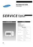
2.2.1.3
Facility Power Requirements
For proper redundancy, the facility must have two independent power sources. That
is, circuit breakers must be connected either to separate power company utility feeds
or to an uninterruptible power system (UPS). For power redundancy, the power
cords must not be connected to the same facility power source.
If the computer equipment is subjected to repeated power interruptions and
fluctuations, it is susceptible to a component failure rate that is higher than it would
be with a stable power source.
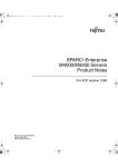
The M3000 server has the following basic connection configurations:
■
Power cords with a redundant PSU connection (FIGURE 2-1)
■
Power cords with a dual-power feed connection (FIGURE 2-2)
To connect the power cords in a redundant PSU connection to the same AC power
supply, connect each power cord independently to its own outlet.
2-4
SPARC Enterprise M3000 Server Installation Guide • March 2012
FIGURE 2-1
Power Cords With a Redundant PSU Connection
PSU#1 PSU#0
AC power supply
CB
CB
CB: Circuit breaker
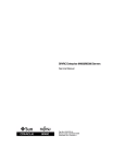
For a dual-power feed connection, connect each power cord separately to each AC
power supply system.
FIGURE 2-2
Power Cords With a Dual-Power Feed Connection
PSU#1 PSU#0
AC power supply
CB
CB: Circuit breaker
CB
Chapter 2
Preparing to Install the Server
2-5
2.2.1.4
Grounding
The M3000 server is shipped with two grounded type (three-wire type) power cords.
Always connect the power cords to grounded power outlets. Contact the facilities
manager or a qualified electrician to determine what type of power is supplied to
your building.
2.3
Requirements for Server Installation
The following items and information are required for installing the server. Prepare
them before installation.
■
Screwdriver, Phillips No. 2
Used for mounting the server on the rack
■
Antistatic wrist strap
Used to prevent static electricity from the human body from damaging the server
■
Antistatic mat
■
Ethernet cable of category 5 or higher
■
Administration console
Obtain one of the following from the customer:
■
ASCII terminal
■
Workstation
■
Terminal server (or a patch panel connected to a terminal server)
■
Personal computer (PC)
■
XSCF unit configuration information (IP address, subnet mask, default gateway,
etc.)
■
Domain configuration information (IP address, subnet mask, default gateway,
etc.)
■
Circuit tester
Used to check the input power voltage
2-6
SPARC Enterprise M3000 Server Installation Guide • March 2012
CHAPTER
3
Installing the Server
This chapter explains how to install the server. It contains the following sections:
■
Section 3.1, “Checking Components” on page 3-1
■
Section 3.2, “Mounting the Server in the Equipment Rack” on page 3-2
■
Section 3.3, “Connecting Cables” on page 3-2
■
Section 3.4, “Setting and Checking the Required Information for the Server” on
page 3-6
■
Section 3.5, “Powering On the Server” on page 3-10
■
Section 3.6, “Connecting Additional Peripheral Devices” on page 3-13
Caution – Extend only one server at a time out of the equipment rack to prevent the
rack from becoming unbalanced. The stabilizer or a Quake-Resistant Options Kit
must be deployed every time a server is pulled out of the rack.
3.1
Checking Components
This section explains how to check the M3000 server components.
1. Check the delivered items against the list of attachment that came with the server.
Note – If any optional item, such as additional memory or a PCI Express (PCIe)
card, is shipped separately, do not install it until normal operation of the server is
confirmed.
3-1
2. Check for a model name and configuration on the product test record.
If any of the items on the list of attachment or the product test record are missing,
incorrect, or damaged, contact your sales representative.
3.2
Mounting the Server in the Equipment
Rack
The M3000 server is mounted in the equipment rack for use. For the mounting
procedure, refer to the SPARC Enterprise Equipment Rack Mounting Guide.
Caution – Do not grab the handles on the front of the server to lift the server. The
front handles should be used only to insert the server into or pull it out from the
equipment rack. The handles are not designed to support the weight of the server.
3.3
Connecting Cables
This section explains how to connect power cords and the administration console.
3.3.1
Connecting Power Cords
This server is shipped with a grounded type (three-wire type) of power cord.
Always connect the power cords into grounded power outlets.
Caution – The server is designed to work with power systems having a grounded
neutral conductor. Do not connect the equipment into any other type of power
system. Contact the facilities manager or a qualified electrician to determine what
type of power is supplied to your building.
1. An electrician on site must confirm that the input power source satisfies the
electrical power requirements.
For the power requirements, refer to the SPARC Enterprise M3000 Server Site Planning
Guide.
3-2
SPARC Enterprise M3000 Server Installation Guide • March 2012
2. Make sure that each power cord is connected to the power supply unit and
secured with a cord clamp.
Do not connect the power source yet.
3. Arrange the layout of all cables outside the server, and secure them at the
specified locations to prevent them from being damaged.
4. Make sure that the AC power source circuit breaker is in the OFF position, and
then connect the power cords to the AC power source.
For redundancy in case of a power source failure, PSU#0 and PSU#1 must be
powered from separate sources. For the form of connection of the power cords, refer
to Section 2.2.1.3, “Facility Power Requirements” on page 2-4.
3.3.2
Connecting a UPS
An uninterruptible power supply (UPS) is used to provide a stable supply of power
to the system in the event of a power failure or an extensive power interruption. A
UPC port on the rear panel of the server can be connected to the UPC interface on
the UPS so that emergency shutdown processing can be executed safely.
If a UPS is procured, the UPS must have a separate power supply system. Connect
PSU#0 and PSU#1 independently to the systems for AC power supply. (See
FIGURE 3-1.)
In a connection with 1+1 redundancy, a UPS cable is connected to the UPC 0 port on
the server.
In a dual power feed connection, UPS cables are connected to the UPC0 port and
UPC1 port.
Note – The UPC1 port cannot be used for a connection with 1+1 redundancy. For
the UPC port interface specifications, refer to the SPARC Enterprise M3000 Server
Service Manual.
Chapter 3
Installing the Server
3-3
FIGURE 3-1
UPS Connections With a Dual-Power Feed Connection
PSU#1 PSU#0
UPC1
UPC0
UPS cable
CB
UPS#0
AC#0
CB
UPS#1
AC#1
CB: Circuit breaker
3.3.3
Connecting the Administration Console
The server is set up and statuses are displayed from the XSCF Shell through the
serial port on the XSCF unit. To connect the administration console with the serial
port, use the RS-232C cable (serial cable) supplied with the server. Also, the XSCF
Shell and the domain console (OS console) can be used with a terminal connected to
the serial port.
Note – The XSCF board is secured on the motherboard unit (MBU) in the M3000
server. In this document, the XSCF board in the M3000 server is called the XSCF
unit.
You can use any of the following devices with a DB-9 serial port as the
administration console:
3-4
■
ASCII terminal
■
Workstation
■
Terminal server (or a patch panel connected to a terminal server)
■
Personal computer
SPARC Enterprise M3000 Server Installation Guide • March 2012
Note – It is possible to connect it to a LAN port via telnet or SSH access. The LAN
port has a Class B private address value, but it will not send out a packet by itself
until configured.
Note – The modular connector (RCI connector) is not for use with a TNV circuit
connection. See Item 1 in FIGURE 3-2.
1. Confirm that the following settings have been made for software on the
administration console.
TABLE 3-1
Terminal Software Setting Values
Setting Item
Value
Baud rate
9600
Data length
8 bits
Parity
None
STOP bit
1 bit
Flow control
None
Delay
Other than 0
2. Prepare the serial cable.
The serial cable is supplied with the server.
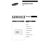
3. Connect the management console to the serial port on the rear panel (Item 3 in
FIGURE 3-2).
Note – Be careful not to connect a LAN cable to the serial port.
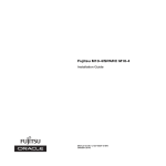
FIGURE 3-2 shows the locations of the external interface port such as serial port and
LAN ports on the rear panel.
Chapter 3
Installing the Server
3-5
FIGURE 3-2
Ports on the Rear Panel
1
2
12
Location Number
Port
1
RCI port*
2
USB port (for XSCF)
3
Serial port
4
LAN1 port (for XSCF)
5
LAN0 port (for XSCF)
6
UPC1 port
7
UPC0 port
8
Gigabit Ethernet (GbE) port 0 (for OS)
9
Gigabit Ethernet (GbE) port 1 (for OS)
10
Gigabit Ethernet (GbE) port 2 (for OS)
11
Gigabit Ethernet (GbE) port 3 (for OS)
12
Serial Attached SCSI (SAS) port
3
11
10
4
9
5
8
6
7
* : For information on whether the RCI function is supported for your server, see the SPARC Enterprise
M3000/M4000/M5000/M8000/M9000 Servers Product Notes.
3.4
Setting and Checking the Required
Information for the Server
Before you turn on the power to the server, the XSCF must be in its initial
configuration.
3-6
SPARC Enterprise M3000 Server Installation Guide • March 2012
Set and check the information required for the server, as described in this section.
Note – Use the administration console that has been connected as described in
Section 3.3.3, “Connecting the Administration Console” on page 3-4 for XSCF Shell
operations.
3.4.1
■
Section 3.4.1, “Logging in to the XSCF Shell” on page 3-7
■
Section 3.4.2, “Initializing the XSCF Unit” on page 3-9
Logging in to the XSCF Shell
To initialize the XSCF settings, use the XSCF default user account. Until the user’s
accounts for the user environment are registered, log in with the default user
account according to the authentication method. The privileges of the default user
are useradm and platadm.
Log in to the XSCF Shell with this procedure:
1. Set the key in the operator panel to the Service position.
The key for the operator panel is supplied with the server.
The Service position is indicated by the wrench symbol. The Locked position is
indicated by the lock symbol.
FIGURE 3-3
Mode Switch on the Operator Panel
Locked
Service
For details on the operator panel, refer to Section A.2, “Operator Panel Overview”
on page A-5.
Chapter 3
Installing the Server
3-7
2. Turn the AC power source circuit breaker to ON.
The server starts the XSCF initialization. That can take 5 minutes.
Note – If the power supply is interrupted as a result of disconnecting the power
cord or using the circuit breaker on the power distribution panel, wait at least 30
seconds before turning on the server again.
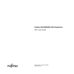
3. Check the LEDs of the XSCF unit.
FIGURE 3-4 shows the locations of the LEDs on the rear panel of the XSCF unit.
The CHECK LED (1) of the XSCF unit is turned on almost immediately after the AC
power supply system is turned on. The READY LED (2) of the XSCF unit flashes
during XSCF initialization and stays on when the initialization has been completed.
FIGURE 3-4
LEDs on the XSCF Unit
1
2
Location Number
LED Name
1
CHECK LED
2
READY LED
4. Watch the administration console for error messages as the XSCF Unit powers on.
For details on troubleshooting during installation work, refer to Appendix B.
5. Confirm that the XSCF STANDBY LED (green) on the operator panel is lit.
6. When the login prompt appears, type default as the login name.
login: default
3-8
SPARC Enterprise M3000 Server Installation Guide • March 2012
7. When a message prompting a mode switch operation appears, set the mode switch
on the operator panel as described below.
a. Set the mode switch on the operator panel to Locked, and press the Enter key.
Change the panel mode switch to Locked and press return...
b. Keep it in that state for at least 5 seconds.
Leave it in that position for at least 5 seconds.
c. Return the mode switch to Service, and press the Enter key.
Change the panel mode switch to Service, and press return...
Note – If the mode switch operation is not performed within one minute, the login
certification will expire.
8. Confirm that the XSCF Shell prompt is displayed on the administration console.
XSCF>
3.4.2
Initializing the XSCF Unit
You must make various settings to use the full XSCF functionality. This section
explains how to make the required settings for installation only.
1. Make only the required settings.
For details on the setting procedure, refer to the SPARC Enterprise
M3000/M4000/M5000/M8000/M9000 Servers XSCF User’s Guide.
The following settings are required:
■
Registration of an XSCF user account and password and user privileges (adduser,
password, setprivileges)
■
User account of a field engineer (FE) (for maintenance)
■
Date and time settings (setdate, settimezone)
■
Confirmation of the XSCF host public key (showssh)
■
SSH/telnet settings (setssh, settelnet)
■
Network interface, routing, and DNS-related settings
(setnetwork, setroute, setnameserver, etc.) (Note 1)
Chapter 3
Installing the Server
3-9
■
Domain to Service Processor Communications Protocol (DSCP) configuration
(setdscp) (Note 2)
■
Altitude setting (setaltitude) (Note 2)
■
Dual power feed option setting (setdualpowerfeed) (Note 3)
Note – (1) To apply the settings, the XSCF unit must be reset with the
applynetwork and rebootxscf commands.
Note – (2) To apply the settings, the XSCF unit must be reset with the rebootxscf
command.
Note – (3) To apply changes made with the setdualpowerfeed command, power
to the server must be completely disconnected and then reconnected (all power
cords must be disconnected and then reconnected). Wait at least 30 seconds before
reconnecting the power cords to the server.
2. Log in to the XSCF Shell with the user account and password that were set in Step
1.
For details on how to log in to a user account, refer to the SPARC Enterprise
M3000/M4000/M5000/M8000/M9000 Servers XSCF User’s Guide.
3.5
Powering On the Server
This section explains how to power on the server for the first time.
1. Set the key on the operator panel to the Service position.
2. From the XSCF Shell, type:
XSCF> console -d 0
Connect to DomainID 0?[y|n] :y
3. Confirm that the XSCF STANDBY LED (green) on the operator panel is lit.
4. Press the Power button on the operator panel to power on the server.
The server starts and begins a self-diagnosis.
Watch the administration console for error messages during this boot process. For
details on troubleshooting during installation, refer to Appendix B.
3-10
SPARC Enterprise M3000 Server Installation Guide • March 2012
5. Confirm that the POWER LED (green) on the operator panel is lit.
6. Confirm that “ok” is displayed on the domain console.
7. Check the LED for each component.
For the description of LEDs for each component and its function, refer to the SPARC
Enterprise M3000 Server Service Manual.
8. Press the Enter, "#" (default escape character), and "." (period) keys.
This key combination switches you from the domain console to the XSCF console.
9. From the XSCF Shell, execute the fmdump command or showlogs command, and
confirm that no errors are found.
For details, refer to Section B.3.4, “Using the fmdump Command” on page B-8 and
Section B.3.2, “Using the showlogs Command” on page B-7.
10. Connect the system control network to a LAN port on the XSCF unit with an
Ethernet cable.
The system control network has one or more administrative consoles used to
monitor the network. This connection will replace the temporary connection made
between the administration console and the serial port on the XSCF unit. For an
outline of the network connection, refer to FIGURE 4-1.
Note – The LAN ports on the XSCF unit conform to IEEE 802.3i and IEEE 802.3u.
However, only the auto negotiation mode can be used for negotiation. The fixed
mode cannot be used.
3.5.1
Verifying the Configuration
Verify the hardware configuration by following this procedure on the administration
console connected to the system control network.
1. Log in to the server, and access the XSCF Shell.
For details, refer to the SPARC Enterprise M3000/M4000/M5000/M8000/M9000 Servers
XSCF User’s Guide.
2. From the XSCF Shell, type the showhardconf command.
All the components installed in the server and their statuses are displayed. For
details on how to use the showhardconf command and an output example, refer to
Section B.3.1, “Using the showhardconf Command” on page B-4.
3. Confirm that no asterisk (*) is displayed in front of any FRUs.
Chapter 3
Installing the Server
3-11
4. From the XSCF Shell, type the showhardconf command with the -u option.
5. Check the number of FRUs mounted on the server against the product test record.
For an output example of showhardconf -u, refer to Section B.3.1.1,
“showhardconf -u Command” on page B-6.
6. From the XSCF Shell, type the console command with the -d 0 option.
This switches you from the XSCF console back to the domain console (OS console)
and displays the ok prompt.
XSCF> console -d 0
Connect to DomainID 0?[y|n] :y
ok
7. At the ok prompt, type the probe-scsi-all command.
8. Confirm that the CD-RW/DVD-RW drive unit and hard disk drive installed in the
server are recognized.
9. At the ok prompt, type the show-devs command.
10. Confirm that each installed PCIe card is recognized.
11. Compare the configuration shown by showhardconf -u, probe-scsi-all, and
show-devs with the product test record.
If the configuration is incorrect, contact your sales representative.
12. Press the Enter, "#" (default escape character), and "." (period) keys.
This key combination switches you from the domain console (OS console) back to
the XSCF console.
3.5.2
Checking the Dual-Power Feed
For a system using the dual-power feed option, follow the procedure below to
confirm that the system can operate even if one power feed is stopped.
1. Confirm that the system is powered on by checking the output of the
showdomainstatus -a command from the XSCF Shell.
2. Switch off the AC power supply system on the PSU#0 side.
3. Confirm that the POWER LED on the operator panel is lit.
4. From the XSCF Shell, confirm a power failure by executing the showlogs event
command.
3-12
SPARC Enterprise M3000 Server Installation Guide • March 2012
5. Switch on the AC power supply system on the PSU#0 side (which was switched
off in Step 2).
6. From the XSCF Shell, confirm a power recovery by executing the showlogs
event command.
7. Confirm that the AC LED and DC LED on PSU#0 are lit.
8. From the XSCF Shell, confirm a Power Status is On by executing the
showhardconf command.
9. Switch off the AC power supply system on the PSU#1 side.
10. Confirm that the POWER LED on the operator panel is lit.
11. From the XSCF Shell, confirm a power failure by executing the showlogs event
command.
12. Switch on the AC power supply system on the PSU#1 side (which was switched
off in Step 9).
13. From the XSCF Shell, confirm a power recovery by executing the showlogs
event command.
3.6
Connecting Additional Peripheral
Devices
For details on how to add optional devices, such as additional memory or an
additional PCIe card, refer to the SPARC Enterprise M3000 Server Service Manual.
To add an additional storage device or other peripheral device, refer to the manual
supplied with the device.
Chapter 3
Installing the Server
3-13
3-14
SPARC Enterprise M3000 Server Installation Guide • March 2012
CHAPTER
4
Connecting the Domain to the
Network
This chapter explains how to establish a network for the M3000 server. It contains
the following sections:
4.1
■
Section 4.1, “Network Configuration Overview” on page 4-1
■
Section 4.2, “Connecting to the Network” on page 4-2
■
Section 4.3, “Verifying the Network Connection” on page 4-3
■
Section 4.4, “Starting the Oracle Solaris Operating System” on page 4-3
■
Section 4.5, “Verifying Operation by Running Oracle VTS” on page 4-4
Network Configuration Overview
This section provides an overview of the network connections of the M3000 server.
You can connect the M3000 server to the network through one of the four onboard
Gigabit Ethernet (GbE) ports.
Alternatively, you can mount a LAN card prepared by the customer in a PCIe slot to
connect the server to the network. FIGURE 4-1 shows a user network, which is for
user access to the domain.
Note – To isolate the domain from the network, skip the steps in Section 4.2,
“Connecting to the Network” on page 4-2 and Section 4.3, “Verifying the Network
Connection” on page 4-3.
4-1
FIGURE 4-1
Outline of Network Connections
Administration
Firewall
console
Switch
Switch
System control network
User network
Switch
4.2
Connecting to the Network
This section explains how to connect the M3000 server to the network.
The customer must supply the hubs, switches, and cables used for network
connections.
1. Connect one end of an Ethernet cable to a GbE port (for the OS) on the rear panel.
You can connect the Ethernet cable to a GbE port (for the OS) on the rear panel or to
the LAN port on a LAN card mounted in a PCIe slot.
2. Connect the other end of the Ethernet cable to the customer’s network
environment.
4-2
SPARC Enterprise M3000 Server Installation Guide • March 2012
4.3
Verifying the Network Connection
This section explains how to verify the user network connection made as described
in Section 4.2, “Connecting to the Network” on page 4-2.
1. Set the mode switch on the operator panel to the Service position.
2. Press the Power button on the operator panel to power on the server.
3. Confirm the status of the LINK SPEED LED (see FIGURE 4-2) of the connected port
as described in Section 4.2, “Connecting to the Network” on page 4-2.
■
When amber is lit, the communication speed of LAN port is 1G bps.
■
When green is lit, the communication speed of LAN port is 100M bps.
■
When it is off, the communication speed of LAN port is 10M bps.
FIGURE 4-2
Location of LINK SPEED LED
LINK SPEED LED
GbE port on the rear panel
4.4
Starting the Oracle Solaris Operating
System
Start the Oracle Solaris Operating System, as described in this section.
When performing this operation after the operations in Section 4.3, “Verifying the
Network Connection” on page 4-3, start from Step 5.
Note – Oracle Solaris OS is pre-installed in the hard disk drive (HDD) of slot#0.
When you start Oracle Solaris OS from this HDD, a message appears to configure
the Oracle Solaris OS in line with the environment in use.
1. Set the mode switch on the operator panel to the Service position.
Chapter 4
Connecting the Domain to the Network
4-3
2. Press the Power button on the operator panel to power on the server.
3. From the administration console, log in to the XSCF Shell.
4. From the XSCF Shell, type the console command.
This switches you from the XSCF console to the domain console (OS console)
XSCF> console -d 0
Connect to DomainID 0?[y|n] :y
ok
5. At the ok prompt of the domain console (OS console), type the boot command.
ok
boot
6. Watch the domain console (OS console) for error messages during this boot
process.
If an error message is displayed, refer to Appendix B.
7. At the login prompt, log in by using the root privilege.
4.5
Verifying Operation by Running Oracle
VTS
Oracle VTS is a diagnosis tool for verifying hardware operations and device
connection statuses.
This section explains how to verify operation by using Oracle VTS.
Note – Oracle VTS is installed in the Oracle Solaris OS pre-installed version. For
details, see the Oracle VTS User’s Guide.
This section explains how to run the Oracle VTS 7.0ps9 software from the TTY user
interface.
1. Type the startsunvts command to start the Oracle VTS software.
# cd /usr/sunvts/bin
# ./startsunvts -t
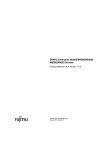
The Oracle VTS TTY main window appears.
4-4
SPARC Enterprise M3000 Server Installation Guide • March 2012
FIGURE 4-3
Oracle VTS TTY Main Window
1
2
3
Number
Window Item
1
Control panel
2
Test_Groups panel
3
Status panel
TABLE 4-1
Description of the TTY Keyboard
Key
Description of Operation
Tab key
Shifts the focus to another window. For example, when you press the
tab key on the Control panel, the focus (highlighted part) is shifted to
the Status panel, which is then framed by asterisks (*).
Arrow keys
Moves between options in the panel.
Return
Displays the menu.
This selects and applies an option or command on the menu.
Chapter 4
Connecting the Domain to the Network
4-5
TABLE 4-1
Description of the TTY Keyboard (Continued)
Key
Description of Operation
Spacebar
Checks or unchecks the check box of an option in the test panel.
[*]: Selected
[ ]: Not selected
Backspace key
Deletes text in a text field.
Escape
Discards a pop-up menu or window.
Control-F
Scrolls forward in a scrollable window.
Control-B
Scrolls backward in a scrollable window.
Control-X
Quits the TTY user interface but leaves the Oracle VTS kernel running.
Control-L
Refreshes the TTY window.
2. Select an item to be tested.
a. Use the tab key to move to the Test_Groups panel.
b. Use the arrow keys to select the item.
3. Run the test program.
a. Use the tab key to move to the Control panel.
b. Use the arrow keys to highlight start, and press the Enter key.
c. In the small window displayed, highlight start and press the Enter key again,
to start diagnosis.
d. Confirm that no Error is displayed in the Status panel or Message panel.
4. Stop the test program.
a. Use the tab key to move to the Control panel.
b. Use the arrow keys to highlight stop, and press the Enter key.
5. Check the test results.
When the test program is stopped, the number of test loops executed and the
number of errors are displayed.
Confirm that there is no error.
6. Press the Enter, "#" (default escape character), and "." (period) keys.
This key combination switches you from the domain console to the XSCF console.
7. Type the fmdump command or the showlogs error command at the XSCF Shell.
4-6
SPARC Enterprise M3000 Server Installation Guide • March 2012
8. Confirm that no errors are displayed in the XSCF console after using the fmdump
or the showlogs error commands.
If an error is displayed, see Section B.3, “Using Status Commands” on page B-3.
9. Type the poweroff -d 0 command at the XSCF Shell to power off the system.
XSCF> poweroff -d 0
10. Set the mode switch on the operator panel back to Locked, and hand the key to
the system administrator.
Chapter 4
Connecting the Domain to the Network
4-7
4-8
SPARC Enterprise M3000 Server Installation Guide • March 2012
APPENDIX
A
Server Views
Appendix A provides views of the server. It contains the following sections:
A.1
■
Section A.1, “The Server Views” on page A-1
■
Section A.2, “Operator Panel Overview” on page A-5
The Server Views
FIGURE A-1 shows a front view of the server.
FIGURE A-1
Server (Front View)
4
3
1
2
5
6
7
Location Number
Name
Abbreviation
1
Fan unit
FAN_A#0
2
Fan unit
FAN_A#1
3
Operator panel
OPNL
8
A-1
Location Number
Name
Abbreviation
4
CD-RW/DVD-RW drive unit
DVDU
5
Hard disk drive
HDD#0
6
Hard disk drive
HDD#1
7
Hard disk drive
HDD#2
8
Hard disk drive
HDD#3
FIGURE A-2 shows a rear view of the server.
FIGURE A-2
Server (Rear View)
1
2
3
4
5
6
7
Location Number
Name
Abbreviation
1
Power supply unit
PSU#1
2
Power supply unit
PSU#0
3
PCIe slot
PCI#3
4
PCIe slot
PCI#2
5
PCIe slot
PCI#1
6
PCIe slot
PCI#0
7
Rear panel
A-2
SPARC Enterprise M3000 Server Installation Guide • March 2012
FIGURE A-3 shows a top view of component mounting locations in the server.
FIGURE A-3
Server (Top View)
8
9
10
11
1-a
12
13
14
1
15
2
16
3
17
4
5
1-b
6
7
1-c
Location Number
Name
Abbreviation
1
Motherboard unit
**
1-a
XSCF unit *
1-b
CPU * †
1-c
DC-DC converter * ‡
Appendix A
Server Views
A-3
Location Number
Name
Abbreviation
2
Memory slot
DIMM (MEM#00A)
3
Memory slot
DIMM (MEM#00B)
4
Memory slot
DIMM (MEM#01A)
5
Memory slot
DIMM (MEM#01B)
6
Fan unit
FAN_A#0
7
Fan unit
FAN_A#1
8
PCIe slot
PCI#0
9
PCIe slot
PCI#1
10
PCIe slot
PCI#2
11
PCIe slot
PCI#3
12
Power supply unit
PSU#0
13
Power supply unit
PSU#1
14
Memory slot
DIMM (MEM#02A)
15
Memory slot
DIMM (MEM#02B)
16
Memory slot
DIMM (MEM#03A)
17
Memory slot
DIMM (MEM#03B)
* These components are fixed to the motherboard unit.
† There are four types of CPU.
‡ DC-DC converters on MBU_A_5 and MBU_A_6 have different shapes.
** The abbreviation of the motherboard unit varies according to the type of CPU mounted.
TABLE A-1 lists the types of motherboard unit, with corresponding CPU.
TABLE A-1
A-4
Motherboard Unit and Corresponding CPU
Motherboard Unit
CPU (Frequency/Cores)
MBU_A
SPARC64 VII ( 2.52 GHz / 4core )
MBU_A_2
SPARC64 VII ( 2.52 GHz / 2core )
MBU_A_3
SPARC64 VII ( 2.75 GHz / 4core )
MBU_A_4
SPARC64 VII ( 2.75 GHz / 2core )
MBU_A_5
SPARC64 VII+ ( 2.86 GHz / 4core )
MBU_A_6
SPARC64 VII+ ( 2.86 GHz / 2core )
SPARC Enterprise M3000 Server Installation Guide • March 2012
A.2
Operator Panel Overview
If no network connection is available, the operator panel is used to start or stop the
system. The operator panel has three LED status indicators, a power button, and a
mode switch (key switch). The panel is located at the center on the front of the
server.
While the system is running, the Power LED and the XSCF STANDBY LED (green)
should be on, and the CHECK LED (orange) should not be on. If the CHECK LED is
on, search the system logs to determine what is wrong.
The three LED status indicators on the operator panel show the following:
■
General system status
■
System problem warning
■
System fault location
FIGURE A-4 shows the operator panel of the server.
Appendix A
Server Views
A-5
FIGURE A-4
Operator Panel Location
1
2
3
4
5
Location Number
Component
1
POWER LED
2
XSCF STANDBY LED
3
CHECK LED
4
Power button
5
Mode switch (key switch)
During startup, the firmware toggles the front panel LEDs on and off to confirm that
each one is working correctly. After that, the front panel LEDs operate as described
in TABLE A-2.
A-6
SPARC Enterprise M3000 Server Installation Guide • March 2012
TABLE A-2
Icon
XSCF
LEDs on the Operator Panel
Name
Color
Description
POWER
LED
Green
Indicates the server power status.
• On: The power to the server (a domain) is on.
• Off: The power to the server is off.
• Blinking: The server is powered off.
XSCF
STANDBY
LED
Green
Indicates the XSCF unit status.
• On: XSCF unit is functioning normally.
• Off: Input power source is off or is just after
turned on, and XSCF unit is stopped.
• Blinking: System initialization is in progress after
power was turned on.
CHECK
LED
Amber
Indicates that the server has detected an error. This is
sometimes called a locator.
• On: An error that hinders startup was detected.
• Off: Normal, or power is not being supplied.
• Blinking: Indicates that the unit is a maintenance
target.
The switches on the operator panel include the mode switch for setting the operation
mode and the power button for turning on and off the server.
The information about operator panel switches is described in TABLE A-3.
TABLE A-3
Switch
Switches on the Operator Panel
Name
Description of Function
Mode Switch
(key switch)
This switch is used to set the operation mode for the server.
Insert the special key that is under the customer's control, to
switch between modes.
Locked
Normal operation mode
• The system can be powered on with the power button, but it
cannot be powered off with the power button.
• The key can be pulled out at this key position.
Service
Mode for maintenance
• The system can be powered on and off with the power
button.
• The key cannot be pulled out at this key position.
• To stop and maintain the server, set the mode to Service.
Appendix A
Server Views
A-7
TABLE A-3
Switch
Switches on the Operator Panel (Continued)
Name
Description of Function
Power button
This button is used to turn on or turn off the power to the
server (a domain).
Power on and power off are controlled by pressing this button
in different patterns, as described below.
Holding down the
button for a short
time
(less than 4 seconds)
Regardless of the mode switch setting, the server is powered
on.
If set in the XSCF, facility (air conditioners) power-on and
warm-up processing is skipped. *
Holding down the
button for a long
time in Service mode
(4 seconds or longer)
• If power to the server is on, OS shutdown processing is
executed for a domain before the system is powered off.
• If the server is being powered on, the power-on processing
is cancelled, and the server is powered off.
• If the server is being powered off, the operation of the
power button is ignored, and the power-off processing is
continued.
* In normal operation, the server is powered on only when the computer room environmental conditions satisfy the specified values.
Then, the server remains in the reset state until the operating system is booted.
TABLE A-4
Function of the Mode Switch
Function
Mode Switch
Locked
Service
Inhibition of Break Signal Reception
Enabled. Reception of the
Break signal can be enabled or
disabled for each domain
using setdomainmode.
Disabled
Power On/Off by power switch
Only Power On is enabled.
Enabled
A-8
SPARC Enterprise M3000 Server Installation Guide • March 2012
APPENDIX
B
Troubleshooting
This appendix describes the actions to take for problems that occur during
installation of the SPARC Enterprise M3000 server from Oracle and Fujitsu.
B.1
■
Section B.1, “Corrective Actions to Common Problems” on page B-1
■
Section B.2, “Emergency Power Off” on page B-2
■
Section B.3, “Using Status Commands” on page B-3
Corrective Actions to Common Problems
This section describes problems related to installation and their solutions.
TABLE B-1
Common Installation Problems
Problem
Solution
No power to the server
• Make sure that the power cords are firmly connected to
both the power supply units of the server and the input
power source.
• Make sure that the power supply units of the server are
firmly mounted.
• If a UPS is connected, make sure that the server and the
UPS are properly connected, the UPS is powered on, and
the UPS LEDs indicate the normal state.
• Make sure that the distribution panel of the equipment rack
is powered on.
B-1
Caution – Do not make any repairs to the system by yourself. Contact us (Oracle
and Fujitsu) and ensure that repair of the system will be performed by a certified
service engineer. When the authorized service personnel performs their work on
your system, they might need to log into the system with the domainadm privilege
for the administration of a specific domain, the platadm privilege for management of
the entire system, or the fieldeng privilege for the maintenance work. If our
engineer asks you to supply this permission, please take appropriate action to ensure
that the engineer can perform the required work.
The method of troubleshooting a problem that occurs on the system varies
depending on the problem and the system operating status. The following sections
explain troubleshooting by type of method.
TABLE B-2
Types of Troubleshooting Methods
Troubleshooting Method
Description
Check LEDs
The LEDs on the operator panel indicate any system or hardware error
detected during initial diagnosis or system operation. Additional LEDs are
provided on FRUs, such as a motherboard unit, PSU, and fan unit, so that
you can locate faulty components and identify error states.
For details on LED types and their error indications, refer to the SPARC
Enterprise M3000 Server Service Manual.
Check log files
You can check the system log file (/var/adm/messages) for messages on
errors detected by the OS and on any panic that occurred.
For details, refer to the SPARC Enterprise M3000 Server Service Manual.
Check using the XSCF Shell You can use the XSCF Shell to find details of an error state, the device
status history, and other status information.
For details, refer to Section B.3, “Using Status Commands” on page B-3, or
the SPARC Enterprise M3000/M4000/M5000/M8000/M9000 Servers XSCF
User’s Guide.
B.2
Emergency Power Off
This section explains how to power off in an emergency.
Caution – In an emergency (such as smoke or flames coming from the server),
immediately stop using the server and turn off the power supply. Regardless of the
type of business, give top priority to fire prevention measures.
B-2
SPARC Enterprise M3000 Server Installation Guide • March 2012
1. Press the power switch for more than 4 seconds to turn off the power to the
server.
2. Remove the power cord clamp and disconnect the cable (see FIGURE B-1).
FIGURE B-1
B.3
Power-off Method
Using Status Commands
The following commands are described in detail in this section:
■
“Using the showhardconf Command” on page 4
■
“Using the showlogs Command” on page 7
■
“Using the showstatus Command” on page 7
■
“Using the fmdump Command” on page 8
Appendix B
Troubleshooting
B-3
B.3.1
Using the showhardconf Command
The showhardconf command displays the following information about each FRU:
■
Current configuration and status
■
Number of installed FRUs
■
Domain information
■
Name properties of PCIe cards
When you use the showhardconf command to show the FRU configuration and
status information and the domain information, it displays any of the status
described below. Beside a unit failed or degraded, placed an asterisk (*) indicating
the locating fault.
B-4
■
Faulted: The component is faulty and is not operating.
■
Degraded: The component is operating. However, either an error has been
detected or the component is faulty. As a result, the component might be
operating with reduced functionality or performance.
■
Deconfigured: As a result of another component's faulted or degraded status, the
component is not operating. (The component itself is not faulted or degraded.).
■
Maintenance: The component is under maintenance. A deletefru (8),
replacefru (8), or addfru (8) operation is currently underway.
■
Normal: Operating normally.
SPARC Enterprise M3000 Server Installation Guide • March 2012
Example of showhardconf command execution
XSCF> showhardconf
SPARC Enterprise M3000;
+ Serial:IKK0813023; Operator_Panel_Switch:Locked;
+ Power_Supply_System:Single; SCF-ID:XSCF#0;
+ System_Power:On; System_Phase:Cabinet Power On;
Domain#0 Domain_Status:OpenBoot Execution Completed;
MBU_A Status:Normal; Ver:0501h; Serial:PP104905FD ;
+ FRU-Part-Number:CA07082-D071 A3
/542-0420-01 ;
+ CPU Status:Normal;
+ Freq:2.860 GHz; Type:48;
+ Core:4; Strand:2;
+ Memory_Size:8 GB;
MEM#0A Status:Normal;
+ Code:ce0000000000000001M3 93T2950EZA-CE6 4145-473b3c23;
+ Type:1A; Size:1 GB;
MEM#0B Status:Normal;
+ Code:7f7ffe00000000004aEBE10RD4AJFA-5C-E 3020-223b2918;
+ Type:1A; Size:1 GB;
MEM#1A Status:Normal;
+ Code:7f7ffe00000000004aEBE10RD4AJFA-5C-E 3020-223b28af;
+ Type:1A; Size:1 GB;
MEM#1B Status:Normal;
+ Code:7f7ffe00000000004aEBE10RD4AJFA-5C-E 3020-223b28af;
+ Type:1A; Size:1 GB;
MEM#2A Status:Normal;
+ Code:7f7ffe00000000004aEBE10RD4AJFA-5C-E 3020-223b283e;
+ Type:1A; Size:1 GB;
MEM#2B Status:Normal;
+ Code:7f7ffe00000000004aEBE10RD4AJFA-5C-E 3020-223b28ab;
+ Type:1A; Size:1 GB;
MEM#3A Status:Normal;
+ Code:7f7ffe00000000004aEBE10RD4AJFA-5C-E 3020-223b2840;
+ Type:1A; Size:1 GB;
MEM#3B Status:Normal;
+ Code:7f7ffe00000000004aEBE10RD4AJFA-5C-E 3020-223b2830;
+ Type:1A; Size:1 GB;
Appendix B
Troubleshooting
B-5
Example of showhardconf output (continued)
PCI#0 Name_Property:fibre-channel; Card_Type:Other;
PCI#1 Name_Property:fibre-channel; Card_Type:Other;
PCI#2 Name_Property:pci; Card_Type:Other;
PCI#3 Name_Property:pci; Card_Type:Other;
OPNL Status:Normal; Ver:0101h; Serial:PP082202R8 ;
+ FRU-Part-Number:CA07082-D911 A1
/541-3306-01
PSU#0 Status:Normal; Serial:EA08260208;
+ FRU-Part-Number:CA01022-0720 03C /300-2193-03
+ Power_Status:On;
PSU#1 Status:Normal; Serial:EA08260210;
+ FRU-Part-Number:CA01022-0720 03C /300-2193-03
+ Power_Status:On;
FANBP_B Status:Normal; Ver:0101h; Serial:PP082704TD ;
+ FRU-Part-Number:CA20399-B12X 006AB/541-3304-02
FAN_A#0 Status:Normal;
FAN_A#1 Status:Normal;
XSCF>
B.3.1.1
;
;
;
;
showhardconf -u Command
The showhardconf command with the -u option displays the number of FRUs
installed in each unit. You can check the operating frequency of CPU module and the
capacity of memory.
Example of showhardconf -u command execution
XSCF> showhardconf -u
SPARC Enterprise M3000; Memory_Size:8 GB;
+-----------------------------------+------------+
|
FRU
| Quantity |
+-----------------------------------+------------+
| MBU_A
|
1
|
|
CPU
|
(
1)
|
|
Freq:2.860 GHz;
|
(
1)
|
|
MEM
|
4
|
|
Type:8B; Size:8 GB;
|
(
4)
|
| OPNL
|
1
|
| PSU
|
2
|
| FANBP_B
|
1
|
|
FAN_A
|
2
|
+-----------------------------------+------------+
XSCF>
B-6
SPARC Enterprise M3000 Server Installation Guide • March 2012
B.3.2
Using the showlogs Command
The showlogs command displays the contents of the specified log in order of
timestamp. The displayed contents begin from the oldest date. The showlogs
command displays the following logs:
■
Error log
■
Power log
■
Event log
■
Temperature and humidity record
■
Monitoring message log
■
Console message log
■
Panic message log
■
IPL message log
Example of showlogs output
XSCF> showlogs error
Date: Jun 17 13:46:31 JST 2008 Code: 60000000-cd01c701-0164010100000000
Status: Warning
Occurred: Jun 17 13:46:31.158 JST 2008
FRU: /OPNL,/FANBP_B
Msg: TWI access error
Date: Jun 17 13:41:46 JST 2008
Code: 80002080-7801c201-0130000000000000
Status: Alarm
Occurred: Jun 17 13:41:44.861 JST 2008
FRU: /MBU_A,*
Msg: Board control error (MBC link error)
Date: Jun 17 11:05:32 JST 2008
Code: 80000000-c3ff0000-0173000600000000
Status: Alarm
Occurred: Jun 17 11:05:32.522 JST 2008
FRU: /PSU#1
Msg: PSU shortage
XSCF>
B.3.3
Using the showstatus Command
The showstatus command displays information concerning a faulty or degraded
FRU and the FRU that is one layer above the faulty or degraded FRU in the server.
The displayed FRU information includes an asterisk (*), which indicates the location
of the problem, and any of the following states after "Status:":
■
Normal: The component is operating normally.
■
Faulted: The component is faulty and is not operating.
Appendix B
Troubleshooting
B-7
■
Degraded: The component is operating. However, either an error has been
detected or the component is faulty. As a result, the component might be
operating with reduced functionality or performance.
■
Deconfigured: As a result of another component's faulted or degraded status, the
component is not operating. (The component itself is not faulted or degraded.)
■
Maintenance: The component is under maintenance. A deletefru (8),
replacefru (8), or addfru (8) operation is currently underway.
Example of showstatus output
XSCF> showstatus
FANBP_B Status:Normal;
*
FAN_A#0 Status:Faulted;
XSCF>
B.3.4
Using the fmdump Command
The fmdump command displays the contents of any log files managed by the
module called Fault Manager.
This example assumes there is only one fault.
# fmdump
TIME UUID SUNW-MSG-ID
Nov 02 10:04:15.4911 0ee65618-2218-4997-c0dc-b5c410ed8ec2 SUN4-8000-0Y
B.3.4.1
fmdump -V Command
You can obtain information in more detail with the -V option, as shown in the
following example.
# fmdump -V -u 0ee65618-2218-4997-c0dc-b5c410ed8ec2
TIME
UUID
Nov 02 10:04:15.4911 0ee65618-2218-4997-c0dc-b5c410ed8ec2
100% fault.io.fire.asic
FRU: hc://product-id=SUNW,A70/motherboard=0
rsrc: hc:///motherboard=0/hostbridge=0/pciexrc=0
SUNW-MSG-ID
SUN4-8000-0Y
At least three lines of new output are delivered by the -V option:
■
B-8
The first line is a summary of the information that you have seen before in the
console message, including the timestamp, UUID, and message ID.
SPARC Enterprise M3000 Server Installation Guide • March 2012
B.3.4.2
■
The second line is a declaration of the certainty of the diagnosis. In this example,
there is a 100 percent probability that the failure is in the indicated ASIC. As
another example, if the diagnosis were to involve two components, you would see
two lines here with 50% on each line.
■
The "FRU" line declares the part that must be replaced to return the server to a
fully operational state.
■
The "rsrc" line identifies the component taken out of service as a result of this
fault.
fmdump -e Command
To obtain information on the error that caused a failure, use the -e option as shown
in the following example.
# fmdump -e
TIME
CLASS
Nov 02 10:04:14.3008 ereport.io.fire.jbc.mb_per
Appendix B
Troubleshooting
B-9
B-10
SPARC Enterprise M3000 Server Installation Guide • March 2012
APPENDIX
C
DC Power Supply Model
This appendix describes the requirements specific to the DC power supply model.
Contact your sales representative for the DC power supply model.
To use the DC power supply model, please make sure to read this information.
■
Section C.1, “Preparing Power Supply Equipment” on page C-1
This is equivalent to Section 2.2.1, “Preparing Power Supply Equipment” on
page 2-2. When using the DC power supply model, refer to the content described
in this appendix.
■
Section C.2, “The Server Views” on page C-6
This is equivalent to Section A.1, “The Server Views” on page A-1. When using
the DC power supply model, refer to the content described in this appendix.
■
Section C.3, “Showhardconf Command” on page C-7
This is equivalent to Section B.3.1, “Using the showhardconf Command” on
page B-4. When using the DC power supply model, refer to the content described
in this appendix.
Note – The content not mentioned in this appendix is common to the AC power
supply model and the DC power supply model. Refer to the description in each
chapter.
C.1
Preparing Power Supply Equipment
This section describes the electrical specifications, power cord specifications, facility
power requirements, and grounding of the DC power supply model.
C-1
Note – This is equivalent to Section 2.2.1, “Preparing Power Supply Equipment” on
page 2-2. When using the DC power supply model, refer to the content described in
this appendix.
Note – The DC power supply model must be installed in a restricted access location.
The restricted access location is an area intended for qualified or trained personnel
only, access to which is controlled by a locking mechanism. For example, a key or an
access card system.
C.1.1
Electrical Specifications
The values in the following table are the maximum power values for the server in its
maximum configuration. The actual values vary depending on the system
configuration.
TABLE C-1
Electrical Specifications
Item
Specifications
CPU: 2.75 GHz / CPU: 2.86 GHz
Input voltage
-48 Vdc
Number of power cords
2 (1 cord for each power supply unit)
Power cord length
5 m/16.4 ft
Redundancy
1 + 1 redundant configuration
current*
-60Vdc
10.52 A
8.50 A
Maximum power
consumption
505W
510 W
Heat dissipation
1,723.1 BTU/hr (1,818
KJ/hr)
1,740.2 BTU/hr (1,836
KJ/hr)
Rated
* In a redundant configuration, the rated current per cable is half the value shown in TABLE C-1.
C.1.2
Power Cord Specifications
TABLE C-2 lists the power cord specifications of the DC power supply model.
C-2
SPARC Enterprise M3000 Server Installation Guide • March 2012
TABLE C-2
FIGURE C-1
DC Power Cord Specifications
Item
Specification
Connector
294-0085-00100A of ELCON
Cable structure
Three AWG 14 wires
Cable length
5m
View of DC Power Cords
-48 Vdc to -60 Vdc (wire color: blue)
FG
RTN
RTN (wire color: black)
FG (wire color: green and yellow)
-48 Vdc to -60 Vdc
The DC power cord has a connector only for the server end. Therefore, a terminal
matching the DC power supply equipment will need to be attached to the DC power
supply end of the cord.
C.1.3
Facility Power Requirements
The power supply that can be used with the M3000 server is restricted to DC power
supply equipment that is separate from the AC power, or DC power supply
equipment that has double or reinforced insulation for high, dangerous voltages.
Always mount overcurrent protective devices between the DC power supply
equipment and the M3000 server. One overcurrent protective device is required for
each power supply line. The overcurrent protective devices must comply with the
following specifications:
■
Current rating: 30 A
■
Voltage rating: at least 65 Vdc
■
Operation type: Immediate shutdown type (however, overcurrent protective
devices should not operate against 1 ms rush currents with a peak current of
100 A)
■
Number of poles: 2 (-48 Vdc to -60 Vdc line and RTN line)
Appendix C
DC Power Supply Model
C-3
Note – Overcurrent protection devices must meet applicable national and local
electrical safety codes and be approved for the intended application.
The DC power supply model of the M3000 server has the following basic connection
configurations:
■
Power cords with a redundant PSU connection (FIGURE C-2)
■
Power cords with a dual-power feed connection (FIGURE C-3)
To connect the power cords in a redundant PSU configuration to the same DC power
supply, connect each power cord independently to its own outlet.
FIGURE C-2
Power Cords With a Redundant PSU Connection
PSU#1 PSU#0
Branch connection
-48 Vdc to -60 Vdc
RTN
-48 Vdc to -60 Vdc
Battery
Rectifier
CB
AC
CB
RTN
FG
FG
Ground point
Customer facilities
CB: Circuit breaker
To connect the power cords in a dual power feed configuration, connect each power
cord separately to each DC power supply equipment.
C-4
SPARC Enterprise M3000 Server Installation Guide • March 2012
FIGURE C-3
Power Cords With a Dual-Power Feed Connection
PSU#1 PSU#0
Branch connection
-48 Vdc to -60 Vdc
RTN
FG
Battery
Rectifier
CB
AC
Ground point
-48 Vdc to -60 Vdc
CB
RTN
AC
FG
Ground point
Customer facilities
C.1.4
CB: Circuit breaker
Grounding
The DC power supply model of the M3000 server is shipped with two DC power
cords. Since these DC power cords have a connector only for the server end, a
terminal matching the DC power supply equipment will need to be attached to the
DC power supply end of the cord. Moreover, the power supply equipment must be
correctly grounded. Confirm that the grounding prong is connected to the positive
bus on the battery box.
The grounding resistance must not be greater than 10Ω. The grounding method
varies by the building where you install the server. Make sure that the facility
administrator or a qualified electrician verifies the grounding method for the
building and performs the grounding work.
Appendix C
DC Power Supply Model
C-5
C.2
The Server Views
This section describes the names of parts mounted on the DC power supply model.
Note – This is equivalent to Section A.1, “The Server Views” on page A-1. When
using the DC power supply model, refer to the content described in this appendix.
FIGURE C-4 shows a front view of the DC power supply model.
FIGURE C-4
Server (Front View) : DC Power Supply Model
4
3
1
2
5
6
7
Location Number
Name
Abbreviation
1
Fan unit
FAN_A#0
2
Fan unit
FAN_A#1
3
Operator panel
OPNL
4
CD-RW/DVD-RW drive unit
DVDU
5
Hard disk drive
HDD#0
6
Hard disk drive
HDD#1
7
Hard disk drive
HDD#2
8
Hard disk drive
HDD#3
8
FIGURE C-5 shows a rear view of the DC power supply model.
C-6
SPARC Enterprise M3000 Server Installation Guide • March 2012
FIGURE C-5
Server (Rear View) : DC Power Supply Model
1
2
3
4
5
6
7
Location Number
Name
Abbreviation
1
Power supply unit
PSU#1
2
Power supply unit
PSU#0
3
PCIe slot
PCI#3
4
PCIe slot
PCI#2
5
PCIe slot
PCI#1
6
PCIe slot
PCI#0
7
Rear panel
C.3
Showhardconf Command
This section describes the showhardconf command on the DC power supply
model.
Note – This is equivalent to Section B.3.1, “Using the showhardconf Command” on
page B-4. When using the DC power supply model, refer to the content described in
this appendix.
The showhardconf command displays the following information about each FRU:
■
Current configuration and status
■
Number of installed FRUs
■
Domain information
Appendix C
DC Power Supply Model
C-7
■
Name properties of PCIe cards
When you use the showhardconf command to show the FRU configuration and
status information and the domain information, it displays any of the status
described below. Beside a unit failed or degraded, placed an asterisk (*) indicating
the locating fault.
■
Faulted: The component is faulty and is not operating.
■
Degraded: The component is operating. However, either an error has been
detected or the component is faulty. As a result, the component might be
operating with reduced functionality or performance.
■
Deconfigured: As a result of another component's faulted or degraded status, the
component is not operating. (The component itself is not faulted or degraded.).
■
Maintenance: The component is under maintenance. A deletefru (8),
replacefru (8), or addfru (8) operation is currently underway.
■
Normal: Operating normally.
On the DC power supply model, the showhardconf command output for the CPU
and the power supply unit section is as shown in the example below.
XSCF> showhardconf
MBU_A Status:Normal; Ver:0301h; Serial:PP0932047A ;
+ FRU-Part-Number:CA07082-D051 A1
/541-4281-01 ;
+ CPU Status:Normal;
+ Freq:2.750 GHz; Type:32;
+ Core:4; Strand:2;
+ Memory_Size:32 GB;
PSU#0 Status:Normal; Serial:EA09320015;
+ FRU-Part-Number:CA01022-0730 01A /300-2278-01 ;
+ Power_Status:On;
+ Type:DC;
PSU#1 Status:Normal; Serial:EA09320016;
+ FRU-Part-Number:CA01022-0730 01A /300-2278-01
;
+ Power_Status:On;
+ Type:DC;
C-8
SPARC Enterprise M3000 Server Installation Guide • March 2012