1
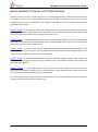
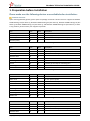
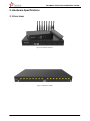
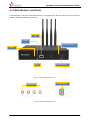
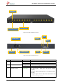
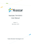
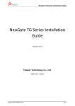
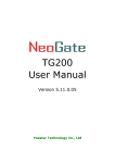
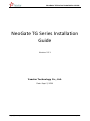
NeoGate TG Series Installation Guide NeoGate TG Series Installation Guide Version: V1.1 Yeastar Technology Co., Ltd. Date: Sept. 2, 2014 http://www.yeastar.com 1/14 NeoGate TG Series Installation Guide Contents 1. Preparation before Installation.................................................... 4 2. Hardware Specifications ........................................................... 6 2.1 Overview ............................................................................................................................................................. 6 2.2 LED Indicators and Ports ..................................................................................................................................... 7 2.3 Specifications and Operating Environment ......................................................................................................... 9 3. NeoGate TG Series Installation .................................................. 10 3.1 Placement Instructions ..................................................................................................................................... 10 3.2 Installation Instructions ..................................................................................................................................... 10 3.2.1 Connection of Ethernet Ports ..................................................................................................................... 10 3.2.2 Connection of GSM ports ........................................................................................................................... 10 3.2.3 Power Connection ...................................................................................................................................... 11 3.2.4 Indicators Status ........................................................................................................................................ 11 4. NeoGate TG Series Basic Configurations ........................................ 12 4.1 Factory Defaults ................................................................................................................................................ 12 4.2 Logging in the Web Configuration Panel ........................................................................................................... 12 4.3 Network Settings ............................................................................................................................................... 13 4.4 Make and Receive calls ..................................................................................................................................... 13 4.5 Reset to Factory Defaults .................................................................................................................................. 14 5. Conclusion ......................................................................... 14 http://www.yeastar.com 2/14 NeoGate TG Series Installation Guide About NeoGate TG Series VoIP GSM Gateway NeoGate TG Series is a series of VoIP GSM gateway connecting GSM Network to VoIP Network directly, which can support two-way communication: GSM to VoIP or VoIP to GSM. It is the best solution ever to connect IP-based telephone systems, softswitches, and IP-PBXs to GSM network; and also the best fallback solution when landline goes down. NeoGate TG100 is a fully featured 1 port VoIP GSM gateway that provides GSM network connectivity for softswitch and IP PBX. It significantly reduces the costs of calls with two-way communication: VoIP to GSM and GSM to VoIP. With friendly GUI, everything can be easily set up. NeoGate TG200 is a VoIP GSM gateway with 2 channels providing GSM network connectivity for softswitch and IP PBX. It supports two-way communication: VoIP to GSM and GSM to VoIP. Thus the calls costs could be significantly reduced by VoIP or GSM network. NeoGate TG400 is a compact 4 channels VoIP GSM gateway that connects GSM network with VoIP. It is the ideal product for small and medium sized companies with heavy demands of calls to mobile networks. The cost-saving solution makes connection cheaper and efficient. NeoGate TG800 is a powerful VoIP GSM gateway with 8 channels, bridging between GSM network and IP-based systems. Designed to slash the cost of telephone calls, it can find the cheapest route and use the most economical SIM card. NeoGate TG1600 is a VoIP GSM gateway with 16 channels providing GSM network connectivity for softswitches and IP-PBXs. It supports two-way communication: VoIP to GSM and GSM to VoIP. Thus the calls costs could be significantly reduced by VoIP or GSM network. This Guide explains how to install NeoGate TG Series Gateway, how to configure NeoGate TG Series Gateway via web interface, and how to insert SIM cards, etc. http://www.yeastar.com 3/14 NeoGate TG Series Installation Guide 1. Preparation before Installation Please make sure the following devices are available before installation: Contents of the box Upon receiving NeoGate gift box, please open the package and check if all the items are supplied as NeoGate TG100 Packing List (See Sheet 1), NeoGate TG200 Packing List (See Sheet 2), NeoGate TG400 Packing List (See Sheet 3), NeoGate TG800 Packing List (See Sheet 4), and NeoGate TG1600 Packing List (See Sheet 5). If there is any problem, please contact your equipment provider. Item Unit QTY Description NeoGate TG100 PC 1 NeoGate TG100 main box Power adaptor PC 1 Power Supply Warranty card PC 1 With Series Number printed for Repair & Return Antenna (short) PC 1 Sheet 1 NeoGate TG100 Packing List Item Unit QTY Description NeoGate TG200 PC 1 NeoGate TG200 main box Power cord PC 1 For the input of power Warranty card PC 1 With Series Number printed for Repair & Return Network cable PC 1 Antenna PC 2 Mounting ear PC 3 Screws PC 9 Grounding stud and nut Pair 1 Rubber feet PC 4 9 screws (φ3.0*6mm) for mounting ears Sheet 2 NeoGate TG200 Packing List Item Unit QTY Description NeoGate TG400 PC 1 NeoGate TG400 main box Power cord PC 1 For the input of power Warranty card PC 1 With Series Number printed for Repair & Return Network cable PC 1 Antenna PC 4 Mounting ear PC 3 Screws PC 9 Grounding stud and nut Pair 1 Rubber feet PC 4 9 screws (φ3.0*6mm) for mounting ears Sheet 3 NeoGate TG400 Packing List Item Unit QTY Description NeoGate TG800 PC 1 NeoGate TG800 main box Power cord PC 1 For the input of power Warranty card PC 1 With Series Number printed for Repair & Return Network cable PC 1 http://www.yeastar.com 4/14 NeoGate TG Series Installation Guide Antenna PC 8 Mounting ear PC 2 Screws PC 8 Grounding stud and nut Pair 1 Rubber feet PC 4 8 screws (φ3.0*6mm) for mounting ears Sheet 4 NeoGate TG800 Packing List Item Unit QTY Description NeoGate TG1600 PC 1 NeoGate TG1600 main box Power cord PC 1 For the input of power Warranty card PC 1 With Series Number printed for Repair & Return Network cable PC 1 Antenna PC 4 or 16 Mounting ear PC 2 Screws PC 8 Grounding stud and nut Pair 1 Rubber feet PC 4 4 antennas for TG1600 that supports antenna splitter 8 screws (φ3.0*6mm) for mounting ears Sheet 5 NeoGate TG1600 Packing List http://www.yeastar.com 5/14 NeoGate TG Series Installation Guide 2. Hardware Specifications 2.1 Overview Figure 2-1 NeoGate TG Series Figure 2-2 NeoGate TG1600 http://www.yeastar.com 6/14 NeoGate TG Series Installation Guide 2.2 LED Indicators and Ports The LED indicators and ports of NeoGate TG Series are straightforward. Take the front panel and rear panel of NeoGate TG400 and TG1600 as an example. LAN POWER GSM PORT STATUS RESET RUN SIM CARD SLOT Figure 2-3 NeoGate TG400 Front Panel ANTENNA POWER INLET Figure 2-4 NeoGate TG400 Rear Panel http://www.yeastar.com 7/14 NeoGate TG Series Installation Guide ANTENNA SIM CARD SLOT GSM PORT STATUS Figure 2-5 NeoGate TG1600 Front Panel LAN POWER POWER INLET RESET PROTECTIV E EARTH POWER SWITCH RUN CONSOLE Figure 2-6 NeoGate TG1600 Rear Panel LED Power Indication Power status RUN NeoGate status 1-16 GSM port status http://www.yeastar.com Status Description On The power is switched on. Off The power is switched off. Blinking NeoGate is running properly. Not Blinking/Off NeoGate goes wrong. Green light The green light is solid green: the port is working properly. The green light is blinking: there is an ongoing call on the port. The green light is off: no SIM card is detected or the port is not working properly. 8/14 NeoGate TG Series Installation Guide Ports Antenna ports Ethernet ports Description For the connection of GSM Antennas. NeoGate TG Series provides 1 10/100 adaptive RJ45 Ethernet ports, marked as LAN. -LAN port: LAN port is for the connection to Local Area Network (LAN). Press the reset button to restore the factory defaults. Please make sure that you want to reset, because once reset the previous configurations would be erased automatically. For the connection of a power adapter. Reset button Power inlet Console port (TG800 and TG1600) For debugging. 2.3 Specifications and Operating Environment TG100 Description Size (L×W×H) 110×70×24 (mm) Power Supply AC 100~240V/50–60Hz (DC 12V, 1A) Operating Temperature 0°C–40°C (32°F–104°F) Storage Temperature -20°C–65°C (-4°F–149°F) Humidity 10%~90% (Non-condensing) TG200/TG400 Description Power Supply 213×160×44 (mm) 100-240V 50/60Hz 0.5A MAX Operating Temperature 0°C–40°C (32°F–104°F) Storage Temperature -20°C–65°C (-4°F–149°F) Humidity 10%~90% (Non-condensing) Size (L×W×H) TG800 Description Size (L×W×H) 340×210×44 (mm) Power Supply 100-240V 50/60Hz 1.5A MAX Operating Temperature 0°C–40°C (32°F–104°F) Storage Temperature -20°C–65°C (-4°F–149°F) Humidity 10%~90% (Non-condensing) TG1600 Description Size (L×W×H) 440x280x44 (mm) Power Supply 100-240V 50/60Hz Operating Temperature 0°C–40°C (32°F–104°F) Storage Temperature -20°C–65°C (-4°F–149°F) Humidity 10%–90% (Non-condensing) http://www.yeastar.com 9/14 NeoGate TG Series Installation Guide 3. NeoGate TG Series Installation To avoid unexpected accident, personal injury or device damage, please read the following instructions before installing NeoGate TG Series Gateway. 3.1 Placement Instructions Ambient Temperature: to avoid overheating, please do not run NeoGate TG Series in the place where the ambient temperature is above 104°F (40°C). Ventilation: please make sure that the device has good ventilation around. Anti-jamming: there may be some sources of interference that might affect the normal running of NeoGate. It’s highly recommended that the device Should be placed away from high-power radio, radar transmitters and high frequency, and high-current devices. Is using independent power junction box and effective anti-grid interference measures have been taken. Mechanical load: Please make sure that the device is placed steadily to avoid any accident that might cause damage. If placed on the desktop, please ensure it is horizontally placed. 3.2 Installation Instructions After placing NeoGate in a suitable place, please connect the power adapter and all other cables to complete the installation. 3.2.1 Connection of Ethernet Ports NeoGate TG Series provides one 10/100M adaptive RJ45 Ethernet LAN port. LAN Port Connection Connect one end of a network cable to the LAN port of NeoGate, and the other end to any port of company’s LAN switch/router. If the LAN port is connected to PC directly (not via a switch), please use cross-over cable. 3.2.2 Connection of GSM ports NeoGate TG Series, available with four models, supports 1, 2, 4, 8, 16 GSM ports. To use the GSM ports, you need to insert the SIM card and connect the antenna. 1. 2. Connect the antenna. Connect the antenna to the relevant place. Insert SIM cards. Push the SIM card into the card slot on the front panel. http://www.yeastar.com 10/14 NeoGate TG Series Installation Guide 3.2.3 Power Connection Once users have made sure that device installation, cable connection and power type are correct, please switch on the power. Then NeoGate will start booting. In the meantime, users would see that the “POWER” and “RUN” indicator lights turn on. Please switch off the power before plugging or unplugging the cables. 3.2.4 Indicators Status When power is connected, users should be able to find that the “Power” indicator, “RUN” indicator, and GSM port status indicator beside the slot that has installed SIM cards turn on. http://www.yeastar.com 11/14 NeoGate TG Series Installation Guide 4. NeoGate TG Series Basic Configurations 4.1 Factory Defaults NeoGate TG Series provides web-based configuration interface for administrator and account user. The user can manage the device by logging in the Web interface. The factory default IP address: LAN: 192.168.5.150; Access path: http://[IP address] User Name: admin; Password: password Default SIP UDP port: 5060 4.2 Logging in the Web Configuration Panel Firstly, please check if the IP address that assigned to the network port (LAN) is in the same segment with the PC and which can be connected when commit “Ping + NeoGate IP address” command. Start the browser on PC. In the address bar, enter the IP address, click “Enter” button and then you can see NeoGate Web Configuration Panel login page (See Figure 4-1). Figure 4-1 NeoGate Web Configuration Panel Login Page Enter the Admin User Name and Password to log in. http://www.yeastar.com 12/14 NeoGate TG Series Installation Guide Figure 4-2 NeoGate Admin Configuration Interface Via the configuration interface, the admin can make all the system configurations, including network settings (LAN, Firewall, VPN, DDNS, VLAN, etc.); system parameters configuration (time zone, password, etc.); internal settings (Web access port, etc.); route lists; module lists; call logs (search, download); firmware update and reset, etc. Please note that after saving the changes, remember to click the “Apply Changes” button to make the changes take effect. 4.3 Network Settings After logging in the admin configuration interface, generally the first step is to configure the IP address. If the LAN ports are connected to the network, their IP addresses need to be configured. If not, just configuring the IP address of the LAN port which is connected to the local area network of the company is OK. LAN Settings Click “Network Preferences”->”LAN Settings” on the left menu bar of the web configuration interface. LAN port is used for the interoperability of IP terminals and NeoGate. If the LAN port is connected to the company’s LAN, please configure the correct IP address and corresponding subnet mask. Please note that after changing the IP address of LAN port, NeoGate should be rebooted to make the new changes taking effect. 4.4 Make and Receive calls NeoGate TG Series supports SIP Peer mode. Users should be able to make and receive calls after configuring http://www.yeastar.com 13/14 NeoGate TG Series Installation Guide VoIP trunking, and Mobile to IP or IP to Mobile routes. Please refer to Administrator’s Guide for details. 4.5 Reset to Factory Defaults If you forget the new IP address or the password of admin, or in other cases that you would like to restore the factory defaults, please reset the device following the below instructions: Please press the “RESET” button located in the back panel with a paper clip or a pencil tip. You can see the RUN indicator stops flicker and turns solid. When the RUN indicator turns off, the button could be released and system begins to reset. During the process, please do not power off until the RUN indicator become normal which means the reset process is completed. Note: After resetting, all the configurations made by the admin would be erased. 5. Conclusion This Installation Guide only explains the installation and basic settings of NeoGate TG Series. For more functionality and advanced settings of NeoGate TG Series, please refer to the relative documents as below: “NeoGate TG Series Datasheet” “NeoGate TG Series Administrator’s Guide” [The End] http://www.yeastar.com 14/14