1
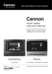
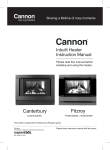
Gas Log Heaters Sharing a lifetime of cosy moments Power Flue Instruction Manual Please read this manual before installing and using this heater. Fitzroy Models: FITZIB-PDEXx x = Colour Canterbury Models: CANTIB-PDEEx This heater is approved for Natural and Propane gases Distributor This appliance is designed, manufactured and distributed by: Tel: 1300 727 421 Please leave instruction manual with the owner CONTENTS PAGE WARRANTY 3 SAFETY WARNINGS 5 OPERATION 6 OPTIONAL ACCESSORIES 7 FITZROY INBUILT POWER FLUE SPECIFICATIONS 8 CANTERBURY INBUILT POWER FLUE SPECIFICATIONS 9 REGULATORY LOCATOR 10 POWER FLUE INSTALLATION INSTRUCTIONS 11 – 14 FASCIA REMOVAL AND ELECTRICAL CONNECTION 15 LOG INSTALLATION & GAS CONNECTION 16 SETTING THE GAS PRESSURE 17 SERVICE INSTRUCTIONS 18 –19 WIRING DIAGRAM 20 TROUBLESHOOTING 21 – 22 NOTES 23 2 | Cannon Power Flue WARRANTY This Warranty against defects for your newly purchased Cannon product is proudly prepared by Sampford IXL Pty Ltd of 421 Smith Street, Fitzroy, VIC 3065, phone 1300 727 421. 1. Sampford IXL products come with guarantees that do not exclude the following consumer entitlements under the Australian Consumer law: a. replacement or refund for a major failure and compensation for any other reasonably foreseeable loss or damage; and b. to have the goods repaired or replaced if goods fail to be of acceptable quality and the failure does not amount to a major failure. 2. Sampford IXL warrants that your product and related supply will be free from defects in materials and workmanship during the warranty term. Your warranty term is 3 years, (10 years on the heat exchanger parts only), commencing from the date of purchase. Sampford IXL acknowledges this product requires professional installation and product removal is hazardous to consumers. Accordingly any necessary inspections and services will be carried out on site. You should not attempt de-installation. 3. Subject to Point 1, Sampford IXL will repair any defects in materials and workmanship during the warranty term and if the product is deemed irreparable provide a replacement of an equivalent current model where the balance of the warranty period from the original date of purchase will take effect. 4. To the fullest extent permitted by law and subject always to Point 1, Sampford IXL will not be liable for: a. any loss or damage arising from loss of use, loss of profits or revenue; or b. for any indirect or consequential loss or damage resulting from any breach of this warranty against defects. 5. Defective Sampford IXL products may be repaired using refurbished parts or if required, completely replaced by a refurbished product of the same type. Limitations to Your Cannon Warranty 6. Subject to Point 1, this Warranty: a. will only be provided to the original purchaser where the original purchase was made from a Sampford IXL Authorised Dealer or reseller and proof of such purchase can be presented at the time of service; b. only applies to Sampford IXL products purchased in Australia from a Sampford IXL Authorised Dealer or reseller and installed by a qualified person where a Certificate of Compliance in accordance with State/Territory laws is provided; c. will not apply where the defect in or failure of the product is attributable to misuse, abuse, accident or non-observation of the manufacturer’s instructions. This product must be used in accordance with the manufacturer’s instructions; d. will not cover faults due to normal wear and tear with reasonable use nor consumable components such as globes, filters, glass items, etc; e. will not cover any damages or problems caused to this product by natural forces eg. storm, fire, flood, and earthquake; or by intrusion or accumulation (or both) of foreign matters eg. dust, soil, and moisture. Sampford IXL recommends that you take out appropriate insurances to protect your product to this end; f. will not apply if this product is installed in a mobile dwelling eg. caravan or boat; g. will not apply if this product is removed from the location where it was first installed; h. is immediately void if the serial or model number label is removed or defaced; i. is immediately void if the product is serviced or repaired by a unauthorised/unqualified personnel; j. covers use of this product for domestic use only; k. will not be restarted or extended upon repair or replacement of the product or a part. How to Make a Claim Under Your Cannon Warranty 7. To make a claim under this Warranty you will need to: a. contact Sampford IXL service department on 1300 727 421 or aftersalesservice@sampfordixl. com.au to provide details and register your claim enabling a Sampford IXL assessment; b. submit proof of purchase with your claim eg. tax invoice or purchase receipt; c. where a property has been constructed by a builder/developer and it is fitted with Cannon products, please submit proof of purchase by way of the certificate of occupancy, with your claim. 8. Sampford IXL will contact you to make arrangements for service on site. 9. Subject to Point 1, you will be responsible for any costs relating to the provision of your product to a Sampford IXL Authorised Service Dealer. 10.Subject to Point 1, in the event you live more than 50 km from a Sampford IXL Authorised Service Dealer you may be subject to travel or transport costs to facilitate the repairing or replacement of your Cannon product. Cannon Power Flue | 3 11. Sampford IXL and its Authorised Service Dealers reserve the right to seek reimbursement of any costs incurred by them should your Cannon product be found to be in good working order. Privacy The privacy of your personal information has always been important to us. To learn more about how we collect, keep and use your personal information, please obtain a copy of our privacy statement by visiting our website at www.sampfordixl.com.au or by contacting us via email on [email protected] or by telephone on 1300 727 421. Enter the details of the date installed and the Compliance Certificate number in the appropriate area on the rear page of this manual. DO NOT operate this appliance before reading the instruction manual. DO NOT place articles on or against this appliance. DO NOT store chemicals or flammable materials, or spray aerosols near this appliance. DO NOT operate with panels, covers or guards removed from this appliance. DO NOT connect an LP gas cylinder located indoors. Don’t risk your appliance warranty. Only a licensed person will give you a Compliance Certificate, showing that the work complies with all the relevant standards. Only a licensed person will have insurance protecting their workmanship for 6 years. You MUST use a licensed person to install this appliance who MUST give you your Compliance Certificate to ensure the manufacturers appliance warranty will be honoured. 4 | Cannon Power Flue SAFETY WARNINGS Please read this manual before installing and using the heater. Safety Warnings 1. What to do if you smell gas a. Turn OFF the main gas supply b. Extinguish any open flame c. Open windows d. Do not touch electrical switches e. Do not use your telephone f. Call your gas supplier immediately from a neighbour’s phone 2. Improper installation, adjustment, alteration, service or maintenance can cause injury or property damage. Refer to the sections of this manual for correct procedures, or consult with place of purchase, a licensed plumber, a gas supplier or the Cannon distributor listed in this manual. 3. Install the heater only in locations that are referred to in the installation instructions. Do not build the heater into bookcases, walls or enclosures (combustible materials) without the use of an insulating blanket & stand off brackets fitted (supplied with heater). 4. Due to high temperatures the room heater should be located out of traffic and away from: • Furniture and draperies • Combustible materials • Gasoline and other flammable liquids Do not place clothing or other flammable material on or near the heater. 5. Keep curtains*, clothes, furniture and other flammable materials at least 900mm from front and sides of heater. * At the owner’s discretion curtain clearance can be less than 900mm as long as they are restrained from the front, top and sides of the heater. The manufacturer takes no responsibility if curtain clearance is less than 900mm and not restrained. 8. DO NOT PLACE ARTICLES ON OR AGAINST THIS APPLIANCE. DO NOT USE OR STORE FLAMMABLE MATERIALS NEAR THIS APPLIANCE. DO NOT INSTALL OR USE THIS APPLIANCE IN MARINE CRAFT OR MOBILE HOMES. DO NOT SPRAY AEROSOLS IN THE VICINITY OF THIS APPLIANCE WHILE IT IS IN OPERATION. DO NOT MODIFY THIS APPLIANCE. 9. If removed, the glass window must be put back onto the unit prior to operating the heater. 10. Installation and repairs must be performed by a licensed service person only, refer to back of manual for service number. 11. For installation into a non-combustible fireplace, i.e masonry or brick or into a mock fireplace, i.e. timber or plasterboard, the chimney and base should be of sound construction. 12. On first lighting your heater an odour and possibly some harmless smoke may be emitted due to its new condition. This is quite normal and will disappear after a few hours use. Important: When this heater is operating the mesh guard/glass front is hot. The mesh guard, or glass front is fitted to this appliance to reduce the risk of fire or injury from burns and no part of it should be permanently removed. For protection of young children or the infirm, a secondary guard is recommended (not supplied with heater). This appliance meets the following standards: Standards Australia AS/NZS 3100 AS/NZS 5601.1 AS 4553:2008 6. Children and adults should be alerted to the hazard of high surface temperatures and should take care to avoid burns or clothing ignition. This appliance is not intended for use by persons (including children) with reduced physical, sensory or mental capabilities or lack of experience and knowledge, unless they have been given supervision or instruction concerning use of the appliance by a person responsible for their safety. Children should be supervised to ensure that they do not play with the appliance. 7. Never attempt to burn paper or any other material in the heater. Cannon Power Flue | 5 OPERATION Operating Instructions Plug the power cord into the switch socket and turn on the power to the heater (FIG 1). Alternatively, switch on the isolation switch and circuit breaker at the main switchboard if the heater has fixed wiring. Refrain from using an extension cord. User controls FIG 2. • If there is an interruption to the power supply the heater will fail safely and switch off. When the power supply has been restored you MUST wait at least 5 minutes before turning the heater ON. Cleaning When there is power available to the heater and it is in the OFF or Standby mode, a red LED located inside the ON/OFF button will flash twice and will extinguish after approximately 3 seconds and then repeat this cycle continuously. To turn the heater ON press the ON/OFF button once. • turn the heater on again if there have been several attempts to ignite the heater without success. The LED will illuminate and an audible beep will sound but there will be approximately 30 seconds delay before the ignition system commences. On successful ignition the heater will operate on Low Fire and Low Fan for approximately 3 minutes then will switch to selected setting (if already chosen, otherwise will switch to NORMAL settings automatically). All cleaning should be carried out when the heater is cold. Normally the heater should only need wiping with a lint-free damp cloth. Any stubborn stains can be removed with a nonabrasive spray on cleaner. If an abrasive cleaner is used the paint finish will be damaged. For heaters fitted with the glass front: all cleaning should be carried out when the heater is cold. Clean the outer glass with a mild liquid or spray on glass cleaner. Do not use harsh abrasive cleaners or sharp metal scrapers to clean the heater glass front since they can scratch the surface, which may result in shattering of the glass. • The LED will extinguish approximately 30 seconds following the ignition startup. Internally the heater should only be cleaned by an authorised service person. If your heater requires attention contact your supplier or an authorised service person. • Select the desired heating level by pressing the LOW, NORMAL or BOOST button once as required. Flame Characteristics • LOW is LOW heat and LOW speed fan. BOOST is HIGH heat and HIGH speed fan. • To turn the heater OFF press the ON/OFF button once. An audible beep will sound twice to indicate the heater is off. The burner will extinguish but the fan will continue to operate for approximately 3 minutes. Remember that the fan will continue to operate for approximately 3 minutes after the OFF button has been pressed but you can turn the heater ON again without having to wait for the fan to stop operating. The heater flame should be stable, not lifting from the burner. The logs should glow after approximately 15 minutes operation on BOOST setting. • If the ignition system fails to ignite or keep the burner alight, the system will beep 4 times and go into safe shutdown mode. It will beep 4 times every 30 seconds to alert you to the fact. Press the ON/OFF button once to restart the heater during this time. You MUST wait at least 5 minutes before trying to ON / OFF The heater is designed to operate with luminous flames and may exhibit slight carbon deposit on the logs. If there is any excess carbon build-up on logs, or the burner flame is unstable, contact Sampford IXL in your state. Important The appliance MUST be serviced at least annually by an authorised service person. This maintenance cost is not covered under the warranty terms and conditions. More frequent cleaning may be required due to excessive lint build-up from carpeting, bedding materials, pet hair, etc. It is imperative that control compartments, burners and circulating air passage ways of the appliance be kept clean. Do not use this heater if the glass is cracked or with the safety screen removed. Do not use heater with broken or missing logs. LOW NORMAL BOOST FIG 1 6 | Cannon Power Flue FIG 2 High wind gusts can affect the heaters flueing and switch the heater off. If this happens, restart the heater as normal. If the problem persists contact Sampford IXL. OPTIONAL ACCESSORIES Versatility and flexibility are key components of our installation options. Install in a shallow recess or an existing fireplace, elegant spacers will eliminate any size discrepancies. To enhance your Cannon’s appearance add a decorative 3 or 4 sided surround. Every Cannon heater brings you the optional convenience of controlling your heater through a remote thermostat. For added convenience the heater can now be connected to a home automation system, such as C-bus. This allows the heater to be turned on or off remotely (normal heat setting only). Speak to your home automation specialist for further information. CONSOLE KIT - REFER TO THE INSTRUCTIONS PROVIDED WITH THE CONSOLE KIT FOR SPECIFIC INSTALLATION DETAILS. Product codes 50 mm spacer kit: Spacer kit Canterbury mesh kit Fitzroy mesh kit 3 sided surround kit Weatherproof kit Console kit 4 sided surround kit Remote thermostat FITZ Black BSPACERX-B FITZ Platinum BSPACERX-P CANT Black BSPACERE-B CANT Platinum BSPACERE-P Mesh kits: CANTIBMG-B FITZPWRMG-B 3 sided surround kit: FITZSURROUND3SX-B (Black) FITZSURROUND3SX-P (Platinum) FITZSURROUND3SX-S (S/Steel) CANTSURROUND3SX-B (Black) CANTSURROUND3SX-P (Platinum) Weatherproof kit: WPBPF13 Powerflue console kit: CONSPWRFITZ-B (Black) CONSPWRFITZ-P (Platinum) CONSPWRCANT-B (Black) CONSPWRCANT-P (Platinum) 4 sided surround (All models): SURROUND4SX-B (Black) SURROUND4SX-P (Platinum) SURROUND4SX-S (S/Steel) Remote Thermostat: RTKIT Extended Flue Kit: FLUEWFX Extended flue kit Cannon Power Flue | 7 FITZROY INBUILT POWER FLUE SPECIFICATIONS Cannon Fitzroy Inbuilt Power Flue Please Note: The data label is located in the fan chamber. Access by removing front fascia. Gas type Natural or Propane gas, as indicated on data label Gas consumption 26.0 MJ/hr input Energy output 6.42 kW / 23.11 MJ/hr Energy star rating 5.55 stars Heater type Gas space heater approved to AS 4553:2008 Operating pressure Natural gas 0.75 kPa (High) / 0.40 kPa (Low) Propane gas 2.65kPa (High) / 1.1 kPa (Low) Gas regulator Integral part of controller Min. inlet pressure 1.13 kPa (NG) 2.75 kPa (Propane) Fan 3 speed Ignition Electronic direct spark Power requirement 240V AC 10 Amp switch socket Power consumption 90 VA maximum Minimum cavity Height 605 mm* dimensions Width 700 mm* Depth 538 mm* Optional accessories • Safety mesh guard • Remote thermostat • Spacer kit • 3 sided surround • 4 sided surround • Console kit • Extended flue kit • Weatherproof box Overall dimensions Refer to FIG 3 * For installation into a masonry/brick fireplace 488 mm 376 mm 112 mm 600 mm 50 mm GAS SUPPLY 186 mm FIG 3 Front View and Side View of Fitzroy 8 | Cannon Power Flue CANTERBURY INBUILT POWER FLUE SPECIFICATIONS Cannon Canterbury Inbuilt Power Flue Please Note: The data label is located in the fan chamber. Access by removing lower fan chamber panel. Gas type Natural or Propane gas, as indicated on data label Gas consumption 26.0 MJ/hr input Energy output 6.42 kW / 23.11 MJ/hr Energy star rating 5.55 stars Heater type Gas space heater approved to AS 4553:2008 Operating pressure Natural gas 0.75 kPa (High) / 0.40 kPa (Low) Propane gas 2.65kPa (High) / 1.1 kPa (Low) Gas regulator Integral part of controller Min. inlet pressure 1.13 kPa (NG) 2.75 kPa (Propane) Fan 3 speed Ignition Electronic direct spark Power requirement 240V AC 10 Amp switch socket Power consumption 90 VA maximum Minimum cavity Height 605 mm* dimensions Width 700 mm* Depth 472mm* Optional accessories • Safety mesh guard • Remote thermostat • Spacer kit • 3 sided surround • 4 sided surround • Console kit • Extended flue kit • Weatherproof box Overall dimensions Refer to FIG 4 * For installation into a masonry/brick fireplace 422 mm 310 mm 112 mm 125 mm 600 mm 653 mm 850 mm GAS SUPPLY 120 mm FIG 4 Front View and Side View of Canterbury Cannon Power Flue | 9 REGULATORY LOCATION MINIMUM CLEARANCES REQUIRED FOR BALANCED FLUE TERMINALS, FAN ASSISTED FLUE TERMINALS, ROOM SEALED APPLIANCE TERMINALS OR THE TERMINALS OF OUTDOOR APPLIANCES. j F j j Openable window k h Door See note 3 d P T I c e e h n a T h g M d k g T = Flue terminal I = Mechanical air inlet Ref a b c d e f g h j k n See note 2 M = Gas meter P = Electricity meter or fuse box Item b T Shading indicates prohibited areas for flue terminals Minimum clearances (mm) Fan Natural assisted draft Below eaves, balconies and other projections: Appliances up to 50 MJ/hr input 300 200 Appliances over 50 MJ/hr input 500 300 From the ground, above a balcony or other surface 300 300 From a return wall or external corner 500 500 From a gas meter (M) (see 4.7.11 for vent location of regulator) 1000 1000 From electricity meter or fuse box (P) 500 500 From a drain pipe or soil pipe 150 75 Horizontally from any building structure or obstruction facing a terminal 500 500 From any other flue terminal, cowl, or combustion air intake 500 500 Horizontally from an openable window, door, non-mechanical air inlet or other opening into a building with the exception of sub-floor ventilation: Appliances up t 150 MJ/hr input 500 300 Appliances over 150 MJ/hr input up to 200 MJ/hr input 1500 1500 Appliances over 200 MJ/hr input 1500 1500 All fan assisted flue appliances, in the direction of discharge 1500 From a mechanical air inlet, including a spa blower 1500 1500 Vertically below an openable window, non-mechanical air inlet, or any other opening into a building with the exception of sub-floor ventilation: Space heaters up to 50 MJ/hr input 150 150 Other appliances up to 50 MJ/hr 500 500 Appliances over 50 MJ/hr input and up to 150 MJ/hr input 1000 1000 Appliances over 150 MJ/hr 1500 1500 - unless appliance is certified for closer installation Notes: 1 All distances are measured to the nearest part of the terminal. 2 Prohibited area below electricity meter or fuse box extends to ground level. 3 See clause 5.13.6.6 for restrictions on the flue terminal under covered areas. 4 See Appendix J. Figures J2(a) and J3(a), for clearances required from a flue terminal to an LP Gas Cylinder. A flue terminal is considered to be a source of ignition. 5 For appliances not addressed above acceptance should be obtained from the technical regulator. THE POWER FLUE HEATER IS FAN ASSISTED. SEE COLUMN HIGHLIGHTED Special Note: This chart MUST be read in-conjunction with the full Australian Standard Gas Installations AS/NZS 5601.1 FIG 5 10 | Cannon Power Flue POWER FLUE INSTALLATION INSTRUCTIONS This heater is supplied with stand off brackets and insulation blanket for installation into combustible materials. Do not remove any when installing into a combustible enclosure. Make sure blanket has not moved during transit. Insulation blanket should be resting firmly against front fascia prior to affixing to wall. Please dispose of packaging appropriately. Keep away from children. Clearances For minimum clearances refer FIG 6 and FIG 7. Note: Ensure that the room air fan opening under the heater is not obstructed. Ensure the minimum clearances to combustible materials are maintained during installation, including adequate space for the proper operation and servicing of the heater. For clearances to furniture and curtains refer to warning on page 5. Flue Options The heater is supplied with components to suit a horizontal flue coming through a wall at the back of the heater. The components include a flue cowl which is designed to be fitted to the outside wall with suitable fasteners, a condensate drain tube 2m in length, a clamp and flexible flue sealant. Flexible ducting is provided to attach the heater to the flue cowl. The use of this flexible ducting provides for some flexibility in the manner the exhaust flue and intake air are connected. The exhaust flue and air intake components MUST be fully attached to the heater prior to the heater being fitted into the cavity. It is important to ensure the exhaust gas flue pipe has the ability to drain condensation either back into the heater or out through the terminal when installed horizontally. The exhaust gas flue pipe must not trap and collect condensation. This will adversely affect the performance of the heater. When flueing through the roof, the Extended Flue Kit is required (code FLUEWFX). The maximum length of flue pipes that can be used with the Power flue heater is 6.0m. Cavity Requirements The cavity must be prepared to accept the heater first. Before cutting any flue opening in the external wall, the finished floor level must be known. This floor level must include any tiling, loose hearth or panels which will support the heater. All clearances shown in FIG 6 - FIG 7 must be adhered to. If heater is going to be installed into an elevated cavity, ensure both flexible pipes, along with condensation hose are fully extended so they remain as straight as possible when sliding heater into position. Avoid trapping or kinking flue pipes. Note: The appliance must be secured at the front to a vertical face. Where this is difficult due to building inaccuracies, limited non-combustible packing may be used to obtain a suitable vertical surface. Method of fixing to finished wall surface (plaster/masonry/brick): suitable fixtures which are able to be easily removed must be used. 1000mm MIN TO CEILING Overview 1. This appliance MUST be installed by an authorised service person only. 2. This appliance shall be installed in accordance with the manufacturer’s installation instructions, local gas fitting regulations, municipal building codes, electrical wiring regulations, and AS/NZS 5601.1 the Australian Standard for Gas Installations. 3. Open top of carton and remove accessories (logs, flue cowl and flue pipes). Lift carton up and remove. Remove the four transit screws fixing the heater to the pallet. Check that the heater is suitable for the gas available. Refer to the data label located within the fan chamber (Bottom most area with fascia removed). 300mm MIN A C B FIG 7 Brick Fireplace Opening Fitzroy Brick Fireplace Mock Fireplace Max Min Min Max Height (A) 605 mm 640 mm 630 mm 640 mm Width (B) 700 mm 760 mm 730 mm 760 mm Depth (C - Horizontal Flue*) 538 mm 538 mm NA NA Depth (C - Vertical Flue*) 588 mm NA 588 mm NA Canterbury Brick Fireplace Mock Fireplace Min Max Max Min 605 mm 640 mm 630 mm 640 mm 700 mm 760 mm 730 mm 760 mm 472 mm NA 472 mm NA 522 mm NA 522 mm NA FIG 6 Note: *In the event that space constraints inhibit the installation process where it is not possible to maintain a 50mm or 100mm cavity depth clearance for ease of installation these clearances can be reduced, however under AS5601 guidelines a minimum clearance of 25mm to combustibles must be maintained at all times. Cannon Power Flue | 11 POWER FLUE INSTALLATION INSTRUCTIONS Mark and cut hole in rear 80 mm Gas Supply Wall of the cavity for flue and condensation drain Floor MUST be smooth and flat X FIG 8 100 mm ** ** Ensure controls are visible FIG 9 Front View 700 mm Fitzroy shown. (Same dimensions for Canterbury) Preparing The Cavity 120 mm 160 mm DIA FLUE OPENING 20 mm DIA CONDENSE DRAIN HOLE The power flue heater is a high efficiency unit extracting heat which in other heaters would escape in the flue gasses. Condensate from the flue gasses will be produced from this heater. 605 mm 288 mm 410 mm 450 mm A condensate drain pipe fixed to the exhaust flue outlet MUST have a condensate hose connected to it to allow for any condensation to drain out of the house. This hose must be fitted prior to installation of the heater into the cavity. FIG 10 Front View GAS SUPPLY 266 mm 41 mm 695 mm NOTE: X = 50 mm for Non Combustible Surfaces X = 100 mm for Combustible Surfaces The floor of the cavity MUST be smooth, flat and level. If you desire a template, use a sheet of stiff cardboard or MDF (medium density fibre board) cut to represent the rear of the heater. Mark a vertical centre line and an appropriate circle 450mm from the bottom indicating the flue position cut out. Refer FIG 10. Using your template as a guide, mark the flue cutout on the rear wall of the cavity and cut through from either the inside or the outside to produce a neat round hole in the external wall. Air Inlet Flue Outlet Condensate Drain Two lengths of flexible aluminium hose is supplied with the heater. These hoses can be stretched to 1 m lengths. FIG 11 2m 379 mm m Slip the flexible aluminium hose over the flue exhaust outlet with a hose clamp. Tighten the hose clamp to ensure the hose is securely attached to the flue exhaust outlet. 51 Place a liberal amount of silicon sealant to the inside of the flexible flue pipe which is to be mounted onto the flue exhaust outlet. *1* 2m 51 m The flexible aluminium hose is attached to the air inlet in the same manner, however there is no need to apply the silicon sealant on the air inlet. 25 mm MI N *2* 25 mm N MI Secure condensate tube to drain pipe using supplied clamp. Note: *1* For any horizontal application the top hat section can be removed. *2* Condensation drain hose MUST have sufficient fall to provide adequate drainage. Ensure no water traps in drain hose. 12 | Cannon Power Flue FIG 12 Corner Wall Application Fitzroy shown. (Same dimensions for Canterbury) POWER FLUE INSTALLATION INSTRUCTIONS Bend gas pipe and electrical entry tags inwards to allow cable and gas pipe to enter easily. Fully extend the flexible flue and air intake and position these pipes through the hole drilled through the wall. Route condensate tube through smaller hole in wall. Align the gas supply pipe with its entry point and the flue with the cutout in the rear wall. Slowly slide the heater into position until the mounting face comes into contact with the vertical wall. FIG 13 Note: As heater is slid into position, ensure that condensate and flexible flue pipes are fed through their respective holes. It may be advisable when the heater is positioned halfway into cavity to check hoses from outside to ensure that they are not kinked. Refer FIG 13 & FIG 14. SUITABLE FIXING SCREW The flue terminal conical rain hat section may be removed for horizontal installations. Refer FIG 15 & FIG 18. FIXING SLOTS IN HEATER FRONT Fitment Of Flexible Pipes To Flue Terminal. The flexible tubing is now fully extended out of the hole in the wall. 1. FIG 14 Fitzroy shown (same as Canterbury) Cut the tubing so that 20mm is extending past the wall opening. PVC VENT 2. Fit the stainless steel tubing to the flexible pipe from the flue exhaust outlet, using silicon sealant to seal the join and a hose clamp. 3. Fit the PVC tubing and the air inlet to the other flexible tube, using a hose clamp. 4. Place terminal cover plate over both air intake and exhaust air pipes. 5. Fit the stainless tube into the centre pipe of the flue terminal. 6. Using the included cable tie fix, the air inlet hose to the flue pipe. FLUE TERMINALl STAINLESS STEEL PIPE CLAMP FIG 15 Exhaust Air Intake FIG 16 Bend tabs on terminal cover and secure terminal to cover using screws provided. Refer to Australian Standard Gas Installations AS/NZS 5601.1 for ‘location of powerflue terminal’. PVC PIPE PVC ADAPTOR 7. Fix terminal cover to outside wall using suitable fixtures which are able to be easily removed. Make sure the terminal cover is affixed correctly with the cover tapering in a downward direction. This will ensure when the flue terminal is engaged to the terminal cover it will be slightly angled to allow for condensation to escape. 8. Fitzroy shown (same as Canterbury) TERMINAL COVER PLATE PLACED TO HAVE TERMINAL ON AN INCLINE. EXTERNAL WALL TERMINAL COVER PLATE (268mm x 248mm) FLUE TERMINAL WALL FIXING: USE SUITABLE FASTENERS FOR WALL CONSTRUCTION FIG 17 Cannon Power Flue | 13 FASCIA REMOVAL / INSTALLATION Removing Fitzroy Fascia (refer FIG 18a) 1. Remove the wire mesh guard by gently lifting it upwards and then outwards. Similarly remove a fitted glass kit by also gently lifting it upwards and then outwards. lifting out from the bottom. Place glass in a safe position for refit later. Removing Canterbury Fascia (refer FIG 18b) 1. Remove 4 M5 screws fixing the glass surround. To remove glass surround pull it firmly towards you. 2. Remove the lower front cover by unscrewing two M5 screws through the air intake slots. Unit is fitted with electronic switches. Ensure that the cable cannot be trapped when the heater is installed. 3. Remove the surround by pulling the lower section 3. To fully remove the fascia, unclip the switch cable from towards you gently to partly disengage it from the body the PCB connector and unclip the cable from the clipping of the heater, then gently lift it vertically to completely points. The cable is routed through a plastic grommet disengage it. which will have to be removed from the base panel. 4. To fully remove the fascia, unclip the switch cable from Refer FIG 19. the PCB connector and unclip the cable from the clipping points. The cable is routed through a plastic grommet Inner Glass Removal which will have to be removed from the base plate. To remove the inner glass loosen off all the clamp screws Refer FIG 19. and completely remove the upper clamps and one vertical side. Try not to touch the front surface of the glass. Fixing of the Fitzroy or Canterbury Fascia To avoid finger marks use suitable cloth. Remove the glass You MUST NOT fix the front fascia to the wall. by sliding the glass sideways out of the clamp and then The front fascia shall only be fixed to the heater. 2. Remove 4 M5 screws fixing the fascia assembly to the heater body. Bring the bottom of the fascia towards you gently to partly disengage it from the body of the heater. After it has been disengaged gently lift it up vertically to completely disengage it from the body of the heater. To fully remove the fascia, unclip the switch cable from the cable connector on the PCB and unclip the cable from the clipping points on the rear of the fascia. FIG 18a Removing Fitzroy Fascia FIG 18b Removing Canterbury Fascia FIG 19 ELECTRICAL CONNECTION Electrical Connection This appliance is designed to operate on 240V AC power supply. Failure to operate unit at correct supply voltage may create unsafe conditions. The heater is supplied with a flexible power cord with a plug fitted. A 10 Amp switch socket MUST be located within 1.5m of the heater. For installations where the power point is located outside of the enclosure, locate the power cord in the fascia cut out on the left or right hand side as required. For a power supply connection located inside the enclosure, run the power cord through the cord access located on the rear panel by pushing the cord access plate from the bottom. The rubber grommet that is fitted over the cord must be located correctly in the cut out of the cord access plate. Refer FIG 20. externally for servicing or emergency shut down of the heater. All fixed wiring MUST be installed by a suitably qualified person and comply to the appropriate electrical wiring rules. It is critical that the appliance is earthed and that the active and neutral are not reversed. Issues arising from incorrect electrical wiring at premises will not be covered under warranty (including use of extension cords). We recommend that the heater is connected directly to a switch socket by its own power cord. Refrain from using extension leads. Grommet Restore the cord access plate to the original position and seal with an appropriate removable material. A suitable double pole isolation switch MUST be installed 14 | Cannon Power Flue FIG 20 LOG INSTALLATION 1. The burner is contained within the burner chamber. Refer FIG 21. 2. Carefully unpack the log set. Logs are numbered as follows: #1 - Left front log #2 - Left back log #3 - Right front log #4 - Right back log Position the four individually numbered logs in the following order on the burner bed as shown in FIG 22-25. The locating pins on burner bed must engage with corresponding holes in the individual logs. Burner In Base Of Burner Chamber FIG 21 a) Place log #1 into the 2 front left pins on the burner bed, ensuring that the charring faces the front. Refer FIG 22. b) Place log #2 onto the 2 left back pins. Refer FIG 23. c) Place log #3 on single right front pin, ensure fork locates over log #2. Refer FIG 24. FIG 22 FIG 23 FIG 24 FIG 25 d) Place log #4 on single right back pin, ensure left side of log rests on depression in #3 log. Refer FIG 25. 3 Refitt the inner glass, making sure not to over tighten the screws. 4. Reconnect switch loom to the fascia switch set. 5. Refit the front fascia. GAS CONNECTION 1. Push the gas inlet access plate into the heater cabinet and slide the heater into the fireplace ensuring that the gas inlet pipe is fed through the hole located at the rear right hand side of the heater at the bottom. Refer FIG 26. Solid Copper Pipe To Be Used Only 2. With heater in position, flanges should be hard against masonry. Secure case flanges to the masonry. Screw or bolt the flange through the slots provided. 3. Connect the gas supply pipe to the copper compression fitting provided (we recommend using a basin wrench). Push the gas inlet plate down to its original position and seal with an appropriate easily removable material. Do not seal with a silicone sealant as the heater must be easily removable. Sealing is important as it prevents any leakage of flue products into the room. Test all connections for gas leaks. FIG 26 Same for Canterbury and Fitzroy 41 mm Note: The appliance must be secured at the front to a a vertical face. Where this is difficult due to building inaccuracies, limited non-combustible packing may be used to obtain a suitable veritcal surface. Method of fixing to finished wall surface (plater/masonry/brick) suitable fixtures which are able to be easily removed must be used. Gas Inlet Gas Connection ½ Inch Compression 82 mm FIG 27 Same dimensions for Canterbury and Fitzroy 4. Heater MUST NOT be connected using a flexible hose. Cannon Power Flue | 15 SETTING THE GAS PRESSURE 1. Gas valve layout is as indicated in FIG 28. Pressures for ‘Burner High Flame’ and ‘Burner Low Flame’ are factory set, however if pressures need to be checked or adjusted follow the procedures described below. To check outlet pressure at burner ‘High Flame’ and ‘Low Flame’ positions remove the plastic cap from the regulator adjustment location as indicated in FIG 29. 2. The pressure point is closed with a captive screw. Turn screw 6 revolutions anticlockwise to open the pressure point as indicated on FIG 30 (a) and place manometer tube over the test point as per FIG 30 (b). Pressure test point with captive screw Burner adjustment (Burner ‘Low Flame’) Plastic Cap Pressure adjustment (Burner ‘High Flame’) FIG 28 3. Switch the control buttons to ‘High Flame’ position. Wait for heater to switch to ‘BOOST’ setting (time delay on start up). Retain screwdriver in position and using a spanner adjust the outer nut on the control to give a high pressure reading (refer to specification table on page 8 & 9). (Turn clockwise to increase pressure and anticlockwise to decrease pressure). Refer FIG 31. 4. Switch the control buttons to ‘Low Flame’ position. Retain spanner in position and using a screwdriver adjust the central screw control to give a low pressure reading (refer to specification table on page 8 & 9). (Turn clockwise to increase pressure and anticlockwise to decrease pressure). Refer FIG 32. FIG 29 5. Remove spanner and screwdriver. Switch from BOOST to LOW to ensure settings are correct. 6. Switch heater off and remove the manometer tube. Tighten pressure test point by turning the captive screw fully clockwise. 7. Replace plastic cap. Ensure the little lug is positioned towards lower right hand side to clear the controls. (a) (b) FIG 30 8. Refit the fascia, making sure not to damage the power cord or switch cable. Adjust 9. Operate the heater on BOOST, NORMAL and LOW settings. The flame should be stable, no lifting from the burner and the logs should glow after approximately 15 minutes of operation on BOOST setting. If the flame is unstable: Hold • Check that the burner is located correctly. • Check that the glass front is located correctly and is against the sealing rope. FIG 31 • Check that the gas pressure is correctly adjusted. Hold • Check that flue is operating correctly. If the heater still does not operate to specification refer to the troubleshooting chart on page 20, or contact Sampford IXL in your state. Adjust FIG 32 16 | Cannon Power Flue SERVICE INSTRUCTIONS (DO NOT MODIFY THIS APPLIANCE) General 1. Service work MUST be carried out by authorised personnel only. 2. Unplug from wall socket or turn off power at isolation switch if heater is hard wired. 3. Always shut off the gas supply and ensure that the heater is cool before commencing any service operations. 4. Always check for gas soundness after servicing. To Replace Power Cord Contact Sampford IXL service department. To Replace The Gas Valve 1. Remove the fascia. Refer to page 14 of the installation instructions. 2. Unplug the cable from the gas control and disconnect the earth connection. 3. Disconnect the gas inlet (½” compression nut) connection at entry gas control and the 16mm nut at the outlet of the gas control. 4. Remove the three screws from the cradle retaining the gas control. 5. Remove gas control valve from heater. 6. Replace gas control and check for gas tightness. Note: Check the gas pressure on Boost and Low settings. Refer “gas control”, page 16. To Replace The Ignition Module 1. Remove the fascia. Refer to page 14 of the installation manual. 2. Unplug wire connectors from ignition module. 3. Lift ignition module from base panel. 3. Lift electronic controller from base panel. Note: Hook and loop mounting tape is used to secure electronic controller. 4. Replace the electronic controller. 5. Check and re-set gas pressures. To Replace The Inner Glass Refer to page 14 of the installation instructions. Fit the new glass. Note: Ensure the inside surface of the glass is clean and free from finger marks. To Replace The Burner And Spark/Sense Electrodes 1. Remove the logs from the burner chamber. Refer to page 15. 2. Remove the burner chamber front panel, 7 screws. 3. Disconnect the 16mm nut at the inlet of the injector. 4. Disconnect the spark and sense electrodes from the ignition module. 5. Remove the 2 M5 wing nuts from under the burner. Lift the burner assembly upwards and carefully remove from the burner chamber. Refer to FIG 34. 6. Replace in reverse order, checking correct location of spark/sense electrodes. Refer FIG 35. Spark gap between electrode and spark plate is 6 - 8 mm. Flame sense electrode MUST be in constant flame. Check for gas tightness. For log placement, refer to page 15 of this manual. Note: Hook and loop mounting tape is used to secure ignition box. 4. Replace ignition module and ensure that all wires are reconnected correctly. 5. Check and re-set gas pressures. To Replace The Electronic Controller 1. Remove the fascia. Refer to page 14 of the installation manual. 2. Disconnect the plugs on electronic controller. COMBUSTION FAN PRESSURE SWITCH ELECTRONIC CONTROLLER FIG 33 ROOM AIR FAN PRESSURE SWITCH IGNITION MODULE ROOM AIR FAN COMBUSTION FAN FIG 34 Securing the burner bed SPARK PLATE FLAME SENSE ELECTRODE SPARK ELECTRODE GAS VALVE FIG 35 Cannon Power Flue | 17 SERVICE INSTRUCTIONS (DO NOT MODIFY THIS APPLIANCE) To Replace The Fan Pressure Switch 1. Remove the fascia. Refer to page 14 of the installation instructions. 2. Remove the electronic controller. Refer to page 17. 3. Remove the connecting wiring from the pressure switch. 4. Remove the silicone tubes from the pressure switch. 5. The pressure switch is secured onto the rear of the fan chamber housing by two M5 screws. Remove the screws. 6. Replace the pressure switch. For wiring, one wire to “C”(Common) and the other to connect to “NO” (Normally Open). Polarity is not important. 7. Re-attach silicone tubes making sure that the black tube attaches to the black side of the pressure switch. Make sure that the tubes are not pinched or kinked. 8. Test operation of fan pressure switch - turn heater on low heat. If heater fails to light even when fan is spinning, refer to the fault codes on page 20. 5. Remove the venturi and bracket from the fan which was removed from the heater. Insert and secure the venturi and bracket on replacement fan. Note: “TOP” should point to air outlet of fan. 6. Insert fan into chamber ensuring that the venturi is not disturbed. Locate fan onto male thread. Secure with M5 wing nuts, ensuring rubber buffer locates over thread. 7. Replace silicone tubes onto fan pressure switch ensuring that the black tube is connected to the black side of the pressure switch. Check to make sure that the tubes are not kinked or pinche. Refer to FIG 37. 8. Reconnect fan plug into plug carrier. Test operation of room circulation fan and fan pressure switch. If heater fails to light even when fan is spinning, refer to fault codes on page 21. Switch Control Setting (FIG 36) For NG operation, DIL switch should be positioned in point ‘1'. For LPG operation, DIL switch should be positioned in pointer ‘O’. For audio beep function, DIL switch should be positioned in pointer ‘2'. To Replace The Room Circulation Fan 1. Remove the fascia. Refer to page 14 of the installation instructions. 2. Remove the electronic controller and ignition module. Refer to page 17. 3. Disconnect the fan plug from the plug carrier. Remove the two M5 wing nuts which locate the fan to the fan chamber underside. Lower fan from male thread. 4. Disconnect the silicone tubes from the fan pressure switch. Remove fan from fan chamber. GAS NG 1 O LPG ON 2 N OFF Clear Silicon Tube BEEP Black Silicon Tube FIG 36 Switch Control Diagram highlighting NG/LP settings & audible beep. 18 | Cannon Power Flue FIG 37 Room Fan SERVICE INSTRUCTIONS (DO NOT MODIFY THIS APPLIANCE) To Replace The Combustion Fan (FIG 38) 1. Disconnect the power supply to unit. 2. Remove the fascia. Refer to page 14 of the installation manual. 3. Remove the electronic controller and ignition module. Refer to page 17 of the installation manual. 4. Remove the room circulation fan. Refer to page 18 of the installation manual. 5. Disconnect the flexible pipe on the combustion fan. 6. Remove the four M5 screws as shown in FIG 38a. At all times the fan assembly should be supported from the rear. 7. Disconnect the silicone tubes from the combustion fan pressure switch. When refitting the pressure switch tubes, ensure they’re connected to the appropriate teat on the combustion fan. The clear tube fits onto the teat closest to the outlet of the combustion fan and the black tube fits onto the other available teat. 8. Rotate the combustion fan until the front of the fan is parallel to the top panel, shown in FIG 38b. Then remove the combustion fan making sure that it does not hit the male thread used to secure room circulation fan. 9. Disconnect the electrical wiring off the motor. 10.Repeat the steps above in reverse order to secure the combustion fan. Note: When reinstalling replacement fan, ensure it is adequately supported from the rear until at least two of the securing screws are in position. Do not bend or twist the fan assembly support plate. (a) REMOVE 4 SCREWS (b) MALE THREAD FOR ROOM CIRCULATION FAN SUPPORT PLATE FIG 38 Removing Combustion Fan WIRING DIAGRAM SWITCH ON/OFF COILS LOW BRN / LOW FAN MED BRN / MED FAN HIGH BRN / HIGH FAN SPARK ELECTRODE BLACK 3 WAY FLAME SENSOR SHEATHED HIGH TEMP DATA CABLE MODULATING VALVE F3590 WHITE EARTH BLUE RED RED COMBUSTION FAN - F3979 6 WAY ORANGE 2 WAY BLUE PURPLE RED 4 WAY RED 5 WAY 2 WAY BLUE NO NO PRESSURE SWITCH F4008 COMBUSTION FAN IGNITION MODULE F3435 POWERFLUE WIRING DIAGRAM 1 WAY PRESSURE SWITCH F3327 ROOM AIR FAN TH2 H M L CONTROL MODULE F3828 A EARTH C 4 WAY C BROWN 1.5 AMP[18] ROOM FAN - F3594 NC NC GREY MOD1 MOD2 BLUE RED 240 V MAINS PLUG N N C RED F3834 C FIG 39 Cannon Power Flue | 19 TROUBLESHOOTING To check the operation of the heater’s electrical system you will require a digital multimeter with the functions to measure AC/DC voltage, continuity, resistance and micro-amps. It is critical that the appliance is earthed and that the active and neutral are not reversed. Cannon Inbuilt Power Flue There is a green and red LED on the ignition controller. These LEDs act as diagnostic aids when the heater safety systems produce a safe shutdown condition. Green LED: this is on when the flame is sensed at the flame sensor electrode. Red LED: this flashes according to the fault code. No LEDs means there is no power to the ignition module. Check that the heater switch is set to ON by pressing the ON/OFF button. Check the supply voltage. Check the 1.5 Amp fuse, replace if necessary. It is critical that the appliance is earthed and that the active and neutral are not reversed. Do not use an extension cord. This appliance is designed to operate at 240V AC. Substantial voltage dips, or running the unit at voltages substantially lower than 240V AC may cause nuisance shutdowns. If there is still a problem check the power supply plug from the electronic controller with a multimeter (240V AC). If there is no power from this plug when the heater should be on, replace the electronic controller. Remember to re-test the gas pressures any time that the electronic controller is changed. It is recommended that any callout to a customer’s home should prompt the checking and resetting of the gas pressures. Fault Codes Long Short Morse Code Meaning 1 5 —••••• Normal start-up (30 second combustion purge) 1 0 — Normal operation 2 2 1 1 2 2 Action — —• Heater has attempted to light, however it did not sense flame within the allowed time. Check the gas supply to the unit is not switched off. Check the gas pressures. Check the flame and spark electrode connections and that they are positioned correctly. Ensure that the spark is being produced at the spark electrode tip, and is strong (clearly visible and around 6-8mm in length). Adjust if necessary. The burner tray is earthed through contact with the chassis. Check using a multimeter between the earth pin (or earth tab) and the burner tray. If the unit continues to spark after flame is present, ensure that the supply voltage polarity is not reversed. — —•• Flame was established, however the flame electrode has sensed that the flame has become unstable and has shutdown the gas. Check that the flame sense electrode and the spark plate are correctly positioned. Check the flame sense connections. Check that the flue is correctly constructed. Abnormally strong downdrafts can cause flame instability therefore it is recommended that an appropriate flue cowl is used for windy areas. Improper gas pressures can also cause issues. Check the gas pressures. —•• Check the fan for dust build up and lint. Check that the room air fan is spinning. Check that the pressure tubes are connected correctly and not pinched or kinked. The black tube should run from the black side of the pressure switch to the Room fan (circulation bottom tapping on the fan venturi. The clear tube should go fan) pressure signal from the light side of the pressure switch and to the top tapping not detected. on the venturi. Make sure that the pressure switch wires are connected correctly. One wire should be to C (Common) and the other should be to NO (Normally Open). If it still doesn’t work after checking the above, change the pressure switch. 20 | Cannon Power Flue TROUBLESHOOTING Fault Codes Continued Long Short Morse Code 3 1 — — —• 1 3 —••• 3 2 — — —•• 2 8 — —•••••••• Meaning Action Room fan (circulation fan) pressure signal has been interrupted. Check the fan for dust build up and lint. Check that the room air fan is spinning. Check that the pressure tubes are connected correctly and not pinched or kinked. The black tube should run from the black side of the pressure switch to the bottom tapping on the fan venturi. The clear tube should go from the light side of the pressure switch and to the top tapping on the venturi. Make sure that the pressure switch wires are connected correctly. One wire should be to C (Common) and the other should be to NO (Normally Open). If it still doesn’t work after checking the above, change the pressure switch. Check that the fan is spinning by starting the heater and either listening for the fan, or check to see if air is blowing out of the flue pipe. Check that the pressure tubes are connected correctly and not pinched or kinked. The black tube should run from the Combustion fan black side of the pressure switch to the bottom tapping on the pressure signal fan venturi. The clear tube should go from the light side of the not detected. pressure switch and to the top tapping on the venturi. Make sure that the pressure switch wires are connected correctly. One wire should be to C (Common) and the other should be to NO (Normally Open). If it still doesn’t work after checking the above, change the pressure switch. Check that the fan is spinning by starting the heater and either listening for the fan, or check to see if air is blowing out of the flue pipe. Check that the pressure tubes are connected correctly and not pinched or kinked. The black tube should run from the black side of the pressure switch to the bottom tapping on the fan venturi. The clear tube should go from the light side of the Combustion pressure switch and to the top tapping on the venturi. fan pressure Ensure that the condensate drain hoses are free flowing and not has been kinked or blocked. If the hoses are blocked, check that the interrupted. combustion fan is not filled with condensate. Ensure that the combustion fan drain is free flowing and that the combustion fan is dry prior to restarting the heater. Hoses to the pressure switch may also need to be checked that condensate has not entered these tubes. Make sure that the pressure switch wires are connected correctly. One wire should be to C (Common) and the other should be to NO (Normally Open). If it still doesn’t work after checking the above, change the pressure switch. Check the fan for dust build up and lint. Check that the room air fan is spinning. Check that the pressure tubes are connected Room fan correctly and not pinched or kinked. The black tube should run (circulation fan) from the black side of the pressure switch to the bottom tapping pressure switch on the fan venturi. The clear tube should go from the light side of has not switched the pressure switch and to the top tapping on the venturi. within the Make sure that the pressure switch wires are connected correctly. expected time. One wire should be to C (Common) and the other should be to NO (Normally Open). If it still doesn’t work after checking the above, change the pressure switch. Cannon Power Flue | 21 TROUBLESHOOTING Other Possible Faults No gas to burner. • The gas valve should open at the same time as the igniter sparks. If there is no gas to the burner when this occurs check the solenoid coils for continuity. • Check that the gas pressure is present at the test point when the spark is being generated. • Check that there is gas to the inlet of the gas control. Fuse blowing. • If the fuse continues to blow check the solenoid coils for a signs of them being shorted. • Check the fan and wiring for short circuit. NOTES 22 | Cannon Power Flue NOTES Cannon Power Flue | 23 COPY RATING LABEL HERE Don’t Risk Your Appliance Warranty Only a licensed person will give you a compliance certificate, showing that the work complies with all the relevant standards. And only a licensed person will have insurance protecting their workmanship for 6 years. So make sure you use a licensed person to install this appliance and ask for your compliance certificate to ensure the manufacturers appliance warranty will be honoured. Date Installed: Compliance Certificate No: Installed By: GMK 10030 AS4553:2008 Part Number: F4011_D 24 | Cannon Power Flue For service to this appliance or spare parts contact the CANNON distributor: Sampford IXL – Spare Parts Phone: 1300 727 421 Fax: 1300 727 425 Email: [email protected]