1
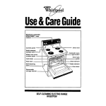
MT-60
Shown
OWNER'S MANUAL
MODULAR KETTLES
MODELS:
MT-5
MT5-5E
MT5-T56
MT-25
MT-40
MT-60
M-10
M-25
M-40
M-60
M25X
M40X
COVERING:
- INSTALLATION
- OPERATION
- MAINTENANCE
- SERVICE & PARTS
An Employee Owned Company
Form No. S-2110 08/03
Printed in U.S.A.
35 Garvey Street l Everett l MA l 02149
Tel: (617) 387-4100 Fax: (617) 387-4456 l (Outside MA) 1 (800) 227-2659
Website: www.mfii.com l E-Mail: [email protected]
l
TABLE OF CONTENTS
Paragraph
Page
SECTION 1 INTRODUCTION
1.1
1.1.1
1.1.2
1.1.3
1.1.4
1.2
Paragraph
Page
SECTION 3 maintenance
Description ............................................................. 1-1
5 Gallon Tilting Kettle ............................................. 1-1
10-, 25-, 40- & 60- Gallon Stationary Kettles ......... 1-1
25-, 40- & 60- Gallon Tilting Kettles ...................... 1-1
25- & 60- Gallon Chill Kettles ................................1-2
Service .................................................................. 1-2
3.1 General .................................................................. 3-1
3.2 Preventive Maintenance ........................................ 3-1
3.2.1 Cleaning .................................................................3-1
3.2.2 Tilting Mechanism .................................................. 3-1
3.3 Repair & Replacement ...........................................3-1
3.3.1 Lid Counterbalance Adjustment ............................. 3-1
3.3.2 Cabinet Exterior Removal ...................................... 3-2
SECTION 2 operation
2.1 Operating Controls & Indicators .............................2-1 3.3.3 5 Gallon Trunnion Mounted Kettle Disassembly .... 3-2
2.2 Operating Procedure - 5 Gallon Tilting Kettle ........ 2-1 3.3.4 Draw-Off Valve Repair ........................................... 3-2
3.3.5 Tilting Mechanism Repair .......................................3-2
2.3 Operating Procedure - 10-, 25-, 40- & 60- Gallon
Kettles .................................................................... 2-1 SECTION 4 illustrated parts list
2.4 Cleaning Procedure ............................................... 2-3 4.1 General .................................................................. 4-1
2.4.1 Cleaning 5 Gallon Tilting Kettles ............................ 2-3 4.2 Ordering Information .............................................. 4-1
2.4.2 Cleaning 10-, 25- & 40- Gallon Kettles .................. 2-3 4.3 Index of ILLUSTRATED PARTS LIST ....................4-1
A-1
2.5 Pan Support Mounting ........................................... 2-3
APPENDIX
list of illustrations
Figure
Page
SECTION 2 operation
2-1
Mounting Pan Support ........................................... 2-4
SECTION 3 maintenance
3-1
3-2
Lid Counterbalance Adjustment .............................3-1
Ball Nut Assembly ..................................................3-3
SECTION 4 illustrated parts list
4-1
4-2
4-3
4-4
4-5
4-6
4-7
5 Gallon Tilting Kettle .............................................4-2
Trunnion Pedestal ..................................................4-3
Faucet, 5 Gallon Tilting Kettle ................................4-4
10-, 25- & 40- Gallon Stationary Kettle .................. 4-5
60- Gallon Stationary Kettle ...................................4-6
25- & 40- Gallon Tilting Kettle ................................ 4-7
Tilting Mechanism 25- & 40- Gallon Kettle .............4-8
Figure
4-8
4-9
4-10
4-11
4-12
4-13
4-14
4-15
4-16
4-17
4-18
4-19
4-20
4-21
4-22
Page
60- Gallon Tilting Kettle ..........................................4-9
Tilting Mechanism 60- Gallon Kettle ...................... 4-10
25- & 40- Gallon Chill Kettle .................................. 4-11
Hinge & Lid Assembly ............................................ 4-12
Steam Supply Valve ...............................................4-13
Swing Dran ............................................................ 4-13
Draw-Off Valve .......................................................4-14
Steam-Trap ............................................................4-14
Faucet & Spout Assembly ..................................... 4-15
18" Cabinet ............................................................ 4-16
24" Cabinet ............................................................ 4-17
36" Cabinet ............................................................ 4-18
48" Cabinet ............................................................ 4-19
12" Spacer with Sink & Faucet .............................. 4-20
Accessories for Steam Jacketed Kettles ............... 4-21
list of TABLES
Table
Page
SECTION 2 operation
2-1
2-2
Operating Controls, 5 Gallon Kettle ....................... 2-2
Operating Controls, 10-, 25-, 40- &60- Gallon
Kettle ......................................................................2-2
Form No. S-2110 08/03
Printed in U.S.A.
i
SECTION 1 INTRODUCTION
This service and parts manual contains general information, operation, and maintenance information for Market Forge
modular kettles. A parts list is included in which each replaceable part is identified and shown in an accompanying
drawing. Accessories for use with the kettles are also described.
1.1 DESCRIPTION
1.1.2 10-,25-,40-, & 60-Gallon
Stationary Kettles
Market Forge Kettles include both stationary and tilting
steam jacketed kettles of five capacities, each mounted
in a modular stainless steel cabinet.
These units include large capacity kettles mounted in
fixed position in modular cabinet bases. A counterbalanced, hinged lid covers the kettle openings.
Double wall construction around the lower half of the
kettle forms a surrounding chamber into which steam is
introduced as a source of heat for cooking.
Each is plumbed for direct connection to a remote steam
source. An optional cold water circuit to the steam jacket
is available for use with all models for quick cooling of
foods after cooking. See paragraph 1.1.4.
Steam input plumbing is equipped with a manual control
valve. Condensate is removed through a steam trap
connecting with the kettle drain plumbing assembly. A
swivel spout, hot-cold combination faucet provides a
source of water for addition to the kettle for cooking and
cleaning.
Applicable model designation include:
M-10 A 10-gallon 37 litre capacity stationary kettle
mounted in a 24" 609 mm wide cabinet base.
M-25 A 25-gallon 95 litre capacity
stationary kettle mounted in a 36" 914 mm wide
cabinet base.
M-40 A 4O-gallon 152 litre capacity
stationary kettle mounted in a 36" 914 mm wide
cabinet base.
M-60 A 60-gallon 228 litre capacity
stationary kettle mounted in a 36" 914 mm wide
cabinet base.
An optional 12" spacer unit with faucet and sink may be
used instead of the standard built-in faucet.
1.1.1 5 Gallon Tilting Kettle
The 5-gallon 191itre capacity kettle is mounted in a
trunnion assembly to the modular cabinet top. The
trunnion pivots include steam input and return
connections for the kettle.
1.1.3 25-, 40-, & 60-Gallon Tilting Kettles
A sink equipped with re- versible splash shield is built into
the cabinet top under the kettle pouring spout. Kettle
tilting is accomplished manually by moving a handle fixed
to the rim so as to rotate the kettle in a trunnion mount.
Large capacity kettles are fitted with heavy duty tilting
mechanisms operated bya removable hand crank. Each
model is equipped with a pan support which maintains
continuous alignment of serving pans under the pouring
spout at all levels of kettle elevation.
Applicable model designation include:
MT-5
A single kettle mounted on an 18" 457mm
wide cabinet base equipped for direct
connection to a remote steam source.
MT5-T5
Counterbalanced hinged lids cover the kettles in the
lowered position. All are plumbed for direct connection to
a remote steam source. An optional cold water circuit to
the steam jacket is available for use with all models for
quick cooling of foods after cooking. See paragraph
1.1.4.
Two kettles mounted side-by-side on a 36"
914mm wide cabinet base equipped for direct
connection to a remote steam source.
Form No. S-2110 08/03
Printed in U.S.A.
1-1
SECTION 1 INTRODUCTION
Applicable model designations include:
MT-25
A 25-gallon 94 litre capacity tilting kettle
mounted in a 36" 914mm wide cabinet base.
MT-40
A 40-gallon 152 litre capacity tilting kettle
mounted in a 36" 914mm wide cabinet base.
MT-60 A 60-gallon 228 litre capacity tilting kettle
mounted in a 48" 1219mm wide cabinet base.
1.2 SERVICE
1.1.4 25- & 40-Gallon Chill Kettles
A current Directory of Authorized Service Agencies
may be obtained by contacting:
Modular kettles are exceptionally reliable and durable
cooking equipment requiring a minimum of service other
than routine cleaning and preventive methods explained
in Section 3. Should repairs be required, a network of
authorized service agencies is available to a,ssist with
prompt service.
The chill kettle is a modified application of the stationary
models equipped with a built-in sink completely
surrounding the kettle. The kettle functions to instantly
suspend cooking by allowing kettle interior to be flooded
with cold water. Hot cooking water rises over the rim and
into the sink.
Customer Service Department, Market Forge
35 Garvey Street, Everett, Massachusetts 02149
Telephone: (617) 387-41 00
Customer Service Department, Market Forge
A further modification is the addition of a jacket cooling
system consisting of a cold water plumbing assembly
connected to the kettle jacket. The system is used in
conjunction with kettle flooding to rapidly cool the kettle
by allowing cold water to fill the steam jacket.
Canada, Ltd.
1375 Aimco Blvd., Unit 5
Mississauga, Ontario, Canada
Telephone: (416) 621-9252
The model and serial numbers must be referenced when
corresponding with Market Forge.
Applicable model designations include:
M25X A 25-gallon 95 litre capacity stationary kettle
mounted in a 36" 914mm wide cabinet with
overflow sink and jacket cooling system.
M40X A 40-gallon 152 litre capacity stationary kettle
mounted in a 36" 914mm wide cabinet with
overflow sink and jacket cooling system.
The data plate containing model and serial numbers
pertaining to the equipment is locatedinside the cabinet
door on the right vertical frame member.
Form No. S-2110 08/03
Printed in U.S.A.
1-2
SECTION 2 Operation
2.1 OPERATING CONTROLS & INDICATORS
2.3 OPERATING PROCEDURE- 10- 25- 40- &
60
GALLON KETTLES
All of the controls required to operate the kettles are
listed in Tables 2-1 and 2-2, together with an explanation
of location and a short functional description.
All kettles must be supplied with steam from a generator
which is remotely located. Consult steam generator
information or instruction plate and complete all start-up
instructions. Proceed with kettle operating procedure as
follows:
2.2 OPERATING PROCEDURE 5 GALLON
TILTING KETTLE
All 5 gallon kettles must be supplied with steam from a
generator which may be remotely located or built into the
same cabinet base on which the kettle is mounted.
Consult steam generator information or instruction plate
and complete all start-up instructions. Proceed with kettle
operating procedure as follows:
1. Check pressure gauge of steam supply source to
insure steam input is at 15 PSI 1.0 kg/cm2. For direct
connected steam, turn on external steam supply valve.
2. Check that Draw-Off Valve is tightly closed.
1. Check pressure gauge of steam supply source to
insure steam input is at 15 PSI 1.0 kg/cm2. For direct
connected steam, turn on external steam supply valve.
3. Lift kettle lid and place either a Solid or Perforated
Drain Disc over the drain inside kettle. Use solid disc
to retain liquids; perforated to strain liquids from
food.
2. Load kettle with foods to be cooked.
3. Add water for cooking by turning Swivel Spout over
kettle and using Combination Faucet.
4. Load kettle with foods to be cooked.
5. Add water for cooking by swinging spout over kettle
and using Combination Faucet.
4. Turn Steam Control Valve to full counter- clockwise
position to heat kettle content to an initial rapid boil.
6. Turn Steam Control Valve to full counter-clockwise
position to heat kettle content to an initial rapid boil.
5. Adjust subsequent cooking temperature by turning
Steam Control Valve. Turn clock-wise to reduce heat
and counter-clockwise to increase.
7. Adjust subsequent cooking temperature by turning
Steam Control Valve. Turn clockwise to reduce heat
and counter-clockwise to increase.
6. Close Steam Control Valve and remove food from
kettle as soon as cooking is complete to prevent overcooking. With Splash Shield in the rear, place food pan
on sink grate and tip kettle forward using the Kettle
Handle.
NOTE: Swivel Spout must be rotated clear of kettle
before tilting.
8. Close Steam Control Valve (full clockwise position)
when cooking is complete.
CAUTION: Food must either be removed from the
kettle immediately or cooled by a kettle jacket cooling
system to prevent over cooking.
7. Complete cleaning procedure (see paragraph 2.4.1).
9. For Chill Kettles use an external water source to flood
kettle interior with cold water until all hot cooking water
flow over kettle rim into sink.
Form No. S-2110 08/03
Printed in U.S.A.
2-1
SECTION 2 Operation
Table 2-1
Operating Controls - 5 Gallon Kettle
NAME
loaction
Kettle Handle
Kettle Rim
Steam Control Valve
Top, Left Side
Combination Faucet
Top, Right Side
Swivel Spout
Top, Beside Kettle
Sink wuth Splash Shield
Top, Front
Function
Grasped to Tilt Kettle for Pouring.
Controls Steam Folw to Kettle Jacket.
Controls Hot & Cold Water to Swivel Spout.
Direct Water into Kettle. Turns away for Kettle Tilting.
Accepts Kettle Drainage. Sheld Forward Protects
Operator from Splashing - Reverses for Stowage.
Table 2-2
Operating Controls - 5 Gallon Kettle
NAME
loaction
Function
Lid Handle
On Lid
Perforated Drain Disc
Inside Kettle on Drain
Covers drain to strain liquids when draw-off is opened.
Solid Drain Disc (Optional)
Inside Kettle on Drain
Covers drain to block it off.
Crank (Tilitng Kettles)
Front, Right Side
Steam Control Valve
Top, Right Side
Draw-Off Valve
Inside Cabinet, Left
Controls drainage of Kettle.
Swing Drain with Strainer
Inside Cabinet, Left
Accepts drainage from draw-off valve. Swings to side
to allow serving containers to be placed under drawoff valve.
Combination Faucet with
Swivel Spout
Top, Right Side
Controld hot & cold water to Kettle interior. Turns away
for kettle tilting & access.
Cold Water Valve (Chill
Kettles & others with
Optional Jacket Cooling
System)
Right, Front
Controls flow of water to steam jacket for rapid cooling
after cooking.
Basin Waste Drain
(Chill Kettles Only)
Left, Top
Pan Support
(Tilting Kettles Only)
Front, Top
Grasped to open & close Kettle Lid.
Raises & Lowers Tilting Kettles for pouring. Stowa on
Back of cabinet door when not in use.
Controls Steam flow to Kettle Jacket.
Accepts kettle overflow in chill kettle sink.
Holds serving pan in alignment with kettles for pouring.
(See Subsection 2.5)
Form No. S-2110 08/03
Printed in U.S.A.
2-2
SECTION 2 Operation
water jacket cooling system open the Jacket Cold
Water Valve (full counter-clockwise position) and
leave open until food temperature is sufficiently
lowered.
2.4.2 Cleaning 10-, 25-, 40- & 60-Gallon
Kettles
1. Wash the kettle with a long handled nylon bristle kettle
brush (Part No. 10-5308).
11. Remove food from stationary kettles. For liquids
rotate the Swing Drain to the side and fill food
containers from the Draw-Off Valve. For solids which
will not pass through the valve, use a ladle. An
optional stationary pan holder (Part No. 90-3427) can
be used to support pan during filling.
2. Empty wash water by opening Draw-Off Valve over
Swing Drain.
3. Remove Drain Disc (solid or perforated) from inside
kettle and clean.
4. Rinse kettle by flushing with hot water from the Swivel
Spout.
12. Remove food from tilting kettles. With Pan Support
mounted (see subsection 2.5), food pan in support,
and Crank installed in front of cabinet, turn crank
clockwise to elevate kettle for pouring. (Tilting
mechanism is infinitely adjustable and non-coasting in
kettle elevation and lowering). Liquid foods may also
be removed by use of the Draw-Off Valve as
explained in step 11 for stationary kettles.
5. Loosen hex nut on Draw-Off Valve and carefully
remove all parts. Clean and reassemble.
(See figure 4-14).
6. Rotate Swing Drain to left and push up off drain
assembly. Clean drain and screen. Reassemble on
kettle.
13. Complete cleaning procedures
(See paragraph 2.4.2).
2.5 Pan Support Mounting -Tilting Kettles
For convenience during cooking, the pan support need
not be installed until needed for removing food from the
kettles. To Insure correct operation and to prevent spills
the support must be securely installed as shown in Figure
2-1 and as explained below:
2.4 CLEANING PROCEDURE
As with cleaning food soil from any cookware, an
important part of kettle cleaning is to prevent foods from
drying on. For this reason cleaning should be completed
immediately after cooked foods are removed. If time can
not be allotted for immediate complete cleaning the
kettle should be soaked by filling it with warm detergent
water solution.
1. Hold the pan support in front of the upright as
shown at A.
2. Place the stud of the left-hand support upright into the
hole in the left side of the pan support. Then push the
right side of the support in until it engages the springloaded pin of the right-hand support upright, shown
at B.
2.4.1 Cleaning 5 Gallon Tilting Kettle
1. Wash the kettle with a nylon bristle kettle brush
(Part No. 10-5309).
2. Place Splash Shield in Sink with shield in front and tilt
kettle to pour out wash water .
3. Rotate the pan support upward (C) and engage the
slotted ends of the support links in the studs at the
base of eact support upright as in D.
3. Rinse kettle by returning it to the upright position, flush
with hot water from the Swivel Spout and empty.
The removal procedure is the reverse of instaliation with
the exception that in step 2 support upright springs must
be pushed out to release the support from studs.
4. Wash Splash Shield and replace in Sink.
Form No. S-2110 08/03
Printed in U.S.A.
2-3
SECTION 2 Operation
Figure 2-1
Mounting Pan Support
Form No. S-2110 08/03
Printed in U.S.A.
2-4
SECTION 3 maintenance
3.1 GENERAL
This section contains both preventive and corrective
maintenance information. Preventive maintenance may
be performed by maintenance personnel at the
establishment in which the kettle is installed.
It is recommended that user personnel never attempt to
make repairs or replacements to the equipment without
the assistance of authorized service. Assistance in
service methods or, a current Directory of Authorized
Service Agencies may be obtained from Market Forge.
(See Subsection 1.2).
3.2 PREVENTIVE MAINTENANCE
The most important preventive maintenance operation on
the steam jacketed kettle is the cleaning procedure after
each use described in Section 2. Additional preventive
maintenance operations are presented in this section.
3.2.1 Cleaning
or the steam supply which heats the kettle. While
mechanical problems are obvious faults of the kettle, any
deficiencies in volume and pressure of steam should be
traced to the steam generator and the cause determined.
Steam input requirements are listed in Appendix A,
Modular Kettle Steam Requirements. Additional
information may be found in separate service
publications for steam generators.
3.3.1 Lid Counterbalance Adjustment
The kettle lid is equipped with a torsion spring
counterbalance device to assist in lid lifting and to
prevent slamming. The device is shown assembled in
Figure 3-1 and exploded in Figure 4-11. If lid slams
closed when handle is released, spring tension should be
increased. If lid lifts up or refuses to remain down on
kettle, tension should be reduced. To adjust spring
tension proceed as follows:
1. Loosen 1/4" jam nut.
A policy should be faithfully observed of completing, by
the end of each day's operation, all kettle cleaning
procedures explained in Subsection 2.4.
2. Adjust spring tension by turning 1/4" hex head cap
screw. Tighten to increase tension; loosen to reduce
tension.
In addition, cabinet doors, top, fixtures, kettle lid, etc.,
should be washed and rinsed to remove all food spills.
For Chill Kettles, extra care must be given to cleaning the
sink surrounding the kettle. Pan support should be
removed as described in Subsection 2.5 and washed in a
sink.
3. Operate lid several times, repeating, step 2 until
desired operation is obtained.
4. Hold hex head screw firmly in position and
3.2.2 Tilting Mechanism Lubrication
Lubrication of the tilting mechanism of 25-, 40- and 60gallon tilting kettles is the only required preventive
maintenance other than daily cleaning. Inspect the screw
of the tilting mechanism annually for adequate
lubrication.
Should screw appear "dry" apply a good grade of ball
bearing grease directly on the threads so that the threads
appear to be barely damp. If mechanism fails to run
smoothly (see paragraph 3.3.5.).
3.3 REPAIR & REPLACEMENT
In the event that the kettle fails to operate correctly, the
difficulty should first be isolated to either the kettle itself
Form No. S-2110 08/03
Printed in U.S.A.
3-1
FIGURE 3-1
Lid Counterbalance Adjustment
SECTION 3 maintenance
3.3.2 Cabinet Exterior Removal
3.3.4 Draw-Off Valve Repair
Side and rear panels of all cabinets in which kettles are
mounted are easily removed without the use of tools.
Each panel is grasped at the bottom edge and pulled out
sharply to release it from the panel mounting brackets
Shown in Figure 4-17 (12).
An exploded view of the draw-off valve is shown in Figure
4-14. All parts are replaceable.
Replacement is completed by pushing panel up under
cabinet top and pressing in at the bottom until panel
mounting brackets are engaged. Doors may be removed
to improve access to cabinet interior for repairs as shown
In Figure 4-18.
The two flat head screws (10) and nuts (12) holding
cabinet hinge (11) are removed and the door lifted out.
When doors are remounted the final tightened position of
hinge (11) determines the alignment of the door and must
be set with care.
3.3.4.1 Common Leak Repairs: To repair a valve leak,
the source must first be determined. Leaks from around
the valve stem are corrected by replacing the rubber "0"
ring (5) .Dripping from the valve outlet which occurs with
the valve tightly closed indicates faulty seating of the
valve disc (part of 6) against the valve seat. Dripping is
often
corrected by cleaning residue from disc and seat using
very fine emery.
3.3.4.2 Valve Seat Lapping: Should either the disc (part of
6) , or seat be found damaged it is necessaryb to either
replace the entire valve or perform the lapping procedure
as follows:
3.3.3 5 Gallon Trunnion Mounted Kettle
Disassembly
1. Disassemble the valve and clean both the disc and the
valve seat.
Trunnion mounted kettles may be removed from the
cabinet top for replacement of packing and seals which
may become worn through use. The kettle mounting is
shown in Figure 4-2 and is disassembled as follows:
2. Attach the handle (2) to the stem with the valve bonnet
(4) removed.
1. Disconnect both steam inlet and condensate return
plumbing connected to the pedestal inside the cabinet
base.
3. Apply a good grade of fine lapping compound to the
disc and insert it into the valve to make light contact
against the seat.
4. Rotate the stem disc against the seat by turning the
handle, allowing the stem to wobble in the space the
bonnet would normally occupy. Continue with light
pressure until compound dries.
2. Remove the three 3/8" bolts (4) and lock-washers (3)
which fasten the kettle mount to the cabinet top. The
kettle and mount may now be lifted from the cabinet.
5. Reassemble and test for leaks with valve closed. If
dripping occurs repeat the lapping procedure as many
times as required to obtain a watertight seal.
3. Remove the four Allen Head set screws under one
pedestal leg.
NOTE: It is not necessary to remove both pedestal
legs. All replaceable parts are exposed by removing
one leg.
3.3.5 Tilting Mechanism Repair
Tilting kettles are equipped with tilting mechanisms
shown in Figure 4-7 for 25- and 40- gallon kettles and
Figure 4-9 for 60-gallon kettles. Though both .utilize the
same screw assembly (2) , only Figure 4-7 includes
brake disassembly detail and serves as the reference
view for tilting mechan- ism repairs which follow.
4. Disassemble .packing components (1) by pulling free
leg from kettle. Replace worn parts as required.
CAUTION: Packing rings on both sides of the kettle
mount must be replaced each time mount is
disassembled to assure a leakproof seal.
3.3.5.1 Saginaw Screw Assembly Removal: The
assembly is removed with the kettle in the lowered
5. Reassemble in reverse order.
Form No. S-2110 08/03
Printed in U.S.A.
3-2
SECTION 3 maintenance
1. Remove the two bolts (8) which hold the ball nut
assembly in the screw lever (7).
2. Remove the two 5/16" hex head cap screws (13)
which fasten the screw housing (14) to the cabinet frame
(not shown).
3. Lift screw assembly from the cabinet.
Proceed in reverse order to replace the assembly.
3.3.5.2 General Inspection and Cleaning: The screw
assembly should run smoothly throughout the entire
stroke. If operation is not uniform remove the screw
assembly (paragraph 3.3.5.1) and proceed as follows:
1. Inspect screw shaft for signs of accumulation of foreign
matter in the ball grooves.
2. Using cleaning fluid or solvent remove dirt from ball
grooves. Be sure to flush the ball nut assembly
thoroughly.
3. Cycle the ball nut along the screw shaft several times.
Wipe with a dry lintless cloth and lubricate
immediately. (See lubrication 3.2.2).
4. If assembly continues to operate erratically after
cleaning disassemble and inspect the ball nut
assembly.
3.3.5.3 Ball Nut Disassembly: The Saginaw Screw is a
ball bearing screw power transmission device which
converts the turning motion applied by the hand crank (
1) into bi-directional force against the screw lever (7).
The frictionless "easy" transfer results from the use of
bearing balls circulated be- tween the screw and nut in
concave helical grooves. As the screw rotates inside the
nut, the bearing balls are directed from one end and
carried by a ball guide to the opposite end of the ball nut.
Figure 3-2 shows a cut-away view of the ball nut.
Figure 3-2
Ball Nut Assembly
Form No. S-2110 08/03
Printed in U.S.A.
3-3
SECTION 3 maintenance
Nut disassembly requires extreme care in handling to
avoid loss of bearing balls and other small parts. The
Saginaw Screw must be removed from the kettle
(par.3.3.5.1) and the procedure completed over a clean
work surface. A small clean container and clean cloth are
required.
1. Place a clean cloth on the work surface with edges
gathered to form a pocket to retain the bearing balls.
2. Place the Ball Nut Assembly over the pocket and
remove the two Clamp Screws and the Guide Clamp.
3. Remove both halves of theGuidesimultaneously to
prevent distortion of either half.
4. Catch all the Balls on the cloth by slowly rotating the
Ball Nut on the screw. Place all balls in a small
container.Take an accurate ball count and record.
CAUTION
Every bearing ball is required for reassembly. Exercise
care in handling to avoid loss.
5. Remove the stop collar (5) held by set screw (3) at the
free end of the screw shown in Figure 4-7.
6. Slide the Ball Nut off the free end of the screw.
3.3.5.4 Ball Nut Inspection: Disassembly of the ball nut
must be completed to permit inspection (See par.
3.3.5.3). A Ball Bearing Replacement Kit containing
bearing balls and ball guide is available from Market
Forge parts distributors. Should the ball nut show
excessive wear I the entire Saginaw Screw assembly
must be replaced. Inspect components for wear points:
a. Balls. Check a random sample of 20 balls for
signs of scuffing or fish scaling. Diameter
variation between balls and trueroundness of
each one must be within .0001 inch. Balls which
fail to meet these requirements should be
replaced using the Ball Bearing Replacement Kit.
3.3.5.5 Ball Nut Reassembly and Bearing Replacement:
With the ball nut disassembled (par. 3.3.5.3) complete
the following reassembly, using either existing bearing
balls or substituting a Ball Bearing Replacement Kit (part
number 91-1490).
1. Clean all ball nut components with a commercial
solvent and dry thoroughly before reassembly.
2. Slide the ball.nut onto the free end of the screw, round
nut end first, as shown in Figure 4-7.
3. Replace the stop collar (5) , Figure 4-7.
CAUTION
Bearing Balls are retained in the ball nut only when it is
mounted on the screw. To prevent the nut from
accidentally spinning off the screw the stop collar (or
other obstruction) must be placed on the free end.
4. Center the ball nut grooves on the shaft grooves by
inserting a cylindrical object (a drill bit shank, or other
object of same diameter as bearing balls), into the ball
nut return circuit hole. Carefully withdraw, taking care not
to disturb nut-to-screw alignment.
5. Insert bearing balls into the guide opening using slight
rotation of the screw to help feed them into the grooves.
Place remaining balls into one half of the return guide.
NOTE
If a Ball Replacement Kit is to be installed, first count out
the same number of new bearing balls as the number of
worn balls being replaced. DO NOT try to add extra balls.
There must be some free space in the circuit so that balls
will roll and not skid.
6. Place a dab of bearing grease at each end of the
half return guide to hold balls in place. Place the
mating half return guide over the half filled with balls
and insert the two ends of the ball guide into the
holes in the ball nut. Seat by tapping gently with a
rawhide or plastic mallet.
b. Guide. Inspect the pick-up fingers which consist
of short extensions at the end of each half guide.
Minor burrs can be removed and the guide
reused. If a ball impression appears on the finger
tips or the halves were distorted during removal,
the guide must be replaced.
7. Inspect for free movement of the ball nut along the
entire stroke. There should be no binding, squeal, or
roughness at any point.
8. Place guide clamp in position and secure with
clamp screws.
c. Ball Nut. Inspect the internal threads of the ball
nut for signs of excessive wear, pitting, gouges,
corrosion or spalling in the ball groove area. If
these flaws are detected, the entire Saginaw
Screw assembly should be replaced.
Form No. S-2110 08/03
Printed in U.S.A.
3-4
SECTION 3 maintenance
3.3.5.6 Crank Sleeve Replacement: The driving end of
the Saginaw Screw (2) is formed into a slotted sleeve
which receives the engagement pins of the removable
hand crank (1 ). A worn or chipped sleeve which causes
the hand crank to slip out of engagement during kettle
tilting can be repaired with a Crank Sleeve Replacement
Kit (part number 91-2155).
The Saginaw Screw assembly must be removed from the
kettle to complete kit installation, (par. 3.3.5.1). The collar
(next to the ratchet wheel, Fig. 4-7) is removed by driving
out the roll pin which secures it to the screw shaft. The
replacement sleeve is slid over the faulty shaft end and
fastened with a roll pin. The repair is completed by remounting the Saginaw Screw assembly.
is prevented by engagement of ratchet wheel teeth in the
stop and the drag of friction between the shaft collar, and
the ratchet wheel face. Additional torque applied by the
hand crank, as in kettle lowering, over-powers the drag
and allows the screw to turn with only mild resistance.
Failure of the brake mechanism to function as described
requires removal of the Saginaw Screw assembly (per
3.3.5.1) and disassembly of the brake for cleaning.
1. Remove the shaft collar at the crank sleeve end by
driving out the roll pin and sliding the collar off.
2. Slide the ratchet wheel off and inspect fol cleanliness. Use fine energy to remove an, build-up of
soil or glaze on facings.
3.3.5.7 Brake Mechanism Disassembly and Repair: The
brake mechanism, shown exploded in Figure 4-7,
functions as an anti-coast device for the Saginaw Screw.
3. Thoroughly clean all brake mechanisn parts of dirt
and lubricant.
When the hand crank (1) is turned clockwise (kettle
raising) , a ratchet wheel turns freely inside the ratchet
stop. Any "free wheeling" counter clockwise screw motion
4. Reassemble the mechanism taking care tha ratchet
wheel is facing correctly. Replace, the Saginaw
Screw assembly in the kettle cabinet.
Form No. S-2110 08/03
Printed in U.S.A.
3-5
SECTION 4 illustrated parts list
4.1 general
4.2 ORDERING INFORMATION
This section contains a complete listing off all replaceable
parts of the modular kettles, and of a number of
accessories. For the purpose of parts identification, a cutaway drawing is shown for each group of similar kettle
models.
Orders for repair parts should be directed to the nearest
authorized parts d istributor. For a current Market Forge
Authorized Parts Distributor List contact:
Customer Service Department, Market Forge
35 Garvey Street, Everett, Massachusetts02149
Telephone: (617)b387-4100
Exploded views of sub-assemblies are also provided
where greater detail is needed. Table 4-1 lists commonly
used accessories with a brief description and part
number .
Each parts list contains the figure index number, the
Market Forge part number and an abbreviated
description. Care must be exercised in selecting the
correct illustrated parts list. Check that kettle size and
style coincide with that of equipment to be serviced.
Customer Service Department, Canada, Ltd.
Market Forge
1375 Aimco Blvd., Unit 5,
Mississauga, Ontario, Canada,
Telephone: (416) 621-9252
All orders 'should contain the Market Forge part
number(s) , the part description(s) , and the model and
serial numbers of the kettle for which the part(s) is
ordered.
list of illustrations
Figure
Page
SECTION 4 illustrated parts list
4-1
4-2
4-3
4-4
4-5
4-6
4-7
4-8
4-9
4-10
4-11
4-12
4-13
4-14
4-15
4-16
4-17
4-18
4-19
4-20
4-21
5 Gallon Tilting Kettle .............................................4-2
Trunnion Pedestal ..................................................4-3
Faucet, 5 Gallon Tilting Kettle ................................4-4
10-, 25- & 40- Gallon Stationary Kettle .................. 4-5
60- Gallon Stationary Kettle ...................................4-6
25- & 40- Gallon Tilting Kettle ................................ 4-7
Tilting Mechanism 25- & 40- Gallon Kettle .............4-8
60- Gallon Tilting Kettle ..........................................4-9
Tilting Mechanism 60- Gallon Kettle ...................... 4-10
25- & 40- Gallon Chill Kettle .................................. 4-11
Hinge & Lid Assembly ............................................ 4-12
Steam Supply Valve ...............................................4-13
Swing Dran ............................................................ 4-13
Draw-Off Valve .......................................................4-14
Steam-Trap ............................................................4-14
Faucet & Spout Assembly ..................................... 4-15
18" Cabinet ............................................................ 4-16
24" Cabinet ............................................................ 4-17
36" Cabinet ............................................................ 4-18
48" Cabinet ............................................................ 4-19
12" Spacer with Sink & Faucet .............................. 4-20
Form No. S-2110 08/03
Printed in U.S.A.
4-1
SECTION 4 illustrated parts list
figure 4-1
5 Gallon tilting kettle
fig. 4-1 index no.
part no.
description
1
2
3
4
5
6
7A
7B
8A
8B
10-0060
10-6148
10-4755
10-5242
10-3556
10-5753
90-0167
90-0168
---
KNOB
KETTLE ARM
STEAM TRAP
1/2" ANGLE STEAM VALVE, (SEE FIG. 4-12)
FAUCET, (SEE FIG. 4-3)
SWIVEL SPOUT, (SEE FIG. 4-3)
SPLASH SHIELD, SHALLOW SINK
SPLASH SHIELD, DEEP SINK
18" CABINET, (SEE FIG. 4-17)
36" CABINET, (SEE FIG. 4-19)
Form No. S-2110 08/03
Printed in U.S.A.
4-2
SECTION 4 illustrated parts list
figure 4-2
TRUNNION PEDESTAL
fig. 4-2 index no.
part no.
description
1
2
3
4
5
10-5337
10-6428
10-2503
10-2034
10-0220
REPLACEMENT PACKING, TRUNNION
PEDESTAL & GASKET REPLACEMENT KIT
LOCKWASHER, 3/8"
HEX HEAD BOLT, 3/8" X 3/4" LG.
FOOT REST, RUBBER
Form No. S-2110 08/03
Printed in U.S.A.
4-3
SECTION 4 illustrated parts list
figure 4-3
FAUCET - 5 GALLON TILTING KETTLE
fig. 4-3 index no.
part no.
description
1
2
3
4
5
6
7
8
10-3108
10-3357
10-3741
10-3766
10-5753
10-3556
10-3684
10-1100
MOUNTING BASE, RISER
ADAPTER, 90O
REDUCING BUSHING
RISER, 15"
SWIVEL SPOUT
FAUCET
COMPRESSION FITTING, MALE
SWIVEL BODY
Form No. S-2110 08/03
Printed in U.S.A.
4-4
SECTION 4 illustrated parts list
figure 4-4
10-, 25- AND 40- GALLON STATIONARY KETTLE
fig. 4-4 index no.
part no.
description
1
2
3
4
5
6
7
8
9
10
11
12A
12B
90-7491
10-3945
10-5319
90-8725
91-1834
10-4928
10-3916
90-7496
10-5242
-----
CONDENSATE HOSE, 3/8" I.D.
CLAMP, CONDENSATE HOSE
STEAM TRAP W/ HOSE FITTING, (SEE FIG. 4-15)
SPLASH GUARD ASSEMBLY
SWING DRAIN, (SEE FIG. 4-13)
1 1/2" DRAW-OFF VALVE, (SEE FIG. 4-14)
CLAMP, STEAM HOSE
STEAM HOSE, 3/4" I.D.
1/2" ANGLE STEAM VALVE, (SEE FIG. 4-12)
HINGE & LID ASSEMBLY, (SEE FIG. 4-11)
FAUCET & SPOUT ASSEMBLY, (SEE FIG. 4-16)
24" CABINET, (SEE FIG. 4-18)
36" CABINET, (SEE FIG. 4-19)
Form No. S-2110 08/03
Printed in U.S.A.
4-5
SECTION 4 illustrated parts list
figure 4-5
60 gallon stationary kettle
fig. 4-5 index no.
part no.
description
1
2
3
4
5
6
7
8
9
10
11
12
13
90-7491
10-3945
10-5319
90-8725
91-1834
10-4928
10-5242
--90-9050
91-1523
10-0060
10-2355
CONDENSATE HOSE, 3/8" I.D.
CLAMP, CONDENSATE HOSE
STEAM TRAP W/ HOSE FITTING, (SEE FIG. 4-15)
SPLASH GUARD ASSEMBLY
SWING DRAIN (SEE FIG. 4-13)
1 1/2" DRAW-OFF VALVE, (SEE FIG. 4-14)
1/2" ANGLE STEAM VALVE, (SEE FIG. 4-12)
FAUCET & SPOUT ASSEMBLY, (SEE FIG. 4-16)
36" CABINET, (SEE FIG. 4-19)
LID ASSEMBLY, 60 GALLON STATIONARY KETTLE
HANDLE ARE, 60 GALLON STATIONARY KETTLE
KNOB, PLASTIC
ACORN NUT
Form No. S-2110 08/03
Printed in U.S.A.
4-6
SECTION 4 illustrated parts list
figure 4-6
25- & 40- GALLON TILTING KETTLES
fig. 4-6 index no.
part no.
description
1
2
3
4
5
6
7
8
9
10
11
12
13
14
15
16
17
18
19
20
21
--91-1834
10-4928
10-5242
10-3945
10-5319
90-7493
90-8725
90-7495
10-3916
-90-3788
90-3783
10-1791
10-2403
10-6784
90-3476
90-0326
-90-3796
HINGE & LID ASSEMBLY, (SEE FIG. 4-11)
FAUCET & SPOUT ASSEMBLY, (SEE FIG. 4-16)
SWING DRAIN, (SEE FIG. 4-13)
1 1/2" DRAW-OFF VALVE, (SEE FIG. 4-14)
1/2" ANGLE STEAM VALVE, (SEE FIG. 4-12)
CLAMP, CONDENSATE HOSE
STEAM TRAP WITH HOSE FITTING, (SEE FIG. 4-15)
CONDENSATE HOSE, 3/8" I.D. 36" LONG
SPLASH GUARD ASSEMBLY
STEAM HOSE, 3/4" I.D.
CLAMP, STEAM HOSE
36" CABINET, (SEE FIG. 4-19)
PAN SUPPORT UPRIGHT, LEFT
PAN SUPPORT UPRIGHT, RIGHT
MACHINE SCREW, 1/4" X 7/8" LONG
WASHER, 1/4"
SPACER, SMALL
SPACER, LARGE
PAN SUPPORT, REMOVABLE
TILTING MECHANISM, (SEE FIG. 4-7)
PAN SUPPORT ADAPTER (OPTIONAL)
Form No. S-2110 08/03
Printed in U.S.A.
4-7
SECTION 4 illustrated parts list
figure 4-7
tilting mechanism 25- & 40- gallon kettles
fig. 4-7 index no.
part no.
description
1
2
3
4
5
6
7
8
9
10
11
12
13
14
15
16
17
18
19
90-4037
90-8728
10-3026
10-2610
10-3591
90-8754
90-8755
90-8710
90-9449
91-2155
10-2511
10-2405
10-2042
90-8757
90-8732
90-8731
10-2508
10-1907
91-1490
HAND CRANK
SAGINAW SCREW ASSEMBLY, COMPLETE
SET SCREW, ALLEN HEAD, 5/16 - 18 X 5/16"
ROLL PIN, 3/8" X 2" LONG
STOP COLLAR
'A' FRAME
SCREW LEVER
BOLT 1/2 - 13, SPECIAL
LEVER ARM ASSEMBLY
CRANK SLEEVE REPLACEMENT KIT
LOCK WASHER, 5/16"
WASHER, 5/16"
HEX HEAD CAP SCREW, 5/16 - 18 X 1"
SCREW HOUSING
BRAKE MOUNTING BRACKET
SHOULDER SCREW
LOCK WASHER, 1/4"
HEX HEAD CAP SCREW, 1/4 - 20 X 5/8"
BALL BEARING REPLACEMENT KIT
Form No. S-2110 08/03
Printed in U.S.A.
4-8
SECTION 4 illustrated parts list
figure 4-8
60 gallon TILTING kettles
fig. 4-8 index no.
part no.
description
1
2
3
4
5
6
7
8
9
10
11
12
13
14
15
16
17
18
19
20
91-18347
10-3945
10-5319
90-7493
10-4928
-10-5242
10-6796
10-3916
91-1977
-91-1839
91-1838
10-1791
10-2403
10-6784
90-3476
91-1983
90-8725
--
SWING DRAIN (SEE FIG. 4-13)
CLAMP, CONDENSATE HOSE
STEAM TRAP W/ HOSE FITTING, (SEE FIG. 4-15)
CONDENSATE HOSE, 3/8" I.D.
1 1/2" DRAW-OFF VALVE, (SEE FIG. 4-14)
48" CABINET, (SEE FIG. 4-20)
1/2" ANGLE STEAM VALVE, (SEE FIG. 4-12)
HINGE & LID ASSEMBLY, (SEE FIG. 4-11)
CLAMP, STEAM HOSE
STEAM HOSE, 3/4" I.D.
FAUCET & SPOUT ASSEMBLY, (SEE FIG. 4-16)
PAN SUPPORT UPRIGHT, LEFT
PAN SUPPORT UPRIGHT, RIGHT
MACHINE SCREW, 1/4" X 7/8" LONG
WASHER, 1/4"
SPACER, SMALL
SPACER, LARGE
PAN SUPPORT, REMOVABLE
SPLASH GUARD ASSEMBLY
TILTING MECHANISM, (SEE FIG. 4-9)
Form No. S-2110 08/03
Printed in U.S.A.
4-9
SECTION 4 illustrated parts list
figure 4-9
tilting mechanism 60- gallon kettle
fig. 4-9 index no.
part no.
description
1
2
3
4
5
6
7
8
9
10
11
12
13
14
15
16
17
90-4037
90-8728
91-1959
90-8754
90-8755
10-2310
90-8710
91-1992
10-2746
10-3591
10-3026
91-2155
-10-2511
10-2405
10-2042
91-1490
HAND CRANK
SAGINAW SCREW ASSEMBLY, COMPLETE
LEVER ARM ASSEMBLY
'A' FRAME
SCREW LEVER
ROLL PIN, 3/8" X 2" LONG
BOLT 1/2 - 13, SPECIAL
SPRING SUPPORT ASSEMBLY
EVTENTION SPRING
STOP COLLAR
SET SCREW, ALLEN HEAD, 5/16 - 18 X 5/16"
CRANK SLEEVE REPLACEMENT KIT
BRAKE & MOUNTING ASSEMBLY, (SEE FIG. 4-7)
LOCK WASHER, 5/16"
WASHER, 5/16"
HEX HEAD CAP SCREW, 5-16 - 18 X 1"
BALL BEARING REPLACEMENT KIT
Form No. S-2110 08/03
Printed in U.S.A.
4-10
SECTION 4 illustrated parts list
figure 4-10
25- & 40- CHILL kettles
fig. 4-10 index no.
part no.
description
1
2
3
4
5
6
7
8
9
10
11
12A
12B
13
14
10-3161
10-3897
90-7491
10-5319
10-3916
91-1834
10-4928
90-5201
10-3945
90-1305
10-5242
90-4914
90-4915
90-8725
--
BASIN WASTE DRAIN
NIPPLE, 1 1/2" X 5"
CONDENSATE HOSE, 3/8" I.D.
STEAM TRAP W/ HOSE FITTING, (SEE FIG. 4-15)
CLAMP, CONDENSATE HOSE
SWING DRAIN, (SEE FIG. 4-13)
1 1/2" DRAW-OFF VALVE, (SEE FIG. 4-14)
CHILL LINE ASSEMBLY
CAMP, STEAM HOSE
STEAM HOSE, 3/4" I.D.
1/2" ANGLE STEAM VALVE
SINK, 25 GALLON CHILL KETTLE
SINK, 40 GALLON CHILL KETTLE
SPLASH GUARD ASSEMBLY
36" CABINET, (SEE FIG. 4-19)
Form No. S-2110 08/03
Printed in U.S.A.
4-11
SECTION 4 illustrated parts list
figure 4-11
HINGE & LID ASSEMBLY
fig. 4-11 index no.
part no.
description
1
2
3
4
5A
5B
6
7
8
9A
9B
9C
9D
10
11
12A
12B
12C
13
91-1565
10-1814
10-2336
91-1232
91-1685
91-1938
10-2448
90-3042
10-2359
91-2012
90-7701
90-3949
91-1963
10-2747
10-0060
91-1523
91-2011
90-0171
10-2355
ADJUSTMENT PLATE
HEAD CAP SCREW, 1/4 - 20 X 3/4"
HEX NUT, 1/4 - 20
TORSION SPRING COVER
TOP BRACKET & HINDGE SUPPORT ASSY 25 & 40 GAL
TOP BRACKET & HINDGE SUPPORT ASSY 60 GAL
NYLON WASHER
TORSION SPRING RETAINING ROD
ACORN NUT, 1/4 - 20
KETTLE COVER ASSY, 25 GAL STATIONARY
KETTLE COVER ASSY, 25 GAL TILTING
KETTLE COVER ASSY, 40 GAL STATIONARY/TILTING
KETTLE COVER ASSY, 60 GAL TILTING
TORSION SPRING
KNOB, PLASTIC
ARM, LID (25, 40 & 60 GAL TILTING/40 & 60 STATIONARY)
ARM, LID (25 STATIONARY)
ARM, LID (10 STATIONARY)
ACORN NUT
Form No. S-2110 08/03
Printed in U.S.A.
4-12
SECTION 4 illustrated parts list
figure 4-12
STEAM SUPPLY VALVE
fig. 4-12 index no.
part no.
description
1
2
3
10-0105
10-5247
10-5242
STEAM VALVE HANDLE
VALVE DISC
1/2" ANGLE STEAM CONTROL VALVE
figure 4-13
SWING DRAIN
fig. 4-13 index no.
part no.
description
1
2
91-1835
91-1834
STRAINER, SWING DRAIN
SWING DRAIN, COMPLETE
Form No. S-2110 08/03
Printed in U.S.A.
4-13
SECTION 4 illustrated parts list
figure 4-14
DRAW-OFF VALVE
fig. 4-14 index no.
part no.
description
1
2
3
4
5
6
7
10-4972
10-4971
10-4970
10-4968
10-4969
10-4967
10-4928
WING NUT
HANDLE
HEX NUT
BONNET
'O' RING, RUBBER
STEM
1 1/2" DRAW-OFF VALVE, COMPLETE
figure 4-15
STEAM TRAP
fig. 4-15 index no.
part no.
description
1A
1B
2
10-5319
10-4755
10-4937
1/2" STEAM TRAPW /HOSE FITTING (10, 25, 40 & 60 GAL KETTLES)
1/2" STEAM TRAPW /HOSE FITTING (5 GAL KETTLES)
THERMOSTAT, STEAM TRAP
Form No. S-2110 08/03
Printed in U.S.A.
4-14
SECTION 4 illustrated parts list
figure 4-16 FAUCET & SPOUT ASSEMBLY
fig. 4-16 index no.
part no.
description
1A
1B
2
3
4
5
6
7
8
9
10-3766
10-3768
10-5921
10-0990
10-0991
10-0996
10-1324
10-5753
10-0989
10-1100
RISER, 25, 40 & 60 GAL KETTLES
RISER, 10 GAL KETTLES
FAUCET
TAILPIECE, 1/2" O.D. TUBE
COUPLING NUT
STOP VALVE, 3/8"
UNION, COMPRESSION, 1/2" O.D.
SWIVEL SPOUT
FIBER WSHER
SWIVEL BODY
Form No. S-2110 08/03
Printed in U.S.A.
4-15
SECTION 4 illustrated parts list
figure 4-17
18" CABINET
fig. 4-17 index no.
part no.
description
1
2
3
4
5
6
7
8
9
10
11A
11B
12
13
14A
14B
15
16
17
18
19
20
10-2143
10-2405
10-0492
90-2661
10-2511
10-2307
90-2656
90-9440
90-3210
10-5561
90-9061
90-9062
90-2663
10-1869
10-0453
10-0454
10-2545
10-0631
90-9057
10-1722
10-2515
10-2337
HEX HEAD CAP SCREW, 5-16 - 18" X 1 1/4"
WASHER, 5/16"
FEATURE STRIP, 18"
SIDE PANEL, STAINLESS STEEL
LOCKWASHER, 5/16"
NUT, 5/16 - 18
REAR PANEL, STAINLESS STEEL
FRAME ASSEMBLY, 18" X 33"
BRACKET, MAGNETIC CATCH
MAGNETIC CATCH
DOOR ASSY, RIGHT HAND, STAINLESS STEEL (NOT SHOWN)
DOOR ASSY, LEFT HAND, STAINLESS STEEL
PANEL MOUNTING BRACKET
SCREW, 10/32 X 1/2" FLAT HEAD
HINGE, LEFT, BOTTOM
HINGE, RIGHT, BOTTOM (NOT SHOWN)
HEX NUT & LOCKWASHER, 10/32"
LEG, ADJUSTABLE
DOOR HANDLE
MACHINE SCREW, 6/32 X 3/8" ROUND HEAD
LOCKWASHER #6
NUT, 6/32"
Form No. S-2110 08/03
Printed in U.S.A.
4-16
SECTION 4 illustrated parts list
figure 4-18
24" CABINET
fig. 4-18 index no.
part no.
description
1
2
3
4
5A
5B
6
7
8
9
10
11A
11B
12
13
14
15
16
17
18
19
20
21
90-2657
90-2661
10-0631
90-8974
90-2993
90-3154
90-2663
10-0493
90-3210
10-5561
10-1869
10-0454
10-0453
10-2545
10-2511
10-2307
90-9057
10-0636
10-2143
10-2405
10-1722
10-2515
10-2337
REAR PANEL, STAINLESS STEEL
SIDE PANEL, STAINLESS STEEL
LEG, ADJUSTABLE
FRAME ASSY, 24" x 33"
DOOR ASSY, LEFT HAND, STAINLESS STEEL (NOT SHOWN)
DOR ASSY, RIGHT HAND, STAINLESS STEEL
PANEL MOUNTING BRACKET
FEATURE STRIP, 24"
BRACKET, MAGNETIC CATCH
MAGNETIC CATCH
SCREW, 10/32 x 1/2" Flat Head
CABINET HINGE, RIGHT, BOTOM
CABINET HINGE, LEFT, BOTOM (NOT SHOWN)
HEX NUT & LOCKWASHER, 10/32"
LOCKWASHER,5/16"
NUT, 5/16- 18
DOOR HANDLE
LEG, ADJUSTABLE, w/Flnge (IF REQUIRED)
HEX HEAD CAP SCREW, 5/16 -18 x 1-1/4"
WASHER, 5/16"
MACHINE SCREW, 6/32 x 3/8", ROUND HEAD
LOCKWASHER, #6
NUT, 6/32"
Form No. S-2110 08/03
Printed in U.S.A.
4-17
SECTION 4 illustrated parts list
figure 4-19
36" CABINET
fig. 4-19 index no.
part no.
description
1
2
3
4
5
6
7
8
9
10
11
12
13
14
15
16A
16B
17
18
19
20
21
22
23
24
90-2663
10-2405
10-2307
90-2656
10-0631
90-2661
10-2545
90-9023
10-0454
10-1869
90-9062
90-9061
90-9057
10-5561
90-3210
10-0494
10-0495
10-0257
10-0636
10-2143
10-2511
10-1722
10-2515
10-2337
10-0453
PANEL MOUNTING BRACKET
WASHER, 5/16"
NUT, 5/16 -18
REAR PANEL, STAINLESS STEEL
LEG, ADJUSTABLE
SIDE PANEL, STAINLESS STEEL
HEX NUT & LOCKWASHER, 10/32"
FRAME ASSEMBLY, 36" X 33"
DOOR HINGE, RIGHT BOTTOM
SCREW, 10/32 X 1/2", FLAT HEAD
DOOR ASSEMBLY, LEFT HAND, STAINLESS STEEL
DOOR ASSEMBLY, RIGHT HAND, STAINLESS STEEL
DOOR HANDLE
MAGNETIC CATCH
BRACKET, MAGNETIC CATCH
FEATURE STRIP, 36" STATIONARY KETTLE
FEATURE STRIP, 36", TILTING KETTLE
STEM BUMPER
LEG, ADJUSTABLE, w/FLANGE (IF REQUIRED)
HEX HEAD CAP SCREW, 5/16 -18 X 1-1/4"
LOCKWASHER, 5/16"
MACHINE SCREW, 6/32 X 3/8", ROUND HEAD
LOCKWASHER, #6
NUT, 6/32"
DOOR HINGE, LEFT BOTTOM
Form No. S-2110 08/03
Printed in U.S.A.
4-18
SECTION 4 illustrated parts list
figure 4-20
48" CABINET
fig. 4-20 index no.
part no.
description
1
2
3
4
5
6
7
8
9
10
11
12
13
14
15
16
17
18
19
20
21
22
23
91-1784
10-0631
90-2663
10-2143
10-2405
10-2307
91-1958
90-3154
90-2993
10-0453
10-0454
10-1869
10-2545
90-2661
90-3210
10-1722
10-5561
10-2337
90-2657
90-9057
10-0636
10-2511
10-2515
FRAME ASSEMBLY, 48" X 33"
LEG, ADJUSTABLE
PANEL MOUNTING CLIP
HEX HEAD CAP SCREW, 5/16- 18 X 1-1/4"
WASHER, 5/16"
NUT, 5/16- 18
FEATURE STRIP, 48", TILTING KETTLE
DOOR ASSEMBLY, RIGHT HAND, STAINLESS STEEL
DOOR ASSEMBLY, LEFT HAND, STAINLESS STEEL
DOOR HINGE, LEFT BOTTOM
DOOR HINGE, RIGHT BOTTOM
SCREW, 10-32 X 1/2" FLAT HEAD
HEX NUT & LOCKWASHER, 10/32"
SIDE PANEL, STAINLESS STEEL
BRACKET, MAGNETIC CATCH
MACHINE SCREW, 6/32 X 3/8", ROUND HEAD
MAGNETIC CATCH
NUT, 6/32"
REAR PANEL, STAINLESS STEEL
DOOR HANDLE
LEG, ADJUSTABLE, w/FLANGE (IF REQUIRED)
LOCKWASHER, 5/16"
LOCKWASHER, #6
Form No. S-2110 08/03
Printed in U.S.A.
4-19
SECTION 4 illustrated parts list
figure 4-21
21" SPACER WITH SINK & FAUCET
fig. 4-21 index no.
part no.
description
1
2
3
4
5
6
7
8
9
10
11
12
13
14
15
16
10-1316
10-1100
10-3767
10-5921
90-1714
10-1328
10-0520
10-1739
10-2518
10-2330
91-1917
10-0631
90-2661
10-6417
10-5561
90-2663
SWIVEL SPOUT
SWIVEL BODY
RISER
FAUCET
DOOR ASSEMBLY, STAINLESS STEEL
TAIL PIECE
BASKET STRAINER, WASTE
SCREW, MACHINE, TRUSS HEAD
LOCKWASHER
NUT
BASE LINER ASSEMBLY
LEG, ADJUSTABLE
SIDE PANEL, STAINLESS STEEL
FEATURE STRIP, (SEE FIG. 4-20)
MAGNETIC LATCH
PANEL MOUNTING CLIP
Form No. S-2110 08/03
Printed in U.S.A.
4-20
SECTION 4 illustrated parts list
figure 4-22
NAME
ACCESSORIES FOR STEAM JACKETED KETTLES
description
part no.
STATIONARY KETTLE KIT
A convenience accessory package for use with Market Forge stationary steam jacketed kettles
containing a stationary pan holder, solid disc, kettle paddle, 48" whip, 36" brush, clean-up brush,
and 26" draw-off valve brush. (See item detailbelow)
TILTING KETTLE KIT
A convenience accessory package for use with Market Forge tilting steam jacketed kettles (except
5-gal. capacity) containing a solid disc, kettle paddle, 48" whip, 36" brush, clean-up brush and 26"
draw-off valve brush. (See itemdetail below.)
STATIONARY PAN HOLDER
Holds standard cafeteria size pans (12" x 20") (1/1) at the kettle edge for
easy filling. Ouickly attached ..... easily removed. Fits most 25 and 40 gallon
95 and 150 litre kettles.
PERFORATED STRAINER
Prevents larger food particles from entering draw-off channel at the
bottom of the kettle. Fits most 25 and 40 gallon 95 and 150 litre kettles.
Standard with kettle.
SOlID DISC
Prevents most solids or liquids from entering the draw-off at the bottom
of most 25 and 40 gallon 95 and 150 litre kettles.
KETTLE PADDLE
A long-handled aluminum paddle allowing convenient access to the
entire contents of the kettle when folding and mixing such food items
as stews or bulky sauces.
90-4300
90-4350
90-3427
90-2305
90-2306
10-5322
KETTLE WHIP 48" 1220mm
A long-handled, lightweight, stainless steel kettle whip for use in mixing
ard blending puddings, sauces, soups, etc.
10-5335
KETTLE BRUSH 36" 910mm
A long handled, tough, firm, nylon bristle brush for use in kettle cleaning.
10-5308
CLEAN-UP BRUSH
A sturdily constructed all-nylon bristle 'Bong' brush with water-resistant,
crack-proof block.
KETTLE DRAW-OFF VALVE BRUSH 26" 660mm
A handy, nylon bristle brush for use in cleaning the draw-off valve.
Form No. S-2110 08/03
Printed in U.S.A.
4-21
10-5309
10-4995