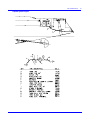
1
J/46 Owner Guide
COPYRIGHT J/BOATS, INC., 1999-2000
J/46 OWNER GUIDE 2
Table of Contents
Specifications ......................................................................................................................................................... 4
Important Contacts .................................................................................................. Error! Bookmark not defined.
Commissioning Checklist..................................................................................................................................... 6
Getting Started With Your J/46............................................................................................................................. 7
J/46 Steering System ............................................................................................................................................... 8
Sail Control Systems ................................................................................................................................................ 9
Diagrams, Layouts, & Schematics .................................................................................................................... 11
Mainsheet & Traveler Diagram .............................................................................................................................. 11
Halyard Layout........................................................................................................................................................ 12
Reefing System Diagram ....................................................................................................................................... 13
Engine & Optional Generator Layout..................................................................................................................... 14
Fuel System Layout................................................................................................................................................ 15
Deck Fill & Thru-Hull Locations.............................................................................................................................. 16
Fresh Water System Layout .................................................................................................................................. 17
Sump Layout........................................................................................................................................................... 18
Bilge Pump Layout.................................................................................................................................................. 19
Main AC/DC Distribution Panel.............................................................................................................................. 20
AC/DC Component Layout .................................................................................................................................... 21
Standard DC Wiring Schematic............................................................................................................................. 22
Optional Inverter Wiring.......................................................................................................................................... 24
Propane System Layout......................................................................................................................................... 25
Bonding System...................................................................................................................................................... 26
Keel Installation Instructions................................................................................................................................... 27
Tuning The Rig ..................................................................................................................................................... 28
Engine System...................................................................................................................................................... 29
Drive Train............................................................................................................................................................... 29
Fuel System ............................................................................................................................................................ 30
Engine Cooling System .......................................................................................................................................... 30
Exhaust System...................................................................................................................................................... 30
Engine Safety Precautions..................................................................................................................................... 31
Starting The Engine................................................................................................................................................ 31
Engine Maintenance............................................................................................................................................... 33
Plumbing Systems ............................................................................................................................................... 34
Fresh Water System .............................................................................................................................................. 34
Thru-Hulls................................................................................................................................................................ 34
Pump Systems ....................................................................................................................................................... 34
Head System .......................................................................................................................................................... 35
Electrical System.................................................................................................................................................. 35
DC Electrical System.............................................................................................................................................. 35
110 VAC Shorepower System ............................................................................................................................... 36
Galley Stove LPG System...................................................................................................................................... 37
Safety...................................................................................................................................................................... 38
Maintenance Tips ................................................................................................................................................. 39
Annual Maintenance Checklist........................................................................................................................... 41
Storage Tips .......................................................................................................................................................... 42
Attachments & Enclosures:
•
Important Hall Spars Carbon Mast Information
•
TPI Compostites Limited Warranty
J/46 OWNER GUIDE 3
Introduction
WELCOME ABOARD and welcome to the J/Boats family of owners. Your boat is designed and engineered to be
the strongest, best performing, easiest-to-use, and most comfortable sailing boat of its type.
Sailing involves risk, most of which can be minimized with advance planning and proper seamanship. The J/46
owner should become proficient in all aspects of handling the vessel under sail and power, and be well versed with
emergency procedures before undertaking any offshore passage. The owner is further responsible for any required
state registration or federal documentation, accident reporting, outfitting the vessel with proper safety equipment,
and the safe operation of the vessel. J/Boats is happy to refer the owner to Boating Safety Courses or other
seminars available.
This guide is prepared to help owners understand proper rigging, tuning, and operation of the J/46. Please be sure
to complete the enclosed warranty card and mail to TPI Composites, Inc.
This guide is furnished for your benefit, but shall in no way be construed as any sort of warranty or contract, express
or implied, creating any obligation on the part of J Boats, Inc., with respect to any fact or facts or any advice or
opinions contained herein. The sole and exclusive warranty of the product is the TPI Composites, Inc. Warranty
described in the appendix hereto and on the Warranty Card furnished with the yacht. J/BOATS, INC. HEREBY
DISCLAIMS ANY AND ALL WARRANTIES, EXPRESS OR IMPLIED, INCLUDING ANY WARRANTY OF
FITNESS FOR A PARTICULAR PURPOSE OR ANY IMPLIED WARRANTY OF MERCHANTABILITY.
J/46 OWNER GUIDE 4
Specifications
LOA
46.0'
LWL
40.5'
Beam
13.8'
Draft
Ballast
Ballast Type
4.75’, 6.2' (std.), or 7.5'
9,500 lb. (std.), 8,900 lb. Deep
Cast lead strengthened with antimony
Displacement (std boat)
24,400 lbs.
100% Sail Area
1,020 sq ft
I
58.5'
ISP
60.5’
J
16.7'
P
53.5'
E
19.9'
Engine
Fuel Capacity
Engine Alternator
Battery Capacity
Water Capacity
Yanmar 76HP Turbo Diesel (4-cylinder)
90 US gallons
Balmar 150 amp
486 amp hours (add'l 210 amp optional)
120 US gallons
Interior Cabin Headroom
6.33’
Limit of Positive Stability
130+ degrees
Ice Box Capacity
LPG Capacity
Hull & Deck Core Material
Hull & Deck Molding Process
Hull Blister Warranty
Mast Height Above Water
10 cubic feet in two separate boxes
(2)10 lb. Bottles
Baltek AL-600 CK-57 End-Grained Balsa
SCRIMP Resin Infusion
10 Years: Owner Transferable
65.0'
J/46 OWNER GUIDE 6
Commissioning Checklist
Pre-Launch
Engine Start
___ Read equipment owner manuals
___ Read engine owner’s manual
___ Pre-rig mast and check installation of:
___ Align engine and shaft
•
halyards
___ Start engine
•
blocks
___ Check exhaust for cooling water flow
•
electronics
___ Check oil press., water temp., charging gauges
•
shrouds
___ Check transmission- forward/reverse
•
spreader chafe guards
___ Check shaft seal
•
lifeline pins
Step Mast
___ Pre-rig boom
___ Remove interior headliner at mast opening
___ Bottom painted or touched up
___ Hoist spar and lower into boat
___ Check propeller/strut/zinc
___ Attach furler to stemhead fitting
___ De-winterize engine and check status of:
___ Attach hydraulic cylinder to backstay and plate
•
engine oil/ filter
___ Attach all shrouds and hand tighten
•
coolant level
___ Install wedges/Spartite and mast boot
•
transmission fluid level
___ Connect mast junction box wires
•
water intakes/filter
•
fuel lines/filter
Rigging
___ Install boom
___ Check battery charge
___ Lead all halyards to stoppers on cabin top
___ Align prop vertically & mark shaft
___ Rig reef lines
___ Check all hose clamps, tighten as required
___ Install and connect boom vang
___ Close all seacocks
___ Rough tune spar per tuning guide
Loose Gear
Systems Check
___ Fenders and lines
___ Fill water tanks- flush twice to eliminate anti-freeze
___ Dock lines
___ Check water pressure system, bleed air if necessary
___ Winch handles
___ Fill and check LPG system
___ Ignition keys
___ Fill fuel tanks
___ Bilge pump handles
___ Check operation of electrical systems and pumps
___ Mast wedges/Spartite lubed
___ Check sailing electronics
___ Double-check sling locations and mark
Launch
Trial Sail
___ Raise and lower sails to check for fit
___ Check for leaks
___ Monitor engine performance and check shaft seal
___ Check seacocks
___ Check bilge for leaks
___ Check shaft seal for leaks
___ Check sailing electronics
___ After sailing, re-caulk main chainplates
___ Mark locations in cockpit to install teak foot braces
(shipped loose)
J/46 OWNER GUIDE
7
Getting Started With Your J/46
Generally, your dealer or commissioning yard will help you prepare your boat before launching. And in
most instances with a boat this size they will undertake the entire commissioning job. They are experts in
the field and are capable of completing most commissioning tasks.
Before Proceeding
Before you begin to assemble your new boat you should become familiar with the different sail control
systems and associated hardware. All running rigging and loose deck hardware items are shipped from
the factory in parts boxes complete with part inventory sheets. To help you properly install these items
please refer to the rigging and hardware sections and diagrams in this guide.
The Commissioning Checklist: will help you double check that the J/46 is assembled properly and all
systems and rigging are functioning properly. If a boat yard other than an authorized J/Boat dealer is
performing the work, review this list with them to establish what needs to be done and by whom.
Topsides: wash off all dirt and grime accumulated from delivery. Use only non-abrasive cleansers on the
gelcoat. Then apply a coat of high quality car or boat wax or use a synthetic poly-based coating. Either
finish will prolong the life and sheen of the gelcoat.
Bottom: preparation is critical to long-lasting enjoyment. To ensure a professional finish, carefully review
the paint manufacturer’s recommendations for preparing the bottom and have your dealer to roll it or spray
it on. Be sure that there are a minimum of 4 coats of epoxy primer covering the keel and rudder prior to
final coating of bottom paint.
Chainplates: are custom built of polished 316 grade stainless steel. Each pair surrounds the 1-1/2”
fiberglass main structural bulkhead and is anchored directly to it with staggered bolts. The backstay
chainplate is also 316 grade and through bolts directly to a reinforced area of the transom.
Stemhead Fitting: is a custom polished 316 grade stainless fabrication with integrated bow roller and
anchor retainer pin. The stem head fitting is designed to withstand all headstay loads, and is attached with
bolts directly to the stem of the hull.
Mast Collar: is built of polished 316 grade stainless and incorporates welded rings for halyard and reefing
line blocks and a forward halyard bar. The mast boot fits over the flange of this collar to seal the interior.
Toe Rail: is extruded and anodized aluminum 2” in height which is installed along the entire length of the
boat and through bolted to the hull/deck joint at six inch intervals. Accommodations for amidships, bow, &
stern chocks and cleats are also integrated into this toe-rail.
Stanchions & Pulpits: are designed for proper offshore safety as well as to facilitate access to the boat.
Included are two lifeline gates to port and starboard and a stern boarding gate. The bow pulpit is properly
braced, houses the bow running lights, and with a mid-height bar across the front end. The stern push-pit
is standard with an aft gate and stern running light. This is a convenient place to mount a man overboard
module, outboard bracket, etc.. All stanchions are 1” diameter tapered stainless steel and are secured into
their custom designed bases with machine set screws.
Lifelines: are SS wire in accordance with ORC safety regulations and are fastened at either end by
stainless forks and turnbuckles. Each lifeline is clearly marked from the factory and is intended to fit a
specific portion of the lifeline/stanchion system. The installation follows:
J/46 OWNER GUIDE
8
•
Insert all lifeline gates/stanchions into the sockets provided along the toe-rail. Secure each stanchion
in place by tightening the two set screws in each base. We recommend that you dip the screws in
blue Loctite or sealant before securing, so they don’t work themselves loose over time.
•
Install all lifelines without tightening the turnbuckles. Remove the eyes at the ends of the lifelines and
thread them through in the stanchions.
•
Finish off the job by tightening the turnbuckles, adjusting the lifeline gate pendants for the proper
length, and taping off the turnbuckle “split rings” (or cotter pins) for a finished appearance.
Skylight Ventilation Hatches: are made of extruded anodized aluminum frames (polished frames are
optional) and scratch-resistant acrylic covers. Each hatch comes equipped with a ventilation position and
180 degree articulation.
Ports and Opening Ports: are of painted aluminum frames with bronze colored acrylic and arrive “readyto-use”. The opening ports are specifically engineered and located to maximize cross-flow ventilation.
DO NOT PERMIT ACETONE OR OTHER HARSH CLEANSERS TO GET ON PORTS, OR HATCHES
AS THEY MAY DAMAGE THE FINISH & CLARITY OF SOME DECK HARDWARE.
Dorade Ventilators: The J/46 is equipped with four dorade ventilators which supply air to the forward and
main cabins. The forward ventilators (near the mast) are each protected by a stainless deck guard. Flat
plates (provided in a ship loose kit) can be screwed down with the dorade guards to close off the outside
air supply.
Deckhouse Handrails: Built of 316 grade stainless these replace the traditional teak to facilitate easy of
maintenance and ownership.
Winches: Standard winches are all-chrome self-tailing models from Lewmar Marine. The location of the
winches facilitate sailing with one or two aboard. Each is geared to match the load requirements of the
specific task.
Windlass: The J/46 is equipped with the Lewmar Concept windlass for simple anchoring operation.
Please refer to the windlass manual for specific operating instructions.
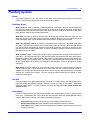
J/46 Steering System
The steering system is carefully engineered to provide finger-tip control. This is achieved by utilizing
Harken rudder bearings and steering system components from Edson. The pedestal is custom fabricated
by TPI to incorporate the 5” Ritchie compass, engine throttle, and additional instrumentation.
Wheel: is a 60” Edson “Diamond” series wheel with an Elk hide cover. The wheel is mounted to the
pedestal by through-bolting the hub to the stainless hub bracket. When installing, first center the rudder,
then install the wheel with the name plate vertical. Then place a mark at the top of the rim or on the vertical
spoke as a centerline reference point.
Rudder: is made of unidirectional glass, with two halves bonded together, and a highly reinforced
fiberglass shaft which extends to 80% of the depth of the rudder. The rudder is engineered to withstand
tremendous shear loads in ocean conditions. It’s high aspect shape helps reduce the “torque” tendency of
most rudders, thereby reducing helmsman and auto-pilot fatigue.
J/46 OWNER GUIDE
9
Rudder Stock Stuffing Box: is located at the top of the fiberglass rudder tube beneath the decks. It is a
simple design which prevents water from entering the hull. A stainless sleeve bearing surface surrounds
the rudder tube at the point where a rubber seal is forced against it to prevent water from rising up the tube.
Emergency Tiller: is operated by lifting off the access plate (amidships), and placing the base of the tiller
over the head of the rudder stock. Then secure a line (any spare line or dock line) to each eye at the end
of tiller, and lead outboard through the spinnaker sheet turning blocks, forward to either the mainsheet or
primary winches. If you pull the starboard line the boat turns to port. Pulling the port line steers the boat to
starboard. Fit the emergency tiller NOW to see how the system works BEFORE you get caught in a
situation where you won’t have the time!
Sail Control Systems
The J/46 sail control systems are designed for maximum efficiency and ease of handling. Below is a brief
description of each system:
Mainsail Controls:
Main Halyard: exits the mast on the port side, runs through a turning block at the mast collar aft to the
organizer and then aft to the rope clutch leading into the cockpit halyard/secondary winch.
Main Sheet: is a 2:1 continuous system running to both port and starboard side mainsheet winches. The
line is led from one winch through a deck mounted turning block to one block on the traveler car, up to the
single boom block, back down to the second block on the traveler car, and out to the other deck block and
finally to the other winch. The system is designed to allow extremely easy adjustments of the mainsheet by
any size or age person. The self-tailing winch feature also facilitates single-handed sailing and rapid
adjustments during sailing maneuvers. Be sure to put a “stopper knot” like a figure-eight at both ends of
the sheet.
Traveler: consists of a traveler bar and traveler car mounted in the cockpit. The car is controlled by a 6:1
purchase system led to either side of the cockpit. The traveler control line dead-ends outboard at the base
of the end car system, then runs back and forth between the traveler car and end fitting, finishing at the
cleat assembly.
Reef Lines: are designed to be fully functional from the cockpit. The mainsail tack reef lines lead from a
pad-eye on the side of the mast below the gooseneck, up through the tack cringle in the mainsail, and back
down through a cheek block mounted on the opposite side of the mast, down through a mast collar turning
block, then aft to a cockpit cabin top winch. The mainsail clew reef lines exit the forward end of the boom,
lead aft through the mast collar turning block to the cockpit cabin top winches.
Outhaul: is an 12:1 internal tackle system pre-assembled by Hall Spars and cleated underneath the
boom.
Boom Vang: is manufactured by Hall Spars and is equipped with a Harken block and tackle system. The
block with the integral cleat should mount to the lower end of the vang. Adjust the support spring by
removing the large Allen screws on either side and align in the proper adjustment hole per the Hall
instructions.
Backstay: A Sailtec integral hydraulic backstay adjuster is included with the J/46 to enable you to control
the upwind shape of the mainsail by bending the mast. A simple hand pump and release valve control the
operation of this unit.
J/46 OWNER GUIDE
10
Jib Controls
Jib Halyard: exits the mast on the port side, runs through a turning block at the mast collar aft to the
organizer, and then leading into the halyard/secondary winch.
Jib Sheet: is attached to the headsail by a bowline knot and led aft to the jib car on the jib track then aft
through the foot block to the primary winches. If a large genoa is used, the sheets lead outboard of the
shrouds to the aft genoa car, then through the foot block and to the winch.
Jib Blocks & Tracks: are located port and starboard along the cabin sides. Adjustable pin stop jib/genoa
lead blocks are supplied for the main track with two snatch blocks provided for use on outboard jib tracks.
Spinnaker Equipment
Spinnaker Halyard: exits the starboard side of the mast and leads through a turning block at the mast
collar to an organizer block and then aft to the clutch.
Spinnaker Sheets: lead from the clew of the spinnaker aft outside the lifelines through the spinnaker
sheet blocks (just in front of the stern pushpit), forward through the deck cheek blocks, then to either the
cabin top or primary winches. When hooking up the asymmetrical spinnaker the windward (or lazy) sheet
should be led in front of the headstay.
Tack Line: The tack line leads through the Harken 75mm block on the forward-upper hole of the bowroller and then aft to a rope clutch at the cockpit.
Snuffer Control Loop: Assuming you have ordered a snuffer with your spinnaker, there are two ways of
rigging the snuffer control lines. 1) Leave them loose on the foredeck, and once the spinnaker is raised
and “unsnuffed” you can pull the slack out of both snuffer lines and secure at the mast base. Snuffing the
spinnaker then requires you to go to the foredeck. 2) Run the control lines through two small blocks
(shackled on either side of the tack line block) aft along the starboard side to two Harken cleats mounted
on the starboard side of the cabin trunk. The upper cleat is intended for the control line that raises the
sock, the lower cleat for the line that lowers the sock. The loop is continuous so you must uncleat both for
the system to function. There is more friction with this system, but you are able to snuff the spinnaker
without leaving the cockpit.
J/46 OWNER GUIDE
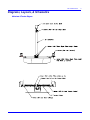
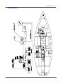
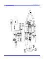
Diagrams, Layouts, & Schematics
Mainsheet & Traveler Diagram
11
J/46 OWNER GUIDE
Halyard Layout
12
J/46 OWNER GUIDE
Reefing System Diagram
13
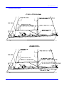
J/46 OWNER GUIDE
Engine & Optional Generator Layout
14
J/46 OWNER GUIDE
Fuel System Layout
15
J/46 OWNER GUIDE
Deck Fill & Thru-Hull Locations
16
J/46 OWNER GUIDE
Fresh Water System Layout
17
J/46 OWNER GUIDE
Sump Layout
18
J/46 OWNER GUIDE
Bilge Pump Layout
19
J/46 OWNER GUIDE
Main AC/DC Distribution Panel
20
J/46 OWNER GUIDE
5 AMP
FUSE
AC/DC Component Layout
21
2/0 RED
WINDLASS
125 AMP
BREAKER
AGM 4D
210 AMP HR
HOUSE BANK 1
2/0 RED
2/0 BLACK
10 AMP
8 GA BLACK
100 AMP
BREAKER
MAIN
DISTRIBUTION
PANEL
2/0 BLACK
} BATTERY TEMP SENSE - NOT USED {
Both
AGM 4D
210 AMP HR
OPTIONAL
PRESET PROGRAM
PROGRAM MODIFY
#1/#2/Both/off
SWITCH
ALARM AND / OR LAMP
SPLICE INTO YANMAR HARNESS
BLUE / BLACK WIRE
}ALTERNATOR TEMP SENSE {
16 GA BLACK
Batt/Maxx
BATTERY
PARALLEL
SWITCH
TO BUZZER
AGM
M 1000
56 AMP HR
ON/OFF
SWITCH
F
S
B
YANMAR
4JH
R
ALTERNATOR
Standard boat
J46 Battery
Schematic
Rev.F
STARTER
MOTOR
150 AMP
ENGINE BATTERY
CHARGE LAMP
IGNITION SW
ENGINE PANEL
2nd BLACK (-) GROUND
2/0 RED
AGM
31 LIFELINE
105 AMP HR
HOUSE BANK 2
AGM
31 LIFELINE
105 AMP HR
2/0 RED
DATA OUT- NOT USED
8 GA RED
MC-512
16 GA BLACK
BLACK (-) GROUND
2/0 RED
RED (+) BATTERY SENSE
2/0 RED
BLUE (+) FIELD
2/0 RED
BROWN (+) SWITCHED
J/46 OWNER GUIDE
Standard DC Wiring Schematic
22
J/46 OWNER GUIDE
AC Component Layout
23
J/46 OWNER GUIDE
Optional Inverter Wiring
24
J/46 OWNER GUIDE
Propane System Layout
25
J/46 OWNER GUIDE
Bonding System
26
J/46 OWNER GUIDE
Keel Installation Instructions
NOTE: INSTALLATION OF THE KEEL SHOULD BE PERFORMED BY
AN EXPERIENCED BOAT YARD. INSTALLATION MAY REQUIRE
MODIFICATION TO SUIT AN INDIVIDUAL BOAT YARD'S PRACTICES.
DEVIATION FROM THE PROCEDURE DESCRIBED BELOW SHOULD BE REVIEWED
WITH TPI CUSTOMER SERVICE. TEL: (401) 247-1050 OR FAX: (401) 247-4115
STEP BY STEP PROCEDURE
1)
2)
3)
4)
5)
6)
7)
8)
9)
10)
11)
12)
13)
14)
15)
16)
17)
APPLY A THIN FILM OF GREASE OR MOLD RELEASES WAX TO AFT 2 BOLTS.
DRY FIT KEEL TO HULL.
LIFT HULL APPROXIMATELY 5" ABOVE KEEL.
ROUGH UP TOP OF KEEL SURFACE AND HULL SUMP SURFACE.
COVER TOP OF KEEL WITH 3M 5200 SPREAD EVENLY OVER ENTIRE SURFACE.
LOWER HULL TO KEEL, 3M 5200 SHOULD
SQUEEZE OUT AROUND PERIMETER. (clean up excess)
CHECK TO SEE IF KEEL IS SET VERTICALLY BY
MEASURING FROM KEEL CENTER LINE TO HULL SHEER BOTH
PORT AND STDB. SHOULD MEASURE THE SAME AT THE TRAILING EDGE
AND LEADING EDGES OF KEEL AT TOP AND BOTTOM.
WHEN KEEL FITS PROPERLY INSTALL THE 4 FWD KEEL
WASHERS BED THEM WITH 3M 5200.
INSTALL NUTS AND TIGHTEN SNUG.
2 AFT BOLTS FILL GAP BETWEEN TUBE AND BOLT WITH GP RESIN
MIXED WITH MEKP HARDENER (NO ADDITIVES) TILL FLUSH WITH INSIDE OF HULL SUMP.
LET CURE 2 HOURS.
INSTALL AFT 2 WASHERS BED IN 3M-5200.
TIGHTEN ALL THE 1 1/4 NUTS TO 450 FT.LBS TORQUE
LET CURE 24 HOURS. THEN PAINT INSIDE SUMP AREA WITH AIR DRY GEALCOAT.
APPLY 1708 TABBING AROUND RABBET W/ EPOXY RESIN. (APPROX. 2 LAYERS)
SAND AND FAIR WITH VE PUTTY OR EQUIVALENT EPOXY FAIRING PUTTY.
WARNING: DO NOT REMOVE OR SAND THROUGH FACTORY GRAY EPOXY COAT
APPLY BOTTOM PAINT AS INSTRUCTED BUY THE PAINT MANUFACTURER'S
RECOMMENDATIONS.
MATERIALS
1 #48023 or #48081 KEEL
6 #48085 WASHERS
2 #29030 3M 5200 TUBE
6 #42060 NUT 1-1/4"
#47037 CLOTH 1708 X 6" WIDE X 32 FT.
#46142 MEKP
#46206 GP RESIN
#46003 H31 CATALYST
#46141 EPOXY RESIN 37-139
#46190 PUTTY VE, CHOP
MIXING INSTRUCTIONS
GP RESIN
EPOXY
GP RESIN 33-234-01 (1 QUART)
TO MEKP CATALYST (10 cc)
EPOXY RESIN 37-139 (1 GAL)
TO EPOXY CATALYST H-31 (2 QUARTS)
2:1 RATIO
27
J/46 OWNER GUIDE
28
Tuning The Rig
Tuning the Mast
Please refer to special manufacturer instructions for the optional Hall carbon fiber mast included at the end
of this guide.
•
The standard headstay length is designed to allow sufficient rake for good upwind balance with
either small or large jib. The Harken MK III Unit 2.0 furler fits the standard –17 rod headstay. The
backstay is set-up with a toggle under the hydraulic cylinder to set the handle forward and the
release knob aft. The mast step has a small range of adjustment.
•
After the mast is in a Spartite kit has been provided in order to support the spar completely at the
deck. Please follow the installation instructions from Spartite to install properly. After the Spartite
sets, add a large bead of silicone around the mast to eliminate incremental wicking of moisture
belowdecks.
•
After taking up the upper and lower shrouds hand-taught to center the mast (using the main
halyard to equalize distance to the port and starboard rail), apply maximum backstay on the
cylinder to bend the mast.
•
Tighten the upper shrouds equally to port and starboard with a wrench.
•
Release the backstay and tighten the lower shrouds to straighten the mast and establish the
correct amount of pre-bend recommended by your sailmaker
•
The middle section of the mast is held in place laterally by intermediate shrouds which attach to
the mast below the upper spreaders and terminate at the deck. Each are adjusted with
turnbuckles. Most people tend to over-tighten these on their first try.
•
Double check your tuning handiwork by looking up the backside and front side of the mast to be
sure that it is straight from side to side.
•
Go sailing in 12-14 knots of wind with 80-90% backstay pressure. Chances are your leeward
upper shrouds will look loose. If so, take up on the leeward upper 2-3 turns, then tack and adjust
the other upper shroud the same. Continue back and forth until you’ve eliminated any visible slack
in the leeward upper shroud. Release backstay to medium pressure, site up the mast to check
side-to-side straightness, and then tighten the leeward lower shrouds as necessary to straighten
the side to side. You’ll probably find the lowers will only need 1 or 2 turns beyond hand-tight for the
right setting. Too much and you’ll see the mast bow to windward at the lower spreader.
•
Check straightness and repeat the process making minor correcting adjustments to leeward
rigging only. Pin and tape the shrouds when finished.
Rigging The Boom
st
Run the single line 1 clew/tack reef from the clew to the forward end of the boom, up through a sheave on
the boom, to an individual turning block attached to a SS hook (this hooks into tack reef grommet in sail).
This line then leads down to the turning block at the mast collar, through the organizer and aft to a rope
nd
clutch. The 2 clew reef line leads in a similar fashion but exits the boom down to the mast collar block
then aft.
•
Attach boom gooseneck to lug on mast with large clevis pin.
•
Attach Quik-Vang to mast lug at deck and then boom lug (hoist end of boom with main halyard if
necessary).
•
Install mainsheet block (Harken 100mm) on bail at end of boom.
•
Install mainsheet per rigging diagram.
J/46 OWNER GUIDE
29
Engine System
The engine and fuel system is engineered to be conveniently accessible for repairs and general
maintenance. Located aft of the companionway ladder. There is access to the front, sides and back of
the engine from which all important functions can be reached; including water strainer, fuel injectors, fuel
filter, fuel primer, expansion chamber, and alternator.
Before starting the engine read the engine manufacturer’s owner’s manual for proper break-in and
operating procedures. Once the engine is running, inspect it for any discrepancies, like oil leaking,
excessive water leaks, or anything out of the ordinary.
•
Engine Control Panel: is mounted aft of the port side of the helmsman’s cockpit. It contains the
starter, kill switch, warning lights, and gauges. The combination throttle/gearshift are mounted on the
steering pedestal. Double-check all mechanical connections between engine and on-deck equipment.
•
Engine Bed: is constructed of heavily reinforced fiberglass. This provides a superior mount over
wood and is also rot-proof. The engine sits on Yanmar “soft” rubber shock mounts to help isolate the
engine vibration from the boat. Check to see that the engine is sitting correctly on them and the bolts
tightly secured.
Drive Train
This is the complete system which propels your boat. It includes the following components; coupling, selfaligning thrust bearing, shaft seal, shaft log, shaft, strut, and the propeller.
•
Transmission: is attached to the aft end of the engine and houses the reduction and reverse gears.
These gears generally need little maintenance, but the oil level should be checked periodically.
•
Shaft Seal: is aft of the engine where the propeller shaft passes through the hull. It is a waterproof nodrip Volvo shaft seal. Please refer directly to the owner manual for this component for more
information.
•
Max Prop Feathering Propeller: is a geared feathering propeller built of high quality bronze alloy.
Check to see that the blades on the prop open almost perpendicular to the shaft. There are a few
easy precautions which can prolong its life:
1) Coat it with a silicone grease film.
2) Check to see that the joints in the folding prop have a good coating of waterproof grease.
3) Check that the blades are smooth.
•
Propeller Shaft: is stainless and supported at the inboard end by the shaft coupling and at the
outboard end by the bronze cast strut containing a “cutlass bearing.” Before launching attach a “shaft
zinc” to minimize corrosion. The zinc should be replaced each time the boat is hauled and perhaps
more often depending on the amount of active current in your home port.
•
Engine/SHAFT Alignment: is set by TPI to ensure that the engine, shaft, stuffing box, and prop are
properly adjusted to minimize engine vibration. During commissioning, the alignment should be realigned, as it is difficult to duplicate actual conditions (in the water with rig tuned) in the factory. If there
seems to be excessive vibration, notify your dealer and have them investigate.
J/46 OWNER GUIDE
30
Fuel System
•
Fuel Tank & Hoses: The J/46 is equipped with two fuel tanks for a total 90gallon capacity. The
primary 60gallon tank is located under the quarter-berth. A secondary tank is located on centerline aft
below the steering cables. This 30gallon tank gravity feeds into the primary tank. Fuel lines run from
the primary tank to the fuel primer pump. From there fuel flows into the injectors. The tanks
themselves are aluminum and baffled to prevent fuel slosh. The secondary fuel tank is designed to
allow conversion to accommodate an optional generator and/or heater. For a layout, please see the
Fuel System diagram.
•
Fuel Gauge: is located under the wheel hub at the pedestal. The gauge reflects level (height) of fuel
in the primary tank, not the quantity. Try to maintain a minimum level of 1/3 to 1/2 tank filled at all
times.
•
Fuel Line Shut-Off Valve: also sits atop the tank at its forward end. Since diesel engines require
bleeding after they have been deprived of fuel, it’s important that the shut-off valve be in the “ON”
position (lever parallel to piping) anytime the engine is started.
•
Fuel Tank Access Plate: is atop each fuel tank and provides access inside to clean the tank or check
the fuel gauge.
Engine Cooling System
The engine utilizes a closed system in which a mixture of water and anti-freeze is circulated within the
engine for cooling. This liquid is cooled by a heat exchanger which uses sea water, in a similar fashion to
the radiator on a car which uses air to cool the contained liquid.
•
The filler cap for the fresh water (closed) cooling system is located on top of the engine manifold, and
looks like a radiator cap. Check the level in the manifold frequently (ensure engine is cool). If
additional liquid is necessary, add only a mixture of anti-freeze/fresh water. In colder climates where
freezing may occur over the winter, be sure to test the coolant anti-freeze/water mixture for freezing
point and add anti-freeze as needed if the system is not drained for winter lay-up. Follow engine
manual recommendations for proper water/anti-freeze ratios.
•
The WATER STRAINER is located in the engine compartment and has a two-stage design to prevent
“clogging” of the cooling system. Its simple design facilitates periodical cleaning. To clean: Ensure the
engine water intake thru-hull is closed. Check that the lever is perpendicular to the intake. Unscrew
the wing-nuts atop the filter and remove the strainer from inside the glass case. Wash thoroughly with
water or replace with a new one if badly soiled. Replace strainer into case and tightly affix lid with the
wing-nuts.
Exhaust System
The J/46 is equipped with a water-injected exhaust system which cools the exhaust. It is designed to both
dissipate heat and act as the exhaust muffler. If the flow of cooling water is interrupted and the engine
overheats severely, the rubber hose coming from the engine exhaust elbow may melt. Always check this
hose after an occurrence of overheating. Water can accumulate in the bottom of the muffler. In fall decommissioning, the pot should be drained using the drain plug, or anti-freeze added to the pot so residual
water doesn’t freeze. If the engine does not start after a prolonged period of cranking over (starting), be
sure to drain the pot or exhaust loop. Water accumulates here and may fill enough to flow back into
engine manifold if engine does not start.
J/46 OWNER GUIDE
31
General Hints To Avoid Problems
•
Monitor brightness of cabin lighting and charge batteries as required by running engine. Batteries are
charged by either the AC battery charger or by running the engine.
NEVER START THE ENGINE WITH SHORE POWER CONNECTED
•
Stop engine with throttle fuel cut-off, then turn ignition key “off”.
•
NEVER turn engine battery switch to OFF position while engine is running.
•
For best efficiency and fuel economy a cruising R.P.M. of 2,600 -2,800 works well. Vary RPM levels
periodically when cruising under power for a long distance. Be sure to thoroughly read and follow the
manufacturer’s manual for proper break-in procedure for the standard turbo charged Yanmar Diesel
engine. Remember, that a turbo engine is designed to run at higher RPMs (over 2,000) and not to be
used at idle speeds for long periods of time, which will soot up the turbo. When not underway, battery
charging and refrigeration cooling should be handled via shorepower or an auxiliary generator.
•
Do not run engine at full throttle (3600 RPM) for sustained periods, as breakdown may occur. Most
importantly, find an RPM that runs smoothly and follow the Yanmar guide. Avoid "vibrating" RPM
speeds when possible.
•
Mark the shaft at the coupling where blades are vertically aligned causing least resistance when motor
is stopped and in neutral. Turn shaft by hand to “feather” prop then lock by putting gear shift in
“REVERSE”.
•
Keep engine gear shift lever in "REVERSE" position while sailing to prevent possible "free-wheeling" of
shaft.
•
CAUTION: The J/46 engine is very quiet, and it is possible to forget that it is running. Before shifting
the gear shift lever into REVERSE when sailing, double check that the engine is turned off.
Engine Safety Precautions
Due to high temperatures it is recommended that after running the diesel for more than two hours you
reduce speed to idle and allow excess heat to dissipate for five to ten minutes.
The most common cause of trouble is contaminated or dirty fuel. Your boat is equipped with a dual
primary fuel filter located in the engine compartment and a secondary filter on the engine. The wise
skipper carries replacement filter cartridges. The dual filter is designed so that one filter is in operation
while the other is a spare. This way you can switch the fuel flow through the spare filter, if you need to
change out the first one.
Familiarize yourself with the bleeding procedure for the engine and try bleeding it yourself. The procedure
only takes a few minutes after you are acquainted with it, but can be exasperating to the uninitiated.
Starting The Engine
•
If installed, turn VHF, GPS and Instruments "OFF."
•
Transmission lever:
FORWARD=
PushForward
J/46 OWNER GUIDE
NEUTRAL=
Between Forward & Aft
REVERSE=
Pull Aft
32
Push in throttle button at center of handle and move throttle lever forward 1/3 to increase initial starting
RPM's.
•
Turn ignition key to "ON" position. Audible alarm indicates low oil pressure, and will continue until
engine starts. There is an oil pressure alarm test switch on the cockpit engine panel.
•
Turn the ignition key to the "START" position. Release immediately after start. If it does not start in
ten seconds, turn off key. Advance throttle slightly and after ten seconds, repeat.
•
Oil pressure light and audible alarm should go out after starting. If not, stop engine.
•
Once engine starts, set throttle at about 1,000 RPM. Check for exhaust water. If no water, shut down
engine immediately. Check to be sure through hull valve to engine cooling system is open, or if the
sea water strainer is clogged. If indications are normal, warm up ten minutes.
•
Test forward and reverse at dock with docking lines in place. Shifting should be done below 650
RPM's AT ALL TIMES. Shifting at too high a speed will cause severe damage to the entire drive train.
•
Check for exhaust water periodically. Engine is cooled by sea water via a heat exchange and
enclosed fresh water system. Water temperature should be 165 degrees or less and water should exit
from the stern at all times. Without water exhaust discharge, engine will burn up.
•
The best cruising RPM is approximately 2,600-2,800 RPM. Maximum continuous rated RPM is 3400.
Check sea water strainer for debris. Ensure thru-hull is open. If necessary, check under hull to see if
intake is blocked.
•
It is best to keep fuel tank 1/2 full (diesel #2) to avoid debris intake and air locks.
Turning Engine Off
•
Place throttle lever in idle position (vertical).
•
Let engine cool down.
•
Push engine stop button on engine instrument panel until engine stops.
•
When audible alarm sounds, turn key off. DO NOT use key to stop engine. Do not stop engine with
decompression lever except in extreme emergency. If decompression lever is used to stop engine,
fuel will spray out and accumulate on top of pistons, creating danger of explosion the next time engine
is started.
•
When under sail you may hear propeller "wind milling" underneath. After shut down put engine in
reverse gear and it will stop. Because the J/46 engine is so quiet, make double sure the engine is off
before switching into reverse gear.
Fueling the Diesel Tanks
When preparing to take on fuel, the following safety precautions should be followed at all times: Properly
secure the boat to the dock using bow, stern and spring lines.
J/46 OWNER GUIDE
33
•
Shut off all equipment: Engine, Battery Switch, Radios, Lights, Etc.
•
Remove fuel fill plug and clean threads of both plug and deck plate carefully so no dirt falls into filler
opening. Place the fuel hose nozzle into the fill pipe.
•
Fill slowly. DO NOT OVERFILL. Marine fuel expands with an increase in temperature. Thus, fill only
to 95% capacity. If you cannot see the fuel pump, ask the attendant or a crew member to call out the
total gallons. l.
•
If fuel tank is overfilled, fuel will leak out the tank vent located on the transom. This spillage should be
cleaned up immediately.
•
After fueling, replace fill plate and wash up any spillage. Go below deck and check for fumes or
leakage. Check bilge. IF EITHER FUMES OR LIQUID FUEL ARE PRESENT, CORRECT THE
SITUATION BEFORE PROCEEDING. Open all hatches and ports to facilitate ventilation.
•
Only after you are totally satisfied that no potentially dangerous condition exists, leave the fuel dock.
Be considerate of fellow yachtsmen.
•
In the event of a serious spillage, STOP FUELING IMMEDIATELY. Replace fill plate, notify attendant
so he may warn others and wash down thoroughly all traces of fuel or source of fumes.
Engine Maintenance
Check the engine, batteries, and engine mounts once a month. Ensure the engine is fastened securely to
the engine mount frames and look for any problems, such as fuel or oil spillage. If you need help, consult a
professional marine mechanic or a Yanmar licensed repair mechanic.
Run the engine frequently and at occasional high speeds, even if it is not in gear. One reason why sailboat
engines may burn out within a few years is that they are run infrequently and lubricating oil is not thoroughly
and evenly distributed on all moving parts. Be sure to check oil and coolant levels often. If you have any
doubts about the purity of the fuel you are buying, use a strainer to filter out water and dirt.
If there is excessive vibration, in other than specific RPM points, loosen the coupling and insert a feeler
gauge all the way around to determine if the engine is properly aligned. If aligned and vibration persists,
check prop for proper balance and uniform opening/closing and be sure that strut mounting is secure. If
there is still a problem, contact your nearest Yanmar Service Representative.
J/46 OWNER GUIDE
34
Plumbing Systems
General
The plumbing systems in your J/46 consist of fresh water, manual and electrical pumps, and the heads
(toilets). This section will describe their locations and how they operate.
Fresh Water System
Water Tanks: are made of rotationally molded polyethylene. Connected to them are the following hoses:
a) fill hose- is located on the tank top and connects to the deck water fill pipe; b) feed hose- located along
the tank bottom connects to the water system at the water selection Y valve; c) air vent hose is internal and
leads under the sheer line into the bow compartment.
Water Fills: are located on deck. Be sure the water cap threads are cleansed of dirt for a better seal. The
water may develop a “taste” after a long period of time. Instead of flushing it out you can add a commercial
water preservation agent, such as Sudbury Aqua Fresh crystals, to greatly improve the taste.
Water Tank Selection Y-Valve: is located on centerline below the cabin sole just forward of the galley
sink island. After the tank is changed, open a water faucet to allow air to escape. When the water trickles
out, close the faucet momentarily to allow the pump to build up pressure (check that it’s turned on!); then
open the faucet until a steady stream flows. It may be necessary to repeat the process several times to
bleed all the air from the system.
Water Pressure Pump: is located outboard and under the forward portion of the port settee berth in the
main cabin. The pump operates off the DC electrical system and pressurizes the entire water system.
Should any problems arise, read its manual. If the system is not pressurizing, first check that the pump is
working correctly, i.e. it’s pumping water. Secondly, check that all hoses are securely connected to their
fittings. Thirdly, ensure all air pockets are eliminated as outlined above. If there is still a problem, consult
your dealer.
Water Heater: is located under the “L” of the main cabin salon settee to port. Water is heated by either the
engine or shore power. If the water heater is on shore power, be sure a continuous supply of water is
available to it, otherwise the electrical element within it will burn out. Due to this potential risk, water heater
elements are excluded from warranty. Thus, be certain the water pressure pump is always on while
hooked up to shore power.
Thru-Hulls
All thru-hull fittings are of glass reinforced nylon or bronze. For safety reasons, we recommend that you
tape a soft wooden plug adjacent to all thru-hull fittings in the event of a hose or valve failure. These fittings
each have valve-handles. To reduce confusion, remember the long end of the handle indicates the
direction of flow.
Pump Systems
Pumps are easy to maintain and just as easily forgotten...they always happen to seize up when you need
them most. Consequently, take care to keep their screens clean and rubber gaskets/bellows working
correctly. Before taking a long trip, order replacement parts for all pumps.
•
Sink Drains empty directly overboard through a thru-hull fitting beneath each sink.
•
Shower Sump Pumps are locally operated in each head and drain directly overboard.
•
Icebox Drain valve is located under the bilge board and should be closed to keep in the cold air
except when draining.
J/46 OWNER GUIDE
•
35
Bilge Pumps are both electrical and manual. Two pump intakes are located in the keel stub
under the main cabin floor, with a third intake attached to a coiled hose in the aft head. This is
long enough to reach the bilge and qualifies under ORC cat 2.
•
The Manual pumps are operated from the cockpit and from the aft head.
•
Electrical Bilge Pump is wired to an independent switch on a recessed panel adjacent to the
nav station.
Head System
The J/46 is equipped with two certified marine heads which are capable of discharging effluents into a
holding tank or overboard. Both systems are easy to operate and with correct usage and proper
maintenance, will provide many years of use.
Before operating the HEAD, ensure you have read its manual thoroughly and understand the proper
procedures. Silly mistakes can cause severe “head” aches at the worst possible time! And a word to the
wise
PLEASE TRAIN YOUR GUESTS ON HEAD OPERATION. NEVER, NEVER ASSUME THEY KNOW
HOW TO USE IT!!
The head is a large pump which takes in seawater and flushes waste into the holding tank or overboard.
The salt-water intake thru-hull is underneath the head sink and the discharge is in the port aft locker.
Remember open/closed positions on these thru-hulls. It is good seamanship to close the intake and
discharge seacock for the head when not in use.
When seawater and effluent are pumped through the head, they’re pumped into the holding tank by the
action of pumping the toilet handle. The waste discharge fitting on deck is provided so a shoreside pumpout station (i.e. vacuum cleaner) can empty the tank. Care should be taken not to overfill the holding tank
as effluent can block the vent hose and may damage the tank... or worse, burst the hose. If the toilet is
difficult to pump, check to see if the holding tank is overfilled. “When in doubt, pump it out!”
The holding tank must be pumped out before winter storage. Dumping a quart of anti-freeze through the
heads will prevent the seals and equipment from cracking. For your information, the following hoses are
connected to the tank.
•
Waste Discharge Hose from the head
•
Pump-out Hose leading to the deck fitting
•
Vent Hose to vent the tank overboard.
Electrical System
The following section describes the electrical systems aboard the boat, how they operate, where they lead,
and how to avoid trouble. Please read this section over more than once. For wiring code information
please refer to the color code diagram.
DC Electrical System
A 12 Volt DC electrical system is used throughout the J/46 for lighting and operation of pumps and various
accessories. The J/46 is standard with one 210 Amp battery, two 105 Amp batteries, and one 56 Amp
1,100 CCA engine battery. An optional 210 amp AGM is available and replaces the lower nav station
drawer.
J/46 OWNER GUIDE
36
•
Electrical Panel: is built by Bass and controls electric distribution with circuit breakers and
switches. The main wiring harness runs from the back of this panel.
•
Mast Wiring Terminal Box: is located in the shower compartment on the bulkhead. A wiring
harness exits the mast near the box, and is wired directly into the D.C. system through a terminal
strip. Once this wiring is installed, test each function to insure proper operation.
•
Battery Switch: The battery switches (one for each house bank) are located under the navigation
table. They operate in either an ON or OFF position. The dedicated engine battery switch is
located in the aft cabin with a similar switch.
•
There is a waterproof Momentary Parallel Switch located in the cockpit at the engine panel. The
purpose of this switch is to allow you to start the engine using the house bank should the
dedicated engine battery fail.
•
The Alternator is attached to the engine and creates a charging current only when the engine is
running. The output is to an automatic battery system located in the aft hanging locker which
distributes the current to the batteries as deemed necessary.
•
Accessories: such as navigation instruments, stereos, radars, GPS can be added to the electrical
panel and the 12 VDC system. Extreme care and forethought is necessary for installation as these
are sensitive instruments and require some measure of protection. Such work should be performed
by a marine electrician. Be sure all sensitive accessories are not only grounded properly but that
“fast blow” fuses are run off the panel for extra insurance against damage to their components.
110 VAC Shorepower System
The 110 volt AC shore power system is functional only when the boat is plugged into suitable power from
shore. The cord provided as part of the option has the standard end for 50 amperage service. Depending
on the wiring in the facility, various adapters may be required to plug into the shore end. The boat end of
the cord plugs into the inlet on the starboard cockpit coaming. Ensure the plug prongs match those on the
inlet, insert and twist to lock it. Then screw down the outer ring to seal the cord from water and to prevent it
from pulling out. The AC panel for shore power is located in the nav station as part of the primary panel.
Due to the length of the wire run from the inlet to the electrical panel, there is a circuit breaker located aft of
starboard cabin bulkhead. This switch needs to be on in order for shore power to reach the panel.
•
AC Selector Switch: is located on the main electrical panel. This switch has settings for SHIP
service (inverter or generator) or, SHORE service (dockside). To activate AC power, use this
switch to select the source.
•
AC Side of the Panel: indicates line voltage being received from the shore circuit with an indicator
light. The line voltage will vary with the number of appliances operating on the same circuit. In
large marinas there may be a large number of boats on the same circuit, causing fluctuations
•
AC Normal/AC Reverse Polarity Light: The AC side of the panel has a red light to show when
the polarity is reversed. Care should be taken not to operate 110 AC systems on board with
reversed polarity. Double-check shore connections. If problems still persist, then notify dock
master to repair the shore plug. NOTE- Even though the switches are in the appropriate position,
the shore power system in no way assures personal safety using electrical apparatus.
•
Water Heater: switch supplies power to the water heater 110 AC element for hot water while
dockside. Note the precautions regarding the use of electrical power to heat water are contained
in the plumbing section of this manual.
•
Outlets: located throughout the cabin supply power for 110 AC accessories. The entire system
has “ground fault” protection.
•
Ground Fault Systems: There are two separate ground fault systems: 1) One in the nav station
to protect the outlets to starboard. 2) One in the galley protecting outlets to port.
J/46 OWNER GUIDE
37
Galley Stove LPG System
Liquid Propane Gas (LPG) is the most common fuel used for boating and is available at most marinas in
the U.S. The Force 10 stove is of very high quality and is engineered for the marine environment in highgrade stainless steel. It is comparable to a home range.
The biggest difference is safety. While the home gas stove utilizes a petroleum gas which is lighter than
air (it disperses easily if there is a leak), the propane stove utilizes a gas which is heavier than air, and thus,
sinks to the bottom of enclosed compartments. All J/Boats equipped with LPG stoves utilize a safety
system prescribed by ABYC and USCG guidelines. This includes an independently vented and sealed
compartment for the tank, an electronic solenoid shut-off valve, a regulator, and approved LPG hose.
•
Propane Tanks: are located in a specially designed compartment to starboard of the wheel in the
cockpit, which ventilates over the side to specifically eliminate the accumulation of dangerous
gases.
•
LPG Gauge: sits atop the tank to measure the amount of pressure left in the tank.
•
Solenoid Cap Valve: is located on the hose in the aft propane compartment. It electronically
shuts-off the flow of gas at the tank. This valve is a “normally closed” valve; therefore electrical
power must be provided so gas can flow to the stove.
•
Regulator: is located on the hose in the aft propane compartment. It is a screw down valve which
regulates the flow of propane into the system.
Stove Operation
•
Check that all burner (including oven) knobs are off.
•
Check manual valve on tank and open.
•
Ensure battery switch is on and 12 volt power available.
•
Turn on solenoid valve switch on electrical panel.
•
Open burner valve on stove slightly and light burner. Always apply flame or sparker to burner
before opening valve.
When Cooking Is Complete
•
Turn off solenoid valve switch on electrical panel first to shut-off supply of gas at the tank.
•
After flame of burner goes out, turn off knob for burner (this purges gas from lines).
•
Firmly close manual valve on tank—DO THIS EVERY TIME!!
J/46 OWNER GUIDE
38
Safety
Lightning Protection
The J/46 is completely grounded in accordance with industry practice. The mast, shroud chainplates,
stemhead fitting, backstay fitting, stanchion bases, engine, and electrical system are grounded to the keel.
In spite of this grounding, there can be no assurance that personnel or the boat will not suffer injury if the
boat is hit by lightning. The following are suggestions only and in no way guarantee safety in the event of a
lightning strike.
•
If possible, remain inside a closed boat during a lightning storm. Do not contact any metallic objects
inside or outside the boat.
•
Avoid contact with any items connected to the lightning conductive system (mast, shrouds, etc) and
especially in a manner to act as a bridge between them (mast to shroud, etc).
•
Avoid swimming during a lightning storm.
•
If the boat is mildly struck by lightning, check all compasses and electrical gear to determine that no
damage or change in calibration has taken place.
•
Check all thru-hull fittings, keel bolts, prop shaft strut thru-bolts for leakage (water).
Safety Equipment
You can never be prepared enough for emergencies which may arise at sea. During the commissioning
of your J/46, triple check that you have all required safety gear and adequate spares aboard. Make it a
policy to thoroughly brief any first time crew members with emergency procedures including man-overboard, fire, and sinking. Please contact your local U.S. Coast Guard office for up to date USCG safety
requirements.
IT IS THE OWNER’S RESPONSIBILITY TO COMPLY WITH ALL FEDERAL AND STATE
REGULATIONS WITH RESPECT TO SAFETY EQUIPMENT; OPERATION OF THEIR VESSEL; AND
SAFETY OF ALL PASSENGERS
J/46 OWNER GUIDE
39
Maintenance Tips
Even though modern construction has helped reduce upkeep, regular attention should be given to the
maintenance of your boat. This includes the fiberglass exterior surfaces, the interior wood surfaces, and
the mechanical and electrical systems.
A well maintained boat will not only bring you years of enjoyment, but most importantly, will bring you
greater personal pride and joy.
Fiberglass/Gelcoat
Apply a marine wax at least twice annually to preserve the “factory fresh” appearance for many years. Be
sure fiberglass surfaces are clean and free of salt before waxing. Abrasive cleansers should never be
used for general cleaning as they can severely mar the shiny gelcoat finish. On areas difficult to wax, like
nonskid, a coating such as “Armor All” will restore its original luster.
Bottom Paint
Keeping your bottom clean is of paramount importance as it not only keeps off bottom growth, but
maintains passage-making speed. Even though you have applied anti-fouling paint, take a swim once a
month or so (or hire a diver) and scrub the bottom and propeller with a scrub brush or abrasive sponge
pad.
Zincs
The shaft zinc should be inspected for electrolysis. If it is severely pitted, replace it. Remember, it is a
sacrificial anode to protect the propeller and shaft from electrolysis. It can deteriorate quickly, so inspect it
frequently.
Deck Hardware/Running Rigging
Wash deck hardware frequently with fresh water to remove accumulated salt and grime. Wash down the
jib sheets, spinnaker sheets, and other lines in fresh water. Check for chafe and turn sheets end-for-end
once a year to more equally distribute wear.
Check the blocks and also wash them with fresh water. Most ball-bearing blocks need only hot water to
cleanse them, then spray with a dry Teflon lubricant. On conventional sheave/pin blocks, wash off,
disassemble, clean, rub a light waterproof lubricant on the center pin, then reassemble.
Furthermore, check and lubricate the sheaves and blocks on the mast. Also, ensure the turnbuckles are
clean and well lubricated. Without proper care they can “freeze up” and not turn.
In general, it is handy to keep a spray can of a light lubricant, such as TRIFLON, in your tool kit for frequent
squirts of blocks, shackles, mainsheet travelers, and other moving fittings.
Winches
Read the manufacturer’s manuals on winch repair and maintenance. Winches are fine pieces of
machinery which take little effort to maintain. However, all too frequently, they suffer neglect because no
one can see how much they wear down or get dirty.
Clean And Lubricate Them! It takes little time to disassemble and put back together. Note that the gears
and bearings are lubricated with special winch grease and pawls. Pawl springs need only a light oil. Keep
spare pawls and springs in a kit for replacement.
J/46 OWNER GUIDE
40
Deck Hatches
Hatches need lubrication of their hinges with a silicone grease once a year. Also check the seals to see
they are not unduly cracked, or are losing their ability to seal correctly. To increase traction on the plastic
hatch covers, apply a non-skid tape fore and aft.
Cabin Ports
The ports are made of acrylic and are highly impact resistant. However, avoid highly abrasive cleansers
which can scratch them. Instead, use mild soap and water to clean ports. Avoid chemical solvents, notably
acetone, which can “melt” the ports...i.e. smear their smooth finish.
Stainless/Chrome
Hardware like the steering wheel and pedestal, stanchions, bow/stern pulpits, and winches can be treated
with Never-dull or other light abrasive cleansers, even toothpaste works well. After applying cleanser,
polish to a gleam with a clean cotton rag.
Steering System
Check the system regularly. Examine and lubricate the sheaves and make sure the stuffing box around
the rudder post is not leaking. Periodically flush bearings with fresh hot water to eliminate leftover residue
from marine life or saltwater. A small dose of “dry” silicone lubricant is helpful to maintain the “lubricity” of
the bearing. Thoroughly rinse the upper and lower rudder bearings with fresh water when
Fiberglass/Gelcoat/Formica
Interior gelcoat surfaces should be cleaned periodically with non-abrasive cleansers and smooth areas
should be waxed. Formica should be cleaned with non-abrasive cleaners.
Wood
Most surfaces have been varnished prior to delivery or during commissioning. TPI sprays 2 sealer coats
and at least 4 top coats of satin varnish to the cabin sole before the boat is completed. When making
plans to varnish, remember these few pointers:
•
Allow adequate time for the varnish job. This could be anywhere from 1-4 weeks.
•
Do not plan on other interior work during this time. Allow uninterrupted access to the boat by those
doing the job.
•
Assist by locating the boat in as “dust-free” a spot as possible. This usually means outside, and away
from parking lots, working shipyards, and other dirt or dust producing areas.
Bilges
Bilges are painted with air dry gelcoat to prevent water permeation and accumulation of mildew. They
should be washed regularly with strong solvents to keep them smelling clean and to prevent the fouling of
bilge pumps.
J/46 OWNER GUIDE
41
Annual Maintenance Checklist
Running Rigging
___ Check running rigging lines for wear at splice, turning blocks,
etc.
___ Inspect blocks and shackles for wear . Clean and lubricate or
replace as necessary.
___ Service winches, check for free spinning operation(bearings)
and ratchet stop action(pawls).
___ Re-caulk chainplates.
Deck Hardware
___ Check lifeline integrity, stanchion, and rail attachment to deck.
___ Check all cleats for signs of fatigue. Tighten fasteners or
replace as required.
Steering System
___ Consult Edson maintenance guide.
___ Check rudder for impact damage or cracks.
___ Check rudder post play in bearing tube.
Thru Hull And Seacocks
___ Check seacock integrity, operation, and watertightness.
Replace, reassemble, and lubricate as required.
___ Check hose attachment and clamps.
Electrical
___ Disconnect power source when making repairs or adjustments
to electrical systems.
___ Check battery charge, terminal connections.
___ Check electrical panel, breakers, and switch condition and
operation; tightness of wire connections.
___ Check running light operation.
Engine & Drive Train System
___ Read engine owner’s manual maintenance guide.
___ Check engine fluid levels and systems for leaks- shut-off
controls.
___ Check throttle action- start and stop controls, cable clamps,
and locknut.
___ Check shifter cable clamps and locknuts.
___ Check exhaust system soundness, hose clamps.
___ Check coolant system, hose clamps, intake, and filters.
___ Check transmission shift lever action, control cables,
clamps and locknut; fluid level and alignment.
___ Check alignment of shaft, coupling, and prop attachmentkey, nuts, and cotter pin.
___ Check shaft log tube integrity, drip less shaft seal and
clamps.
___ Check strut bolt attachment, cutlass bearing, and shaft
bolts.
___ Check all engine wire connections.
Fuel System
___ Check fuel tanks and gauges, hoses, clamps.
___ Check fuel fill hoses and connections.
___ Check fuel filters.
Keel
___ Check keel bolt nuts for tightness. Do not arbitrarily tighten
bolts unless you’ve experienced a severe grounding. If
there is concern for leakage, consult your dealer or
professional yard.
Plumbing
___ Check ground wire attachment to keel, mast step, thru hulls,
and engine.
___ Check bilge pump function, electrical wiring, hose clamps,
and strainer. Clean, disassemble, lubricate as required.
___ Check seal of electrical solenoid valve and ensure it closes
when switched to “OFF” position.
___ Check head and holding tank hoses, clamps, connections,
and valves.
Water System
Mechanical Systems
___ Check stove fuel system, hoses, clamps, and shut-offs.
___ Check water tank hoses, clamps, valves, connections.
___ Check water heater hoses, clamps, electrical wiring.
___ Check water filters.
J/46 OWNER GUIDE
42
Storage Tips
Many of the maintenance problems surrounding boats can be pinpointed during the end-of-season haul-out.
This is the time when a careful inspection will reveal the ravages of a long summer. If you live in colder
climates, it is also the time to prepare the boat for what might be an even more brutal winter ashore.
First, clean your boat as thoroughly as possible. Get the yard to use a high-powered hose to clean off most
of the growth before it dries onto the bottom paint. You may have to use a scrub brush and putty knife for
heavy growth, like barnacles, and for areas around the propeller and shaft and underneath the keel.
Rigging
Sails and lines should be removed at the end of each season, rinsed thoroughly in fresh water and stored in
a warm, dry place. This will prolong their useful life as mildew can affect even today’s synthetic materials.
Most larger sail lofts offer a cleaning/storage service.
Engine
Check the engine owner’s manual for maintenance guidance during the season and for the specific haul out
procedures necessary to winterize the engine. Fill fuel tank to minimize condensation and add an antibacterial agent. In the exhaust system, water can accumulate in the bottom of the water lift “pot.” The pot
should be drained using the drain plug, or anti-freeze added to the pot so residual water doesn’t freeze.
Batteries
It is preferable to remove the batteries and store in a heated area, recharging periodically to maintain full
charge status. If you are in warmer climates, it is possible to leave the batteries aboard. Simply check them
once a month to ensure they remain charged.
Head
Read the owner’s manual for specific maintenance procedures. Generally, you will want to drain all water
and replace with an anti-freeze agent. To maintain the lubrication of its internal seals, flush through a light oil.
Again, follow the manufacturer’s recommendations for winter maintenance.
Water System
Drain all tanks and ensure it is also drained from between the heater and the check valve installed in the
supply line. Add an anti-freeze solution specifically designed for marine potable water systems to the residual
water in the water tanks, and pump with boat manual and pressure pumps until all lines are full of anti-freeze
solution.
DO NOT use automotive radiator-type anti-freeze, as most are poisonous and may damage the plumbing.
Bilges
Pump bilges completely dry and use a strong cleaning solvent to eliminate odors and bacteria.
Electronics
Remove as many as possible to avoid condensation caused by the extreme rise and fall of temperature and
humidity that come with winter.
J/46 OWNER GUIDE
43
Interior & Ventilation
Clean the cabin thoroughly with a damp rag, for any salt left behind will breed mildew. Clean out the head
and sinks. Any paper items- books, toilet paper, notepads- should be taken off so they don’t mildew and rot.
Leave the dorade vents in place and open so the boat can circulate fresh air. If a winter cover is used, it is
good to leave the hatches cracked open to enhance air circulation. This helps prevent mildew. Also, remove
boat cushions and store indoors.
Exterior
If storing outdoors, a winter cover is recommended. It can be a simple piece of canvas forming a tent over
the entire boat or heat-shrunk plastic. In either case, a tent-like support structure is necessary to prevent
pools of water and to assure proper air circulation.
Ensure the entire deck is covered to prevent uneven discoloration of the gelcoat.
Cradle
It is critical the boat is adequately supported. The keel must rest solidly on the main beam and the vertical
risers merely stabilize the boat. If it appears the boat is supported too much by the vertical risers, correct the
problem as it could structurally damage the hull.
Mast Storage
Store masts on well padded supports and do not place any weights on them. Avoid tape on the mast surface
as it leaves a difficult to remove residue. Wash all surfaces, sheaves, standing rigging with fresh water. If
possible, remove all standing rigging, halyards and mast instruments and store indoors. For painted masts, it
is usually NOT advisable to wrap the mast in plastic, as moisture can become trapped, and lead to
premature paint blistering.