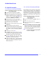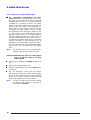
1
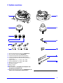
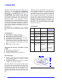
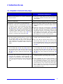
UD 124
Universal Rotary Stage
Operating manual
Knowledge of this manual is required for the operation of the instrument. Please therefore familiarize yourself with its contents and pay special regard to the sections dealing with the safe handling of the instrument.
©
Unless expressly authorized, forwarding and duplication of this document, and the utilization and
communication of its contents are not permitted. Violations will entail an obligation to pay compensation.
All rights reserved in the event of granting of patents or registration of a utility model.
Please contact:
Carl Zeiss
Mikroskopie
D-07740 Jena
Telefon: (03641) 64-1616
Fax:
(03641) 64-3144
Internet: [email protected]
http://www.zeiss.de
Subject to change
B 40-017 e / 12.96
Contents
1 Notes .................................................................................................................................2
2 System overview...............................................................................................................3
3 Application .......................................................................................................................4
4 Instructions for use............................................................................................................5
4.1 Adaptation of universal rotary stage ................................................................5
4.2 Preparation of universal rotary stage ................................................................8
4.2.1 Positioning the sample..........................................................................8
4.2.2 Imaging the sample .............................................................................8
4.2.3 Centering the universal rotary stage to the microscope axis ............8
4.2.4 Vertical adjustment of sample.............................................................8
4.2.5 Aligning the A2 and A4 axes to the eyepiece crosslines ....................8
4.3 Application examples ........................................................................................9
4.3.1 Orthoscopic work in linearly polarized light ........................................9
4.3.2 Conoscopic work in linearly polarized light ........................................9
4.3.3 Work in circularly polarized light.........................................................10
5 Modules ...................................................................................................................... ....11
5.1 Universal rotary stage .......................................................................................11
5.1.1 Sample.................................................................................................11
5.1.2 Schmidt ruler........................................................................................11
5.1.3 Segments.............................................................................................11
5.2 Objectives.........................................................................................................11
5.3 Condensers .......................................................................................................12
5.4 Wulff network ....................................................................................................12
6 Maintenance ..................................................................................................................13
7 Literature .........................................................................................................................14
8 Wulff network for stereographic projections ................................................................15
B 40-017 e / 12.96
1
1 Notes
Operation!
The instrument may be operated by
trained personnel only who must be
familiar with the possible dangers involved in microscopy and the relevant
field of application.
Dust!
Dust and dirt can impair the performance of the instrument. Therefore, protect the instrument against these interferences as far as possible. Always use
the dust cover if you do not intend to
use the microscope for longer periods
of time.
Use of toxic immersion agents!
If the toxic -bromonaphthalene is
used as an immersion agent, make sure
to avoid all skin contact with this substance to elimi-nate the possibilty of
health risks. Wear protective goggles
and gloves, if necessary..
Damage to microscope parts!
To eliminate collisions between the
objec-tives and parts of the universal
rotary stage during work, the 4-position
objective nose-piece of the Axiolab Pol
must be equipped with no more than 2
objectives, with a free nosepiece eye
between each objective. The 6position nosepiece of the Axioplan Pol
may accommodate 3 objectives
(always separated by a free eye). Use
caps to close nosepiece eyes not in
use.
2
B 40 - 017 e / 12.96
2 System overview
1
2
3
4
5
6
7
8
9
10
11
12
13
UD 124 universal rotary stage for Axiolab Pol
UD condenser 0.6 pol für Axiolab Pol
Achromat objective 5x/0.10 Pol segment
Achromat objective 20x/0.30 Pol segment
Achromat objective 50x/0.60 Pol segment for
conoscopy
Upper segments nD = 1.516; 1.556; 1.648
Lower segments nD = 1.516; 1.556; 1.648
Ball head screw driver SW 3
Pin wrench SW 1.5
Stage clamps
Schmidt ruler
UD condenser for Axioplan Pol, Axioplan 2 Pol,
Axiophot Pol, Axiophot 2 Pol
UD 124 universal rotary stage for Axioplan Pol, Axioplan 2 Pol, Axiophot Pol, Axiophot 2 Pol
B 40 - 017 e / 12.96
Fig. 1
System overview
3
3 Application
The three-axis universal rotary stage (FigFig. 1/1) is
mounted on the rotary stage of the polarization
microscope of the Axioplan Pol, Axioplan 2 Pol,
Axiophot Pol und Axiophot 2 Pol microscopes. For
the Axiolab Pol, the universal rotary stage is
equipped with a special stage carrier (Fig. 1/13)
and mounted directly on the stand in place of the
rotary stage. Observation and measurement is
generally possible in the orthoscopic and the
conoscopic mode. Linearly polarized and circularly polarized light can be used. With the help of
one rotary and two tilting axes (stage 1), the threeaxis universal rotary stage is suitable for aligning a
crystal, which normally is birefringent, in any defined direction relative to the optical axis of the
microscope.
The major fields of application of the universal
rotary stage can be classified into three categories:
Reinhard [10] and Sarantschina [12] have introduced different definitions. The axial designations
of Sarantschina are based on the inventor of the
universal rotary stage, E. S. von Fedorow. With the
three-axis universal rotary stage the A3 axis has not
been developed. This, however, is no drawback,
because three axes are absolutely adequate for
aligning any orientation in the sample relative to
the optical axis of the microscope. In addition, the
possibility of operational errors is reduced. Given
the option, old hands will therefore normally give
preference to a three-axis universal rotary stage
over the four-axis one.
Axial definition:
Berek
A1
Crystal diagnosis
Determining the optical character
Determining the absolute birefringence
Determining the grinding thickness
Measuring position and dimension of indicatrix
Measuring the optical shaft angle
Measurement of morphological reference planes,
such as cleavage faces, composition surfaces of
twins or the periphery of idiomorphous unit crystals
Determining the pleochroism
A2
A3
A4
A5
Determining the chemical composition of mixed
crystals
Examination of plagioclases
Analysis of alkali feldspas
Analysis of pyroxenes and amphiboles
Reinhard
Sarantschina
N=
Normal axis
H=
Horizont axis
A=
Auxiliary
axis
K=
Control axis
N=
Normal axis
H=
Auxiliary axis
M=
Mobile axis
I=
Immobile
axis
M=
A=
Microscope Optical miaxis
croscope
axis
=
Rotary axis of
microscope
stage
Universal
rotary stage
component
Inside rotary
axis
Inside tilt axis
Outside rotary axis
Outside tilt
axis
Rotary axis of
microscope
stage
=
Optical microscope
axis
Table 1
Structural analysis
Analysis of the structural arrangement of optically monaxial crystals, e.g. quartz in quartzite
or calcite in marble
Analysis of the structural arrangement of biaxial
crystals, e.g. muscovite in gneiss.
The most customary and also the clearest definition of the axes of a universal rotary stage is the
one introduced by Berek in 1924, in which the axis
numbers increase from the inside toward the outside. The inside rotary axis, for example, is numbered A1, the inside tilt axis A2. The rotary axes are
provided with odd, the tilt axes with even numbers.
4
Fig. 2
Axial definition of universal rotary stage
B 40 - 017 e / 12.96
4 Instructions for use
4.1 Adaptation of universal rotary stage
Axiolab Pol
Axioplan Pol, Axioplan 2 Pol,
Axiophot Pol, Axiophot 2 Pol
Remove rotary stage in accordance with micro- Center
scope manual.
the rotary stage to the microscope in
accordance with the manual, take out the reducing plate.
Remove objectives.
Remove the Pol objective and Pol condenser.
Adjust the coarse drive to its upper limit stop.
Move the stage carrier to its top stop, raise the
and lower the condenser carrier as far as
Insert the 0.6 Pol UD condenser (Fig. 1/2) in the stage
it will go.
condenser carrier of the universal rotary stage.
For this purpose, lower the condenser drive Insert the 0.6 Pol UD condenser.(Fig. 1/12) (Note!
(Fig. 3/8) as far as it will go and insert the UD
condenser (Fig. 1/2) in the dovetail guide of the
condenser carrier. Make sure the condenser is
correctly seated and clamp it (Fig. 3/16). Then
raise the condenser drive again (Fig. 3/8).
Place the condenser in an almost vertical position, slide it into the dovetail and clamp it, (see
microscope manual. If necessary, remove the
rotary stage from the stand, insert and clamp
the condenser and replace the rotary stage).
Then slighly move up the condenser drive.
Mount the universal rotary stage on the stand so Lower the stage carrier by about 15
that the retaining pin (Fig. 3/7) is in contact with
the dovetail guide of the microscope and
clamp it (Fig. 3/17). The stage is now automatically centered to the optical axis of the microscope; lower the condenser carrier as far as it
will go.
mm and
clamp it. (See microscope manual.)
Place the UD 124 universal rotary stage on the
microscope stage (Fig. 4/7) and use the ballhead screwdriver (Fig. 1/8) (or a 90° offset Allen
key) to tighten the two mounting screws (Fig. 4/4
and 10).
Set the tilt positions about the axes A2 and A4 to Set the tilt positions about the axes A2 and A4 to
0° click stops (Fig. 3/1 and. Fig. 3/19), switch to
the click stops (Fig. 3/13 and. Fig. 3/14), set the
graduated circle of the A1 axis to the 0°-mark
(Fig. 3/3) and clamp all tilt movements (Fig. 3/21
and 26).
0° click stops (Fig. 4/1 and. Fig. 4/15), switch to
the click stops (Fig. 4/13 and. Fig. 4/14 set the
graduated circle of the A1 axis to the 0°-mark
(Fig. 4/3) and clamp all tilt movements (Fig. 4/17
and 22)
Screw the UD Achromat Pol objectives (Fig. 1/3, Adjust the vertical
4, 5) into the nosepiece, always leaving one
nosepiece eye between each objective vacant. (It is recommended to use two objectives).
Use dust caps to close the vacant nosepiece
eyes.
condenser stop so that the
condenser will not hit the stage (see manual).
Check
whether the spacer ring H“0“M 27 on
W 0.8 (4549109) has been screwed into the fixed
(not centerable) nosepiece eye. (Screw in if
necessary.) Screw the UD Achromat 20x/0.30 Pol
in this nose-piece eye, screw in the other objectives so that one eye is left vacant between
each of them. Use dust caps to close the vacant nosepiece eyes.
Table 2
B 40 - 017 e / 12.96
5
4 Instructions for use
1
2
3
4
5
6
7
8
9
10
11
12
13
14
15
16
17
18
19
20
21
22
23
24
25
26
6
Vernier A2
Schmidt ruler
Vernier A1
Clamping screw A5
Click stop mechanism A5
Pins for vertical adjustment of lower
segment (4x)
Arresting pin universal rotary stage
Control for condenser height adjustment
Vertical condenser stop
Centering screw for condenser
Dovetail for condenser
Aperture diaphragm
Condenser
Click stop mechanism A2
Centering screw for condenser
Clamping screw for condenser
Clamping screw for univ. rotary
stage
Click stop mechanism A4
Vernier A4
Threaded bore for stage clamp
Clamping mechanism A2
Screw for upper segment
Lower segment
Upper segment
Annular bearing
Clamping device A4
Fig. 3
Universal rotary stage for Axiolab Pol
B 40 - 017 e / 12.96
4 Instructions for use
1
2
3
4
5
6
7
8
9
10
11
12
13
14
15
16
17
18
19
20
21
22
Vernier A2
Schmidt ruler
Vernier A1
Screw for mounting univ. rotary
stage
Click stop mechanism A5
Clamping screw for stage centering
Rotary stage of microscope
Clamping screw A5
Adjusting screw for stage centration
Mounting screw for univ. rotary
stage
Adjusting screw for stage centration
Clamping screw for stage centration
Click stop mechanism A2
Click stop mechanism A4
Vernier A4
Threaded bore for stage clamp
Clamping mechanism A2
Screw for upper segment
Lower segment
Upper segment
Annular bearing
Clamping mechanism A4
B 40 - 017 e / 12.96
Fig. 4
Universal rotary stage for Axioplan Pol
7
4 Instructions for use
4.2 Preparation of universal rotary
stage
4.2.1 Positioning the sample
Select the suitable segment pair (Fig. 1/6 and
7), The refractive indices of the sample and the
segment pair should be almost identical. For
quartz or feldspa crystals, for example, the
segment pair featuring the refractive index
nD = 1,556 should be selected, for pyroxen or
amphibol crystals the one with the refractive
index nD = 1,648.
Insert the larger, lower segment (Fig. 1/7) into
the annular bearing (Fig. 3/25) to fit the groove.
Apply immersion fluid, e.g. glycerin, to the flat
segment surface.
Position the sample and put one drop of immersion fluid on it.
Center the upper segment (Fig. 1/6) parallel to
the sample so that the screws (Fig. 3/22) touch
the threaded bores in question. Lightly tighten
the screws so that the immersion fluid is evenly
distributed and shows no bubbles.
Align the objective on the nosepiece with the
rotary axis A5 according to the microscope
manual. (For the Axioplan Pol, Axioplan 2 Pol,
Axiophot Pol and Axiophot 2 Pol microscopes,
check the center-ing of the microscope stage
and re-center it, if necessary.)
Arrest the microscope stage (Fig. 4/8). Rotate
the sample through axis A1. Use the adjusting
screws (Fig. 4/9 and 11) and pin key (Fig. 1/9) to
align the rotary axis of the universal rotary stage
relative to the rotary axis of the microscope
stage in accordance with the crosslines visible
in the eyepieces, tighten the clamping screws
(Fig. 4/6 und 12) with the ball-head screwdriver
(Fig. 1/12) (This secures the centering).
4.2.4 Vertical adjustment of sample
Loosen the clamps of axis A4 (Fig. 3/26) and
observe the sample as it is tilting. If the sample
moves in the direction of rotation, it is located
too high. If it moves opposite to the direction of
rotation, it is located too low.
If the specimen remains unchanged when it is
tilted about axis A4, it is at the correct height. In
this case the intersections of the universal rotary
stage axes, the center point of the sphere and
the focus are located in this point, which is intersected by the surface of the sample.
If the sample is too high, use the pins (Fig. 3/6)
to turn the threaded ring counter-clockwise as
seen from below. When the correct height has
been reached, lightly tighten the screws
(Fig. 3/22).
If the sample is too low, loosen screws
(Fig. 3/22) and turn the threaded ring (Fig. 3/6)
clockwise as seen from below. When the correct height has been reached, lightly tighten
the screw (Fig. 3/22), if necessary.
4.2.2 Imaging the sample
Sharply image the sample and use the condenser to illuminate it (as specified in the microscope manual). Sharply image the narrowed luminous field diaphragm together with
the sample, center and open it until the field of
view is visible.
4.2.5 Aligning the A2 and A4 axes to the eyepiece
crosslines
Tilt the universal rotary stage about the A4 and
A2 axes while observing the direction in which a
dust particle below or above the object plane
is moving.
When the stage is tilted about the A4 axis, the
particle must move parallel to the vertical line
of the eyepiece crosslines. It it fails to do so,
disengage the stage click stop mechanism
and perform the necessary alignment by rotating the stage through the A5 axis..
Activate the stage click stop mechanism.
When the stage is tilted about the A2 axis, the
particle must move parallel to the horizontal
(left-right), when tilted about the A4 axis, parallel to the vertical eyepiece crossline (topbottom). This is the standard setting.
4.2.3 Centering the universal rotary stage to the
microscope axis
The universal rotary stage of the Axiolab Pol
has already been centered by the manufacturer.
With the polarization microscopes Axioplan Pol,
Axioplan 2 Pol, Axiophot Pol and Axiophot 2 Pol
the universal rotary stage must be centered
relative to the rotary axis of the microscope
stage.
8
B 40 - 017 e / 12.96
4 Instructions for use
4.3 Application examples
4.3.2 Conoscopic work in linearly polarized light
4.3.1 Orthoscopic work in linearly polarized light
Example 1: Measuring the angle 2 V of the optical
axis of a biaxial crystal
Center the selected grain in the crosslines.
Switch in the 5x/0.13 objective (standard use).
Adjust the iris diaphragms of the 20x/0.30 and
50x/0.60 objectives and the aperture diaphragm of the condenser (Fig. 3/12) to increase the contrast of the Axiolab Pol (same
procedure for Axioplan-microscopes).
Rotate through the A1 axis to dark position.
Tilt about A4 axis (max. possible angle). Nor-
mally this will result in brightening up.
Tilt about the A2 axis to dark position.
Tilt about the A4 axis in opposite direction until it
brightens up.
Rotate through the A1 axis to extinction.
If the grain remains dark when the stage is tilted
about the A4 axis, the plane of the optical axis
lies parallel to the microscope's symmetry
plane (if not, repeat the previously described
steps).
Clamp the A2 axis (Fig. 3/21).
The advantage of the conoscopic over the orthoscopic method is that the axial directions of
monaxial or biaxial crystals can be identified directly in the interference image. For this purpose, a
high-aperture (e.g. 50x/0.60) LD (long distance)
objective and a Bertrand lens permitting observation of the rear focal plane of the objective are
required.
Example 2: Measuring the angle 2 V of the optical
axis of a biaxial crystal
(conoscopically)
Proceed as described in example 1 (steps 1 to
10).
Switch in the 50x/0.60 objective.
Switch in the Bertrand lens (focus Axioplan mi-
croscopes).
Use the graduated circle and the vernier
(Fig. 3/19) to measure the optical axis by tilting
about A4. The axial directions can be identified
from the curved, dark , hyperbola branches.
The exit point of the crystal's optical axis lies in
the vertex of the hyperbola.
Note:
If only one optical axis is located within
the tilting range about A4, proceed as
described in example 1.
For Axioplan microscopes, release the clamp-
ing device of the microscope stage (Fig. 4/5)
and rotate the universal rotary stage by 45°
through the A5 axis up to the next click stop.
Use the graduated circle and the vernier
(Fig. 3/19). to measure the optical axes (dark
position when tilted about the A4 axis).
If only one of the axes of a biaxial crystal lies
between the tilting range A4, the angle of the
optical axes must be determined using the
Wulff network (Fig. 5).
B 40 - 017 e / 12.96
9
4 Instructions for use
4.3.3 Working in circularly polarized light.
The
Axiolab Pol, Axioplan 2 Pol and Axiophot 2 Pol microscopes permit the universal rotary stage to be used also for work in circularly
polarized light. For this, the circular polarizer D
consisting of a polarizer and two /4 plates
must be used. The polarizer and one of the /4
plates is used in the place of the standard polarizer. The second /4 plate is inserted in the
compensator mount. Before doing so, adjust
the polarizer and the analyzer so that they are
at a 90° angle to each other. Align the upper
/4 plate to the lower one until dark position is
reached without adjusting the objective. Circularly polarized light can be used in conjunction with the universal rotary stage to precisely
measure the angle of the optical axes 2 V in
birefringent, optically biaxial crystals, for example. If you wish to work in linearly polarized light,
remove the two /4 plates from the beam
path.
Note:
For details on the use of circularly polarized light, please refer to Zschach [15].
Example 3: Measuring the angle 2 V of the optical
axis of a biaxial crystal in circularly
polarized light
Proceed as described in example 2 (steps 1 to
10).
Switch in the 50x/0.60 objective.
Switch in the Bertrand lens (focus Axioplan microscopes).
Use the graduated circle and the vernier
(Fig. 3/19) to measure the optical axis by tilting
about A4. The axial directions can be identified
by the two circular, dark zones with the exit
point of the optical axes in their centers .
Note:
10
If only one optical axis is located within
the tilting range about A4, proceed as
described in example 1.
B 40 - 017 e / 12.96
5 Modules
5.1 Universal rotary stage
5.2 Objectives
5.1.1 Sample
Examinations using the universal rotary stage can
only be performed with the newly computed
Achromat objectives which are screwed into the
objective nosepiece direct, without any adapter.
The engraved magnification and aperture figures
apply when used in conjunction with the segment
pair nD = 1.556.
The sample is inserted between glass segments
(Fig. 1/6 and 7) and connected with them by the
immersion fluid. The sample surface must be in the
center of the sphere. The thickness of the object
carrier should therefore be 0.9 to 1.1 mm, that of
the cover glass 0.16 to 0.18 mm, and that of the
sample 0.03 mm. If the thickness of the object
carrier and the object differs, the segments and
the sample can be vertically adjusted.
5.1.2 Schmidt ruler
The Schmidt ruler (Fig. 1/11) is used for structural
analyses. The short leg (Fig. 3/2) is inserted in one
of the trapezoidal guideways. The position of the
sample can be secured using the stage clamps
(Fig. 1/10) which must be screwed into the
threaded bores (Fig. 3/20).
5.1.3 Segments
The segments are supplied in pairs. Each pair consists of an upper segment (Fig. 1/6) with a radius of
6.24 mm and a lower segment (Fig. 1/7) with a
radius of 14.01 mm.
The stage is equipped with three segment groups
featuring different refractive indices. Segments
with the refractive index nD = 1.516 can be used,
for example, to measure the cleavage direction in
fluorite.
Segments with the refractive index nD = 1.556 are
suitable for examining quartz and feldspa crystals.
Segments with the refractive index nD = 1.648 are
intended for the measurement of higher-refracting
minerals such as pyroxenes and amphiboles, for
example. In this case, a higher-refracting contact
fluid is also recommended such as bromonaphthalene, for example.
If the objective is combined with a segment pair
featuring another refractive index, the magnification figure and the numerical aperture change by
the factor K:
x
K=
1,556
with x being the refractive index 1.516 or 1.648
(depending on the segment pair used).
In orthoscopic observation, the contrast is increased by closing the iris diaphragm with which
all objectives are equipped. The condenser stop
should be narrowed down simultaneously..
Use the Achromat 50x/0.60 objective for conoscopic observations, opening the iris diaphragm of
the objective and the aperture stop of the condenser.
Achromat objectives with segment nD = 1.556:
Magnification /
Working distance
Aperture
in mm
with
without
with
without
segment segment segsegment
ment to to samsegple surment
face
surface
5x/0.13 3.2x/0.08
2.8
9.0
5x/0.30 12.8x/0.1
4.4
10.6
9
50x/0.60 32x/0.38
2.3
8.5
Cat.No
442001
442003
442005
Table 3
B 40 - 017 e / 12.96
11
5 Modules
5.3 Condensers
For the Axioplan Pol, Axioplan 2 Pol, Axiophot Pol
and Axiophot 2 Pol microscopes, the UD 0.6 Pol
condenser , Cat.No. 445460, is used. It is suitable
for orthoscopic and conoscopic examinations.
When working orthoscopically, the condenser
aperture should be stopped down. For conoscopic work the condenser aperture must be fully
open.
With the LD 0.6 Pol condenser , Cat.No. 445311, a
condenser of identical optical performance is
available for the Axiolab Pol. The above information also applies to this condenser.
5.4 Wulff network
Evaluation of the results obtained with the universal rotary stage is made easier by using the Wulff
network (Fig. 5, page 15). It consists of the stereographic projection of meridians and latitudes onto
a horizontally oriented plane.
If the measurement of the axis angle of optically
biaxial crystals, for example, reveals one of the
axial directions to lie outside of the tilting range of
the A4 axis, the stereographic projection can be
used to determine the second axial direction and
thus the axis angle 2 V of the crystal under examination.
12
B 40 - 017 e / 12.96
6 Maintenance
For general information on care and maintenance, please refer to the operating instructions
G 42-311, B 40-016 and B 40-042.
Kindly also observe the following::
The universal rotary stage is a precision instru-
ment and must therefore be protected against
mechanical damage to ensure that settings
and adjustments are not lost.
Treat the segments with care (risk of scratching).
Glycerin
is recommended as an immersion
agent due to it being water soluble.
Always clean the universal rotary stage imme-
diately on completion of your work. For this,
loosen the knurled screws of the upper segment and lift it out of the center part of the universal rotary stage together with the sample
and the lower segment.
Carefully separate these components sideways
and rinse off the immersion fluid with clean water, or dab it off using wet cotton wool. Distilled
water is recommended for glycerin and light
gasolin for immersion oil. Use an optical cleaning cloth or leather for the actual cleaning
process.
The mechanical parts are cleaned in the same
way.
Caution! The annular groove for the lower seg-
ment and the guideway for the Schmidt rulers
must be cleaned very thoroughly due to the
high-precision fit to eliminate the possibility of
functional defects.
The
smoothness of the vertical objective adjustment must be checked at regular intervals.
On completion of your work, store the universal
rotary stage and all accessories in the storage
container supplied.
B 40 - 017 e / 12.96
13
7 Literature
[1]
Berek, M.:
Mikroskopische Mineralbestimmung mit Hilfe der Universaldrehtischmethoden.
Berlin: Bornträger 1924
[2]
Burri, C.:
Das Polarisationsmikroskop.
Basel: Birkhäuser 1950
[3]
Chudoba, K.:
Die Feldspäte und ihre praktische Bestimmung
Stuttgart: 1932
[4]
Emmons, R. C.:
The universal stage.
Mem. geol. Soc. of Amer. 8 (1943)
[5]
Hallimond, A. F.:
Universal stage methods.
The mining magazine LXXXIII (1950) pp. 12-22 and 77-80
[6]
Hofmann, J.:
Methodische Anleitung zu Bestimmung von Plagioklasen mit Hilfe
des
Universaldrehtisches.
Bergakademie Freiberg 1984
[7]
Müller, G. und Raith, M.:
Methoden der Dünnschliffmikroskopie.
Clausthal-Zellerfeld: Verl. E. Pilger (1981, 3 Aufl.)
[8]
Nickel, E.:
Aufbaukurs Petrographie,
4. Aufl., Ott-Verlag Thun (1992)
[9]
Nickel, E. und Dönhoff, J.:
Gefügekonometrie als U-Tisch-Schnell-Methode
N.Jb. Geol. Mh. 1955, S. 225-248
[10]
Reinhard, M.:
Universaldrehtischmethoden
Basel: Wepf 1931
[11]
Rinne-Berek:
Anleitung zu optischen Untersuchungen mit dem Polarisationsmikroskop (3. Aufl.)
Stuttgart: Schweizerbart 1973
[12]
Sarantschina, G. M.:
Die Fedorow-Methode
Berlin: VEB Deutscher Verlag d. Wiss. 1963
[13]
Schumann, H.:
Erweiterung der konoskopischen Beobachtungsweise durch den
Drehtisch.
Fortschr. Min. Krist. Petr. 21 (1937) 102-105
[14]
Tröger, W. E.:
Tabellen zur optischen Bestimmung der gesteinsbildenden Minerale
3. Aufl.
Stuttgart 1959
[15]
Zschach, S.
Zirkularpolarisation im Durchlicht mit den Mikroskopen Axioskop,
Axioplan und Axiophot, MICRO INFO, Edition 33, Juni 1993, Carl Zeiss
Oberkochen, Geschäftsbereich Mikroskopie
14
B 40 - 017 e / 12.96
8 Wulff network for stereografic projections
Fig. 5
Wulff network
B 40 - 017 e / 12.96
15