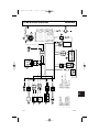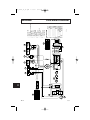
1
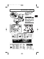
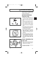
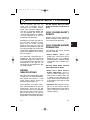
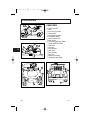
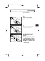
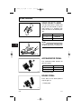
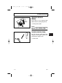
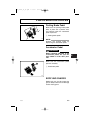
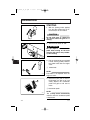
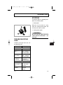
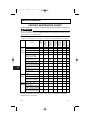
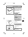
GOLF CAR
OWNER’S/
OPERATORS
MANUAL
G16A
G16E
07/12/01
1PC - G16A/E O/M
LIT196261600
*LIT196261600*
Yamaha Motor Corp., USA
Cypress, California
USA
made in
YAMAHA MOTOR
MANUFACTURING CORP.
OF AMERICA
LIT-19626-16-00
Printed in U.S.A.
KCC
JN6-F8199-13
G21A O_M IFC
8/8/00
7:56 AM
Page 1
WARNING
The engine exhaust from this product
contains chemicals known to the
State of California to cause cancer, birth
defects or other reproductive harm.
YAMAHA
LIT-CALIF-65-01
LIT_19626_16_00.qxd
7/13/01
8:42 AM
Page 1
INTRODUCTION
Congratulations on your purchase of
a Yamaha golf car. This manual contains information you will need for
proper operation, maintenance, and
care of your golf car. A thorough
understanding of these simple
instructions will help you to obtain
maximum enjoyment from your new
Yamaha.
If you have any questions about the
operation or maintenance of your golf
car, please consult a Yamaha dealer.
TECHNICAL SERVICE DEPT
GOLF CAR SALES GROUP
YAMAHA MOTOR
MANUFACTURING CORP OF
AMERICA
G16A, G16E
OWNER’S/OPERATOR’S
MANUAL
© 2000 by Yamaha Motor
Manufacturing Corporation
of America
1st edition
All rights reserved. Any reprinting
or unauthorized use without the
written permission of
Yamaha Motor Manufacturing
Corporation of America
is expressly prohibited.
Printed in U.S.A.
P/N LIT-19626-16-00
G16A/E
i
LIT_19626_16_00.qxd
7/13/01
8:42 AM
Page 2
IMPORTANT MANUAL
INFORMATION
Particularly important information is
distinguished in this manual by the
following notations:
!
The Safety Alert Symbol means
ATTENTION! BE ALERT! YOUR
SAFETY IS INVOLVED!
WARNING
Failure to follow WARNING instructions could result in severe injury
or death to the golf car
occupants, a bystander, or a
person inspecting or repairing
the golf car.
CAUTION
This message describes special
precautions that must be taken to
avoid damage to the golf car.
NOTE:
Yamaha continually seeks advancements in product design and
quality; therefore, while this manual
contains the most current product
information available at the time of
printing, there may be minor
discrepancies between your golf
car and this manual. If you
have any questions concerning this
manual, please consult your
Yamaha dealer.
●
●
This manual should be considered
a permanent part of your golf car
and should remain with the car
when resold.
WARNING
Read and understand this manual
completely before operating your
golf car.
NOTE:
This message provides additional key
information.
ii
G16A/E
LIT_19626_16_00.qxd
7/13/01
8:42 AM
Page 3
CONTENTS
WARRANTY
1
IMPORTANT LABELS
2
OPERATOR SAFETY
3
MAINTENANCE SAFETY PROGRAM
4
CONTROLS
5
PRE-OPERATION CHECKS
6
OPERATION
7
MAINTENANCE
8
1
STORAGE
9
SPECIFICATIONS
10
WIRING
11
G16A/E
iii
LIT_19626_16_00.qxd
7/13/01
8:42 AM
Page 4
WARRANTY
YAMAHA MOTOR MANUFACTURING
CORPORATION OF AMERICA
G16A, G16E
LIMITED WARRANTY
1
2
3
4
Yamaha Motor Manufacturing Corporation of America
hereby warrants that any new G16 (gas and electric
models) Yamaha Golf Car purchased from an authorized
Yamaha dealer in the United States will be free from
defects in material and workmanship for the period of
time stated herein, subject to the stated limitations.
THE PERIOD OF WARRANTY for any G16 (gas and
electric models) will be three years from date of purchase.
The first year of warranty shall cover the entire car
except for batteries, battery chargers, tires and rims,
which are warranted by their respective manufacturers.
5
The second year of warranty shall cover the engine
assembly, clutch, transmission, axles, electrical system,
frame, suspension components, electric motor, control
cables, and steering gear.
6
Parts excluded from the second year of warranty include
the body parts, seats, mats, bumper assembly, bag carrier, scorecard holder, and the trim.
7
The third year of warranty shall cover the engine assembly, clutch, transmission, axles, frame, suspension components, steering gear, and (on the G16E) electronic
speed controller.
8
Parts excluded from the third year of warranty include
the second year exclusions and the electrical system
(except electronic speed controller), electric motor, and
control cables.
9
10
11
DURING THE PERIOD OF WARRANTY any authorized
Yamaha Golf Car Dealer will, free of charge, repair or
replace, at Yamaha’s option, any part adjudged defective
by Yamaha due to faulty workmanship or material from
the factory. Parts used in warranty repairs will be warranted for the balance of the machine’s warranty period.
All parts replaced under warranty become property of
Yamaha Motor Manufacturing Corporation of America.
GENERAL EXCLUSIONS from this warranty shall
include any failures caused by:
a. Abnormal strain, neglect, or abuse, including lack of
proper maintenance, and use contrary to the
Owner’s/Operator’s Manual instructions.
b. Accident or collision damage.
c. Installation of parts or accessories that are not original equipment.
d. Fading, rust, or deterioration due to exposure or ordinary wear and tear.
e. Modification or alteration that affects the car’s condition, operation, performance, or durability, or which
makes the car serve a purpose other than use as a
two-person, golf course vehicle.
f. Damage due to improper transportation.
g. Acts of God (i.e. lightning, hail damage, flooding,
fire, etc.)
1-1
SPECIFIC EXCLUSIONS from this warranty shall
include any parts replaced due to normal wear or routine
maintenance; including oil, air filter elements, brake
shoes, spark plugs, starter and clutch drive belts. Any
charges incurred in transporting a golf car to and from
an authorized Yamaha Golf Car Dealer for service or in
performing field service is also excluded from this warranty.
THE CUSTOMER’S RESPONSIBILITY under this warranty shall be to:
1. Operate and maintain the golf car as specified in the
appropriate Owner’s/Operator’s Manual;
2. Give notice to an authorized Yamaha dealer of any
and all apparent defects within ten (10) days after
discovery, and make the machine available at that
time for inspection and repairs by the dealer’s authorized representative.
WARRANTY TRANSFER: To transfer any remaining
warranty from the original purchaser to any subsequent
purchaser, it is imperative that the machine be inspected and registered for warranty by an authorized Yamaha
Golf Car Dealer. In order for this warranty to remain in
effect, this inspection and registration must take place
within ten (10) days after transfer. An inspection and registration fee may be charged for this service.
YAMAHA MOTOR MANUFACTURING CORPORATION OF AMERICA MAKES NO OTHER WARRANTY
OF ANY KIND, EXPRESSED OR IMPLIED. ALL
IMPLIED WARRANTIES OF MERCHANTABILITY AND
FITNESS FOR A PARTICULAR PURPOSE WHICH
EXCEED THE OBLIGATIONS AND TIME LIMITS
STATED IN THIS WARRANTY ARE HEREBY DISCLAIMED BY YAMAHA MOTOR MANUFACTURING
CORPORATION OF AMERICA AND EXCLUDED
FROM THIS WARRANTY.
SOME STATES DO NOT ALLOW LIMITATIONS ON
HOW LONG AN IMPLIED WARRANTY LASTS, SO
THE ABOVE LIMITATION MAY NOT APPLY TO YOU.
ALSO EXCLUDED FROM THIS WARRANTY ARE
ANY INCIDENTAL OR CONSEQUENTIAL DAMAGES
INCLUDING LOSS OF USE. SOME STATES DO NOT
ALLOW THE EXCLUSION OR LIMITATION OF INCIDENTAL OR CONSEQUENTIAL DAMAGES, SO THE
ABOVE EXCLUSION MAY NOT APPLY TO YOU.
THIS WARRANTY GIVES YOU SPECIFIC LEGAL
RIGHTS, AND YOU MAY ALSO HAVE OTHER
RIGHTS WHICH VARY FROM STATE TO STATE.
YAMAHA MOTOR MANUFACTURING
CORPORATION OF AMERICA
Newnan, Georgia 30265-1320
Effective Date: 2/1/96
LIT-13710-00-96
G16A/E
LIT_19626_16_00.qxd
7/13/01
8:42 AM
Page 5
WARRANTY
YAMAHA MOTOR MANUFACTURING
CORPORATION OF AMERICA
SPECIALTY VEHICLE ENGINES
EMISSION CONTROL WARRANTY
1
2
YOUR WARRANTY RIGHTS AND OBLIGATIONS
In complance with the California Air Resources
Board, Yamaha Motor Manufacturing Corporation of
America is pleased to explain the emission control
system warranty on your 1996 or later specialty
vehicle engine. New Yamaha speciality vehicle
engines must be designed, built and equipped to
meet stringent anti-smog standards. Yamaha must
warrant the emission control system on your speciality vehicle engine for the periods of time listed
below provided there has been no abuse, neglect or
improper maintenance of your speciality vehicle
engine.
Your emission control system may include parts
such as the carburetor or fuel-injection system, the
ignition system, and catalytic converter. Also included may be hoses, belts, connectors and other emission-related assemblies.
●
If you have any questions regarding your warranty
rights and responsibilities, you should contact the
Yamaha Customer Relations Department at
(770) 254-4164.
Yamaha Motor Manufacturing Corporation of
America warrants to the ultimate purchaser and
each subsequent purchaser thereafter that each
new 1996 and later model year specialty vehicle
engine certified for sale is:
1.
Where a warrantable condition exists, Yamaha will
repair your specialty vehicle engine at no cost to you
including diagnosis, parts and labor.
2.
MANUFACTURER’S WARRANTY COVERAGE
The 1996 and later specialty vehicle engines are
warranted for two years. If any emissions-related
part on your engine is defective, the part will be
repaired or replaced by Yamaha.
OWNER’S WARRANTY RESPONSIBILITIES
● As the specialty vehicle engine owner, you are
responsible for the performance of the required
maintenance listed in your owner’s manual.
Yamaha recommends that you retain all receipts
covering maintenance on your specialty vehicle
engine, but Yamaha cannot deny warranty solely
for the lack of receipts or for your failure to ensure
the performance of all scheduled maintenance.
●
G16A/E
As the specialty vehicle engine owner, you
should also be aware that Yamaha may deny you
warranty coverage if your specialty vehicle
engine or a part has failed due to abuse, neglect,
improper maintenance or unapproved modifications.
You are responsible for presenting your specialty
vehicle engine to a Yamaha dealer as soon as a
problem exists. The warranty repairs should be
completed in a reasonable time, not to exceed 30
days.
Designed, built, and equipped so as to conform,
at the time of sale, with all applicable regulations adopted by the California Air Resources
Board, and
All warranted parts are free from defects in
material and workmanship for the warranty
period of the specialty vehicle engine or the
period prior to the first scheduled replacement
point of the warranted part as required by the
maintenance schedule, if applicable, whichever
is less. A defect exists when a deficiency in
material or workmanship is such that an emission-related warranted part does not function
as designed.
The warranty period begins on the date that the
specialty vehicle engine is delivered to an ultimate
purchaser or on the date it is first placed in service.
WARRANTED PARTS INCLUDE the following:
1. Fuel Metering System
Carburetor and internal parts (or fuel injection)
Air/fuel ratio feedback and control system
Cold start enrichment system
2.
Air Induction System
Controlled hot air intake system
Intake manifold
1-2
3
4
5
6
7
8
9
10
11
LIT_19626_16_00.qxd
7/13/01
8:42 AM
Page 6
WARRANTY
3.
Ignition System
Spark plugs *
Magneto or electronic ignition system
Spark advance/retard system
4.
Exhaust Gas Recirculation (EGR) System
EGR valve body, and carburetor spacer if
applicable
EGR rate feedback and control system
5.
Air Injection System
Air pump or pulse valve
Valves affecting distribution of flow
Distribution manifold
6.
Catalyst or Thermal Reactor System
Catalytic converter
Thermal reactor
Exhaust manifold
7.
Particulate Controls
Traps, filters, precipitators, and any other
device used to capture particulate emissions
8.
Miscellaneous Items Used in Above Systems
Vacuum, temperature, and time sensitive
valves and switches
Electronic controls
Hoses, belts, connectors, and assemblies
1
2
3
4
5
6
9.
7
Engine components damaged due to a failure
under warranty of a warranted part.
* The original spark plug(s) are warranted for the
period of replacement indicated in the
Owner’s/Operator’s Manual and not the useful life of
the specialty vehicle engine (see your Owner’s
Manual).
8
DURING THE PERIOD OF THIS WARRANTY
9
Yamaha Motor Manufacturing Corporation of
America will repair or replace any warranted part
deemed defective by Yamaha during the scope of
the warranty without charge to the owner, including
parts, labor, and diagnosis. This work must be done
at an authorized Yamaha dealer. Give notice to an
authorized Yamaha dealer of any apparent defect(s)
within a reasonable period of time after discovery.
The specialty vehicle engine must be made available for inspection by an authorized Yamaha dealer.
10
11
1-3
OWNER’S RESPONSIBILITY: The owner of the
specialty vehicle engine is responsible for the performance of required maintenance (see your
Owner’s/Operator’s Manual). Receipts and maintenance records covering the performance of regular
maintenance should be retained in the event questions arise concerning maintenance. The receipts
should be transferred to each subsequent owner of
this specialty vehicle engine.
The emission control systems of your Yamaha specialty vehicle engine were designed, built, tested,
and certified as being in conformity with California
emission control regulations using genuine Yamaha
parts. Accordingly, it is recommended that any
replacement part(s) used for maintenance, replacement, or repair of emission control systems be
Yamaha parts. The owner may elect to have maintenance, replacement, or repair of the emission
control devices and systems performed by any
repair establishment or individual, and may elect to
use parts other than Yamaha parts for such maintenance, replacement, or repair without invalidating
this warranty. However, the cost of such service or
parts will not be covered under the warranty.
EXCLUSIONS: No warranty coverage will be
allowed if the part(s) failure was caused by
owner/operator abuse, neglect, tampering, improper
adjustment unless performed by a dealer during
warranty repair work, modification, misuse, alteration, or improper maintenance (see your Owner’s/
Operator’s Manual).
Use of parts which are not qualitatively equivalent to
genuine Yamaha parts, improper service, or lack of
required maintenance which causes failure of a
warranted part may constitute abuse and/or improper service, thereby invalidating warranty liability
hereunder.
This warranty does not cover damage resulting from
accidents, acts of nature, or other events or occurrences beyond the control of Yamaha. Yamaha
Motor Manufacturing Corporation of America
expressly disclaims responsibility for any and all
consequential damages, such as loss of time,
inconvenience, loss of use of the specialty vehicle,
or commercial loss.
Yamaha Motor Manufacturing Corporation of
America
1000 Hwy. 34 East
Newnan, GA 30265
G16A/E
LIT_19626_16_00.qxd
7/13/01
8:42 AM
Page 7
IMPORTANT LABELS
1
6 G16E
5 G16A
4 G16E
3 G16A
SAFETY AND
INSTRUCTION
LABELS
2
1
2
WARNING
Y-505
1
Please read the following
labels carefully before
operating your golf car,
and promptly replace any
labels which become damaged or removed.
6
3
4
5
6
7
4
Y-500
8
9
2
10
11
3
G16A/E
5
Y-502
2-1
LIT_19626_16_00.qxd
7/13/01
8:42 AM
Page 8
IMPORTANT LABELS
GOLF CAR SERIAL
NUMBER
1
The golf car serial number is stamped
in the location shown.
2
3
Y-102a
4
NOTE:
The first three digits of the serial number are for model identification; the
remaining digits are the unit production number. Keep a record of these
numbers for reference when ordering
parts from a Yamaha dealer.
5
ç Engine Information
C
6
7
Y-852A
8
THIS ENGINE MEETS 2000-2001 CALIFORNIA EMMISSION REGULATIONS FOR OFF-ROAD ENGINES.
THIS ENGINE CONFORMSTO **(*****.******) U.S. EPA REGULATIONS FOR SMALL NONROAD ENGINES.
JR3-2179R-04
Y-851
9
10
11
2-2
G16A/E
LIT_19626_16_00.qxd
7/13/01
8:42 AM
Page 9
! OPERATOR SAFETY
Yamaha golf cars are designed to be
simple to operate. However, be sure
to observe the following:
BEFORE OPERATING
THE GOLF CAR
2
●
Read this Owner’s/Operator’s manual and all safety and instruction
labels on the golf car before operating.
●
Perform the pre-operation checks
found in Section 6 of this manual.
●
Only authorized people should
drive the golf car, from the driver’s
side only, and only in designated
areas.
Y-8
1
3
4
5
●
Do not allow more than two people
to ride in the golf car. This golf car is
restricted to two occupants.
6
●
Do not operate the golf car while
under the influence of alcohol or
drugs; their affect on vision and
judgment make operating a golf car
dangerous.
7
●
Do not operate the golf car on public streets, roads or highways. Such
use is prohibited by law, and dangerous. Operation on public roads
can result in collision with other
vehicles.
Y-68
8
9
10
WHILE OPERATING THE
GOLF CAR
●
Keep your entire body inside the
golf car, remain seated, and hold on
when the car is in motion.
●
Do not start the golf car until all
occupants are seated.
Y-67
G16A/E
3-1
11
LIT_19626_16_00.qxd
7/13/01
8:42 AM
Page 10
! OPERATOR SAFETY
1
2
3
●
Keep your hands on the steering
wheel and your eyes on the path
ahead.
●
Use extra care in congested areas
or when backing up. Always back
up slowly, and watch carefully.
●
Avoid starting or stopping abruptly.
●
Vary the speed of the golf car to
match the terrain of the course.
●
Avoid turning the steering wheel too
sharply at higher speeds.
●
Always drive slowly straight up or
straight down slopes – never at an
angle.
●
Do not run the engine indoors
(G16A). Exhaust gas is poisonous.
●
Do not make any modification or
addition which affects capacity or
safe operation, or make any
changes not in accordance with the
owner’s/operator’s manual.
4
5
6
Y-10
7
8
9
Y-9
10
11
Y-69
3-2
G16A/E
LIT_19626_16_00.qxd
7/13/01
8:42 AM
Page 11
! MAINTENANCE SAFETY PROGRAM
Like all machines, golf cars can
cause injury if improperly used or
maintained. This section contains
broad safety practices required for
safe golf car operation. Before golf
cars are operated, golf course personnel should establish any additional safety practices that may be
required for safe operation.
Experience has shown that golf cars
are safe when operated in accordance with the safety warnings
affixed to every golf car. This safe
operation is enhanced when golf cars
are used according to the safety rules
and practices established to meet the
terrain and conditions of the course
they are used on.
Do Not Operate Golf Cars When
Under The Influence Of Alcohol Or
Drugs
GOLF COURSE SAFETY
SURVEY
2
Perform safety surveys regularly to
identify hazardous areas where golf
cars should not be operated.
3
GOLF COURSE HAZARD
PREVENTION
DRIVER
QUALIFICATIONS
5
Steep Grades. Where steep
grades exist, restrict golf cars to
designated golf car pathways
where possible. In addition, identify
steep grades with a suitable warning like:
6
Warning: Steep Grade, Descend
Slowly With Foot On Brake
●
Allow only authorized people to operate golf cars. It is recommended that
only people who possess a valid
motor vehicle driver’s license be
allowed to operate golf cars.
Place operation and safety instructions recommended by the golf car
manufacturer, along with the golf
course safety rules, in a conspicuous
place near the golf car rental area or
golf car pick-up area. It is also recommended that the following warning
be posted in a conspicuous location:
G16A/E
4
The following golf course hazards
must be made safe:
●
The information contained here is
intended for golf course personnel
responsible for golf car safety. If you
are responsible for the operation and
maintenance of this golf car, we
encourage you to implement this golf
car safety program.
1
●
Sharp Turns, Blind Corners,
Bridge Approaches. Chain or
rope off these potentially hazardous areas or identify them with
a suitable warning describing the
nature of the hazard and the proper precautions to be taken to avoid
the hazard.
Wet Areas. Wet grass may cause a
golf car to lose traction and may
affect stability. Chain or rope off wet
areas or identify wet areas with a
suitable warning.
4-1
7
8
9
10
11
LIT_19626_16_00.qxd
7/13/01
8:42 AM
Page 12
! MAINTENANCE SAFETY PROGRAM
1
●
Loose Terrain. Loose terrain may
cause a golf car to lose traction and
may affect stability. Repair loose terrain, chain or rope off these areas,
or identify loose terrain with a suitable warning.
●
Golf Car and Pedestrian Interference. Reroute golf car traffic or
pedestrian traffic in congested
areas wherever possible to prevent
accidents. If it is impractical to
reroute traffic, erect warning signs
to warn pedestrians of golf car traffic, and to warn golf car operators to
drive slowly, use caution, and watch
for pedestrians.
2
3
4
5
6
MAINTENANCE
REQUIRED FOR GOLF
CAR SAFETY
7
Practice the following to help ensure
the safety of golf car operators:
8
●
Preventative Maintenance. Perform all scheduled maintenance in
accordance with manufacturer’s
recommendations to provide the
golfing patron with a safe, properly
operating golf car.
●
Personnel. Allow only qualified,
trained, and authorized personnel
to inspect, adjust, and maintain golf
cars.
●
Parts and Materials. Use only
replacement parts and materials
recommended by the manufacturer.
9
10
11
4-2
●
Ventilation. Properly ventilate all
maintenance and storage areas in
accordance with applicable fire
codes and ordinances to avoid fire
hazards. Ventilation is required to
remove flammable vapors and
fumes from gasoline powered car
storage areas. Ventilation is also
required to remove hydrogen gas
from electric powered car storage
areas during the charging process.
For electric powered golf cars, the
amount of hydrogen gas emitted during charging depends on a number of
factors, such as the condition of the
batteries, the output rate of the battery charger, and the amount of time
the batteries are on charge. Because
of the highly volatile nature of hydrogen gas and its propensity to rise and
accumulate at the ceiling in pockets, a
minimum of 5 air changes per hour is
recommended. Consult applicable fire
and safety codes for the specific ventilation levels requirement, as well as
requirements for the use of explosion
proof electrical apparatus.
G16A/E
LIT_19626_16_00.qxd
7/13/01
8:42 AM
Page 13
! MAINTENANCE SAFETY PROGRAM
SAFETY PRECAUTIONS
DURING MAINTENANCE
When performing maintenance, follow all safety instructions contained
in the manufacturer’s operation and
service manuals, as well as the following safety procedures:
●
Record all maintenance performed
in a maintenance record log by
date, name of person performing
maintenance, and type of maintenance. Periodically inspect maintenance log to ensure accurate and
complete entries.
●
Provide operator comment cards to
assist in identifying non-periodic
maintenance needs for specific golf
cars.
●
Properly immobilize golf car before
beginning any maintenance.
●
Properly block chassis before
working underneath golf car.
●
●
Before disconnecting any part of
the fuel system, drain the applicable part of the system to prevent
fuel leaks.
Maintain in a legible condition all
nameplates, warnings, and instructions provided by the manufacturer.
●
If new nameplates, warnings, or
instructions are needed, contact
your Yamaha dealer.
●
●
●
●
●
Avoid fire hazards, and have appropriate fire protection equipment
available.
Before working on an electric golf
car, disable the car’s electrical system in accordance with the manufacturer’s instructions.
Use only properly insulated tools
when working on electrically powered golf cars or around batteries.
Maintain all safety devices including brakes, steering mechanisms,
warning devices, and governors, in
a safe operating condition. Do not
modify these safety devices as
supplied by the manufacturer.
After each maintenance or repair,
the car must be driven by a qualified, trained, and authorized person – in an area free of pedestrian
traffic – to ensure proper operation
and adjustment.
G16A/E
1
2
3
4
5
6
FUEL HANDLING/
STORAGE AND
BATTERY CHARGING
7
Take the following precautions to
ensure maintenance worker safety:
8
Supervise the storage and handling of liquid fuels in accordance
with applicable fire and safety
requirements.
9
●
●
Only use battery changing and
charging facilities and procedures
that are in accordance with applicable ordinances and regulations.
●
Periodically inspect fueling and
charging facilities and procedures
to be certain that applicable safety
codes, regulations, and procedures
are being followed.
4-3
10
11
LIT_19626_16_00.qxd
7/13/01
8:42 AM
Page 14
CONTROLS
1
FEATURES
10 7
2
18
3
4
Y-506
1
9
8
6
5
5
4
6
Y-12
1
2
3
4
5
6
7
8
9
a
b
c
d
e
f
g
h
i
Steering wheel
Seat
Fuel cap (for G16A)
Brake pedal
Parking brake pedal
Accelerator pedal
Drive selector lever
Main switch
Oil warning light (for G16A)
Choke knob (for G16A)
Front cowl
Front tire
Front bumper
Rear cowl
Rear bumper
Rear tire
Battery (for G16A)
Receptacle (for G16E)
7
2
8
11
3
14
9
12
17
10
15
11
16
Y-507
13
Y-13
5-1
G16A/E
LIT_19626_16_00.qxd
7/13/01
8:42 AM
Page 15
CONTROLS
MAIN SWITCH
1
The main switch controls the following items:
OFF
Ignition circuit is switched off.
The key can be removed only in this
position.
OF
F
2
3
ON
4
Y-15
5
ON
Electrical circuits are switched on.
The golf car can be driven.
OF
F
6
ON
7
Y-16
W AO I L
RN
ING
ON
A
OF
F
Y-17
OIL WARNING LIGHT
(G16A)
8
When the engine oil level falls below
an acceptable level, this light comes
on. If the light comes on, stop the
engine, check the engine oil level,
and add oil as necessary. (See
page 6-3).
9
å Oil warning light
G16A/E
10
11
5-2
LIT_19626_16_00.qxd
7/13/01
8:42 AM
Page 16
CONTROLS
DRIVE SELECT LEVER
1
The drive select lever is used to shift
the golf car into forward or reverse.
After coming to a complete stop,
move the lever to the desired position.
2
3
Y-18
Lever Position
Car Movement
F
FORWARD
R
REVERSE
4
NOTE:
The back-up buzzer will beep when
the drive select lever is turned to “R.”
5
6
Y-19
7
ACCELERATOR PEDAL
A
8
The accelerator pedal controls the
golf car’s speed.
9
Action
Car Speed
Depress pedal
Increase
Release pedal
Decrease
Y-20
10
å Accelerator pedal
BRAKE PEDAL
11
Press down on the brake pedal to
stop the golf car.
å Brake pedal
A
Y-21
5-3
G16A/E
LIT_19626_16_00.qxd
7/13/01
8:42 AM
Page 17
CONTROLS
PARKING BRAKE
PEDAL
1
A
Press down on the parking brake
pedal whenever parking the golf car.
2
å Parking brake pedal
Y-22
NOTE:
Release the parking brake by
depressing the accelerator pedal.
3
4
CHOKE KNOB (G16A)
A
Pull and hold out choke knob when
starting a cold engine. Release the
knob after the engine starts.
5
å Choke knob
6
E
OK
CH
Y-23
7
8
9
10
11
G16A/E
5-4
LIT_19626_16_00.qxd
7/13/01
8:42 AM
Page 18
PRE-OPERATION CHECKS
Pre-operation checks should be
made each time you use your golf
car. Get in the habit of performing the
following checks in the same way so
that they become second nature.
1
2
WARNING
3
●
4
●
5
Be sure the main switch key is
removed before performing the
pre-operation checks to prevent
accidental starting, and apply
the parking brake to keep the car
from moving.
For the G16A: During the preoperation checks, avoid touching engine parts or the muffler
while they are still hot.
6
PRE-OPERATION
CHECKLIST
7
Before each use check the following:
✔ Fuel system (G16A)
✔ Engine oil level (G16A)
✔ Battery
✔ Tire condition
✔ Steering system
✔ Back-up buzzer
✔ Pedal operation
✔ Body and chassis
8
9
10
SEAT
11
Open the seat for checking and servicing.
Y-512
6-1
G16A/E
LIT_19626_16_00.qxd
7/13/01
8:42 AM
Page 19
PRE-OPERATION CHECKS
FUEL SYSTEM (G16A)
1
Make sure there is sufficient fuel in
the tank, and check fuel line and connections for leakage.
B
2
å Fuel tank
∫ Fuel cap
A
3
Y-513
WARNING
Gasoline and its vapors are highly
flammable and explosive.
● Do not smoke when refueling
and keep away from sparks,
flames, or other sources of ignition.
● Stop engine and allow it to cool
for several minutes before refueling.
● Refuel in a well-ventilated area.
● Take care not to spill gasoline. If
gasoline spills, wipe it up immediately with dry rags. Always dispose of gasoline-soaked rags
properly.
● Tighten the filler cap securely
after refueling.
● If you swallow gasoline, inhale a
lot of gasoline vapor, or get gasoline in your eyes, get immediate
medical attention.
● If any gasoline gets on your skin,
immediately wash with soap and
water. Change clothing if gasoline spills on it.
Recommended fuel:
Unleaded gasoline
Fuel tank capacity:
6.3 US gal
(24.0 L, 5.3 Imp gal)
G16A/E
4
5
6
7
8
9
10
11
CAUTION
Avoid using gasoline blended with
methyl alcohol which can damage
fuel system parts.
6-2
LIT_19626_16_00.qxd
7/13/01
8:42 AM
Page 20
PRE-OPERATION CHECKS
ENGINE OIL (G16A)
1
With the golf car parked on level
ground, remove the dipstick and
make sure the engine oil is between
the MIN and MAX marks (the crosshatched area on the end of the dipstick).
2
3
Y-514
å Oil level dipstick
∫ Maximum oil level
ç Safe operating range
B
4
MIN
If the oil level is below the MIN mark
on the dipstick, add oil through the oil
filler hole until the oil level is between
the MIN and MAX marks.
MAX
5
C
A
6
Y-28
å Oil filler hole
A
CAUTION
7
●
8
●
Y-515
Use care not to fill past the MAX
dipstick mark, and be sure no
foreign material enters the
crankcase.
Use care not to get oil on the
starter belt.
9
10
Recommended oil:
YAMALUBE 4-cycle oil or
SAE 10W-30
11
Engine oil capacity:
1.16 US qt
(1.0 L, 0.24 Imp gal)
Oil change quantity:
1.0 US qt
(0.9 L, 0.19 Imp gal)
6-3
NOTE:
The distance between the dipstick
marks represents approx. 1/2 US qt
(1/2 L) of oil.
NOTE:
Recommended engine oil classification: API Service SE, SF, or SG.
Engine oils labeled “Energy Conserving II” are recommended.
G16A/E
LIT_19626_16_00.qxd
7/13/01
8:42 AM
Page 21
PRE-OPERATION CHECKS
Engine Cooling Inlet Duct
1
Check the engine cooling inlet duct for
debris. Remove any debris present.
A
2
å Engine cooling inlet duct
BATTERY
Charge G16E batteries before each
use. See charging steps in chapter 8,
Maintenance.
G16A1
Check that the battery (G16A) or batteries (G16E) are held securely in
place to prevent the batteries from
being damaged from vibration or jarring. Also check that no battery caps
are missing to prevent battery acid
from spilling from the battery. Check
the battery terminals for corrosion.
TIRE CONDITION
3
4
5
6
7
Tire Air Pressure
Check the tire air pressure before
operating the golf car.
Tire pressure:
8
9
For G16A: 16 psi
(108 kPa, 1.1 kgf/cm2)
Y-30
A
10
For G16E: 20 psi
(137 kPa, 1.4 kgf/cm2)
11
Tire Wear Limit
Check the tire surface for damage,
cracks or embedded objects. When
tire tread wears down to 0.04 in. (1
mm), replace the tire.
Y-31
G16A/E
å Wear limit
6-4
LIT_19626_16_00.qxd
7/13/01
8:42 AM
Page 22
PRE-OPERATION CHECKS
STEERING SYSTEM
1
Check the steering system for excessive freeplay by:
2
3
4
Y-32
5
●
moving the steering wheel up and
down, and back and forth.
●
turning the steering wheel slightly
to the right and left.
If you feel excessive freeplay, or hear
rattling sounds which may indicate
loose steering components, consult a
Yamaha dealer.
BACK-UP BUZZER
Check the back up buzzer by moving
the drive select lever to “R” for
reverse. The buzzer should sound.
6
7
Y-33
8
PEDAL OPERATION
Check the following pedal controls for
proper operation. If a pedal does not
work properly, consult a Yamaha
dealer.
9
10
Brake Pedal
11
Make sure the brake pedal feels firm
when pressed and returns to its original position when released.
å Brake pedal
A
Y-21
6-5
G16A/E
LIT_19626_16_00.qxd
7/13/01
8:42 AM
Page 23
PRE-OPERATION CHECKS
Parking Brake Pedal
1
Make sure the parking brake pedal
locks in place with a positive click,
and releases when the accelerator
pedal is pressed.
A
2
å Parking brake pedal
Y-22
NOTE:
Release the parking brake by
depressing the accelerator pedal.
3
4
Accelerator Pedal
5
WARNING
Before checking operation of the
accelerator pedal, be sure the
main switch is in the “OFF” position.
Make sure the accelerator pedal
operates smoothly.
A
å Accelerator pedal
6
7
8
9
Y-20
BODY AND CHASSIS
10
Before each use, visually inspect the
golf car body and chassis for damage
and/or missing parts.
G16A/E
6-6
11
LIT_19626_16_00.qxd
7/13/01
8:42 AM
Page 24
OPERATION
STARTING
1
1. With the parking brake applied,
turn the drive select lever to “F”
for forward, or “R” for reverse.
2
CAUTION
3
Y-18
Do not shift from “F” forward to
“R” reverse while the golf car is
moving.
2. Turn the main switch to “ON.”
4
WARNING
OF
F
Do not depress the accelerator
pedal when turning on the main
switch or the golf car may suddenly start moving.
5
ON
6
Y-16
3. Pull the choke knob out and hold
it while starting (G16A). Release
the choke knob after the engine
starts.
7
8
å Choke knob
A
E
OK
CH
9
Y-23
10
NOTE:
The choke is not required when the
engine is warm.
4. Check that your path is clear in
the direction you plan to go, and
slowly depress the accelerator
pedal. The golf car will start to
move.
A
11
å Accelerator pedal
Y-20
7-1
NOTE:
The parking brake automatically
releases when the accelerator pedal
is depressed.
G16A/E
LIT_19626_16_00.qxd
7/13/01
8:42 AM
Page 25
OPERATION
STOPPING
1
To stop the golf car, gradually press
down on the brake pedal.
B
å Brake pedal
2
When the car has come to a stop,
apply the parking brake pedal and
turn the main switch to “OFF.”
3
∫ Parking brake pedal
4
CAUTION
A
Y-65
Do not hold the golf car on an
incline with the accelerator – use
the brake.
5
TROUBLESHOOTING
G16A
6
If G16A’s gas engine won’t start, use
the following chart:
7
Cause
Remedy
Fuel System
No fuel in tank Fill fuel tank
Clogged fuel
Clean fuel
line
line – Consult
Yamaha dealer
Foreign matter Clean fuel
in fuel filter
fiter – Consult
Yamaha dealer
Clogged
Clean carburetor
carburetor
– Consult
Yamaha dealer
Electrical System
Spark plug dirty Clean carbon
with carbon, or or wipe spark
wet
plug dry
Faulty ignition
Consult
system
Yamaha
dealer
G16A/E
8
9
10
11
7-2
LIT_19626_16_00.qxd
7/13/01
8:42 AM
Page 26
MAINTENANCE
1
PERIODIC MAINTENANCE CHARTS
Regular maintenance is required for the best performance and safe operation of your golf car.
WARNING
2
3
Be sure to turn off the main switch and apply the parking brake when you perform maintenance unless
otherwise specified. If the owner is not familiar with machine servicing, this work should be done by a
Yamaha dealer or other qualified mechanic.
FOR G16A
C - CHECK
CA - CHECK AND ADJUST
R - REPLACE
Remarks
4
5
CL - CLEAN AND LUBRICATE
125 rds
125 hrs
600 mls
1000 kms
(Every 6
months)
L - LUBRICATE
250 rds
250 hrs
1200 mls
2000 kms
(Every
year)
500 rds
500 hrs
2500 mls
4000 kms
(Every
2 years)
1000 rds
1000 hrs
5000mls
8000 kms
(Every
4 years)
Page
PRE-
Check engine oil
C
C
C
OPER-
Check air cooling duct
C
C
C
C
C
C
*
ATION
Check fuel lines for leakage
C
C
C
C
C
C
6-2
CHECKS Check fuel level
6
7
8
9
6-3
C
C
C
C
C
C
6-2
Check for looseness
and corrosion of battery
terminals and hold downs
C
C
C
C
C
C
6-4
Check brake pedal freeplay
and adjust if necessary
C
CA
CA
CA
CA
CA
8-18
Check steering operation
C
C
C
C
C
Check tire pressure, tread
depth, tire surface for damage
C
CA
CA
CA
CA
CA
Check body and chassis for
damage
C
C
C
C
C
C
Check tightness of all bolts,
nuts, and screws
C
C
C
C
C
C
*
Check reverse buzzer
operation
C
C
C
C
C
C
6-5
6-5
6-4
6-6
EVERY
Check fuel filter for clogging
C
C
C
C
C
*
MONTH
Check wear of drive belt
C
C
C
C
C
8-9
Check operation of
Forward / Reverse shifting
C
C
C
C
C
—
Clean / Lube pedal control area
CL
10
11
PreOperation
S - SERVICE
20 Rounds
20 hours
100 miles
160 kms
(Every
month)
EVERY 6 Wash pre-filter, check air
MONTHS cleaner element
—
S
S
S
S
8-7
Check spark plug and plug cap
condition** / Check compression
C
C
C
C
8-5/*
Check shock absorbers for oil
leaks and damaged springs
C
C
C
*
* Items with out a page number reference should be serviced by a Yamaha dealer or other qualified
mechanic. This manual does not contain these procedures. They are contained in the Service Manual.
**Related to emission control system.
8-1
G16A/E
LIT_19626_16_00.qxd
7/13/01
8:42 AM
Page 27
MAINTENANCE
FOR G16A (continued)
C - CHECK
CA - CHECK AND ADJUST
R - REPLACE
S - SERVICE
CL - CLEAN AND LUBRICATE
500 rds
500 hrs
2500 mls
4000 kms
(Every
2 years)
1000 rds
1000 hrs
5000mls
8000 kms
(Every
4 years)
Page
R
R
R
8-6
CA
CA
CA
*
Check starter V-belt for
damage and tension
C
C
C
*
Check drive belt for slippage,
wear or scratches
C
C
C
8-8
Check sliding sheave and
ramp shoes; Grease secondary
sheave bearing.
CL
CL
CL
*
Grease primary sheave
L
L
L
*
Check operation of speed limiter
C
C
C
*
Apply battery terminal protectant
S
S
S
—
Check wiring connections
and insulation
C
C
C
—
Check shoe lining thickness
and rear axle bearing play
C
C
C
*
Check kingpin play, seal, and
cap / Adjust wheel alignment
CA
CA
CA
*
Check wheel nut tightness,
front wheel bearing play
C
C
C
*
Check gear box oil level
and leakage
C
C
C
8-16
CA
CA
CA
*
C
S
*
R
*
CA
*
R
*
CA
*
EVERY
Replace engine oil
YEAR
Adjust throttle cables,**
choke cable, check carburetor
throttle shaft for wear**
Check operation and adjust
pedal stop if necessary
EVERY Check brushes for wear and
2 YEARS commutator for dirt
EVERY Replace fuel filter and
4 YEARS fuel hoses
Check tightness of cylinder
head / Adjust valves
Replace gear box oil
Check for grease leakage;
adjust gearbox if necessary
125 rds
125 hrs
600 mls
1000 kms
(Every 6
months)
L - LUBRICATE
250 rds
250 hrs
1200 mls
2000 kms
(Every
year)
Remarks
20 Rounds
Pre20 hours
Opera- 100 miles
tion
160 kms
(Every
month)
2
3
4
5
* Items with out a page number reference should be serviced by a Yamaha dealer or other qualified
mechanic. This manual does not contain these procedures. They are contained in the Service Manual.
**Related to emission control system.
G16A/E
1
8-2
6
7
8
9
10
11
LIT_19626_16_00.qxd
7/13/01
8:42 AM
Page 28
MAINTENANCE
1
FOR 16E
C - CHECK CA - CHECK AND ADJUST R - REPLACE
Remarks
3
4
5
6
EVERY
MONTH
8
250 rds
250 hrs
1200 mls
2000 kms
(Every
Year)
500 rds
500 hrs
2500 mls
4000 kms
(Every 2
years)
1000 rds
1000 hrs
5000 mls
8000 kms
(Every 4
years)
Page
Charge
S
S
S
S
S
S
8-13
S
S
S
S
S
S
8-11
Check brake pedal freeplay and
adjust if necessary
C
CA
CA
CA
CA
CA
8-18
Check steering operation
C
C
C
C
C
C
6-5
Check tire pressure, tread depth,
tire surface for damage
C
CA
CA
CA
CA
CA
6-4
Check body and chassis for
damage
C
C
C
C
C
C
6-6
Check tightness of all bolts, nuts,
and screws
C
C
C
C
C
C
*
Check reverse buzzer operation
C
C
C
C
C
C
6-5
Check electrolyte level
C
C
C
C
C
8-12
Check for loose or broken
connections
C
C
C
C
C
*
C
C
C
C
*
C
C
C
C
*
Perform a discharge test
S
S
S
*
Apply Terminal protectant
S
S
S
Check shoe lining thickness and
rear axle bearing play
C
C
C
*
CA
CA
CA
*
Check wheel nut tightness, front
wheel bearing play
C
C
C
*
Check gear box oil level and
leakage
C
C
C
8-16
CA
CA
CA
*
R
*
CA
*
EVERY 6 Check all wire insulation for cracks
MONTHS and/or worn spots
Check shock absorbers for oil leaks
and damaged springs
EVERY
YEAR
9
CL
Check kingpin play, seal, and
cap / Adjust wheel alignment
10
11
Check operation and adjust pedal
stop if necessary
EVERY 4
YEARS
L - LUBRICATE
125 rds
125 hrs
600 mls
1000 kms
(Every 6
months)
Clean battery tops, check for
tightness of hold-down screws and
terminals
Clean/Lube pedal control area
7
CL - CLEAN AND LUBRICATE
20 rounds
20 hours
100 miles
160 kms
(Every
Month)
2
PRE-OP
S - SERVICE
PreOperation
Replace gear box oil
Check for grease leakage; adjust
gear box if necassry
* Items without a page number reference should be serviced by a Yamaha dealer or other qualified mechanic. This manual
does not contain these procedures. They are contained in the Service Manual.
8-3
G16A/E
LIT_19626_16_00.qxd
7/13/01
8:42 AM
Page 29
MAINTENANCE
EXHAUST EMISSION CONTROL SYSTEM
AND COMPONENTS
•
•
•
•
•
Item
CARB. ASSY., LH., JT.,
CARBURETOR 2 & JT.,
CARBURETOR 1
T.C.I. MAGNETO ASSY. &
PLUG, SPARK
CRANKCASE 1 & HEAD,
CYLINDER 1
AIR FILTER ASSY.
MUFF., 2
1
Acronym
CARB (Carburetor)
2
El (Electronic Ignition)
3
PCV (Positive Crankcase
Ventilation)
ACL (Air Cleaner)
4
5
The above items and the corresponding acronyms are provided in accordance with U.S. EPA REGULATIONS
FOR SMALL NONROAD ENGINES
and the CALIFORNIA REGULATIONS FOR NEW 1995 AND LATER
OFF-HIGHWAY
RECREATIONAL
VEHICLES AND ENGINES.
The acronyms conform to the latest
version of the SAE’s recommended
practice document J1930, “Diagnostic
Acronyms, Terms, and Definitions For
Electrical/Electronic System”.
It is recommended that these items
be serviced by a Yamaha dealer or
other qualified mechanic.
6
7
8
9
10
11
G16A/E
8-4
LIT_19626_16_00.qxd
7/13/01
8:42 AM
Page 30
MAINTENANCE - G16A
Spark Plug Inspection
1
2
You should periodically remove and
inspect the spark plug. Dirty or worn
spark plugs can cause poor performance.
B
å Spark plug
∫ Spark plug cap
3
A
Y-516
4
1. Check for discoloration and
remove carbon deposits with a
spark plug cleaner or wire brush.
The normal electrode color will
be tan.
2. Check the spark plug type, and
check the spark plug gap with a
feeler gauge.
5
A
Standard spark plug:
BPR2ES
6
7
Y-37
Spark plug gap:
0.028 ˜ 0.031 in (0.7 ˜ 0.8 mm)
å Gap
3. Clean the gasket and plug surfaces and install the spark plug
finger tight before tightening to
the following torque:
8
9
Spark plug torque:
14.5 ft.lb
(20 Nm, 2.0 m.kg)
10
WARNING
11
When removing or installing the
spark plug, be careful not to damage the insulator. A damaged insulator could allow external sparks,
which could lead to explosion or
fire.
8-5
G16A/E
LIT_19626_16_00.qxd
7/13/01
8:42 AM
Page 31
MAINTENANCE - G16A
Engine Oil Replacement
1. Warm up the engine for several
minutes, place the golf car on a
level surface, then stop the
engine.
WARNING
1
2
3
Use caution not to touch hot
engine oil or hot engine parts, during the following procedure.
4
2. Place an oil pan under the engine
drain plug.
3. Remove the oil drain plug and let
the oil drain completely.
NOTE:
Dispose of used oil in an environmentally safe way, such as taking oil to an
oil collection station.
Y-624
Recommended oil:
YAMALUBE 4-cycle oil or
SAE 10W-30
Engine oil capacity:
1.16 US qt
(1.0 L, 0.24 Imp gal)
Oil change quantity:
1.0 US qt
(0.9 L, 0.19 Imp gal)
G16A/E
4. Install the drain plug, along with a
new drain plug gasket, finger tight
before tightening to the following
torque:
5
6
7
8
9
Drain plug torque:
23 ft.lb
(31 Nm, 3.1 m.kg)
5. Add the correct quantity of oil
through the oil filler hole.
10
NOTE:
Recommended engine oil classification: API Service SE, SF, or SG.
Engine oils labeled “Energy Conserving II” are recommended.
11
8-6
LIT_19626_16_00.qxd
7/13/01
8:42 AM
Page 32
MAINTENANCE - G16A
1
å Oil filler hole
A
CAUTION
2
3
Y-515
4
Air Filter
To remove the air filter elements:
A
5
B
6
7
A
1. Unlatch the air filter cover clips
and remove cover.
A
å Air filter cover clips
∫ Air filter cover
Y-518
2. Lift the air filter and pre-filter out
of the air filter case.
å Air filter
∫ Pre-filter
8
9
Use care not to fill past the MAX
dipstick mark, and be sure no foreign material enters the crankcase. After replacing engine oil,
check for oil leaks around the
drain plug. If oil leaks are found,
consult a Yamaha dealer.
CAUTION
A
Be careful not to drop anything
into the air inlet.
B
10
Y-519
11
8-7
G16A/E
LIT_19626_16_00.qxd
7/13/01
8:42 AM
Page 33
MAINTENANCE - G16A
Inspection and cleaning:
A
1
3. Wash the foam pre-filter in soap
and water. Allow it to dry.
B
å Soap and water
∫ Foam element
2
4. Check the filter element. If damaged or dirty, replace it.
3
Y-508
CAUTION
4
Do not wring out the foam pre-filter, this could cause it to tear.
5. To replace the elements, reverse
the above steps.
5
6
CAUTION
The pre-filter has a notch on one
side. It will only fit in the case one
way.
7
8
Drive Belt
To remove the drive belt:
1. Set the drive select lever halfway
between forward and reverse.
Y-60
G16A/E
9
2. Pull up on the drive belt and push
it outward over the edge of the
secondary sheave.
10
3. Turn the secondary sheave clockwise and the drive belt will roll off
the sheave.
11
4. Remove the drive belt from the
primary sheave.
8-8
LIT_19626_16_00.qxd
7/13/01
8:42 AM
Page 34
MAINTENANCE - G16A
Inspection:
1
To inspect the drive belt, check for
frayed edges or tears, and measure
drive belt against the following specification. If the belt shows excessive
wear or damage, replace the belt with
a new one.
A
2
B
3
Y-44
4
å New: 1.22 in. (31.0 mm)
∫ Replace when belt reaches:
1.06 in. (27 mm)
5. To install the drive belt, reverse
the above steps, rolling the belt
back over the secondary sheave.
5
Battery
WARNING
6
Battery electrolyte is poisonous
and dangerous, causing severe
burns, etc. It contains sulfuric
acid. Avoid contact with skin, eyes,
or clothing.
Antidote:
EXTERNAL: Flush with water.
INTERNAL: Drink large quantities
of water or milk. Follow with milk
of magnesia, beaten egg, or vegetable oil. Call physician immediately.
EYES: Flush with water for 15
minutes and get prompt medical
attention.
Batteries
produce
explosive
gases. Keep sparks, flame, cigarettes, etc., away.
Ventilate when charging or using
in enclosed space. Always shield
eyes when working near batteries.
KEEP OUT OF REACH OF CHILDREN.
7
8
9
10
11
8-9
G16A/E
LIT_19626_16_00.qxd
7/13/01
8:42 AM
Page 35
MAINTENANCE - G16A
The 12-volt battery that provides starting power to your gas car normally
doesn’t require the addition of water
during the one year period provided by
the battery manufacturer. If the battery loses its charge, have an experienced mechanic charge it.
++
–
–
1
2
3
Fuse Replacement
Y-45
4
WARNING
Be sure to use the specified fuse.
Using a wrong fuse can cause electrical system damage and create a
fire hazard.
6
CAUTION
When replacing a fuse be sure the
main switch is turned off to prevent
accidental short circuiting.
1. Remove cap screw on cover. Pull
fuse case cover forward.
A
B
5
å Cap screw
∫ Fuse case cover
7
8
9
NOTE:
You do not have to remove the cover.
10
Y-522
2. Pull cap off fuse. Pull fuse out and
replace if necessary.
ç Fuse cap
∂ Fuse
D
G16A/E
C
Y-523
Replacement Fuse:
10 Amp, Blade Style
8-10
11
LIT_19626_16_00.qxd
7/13/01
8:42 AM
Page 36
MAINTENANCE - G16E
Battery Care
1
WARNING
Battery electrolyte is poisonous
and dangerous, causing severe
burns, etc. It contains sulfuric acid.
Avoid contact with skin, eyes, or
clothing.
Antidote:
EXTERNAL: Flush with water.
INTERNAL: Drink large quantities
of water or milk. Follow with milk of
magnesia, beaten egg, or vegetable
oil. Call physician immediately.
EYES: Flush with water for 15
minutes and get prompt medical
attention.
Batteries produce explosive gases.
Keep sparks, flame, ciga-rettes,
etc., away.
Ventilate when charging or using in
enclosed space. Always shield eyes
when working near batteries.
KEEP OUT OF REACH OF CHILDREN.
2
3
4
5
6
7
8
Six 6-volt deep cycle batteries provide power for your electric golf car
and must be properly maintained and
recharged for maximum performance
and service life.
To maintain your batteries:
1. Clean the tops of the batteries
with a solution of baking soda
and water, as necessary, to
remove corrosion.
9
10
11
CAUTION
Do not allow cleaning solution to
enter battery cells.
2. Check the fluid level before and
after charging.
8-11
G16A/E
LIT_19626_16_00.qxd
7/13/01
8:42 AM
Page 37
MAINTENANCE - G16E
D
●
Before charging: only add distilled
water if fluid is below the top of the
plates, and then add just enough to
cover plates.
●
After charging: check that the fluid
level is approximately 1/4 to 1/2
inch above the plates and 1/4 to 3/8
inch below the level indicator. If the
fluid level is low, carefully add distilled water. Adding distilled water
after charging prevents boil over.
å
∫
ç
∂
A
C
B
2
3
4
Battery cap
Plates
Maximum fluid level
Minimum fluid level
5
CAUTION
Y-829
Normal tap water contains minerals which are harmful to a battery;
therefore, refill only with distilled
water.
3. Using a hydrometer, check the
specific gravity of the battery fluid
in each cell against the readings
on the chart below. Consult a
Yamaha dealer if any low readings
are found, or if readings vary more
than one point between cells.
Temperature
Y-47
G16A/E
1
˚F
˚C
Satisfactory Uncorrected
Hydrometer Reading
120
48.9
1.244
110
43.3
1.248
100
37.8
1.252
90
32.2
1.256
80
26.7
1.260
70
21.1
1.264
60
15.6
1.268
50
10.0
1.272
40
4.4
1.276
30
-1.1
1.280
6
7
8
9
10
11
8-12
LIT_19626_16_00.qxd
7/13/01
8:42 AM
Page 38
MAINTENANCE - G16E
Battery Charging
1
WARNING
Read and understand the owner’s
manual provided with your golf
car’s battery charger before charging batteries.
2
3
WARNING
Explosive hydrogen gas is produced while batteries are being
charged. Only charge batteries in
well ventilated areas (a minimum
of 5 air changes per hour is recommended).
4
5
To charge the batteries in your golf
car, follow the instructions contained
in your battery charger’s owner’s
manual.
6
7
The following is a summary of the
charging steps. Do not attempt to
recharge your golf car’s batteries
without thoroughly reading and
understanding the owner’s manual
provided with your charger.
8
OF
F
1. Turn main switch key to “OFF”
position.
ON
9
10
Y-15
2. With the charger properly connected and grounded (see charger’s owner’s manual), insert the
DC output plug into the golf car
receptacle.
11
Y-49
8-13
3. Monitor the ammeter on the
charger according to instructions
found in the charger’s owner’s
manual.
G16A/E
LIT_19626_16_00.qxd
7/13/01
8:42 AM
Page 39
MAINTENANCE - G16E
WARNING
Do not disconnect the DC output
cord from the battery receptacle
when the charger is on or an arc
could occur that may cause an
explosion.
1
2
4. The charger will turn off automatically when the batteries reach
full charge.
3
5. After the charger has turned off,
disconnect the DC output plug
from the golf car receptacle by
grasping the plug body and
pulling the plug straight out of the
receptacle.
4
Battery Installation
5
6
WARNING
When working with batteries, do
not put wrenches or other metal
objects across the battery terminals. An arc can occur causing
explosion of the battery.
1. Install the battery
plates as shown.
A
8
holddown
9
å Forward
∫ Battery
ç Battery fitting plate
B
7
10
C
Y-50
G16A/E
11
8-14
LIT_19626_16_00.qxd
7/13/01
8:42 AM
Page 40
MAINTENANCE - G16E
1
C
2. Connect the wire leads as shown.
A
å Forward
∫ To relay
ç To controller
∂ Between batteries
B
D
2
D
3
D
Y-51
WARNING
4
When installing batteries:
● Carefully place battery cables
and holddowns making sure that
cables don’t lie across vent caps.
● Always remove the negative (–)
cable to the motor controller first,
and install it last.
5
6
Y-52
CAUTION
Do not overtighten the battery
holddown nuts. Excessive force
will damage the battery casing.
7
8
Fuse Replacement
9
WARNING
Be sure to use the specified fuse.
Using a wrong fuse can cause
electrical system damage and create a fire hazard.
B
10
A
11
CAUTION
Y-653
Fuse Type:
10 Amp, Blade Style
8-15
When replacing a fuse be sure the
main switch is turned off to prevent accidental short-circuiting.
å Fuse case
∫ Fuse
G16A/E
LIT_19626_16_00.qxd
7/13/01
8:42 AM
Page 41
MAINTENANCE - G16A & G16E
Gear Box Oil
1
To check gear box oil level:
1. Place the golf car on a level surface.
2. Remove the access panel by
removing the screws in the two
lower corners of the panel and
pulling the panel from the car.
2
3
4
Y-48
5
3. For G16A and G16E
Remove the oil level plug (A).
Add gear oil little by little until oil
flows from the level plug hole (B).
6
4. Allow excess gear oil to flow out
until it stops.
7
●
●
A
B
Recommended oil:
SAE 90 gear oil
Gearcase capacity:
G16A: 0.44 US qt
(0.42 L, 0.09 Imp gal)
G16E: 0.32 US qt
(0.3 L, 0.06 Imp gal)
Y-520
CAUTION
8
Do not allow foreign material to
enter the gear box.
9
5. Reinstall the oil level plug.
NOTE:
For gear oil replacement, consult a
Yamaha dealer or other qualified
mechanic.
10
11
8-16
G16A/E
95%
LIT_19626_16_00.qxd
7/13/01
8:42 AM
Page 42
MAINTENANCE - G16A & G16E
Wheel Replacement
1
To remove and install a wheel on your
golf car:
2
1. With the wheels blocked to prevent the golf car from moving,
loosen the wheel nuts.
3
2. Elevate the golf car with a jack
and remove the wheel nuts and
the wheel.
4
Y-57
3. Reverse the removal steps when
installing the wheel.
5
Wheel nut tightening torque:
58 ft.lb (80 Nm, 8.0 m.kg)
6
Brake Adjustment
The brakes on your golf car are selfadjusting.
7
Before you operate the car, press
down on the brake pedal several
times to make sure the brakes are
functioning properly.
8
9
WARNING
Consult your Yamaha dealer before
using your golf car if you suspect
brake problems. Brake failure
could result in a serious accident.
10
11
8-17
G16A/E
LIT_19626_16_00.qxd
7/13/01
8:42 AM
Page 43
MAINTENANCE - G16A & G16E
Brake Pedal Free Play
Adjustment
CAUTION
1
2
Before adjusting brake pedal free
play, pump the brake pedal several
times to self-adjust the brakes.
3
To adjust the brake pedal free play:
1. Remove the service lid from the
floor of the golf car.
4
5
Y-61
6
25
-30
2. Check the brake pedal free play
by pressing against the pedal
with two fingers (using light force)
and measuring the distance the
pedal travels before resistance is
felt.
mm
7
8
9 10
11
12
13
14
15
16
17
18
7
8
Brake pedal free play:
25-30 mm (0.98-1.18 in.)
Y-62
9
3. If the free play distance needs
adjusting, loosen the lock nut and
turn the adjusting nut in or out
until the free play specification is
met. Then tighten the lock nut in
place.
WARNING
Y-63
Do not overtighten the brake
cables. The self adjusters may not
operate properly, reducing braking
performance.
8-18
G16A/E
95%
10
11
LIT_19626_16_00.qxd
7/13/01
8:42 AM
Page 44
STORAGE
Perform the following preparations
when storing your golf car for extended periods of time:
1
NOTE:
Turn main switch key to “OFF” position, remove key, and store key in a
safe place.
2
3
DRAINING FUEL
(G16A GAS CAR)
4
WARNING
Gasoline and its vapors are highly
flammable and explosive.
5
●
6
●
●
7
●
8
●
9
●
10
●
11
Do not smoke when refueling
and keep away from sparks,
flames, or other sources of ignition.
Stop engine and allow it to cool
for several minutes before refueling.
Refuel in a well-ventilated area.
Take care not to spill gasoline. If
gasoline spills, wipe it up immediately with dry rags. Always dispose of gasoline-soaked rags
properly.
Tighten the filler cap securely
after refueling.
If you swallow gasoline, inhale a
lot of gasoline vapor, or get
gasoline in your eyes, get immediate medical attention.
If any gasoline gets on your skin,
immediately wash with soap and
water. Change clothing if gasoline spills on it.
1. Fill the fuel tank.
A
å Float bowl drain screw
Y-521
9-1
2. Drain the carburetor float bowl into
a suitable container by turning the
screw located on the bottom of the
carburetor.
G16A/E
LIT_19626_16_00.qxd
7/13/01
8:42 AM
Page 45
STORAGE
ENGINE PREPARATION
(G16A GAS CAR)
With the key removed and the spark
plug lead disconnected, turn the
clutch by hand until compression is
felt. This puts the valves in the closed
position.
CHASSIS
PREPARATION
1. Increase the tire pressure to 20
psi (137 kPa, 1.4 kgf/cm2).
2. Clean exterior of the golf car and
apply a rust inhibitor.
3. Cover the golf car with a breathable cover and store it in a dry,
well-ventilated area.
2. Have the battery recharged every
60-90 days to keep it fully
charged. The battery must be
kept fully charged to avoid damage.
NOTE:
Batteries like the one supplied with
your car normally do not require you
to check the water level inside the
battery for the one year warranty
period provided by the manufacturer.
2
3
4
For G16E:
1. Clean the tops of the batteries
with a solution of baking soda
and water, as necessary, to
remove corrosion.
CAUTION
BATTERY
PREPARATION
1
Do not allow cleaning solution to
enter battery cells.
5
6
7
For G16A:
1. Remove the battery from the golf
car and store it in a cool, dry
place that stays between 32˚F
(0˚C) and 90˚F (30˚C).
2. Recharge the batteries and check
the fluid levels at least once a
month.
8
9
10
11
9-2
G16A/E
95%
LIT_19626_16_00.qxd
7/13/01
8:42 AM
Page 46
SPECIFICATIONS
1
2
3
4
GENERAL SPECIFICATIONS
Items
Dimensions:
Overall length
Overall width
Overall height (steering height)
Height of floor
Wheelbase
Tread:
Front
Rear
Min. ground clearance
G16A
G16E
93.9 in. (2385 mm)
47.2 in. (1200 mm)
46.8 in. (1190 mm)
11.8 in. (300 mm)
64.0 in. (1629 mm)
34.3 in. (870 mm)
38.6 in. (980 mm)
3.8 in. (97 mm)
Weight:
5
Dry weight (without battery)
653 lb (296 kg)
560 lb (254 kg)
12 mph
12-15 mph
Performance:
Maximum speed
6
Minimum turning radius
Seating capacity
7
Hill climbing ability
(19 km/h)
(19-24 km/h)
113.0 in. (2.8 m)
113.0 in. (2.8 m)
2 persons
2 persons
27˚ (50% grade)
on pavement
20˚ (38% grade)
on pavement
8
9
10
11
10-1
G16A/E
LIT_19626_16_00.qxd
7/13/01
8:42 AM
Page 47
SPECIFICATIONS
ENGINE
1
Items
G16A
Description:
Engine type
Number of cylinders
Displacement
Bore x stroke
Compression ratio
Rated output
Cooling system
Starting system
Ignition system
Spark plug type
Spark plug gap
Lubrication system
Engine oil type
Engine oil capacity
Oil change quantity
4-stroke, Gasoline, OHV
Single
301 cm3
3.07 x 2.48 in. (78 x 63 mm)
8.1:1
9.5 hp (7.1 kw)/4000 rpm
Forced air cooled
Starter
TCI Magneto
BPR2ES
0.028-0.031 in. (0.7-0.8 mm)
Splash
YAMALUBE 4 cycle oil or SAE 10W30
1.16 US qt (1.0 L, 0.24 Imp gal)
1.0 US qt (0.9 L, 0.19 Imp gal)
TRANSMISSION
3
4
5
6
7
Items
G16A
Transmission:
Type
V-belt width and outer line length
V-belt wear limit
V-belt automatic centrifugal engagement
1.22 x 39.76 in. (31 x 1010 mm)
1.06 in. (27 mm)
Governor:
Type
Factory speed setting
Differential/reduction gear:
Differential type
Lubricant/capacity
2
9
Oil bath flyweight
12 mph (19 km/h)
G16A
Bevel gear
SAE 90 gear oil/
0.44 US qt (0.42 L,
0.09 Imp qt)
G16E
Bevel gear
SAE 90 gear oil/
0.32 US qt (0.3 L,
0.26 Imp qt)
BATTERIES
Items
G16A
G16E
Battery:
BCI group 24,
RC: minimum 75 min
CCA: minimum 400A
BCI group GC-2
RC: minimum 105 min
10-2
G16A/E
95%
8
10
11
LIT_19626_16_00.qxd
7/13/01
8:42 AM
Page 48
SPECIFICATIONS
1
CHASSIS
Items
2
3
Steering system:
Type
Steering angle (L.H.)
Steering angle (R.H.)
Lubricant/capacity
Brakes:
Brake system
4
5
Type of brake
Brake pedal freeplay linkage
adjustment
(Brake cable end play)
6
Parking brake:
Type
7
Release timing
(Bolt heads round parallel to arm)
8
9
Wheel:
Tire size:
Front
Rear
Rim size:
Tire pressure:
G16A and G16E
Worm and pin
1.5 turn
1.5 turn
Grease/3.0 US oz (0.09 L, 3.17 Imp oz)
Mechanical drum brake on each rear wheel
with self-adjusters.
Dual internal expanding shoe.
Leading/trailing shoes (self-adjusting)
25-30 mm
0.004-0.02 in. (0.1-0.5 mm)
Foot type; parking brake with automatic
release.
0.04 in. (1 mm)
18 x 8.50–8.00/4 PR
18 x 8.50–8.00/4 PR
7.00–I–8.00
For G16A:
16 psi (108 kPa, 1.1 kgf/cm2)
For G16E:
20 psi (137 kPa, 1.4 kgf/cm2)
10
11
10-3
G16A/E
G16A/E
1 Engine stop relay
2 Engine ground
3 Pickup
4 Rotor
5 Oil level gauge
6 Blade fuse (10A)
7 Voltage regulator
8 Starter generator
ON
Br
Br
9
a
b
c
d
e
f
g
Relay
Battery
Pilot lamp (12V, 3.4W)
Main switch
Accelerator stop switch
Back switch
Buzzer
Body ground
G
Br
G
Br
Br
R
R/W
R/W
G
Br
P
P
Br
R
Br
RY
R
R
P
B
–
10
+
9
RW B
RW B
B
L B
B
B
R/W
L
R/W
F2
8
G
G
G
G
R/W
RW
R
R
A1
L
B
L
B
2
B
RW
G
B
G
7
B
B
B
6
B
Br
5
Y-509
B.........................Black
L...........................Blue
G .......................Green
Y .......................Yellow
R...........................Red
P ..........................Pink
Br ......................Brown
W .......................White
B/R .............Black/Red
Y/B ..........Yellow/Black
R/Y ............Red/Yellow
R/W ............Red/White
COLOR CODE
R/W B
L
4
G16A WIRING DIAGRAM
R
R
1
3
8:42 AM
11
R/Y
Br
OFF
Br
R/W
R/W
Br
R
B
P
P
R
B
B
B
B
7/13/01
12
13
REV
14
FWD
15
16
LIT_19626_16_00.qxd
Page 49
WIRING
11-1
1
2
3
4
5
6
7
8
9
10
11
11-2
9
+
R
+
–
–
+
–
–
R R
8
L
W
G
–
+
R/Y
10
Br R/Y
L
G
W
W
L
G
L
W
G
Y/B
Y
Br
Y
Y/B
Br
Y
Y/B
Br
Y/B Y Br
–
P
11
+
Br R/W
FD
B
B
Br R/W
P
P
P
A1
A2
P
S1
S2
R
BACKWARD
12
Y/B
R
F1
F2
S
S F2 F1 R
13
FORWARD
Y/B
Y
Y
P
R
Y/B
R P
R
P
Y
Y/B
Y
Y-59
COLOR CODE
B.........................Black
L...........................Blue
G .......................Green
Y .......................Yellow
R...........................Red
P ..........................Pink
Br ......................Brown
W .......................White
B/R .............Black/Red
Y/B ..........Yellow/Black
R/Y ............Red/Yellow
R/W ............Red/White
1 Back switch
2 Buzzer
3 Accelerator stop switch
4 Diode (B)
5 Diode (A)
6 Main switch
7 Fuse (10A)
8 Battery
9 Receptacle
a Throttle sensor
b Controller
c Motor
d Shift switch
e Limit switch
WIRING
–
+
R/W
Br
Br
B
Br R/W
Br R/W
Y/B
Y
OFF ON
R
P
8:42 AM
B R/W
R
11
7
START
10
R
OFF CHECK
R/W B
Br
R/W
1
OFF ON
6
R/Y R
B
14
5
2
3
7/13/01
B
B/R
B
Br
R
6
R/W
7
3
4
OFF ON
2
B
R/W
R
8
4
1
R
R/Y
R/Y
9
5
LIT_19626_16_00.qxd
Page 50
G16E WIRING DIAGRAM
+
+
G16A/E
GOLF CAR
OWNER’S/
OPERATORS
MANUAL
G16A
G16E
07/12/01
1PC - G16A/E O/M
LIT196261600
*LIT196261600*
Yamaha Motor Corp., USA
Cypress, California
USA
made in
YAMAHA MOTOR
MANUFACTURING CORP.
OF AMERICA
LIT-19626-16-00
Printed in U.S.A.
KCC
JN6-F8199-13