1
Note: Fuses do not give personal protection
against electric shock.
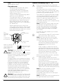
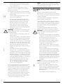
Plug replacement
• Disconnect the plug from the supply.
• Cut off the plug and dispose of
immediately. Insertion of a detatched
plug into a 13 amp socket outlet may
result in electric shock.
• Only fit BS1363A approved plugs fitted
with the correctly rated fuse.
• The cable wire colours, or a letter, will be
marked at the connection points of most
good quality plugs. Attach the wires to
their respective points in the plug (see
below). Brown is for “Live” (L) and blue is
for “Neutral” (N).
• Before replacing the top cover of the
mains plug ensure that the cable restraint
is holding the outer sheath on the cable
firmly and that the two leads are correctly
fixed at the terminal screws.
Fit a
BS1363A
approved
plug
Fit the
recommended
fuse
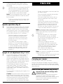
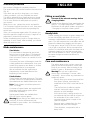
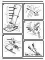
Handle assembly (Fig. A - D)
A
B
Connect blue
to N (neutral)
Connect brown
to L (live)
Make sure that the
outer sheath of the
cable is held firmly
by the clamp
!
!
4
240 volts AC only.
Never use a light
socket
Warning! Never connect live or neutral wires
to the earth pin marked “E” or
.
Note: Do not wire an extension cable directly
into your mower yourself. Instead, take your
mower to your nearest Black & Decker
service agent.
Increased safety can be obtained by having
a qualified electrician install a high sensitivity
(30mA) circuit breaker in the house wiring.
If you do not have such a circuit breaker
installed, or you do not wish to have one
installed, then we strongly recommend that
the electrical power to your mower be
supplied through a high sensitivity residual
current device (RCD). The RCD is designed
to provide a high degree of personal
protection against harmful electric current
should fault conditions occur.
Warning! The use of an RCD or other circuit
breaker unit does not release the operator of
your mower from the safety instructions and
safe working practices given in this manual.
C
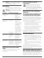
Remove all the parts from the carton and
familiarise yourself with the individual parts of
your mower.
The main parts of your mower are your
mower body (1) which comprises the cutter
cover (2), motor cover (3), air vent shroud (5),
pivot blocks (6) and pivot pins (8).
The handle (10) comprises the lower handle
(11), the upper handle (12), switch box (13)
with switch lever (14) and safety lock-off
switch (15), electrical supply cable (16), the
cable clips (17), and the handle clamp
assemblies (18) which each comprise a wing
nut, washer and bolt.
Note: The electrical supply cable should be
positioned on the right-hand side of your
mower when viewed from the operating
position. Ensure that this is not damaged
or twisted before you begin to assemble
your mower.
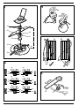
Assemble the lower handle to your mower
body, as follows:
• Place the lower handle (11) into the pivot
blocks (6) on the cutter cover (2).
Note: It will be necessary to tilt the lower
handle towards the rear of your mower to
allow pivot pins (8) to fit correctly.
• Fit the pivot pins (8) through the holes in
the pivot block flanges (6) and through
the holes in the lugs on the lower
handle (11).
• Using a mallet, or similar tool, tap the
pivot pin (8) through the inner part of the
pivot block (6). The hooks on the end of
the pivot pin will click into position behind
the inner wall, retaining it in position.
• Repeat the process on the other side.
With the lower handle in position, assemble
the upper handle, as follows:
• Place the upper handle (12) over the
lower handle (11). Ensure the upper bend
is as shown in Fig. A.
• Align the holes in both the upper and
lower handles and fit a bolt (20) through
each hole. Fit a washer (21) to each bolt
and fit the wing nuts (22) on to the bolts.
Tighten each one with hand pressure only.
Note: Do not use a spanner or other
implement to tighten the wing nuts.
With the upper and lower handles
assembled, fit the switch box to the upper
handle, as follows:
Note: The switch box must be positioned on
the right-hand side of your mower.