1
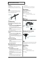
Owner's Manual
Thank you, and congratulations on your choice of the TD-8KV Roland Drum
System.
Before using this unit, carefully read the sections entitled: “USING THE
UNIT SAFELY” (p. 2–3) and “IMPORTANT NOTES” (p. 4). These sections
provide important information concerning the proper operation of the
unit. Additionally, in order to feel assured that you have gained a good
grasp of every feature provided by your new unit, Owner’s manual
should be read in its entirety. The manual should be saved and kept on
hand as a convenient reference.
Copyright © 2001 ROLAND CORPORATION
All rights reserved. No part of this publication may be reproduced in any
form without the written permission of ROLAND CORPORATION.
USING THE UNIT SAFELY
The
symbol alerts the user to important instructions
or warnings.The specific meaning of the symbol is
determined by the design contained within the
triangle. In the case of the symbol at left, it is used for
general cautions, warnings, or alerts to danger.
Used for instructions intended to alert
the user to the risk of death or severe
injury should the unit be used
improperly.
Used for instructions intended to alert
the user to the risk of injury or material
damage should the unit be used
improperly.
* Material damage refers
other adverse effects
respect to the home
furnishings, as well
animals or pets.
The
symbol alerts the user to items that must never
be carried out (are forbidden). The specific thing that
must not be done is indicated by the design contained
within the circle. In the case of the symbol at left, it
means that the unit must never be disassembled.
to damage or
caused with
and all its
to domestic
The ● symbol alerts the user to things that must be
carried out. The specific thing that must be done is
indicated by the design contained within the circle. In
the case of the symbol at left, it means that the powercord plug must be unplugged from the outlet.
001
005
002d
006
• Before using this unit, make sure to read the
instructions below, and the Owner’s Manual.
................................................................................................
• Do not open or perform any internal modifications on the unit or its AC adaptor. (The
only exception would be where this manual
provides specific instructions which should
be followed in order to put in place userinstallable options; see p. 7, p. 8.)
................................................................................................
003
• Do not attempt to repair the unit, or replace
parts within it (except when this manual
provides specific instructions directing you
to do so). Refer all servicing to your retailer,
the nearest Roland Service Center, or an
authorized Roland distributor, as listed on
the “Information” page.
................................................................................................
004
• Never use or store the unit in places that are:
• Subject to temperature extremes (e.g.,
direct sunlight in an enclosed vehicle, near
a heating duct, on top of heat-generating
equipment); or are
• Damp (e.g., baths, washrooms, on wet
floors); or are
• Humid; or are
• Exposed to rain; or are
• Dusty; or are
• Subject to high levels of vibration.
................................................................................................
2
• This unit should be used only with a rack or
stand that is recommended by Roland.
................................................................................................
• When using the unit with a rack or stand
recommended by Roland, the rack or stand
must be carefully placed so it is level and
sure to remain stable. If not using a rack or
stand, you still need to make sure that any
location you choose for placing the unit
provides a level surface that will properly
support the unit, and keep it from wobbling.
................................................................................................
011
• Do not allow any objects (e.g., flammable
material, coins, pins); or liquids of any kind
(water, soft drinks, etc.) to penetrate the unit.
................................................................................................
013
• In households with small children, an adult
should provide supervision until the child is
capable of following all the rules essential for
the safe operation of the unit.
................................................................................................
• To prevent accidents, never allow small
children to play near the drum kit.
................................................................................................
014
• Do not drop the unit!
................................................................................................
• To avoid personal injury and/or damage to
the unit, do not touch anything inside the
frame of the PD-80 and PD-80R.
................................................................................................
104
• Try to prevent cords and cables from
becoming entangled. Also, all cords and
cables should be placed so they are out of the
reach of children.
................................................................................................
106
• Never climb on top of, nor place heavy
objects on the unit.
................................................................................................
118
• Should you remove screws, nuts, bolts,
springs, washers, etc., make sure to put them
in a safe place out of children's reach, so there
is no chance of them being swallowed
accidentally.
................................................................................................
• Assemble the drum stand and TD-8KV
carefully, to avoid pinching your fingers.
................................................................................................
• Make sure to firmly tighten all clamps and
bolts after you have assembled the stand and
attached a pad or unit to it. You should
probably also try to make a habit of checking
and retightening them if necessary before
every performance. You risk injury if you
have loose screws or clamps, since a pad or
unit can fall unexpectedly.
................................................................................................
• Be sure to tighten the head tension before
using the KD-80, PD-80R, and PD-80. Striking
the head when the head tension is loose may
damage the sensor and head.
................................................................................................
• Do not apply excessive force to the sensor
(and on the KD-80, the cushion) located
below the center of the head of the KD-80,
PD-80R, and PD-80. Doing so can interfere
with accurate detection, and may damage it.
................................................................................................
• Due to the nature of the materials used in the
sensor of the KD-80, PD-80R, and PD-80,
changes in room temperature may affect the
sensitivity of the sensor.
................................................................................................
• Please be aware that by using a felt beater for
the KD-80, you risk causing damage to the
head as a result of the metal portions of the
beater that can become exposed when the felt
wears thin. For the kick pedal, we
recommend that you use only the supplied
beater, or a commercially available plastic
beater.
................................................................................................
• To keep the KD-80 and FD-6 from slipping or
moving during play, the tips of the legs
installed on the stand and the tips of the
anchor bolts are pointed. Handle with care to
avoid injury.
................................................................................................
• Brushes can be used to play the PD-80R and
PD-80. When using brushes, be sure to use
nylon brushes. Using metal brushes will not
only scratch the head, but can also be
hazardous, since the tip of the brush may
catch in the mesh of the net.
................................................................................................
• The rubber portion of the PD-80R’s hoop is
one component that eventually wears out
(the more so if numerous rim shots are
performed), and will require replacement.
Errors may occur when attempting rim shots
once the rubber portion has worn out. If this
occurs, replace the hoop rubber. For more on
replacing the hoop rubber, consult with your
retailer, the nearest Roland Service Center, or
an authorized Roland distributor, as listed on
the “Information” page.
................................................................................................
3
IMPORTANT NOTES
291a
In addition to the items listed under “USING THE UNIT SAFELY” on page 2–3, please read and observe the
following:
Placement
Additional Precautions
354a
553
• Do not expose the unit to direct sunlight, place it
near devices that radiate heat, leave it inside an
enclosed vehicle, or otherwise subject it to temperature extremes. Excessive heat can deform or
discolor the unit.
• Use a reasonable amount of care when using the
unit’s buttons, sliders, or other controls; and when
using its jacks and connectors. Rough handling can
lead to malfunctions.
556
• To avoid possible breakdown, do not use the unit in
a wet area, such as an area exposed to rain or other
moisture.
• When connecting / disconnecting all cables, grasp
the connector itself—never pull on the cable. This
way you will avoid causing shorts, or damage to the
cable’s internal elements.
356
558a
355
• Do not allow rubber, vinyl, or similar materials to
remain on the unit for long periods of time. Such
objects can discolor or otherwise harmfully affect the
finish.
357
• Do not put anything that contains water (e.g., flower
vases) on the unit. Also, avoid the use of insecticides, perfumes, alcohol, nail polish, spray cans, etc.,
near the unit. Swiftly wipe away any liquid that
spills on the unit using a dry, soft cloth.
Maintenance
401a
• For everyday cleaning wipe the unit with a soft, dry
cloth or one that has been slightly dampened with
water. To remove stubborn dirt, use a cloth impregnated with a mild, non-abrasive detergent. Afterwards, be sure to wipe the unit thoroughly with a
soft, dry cloth.
402
• Never use benzine, thinners, alcohol or solvents of
any kind, to avoid the possibility of discoloration
and/or deformation.
4
• To avoid disturbing your neighbors, try to keep the
unit’s volume at reasonable levels. You may prefer
to use headphones, so you do not need to be
concerned about those around you (especially when
it is late at night).
558d
• This instrument is designed to minimize the extraneous sounds produced when it’s played. However,
since sound vibrations can be transmitted through
floors and walls to a greater degree than expected,
take care not to allow these sounds to become a
nuisance to neighbors, especially when performing
at night and when using headphones.
562
• Use a provided cable or a cable from Roland to make
the connection. If using some other make of
connection cable, please note the following precautions.
• Some connection cables contain resistors. Do not
use cables that incorporate resistors for
connecting to this unit. The use of such cables can
cause the sound level to be extremely low, or
impossible to hear. For information on cable
specifications, contact the manufacturer of the
cable.
Getting Started
Check the Contents of the
Box
❑ TD-8 (Percussion Sound Module) x 1
❑ KD-80 (V-Kick Trigger) x 1
• The TD-8 Owner’s Manual is included in the TD-8
package.
962a
In the interest of product improvement, the specifications
and/or appearance of this unit are subject to change without
prior notice.
❑ FD-6 (Hi-Hat Control Pedal) x 1
❑ PD-80R (V-Pad) x 1
Setup Procedure
❑ PD-80 (V-Pad) x 3
❑ CY-12R/C (V-Cymbal) X 2
1. Assemble the drum stand.
❑ PD-7 (Pad) x 1
❑ Accessory Set x 1
❏ Tuning Key
(for KD-80, PD-80R,
PD-80, CY-12R/C, and FD-6) x 1
❏ Beater (for KD-80) x 1
For more information on assembling the stand, refer to
the owner's manual for the stand.
2. Adjust the head tension of the KD-80, PD-80R, and
PD-80 (p. 6).
❏ Wing Nut (for CY-12R/C) x 2
3. Set up the pads, cymbals and pedals.
• KD-80 (Kick) → p. 8
• PD-80R (Snare)/PD-80 (Tom-Tom) → p. 10
• CY-12R/C (Ride, Crash) → p. 10
• PD-7 (Hi-Hat) → p. 12
• FD-6 (Hi-Hat Control Pedal) → p. 13
• TD-8 (Percussion Sound Module) → p. 13
❏ Felt Washer (for CY-12R/C) x 2
4. Connect all pads and the like to the TD-8 (p. 14).
❏ Anchor Bolt (for FD-6) x 2
❏ Spring for Anchor Bolt (for FD-6) x 2
❏ Stopper (for CY-12R/C) x 2
❏ Cable Tie (fir CY-12R/C) x 2
❑ Connection Cable Set x 1
❑ Connection Cable (1 meter) x 2
(for Hi-Hat: PD-7/Snare: PD-80R)
❑ Connection Cable (2 meters) x 5
(for Kick: KD-80/Tom1, 2: PD-80 x 2/
Hi-Hat Control Pedal: FD-6/Crash: CY-12R/C)
❑ Connection Cable (3.5 meters) x 2
(for Tom3: PD-80/Ride: CY-12R/C)
■ TD-8KV Owner’s Manual (this manual) x 1
• This package does not include a drum stand. Please use
the separately available drum stand (MDS series).
• This package does not include a kick pedal. Use with a
commercially available kick pedal.
5
About the Mesh Head
Adjusting the Head Tension
The KD-80, PD-80R, and PD-80 are shipped
from the factory with the head tension
loosened. Be sure to adjust the tension
before use.
1. Use the included tuning key to tighten the tuning
bolts.
Tighten the bolts until you achieve the correct amount of
space between the frame and the hoop, which is:
KD-80: approximately 7.5 mm
PD-80R/PD-80: approximately 7 mm
KD-80
In general, a tension that produces a strike response
approximately the same as an acoustic drum will be
appropriate.
Hoop
Frame
•
•
Striking the head when the head tension is loose
may damage the sensor and head.
Should you neglect to make the appropriate
settings, you could likely experience the
following problems:
Sometimes it does not sound (uneven volume).
The volume is too low (reduced sensitivity).
• On the KD-80, PD-80R, and PD-80, adjusting the head
tension affects only the head response, and does not
change the pitch of the sound, as it would on an acoustic
drum.
• The head tension will change as the instrument is used,
so you should readjust when necessary.
• The head stretches when used for extended periods, so
even when properly adjusted to 7.5 mm (KD-80), or 7 mm
(PD-80R and PD-80) by means of the following
procedure, you may not achieve the same degree of
tension as when the head was initially adjusted. Strike
the head to check the feel and response as you adjust the
tension.
• Tighten each tuning bolt one by one, observing the
numerical order shown in the diagram.
Do not firmly tighten a single tuning bolt by itself. Doing
so will make it impossible to tension the head evenly, and
will cause malfunctions.
7.5 mm
PD-80R/PD-80
Hoop
7 mm
Frame
Black strips, one 7.5 mm in length and the other 7 mm,
are printed at the edge of this page. Use these for
reference when making the adjustment.
fig.K08.e
2. Fine-tune the adjustment while continuing to check
the pad feel and response.
6
These strips are 7.5 mm and 7 mm
in length. Use them for adjusting
the head tension.
7.5 mm
7 mm
1
4
3
2
5
About the Mesh Head
Replacing the Head
6. Pass the tuning bolts through the washers, then
attach them to the hoop and frame.
When the Head Should Be
Replaced
7. Next, adjust the tension of the head. Refer to
“Adjusting the Head Tension” (p. 6).
The head is an expendable item that eventually will wear out
and need to be replaced. Replace the head when the following
occurs:
• The head surface is torn
• Striking points are no longer detected correctly, even
when the head tension is properly adjusted.
• Slack portions remain in the head even after the head
tension is properly adjusted.
Do not firmly tighten a single tuning bolt by itself. Doing so
will make it impossible to tension the head evenly, and will
cause malfunctions such as failure to accurately detect the
striking location.
Replacement heads (optional)
MH-8 Mesh Head: for either KD-80, PD-80R or PD-80
Replacing the Head
1. Remove all tuning bolts and washers.
When replacing the head of the KD-80 or the PD-80R,
press the lock bushing (in figure below) in place with
your finger as you remove each tuning bolt, to prevent
the bushings from being pulled off the frame.
Only the KD-80 and the PD-80R are provided with lock
bushings.
About the Lock Bushings
The KD-80 and the PD-80R are provided with lock bushings to
prevent rotation and loosening of the tuning bolts caused by
vibration transmitted from the hoop.
If a lock bushing happens to become separated from the frame
while the head is being replaced, position the bushing so its
four slots are aligned with the corresponding ridges in the
frame, then press down firmly on the bushing.
Lock Bushing
Frame
Tuning Key
Tuning Bolt
Washer
Hoop
Lock Bushing
Frame
For more on the lock bushings, refer to the following
section, “About the Lock Bushings.”
2. Remove the hoop.
3. Remove the old head.
4. Place the new head on the frame.
5. Place the hoop onto the head.
7
Setting Pads and Pedals
KD-80
3. Mount the stay on the pad.
(V-Kick Trigger)
Align the mark on the stay with the protrusion of the
bracket, and use the tuning key to firmly tighten the bolts
that you loosened in step 2.
Before using the KD-80, you need to adjust the head tension
(p. 6).
Align the marks
Hoop
Tuning Bolt
Bolt
Head
Cushion
Sensor
T-bolt
Leg
Stand
Rubber
Foot
Foot
4. Loosen the leg nut.
Frame
Output Jack
5. Rotate the rubber foot to adjust the leg tip.
Stay
Bracket
Adjust to use the spike legs when installing on carpeting
or other soft surfaces, or the rubber legs when installing on
flooring or other hard surfaces.
When shipped from the factory, the stand is adjusted for
using the rubber legs.
Spike Leg
Rubber Leg
Nut
Assembling the KD-80
• Take care not to pinch your fingers between the KD-80
pad and the stand plate.
• Please be aware that by using a felt beater, you risk
causing damage to the head as a result of the metal
portions of the beater that can become exposed when the
felt wears thin. For the kick pedal, we recommend that
you use only the supplied beater, or a commercially
available plastic beater.
1. Place the KD-80 pad, with the head surface facing
downward, on a flat surface such as the floor.
2. Use the included tuning key to loosen the bolts for
the bracket on the back of the KD-80 pad, then
open the bracket.
8
Spike
Rubber Foot
• The tip of the spike is sharp. Handle it with care.
• When using on flooring, the spike legs may damage the
floor. Adjust to use the rubber legs.
6. Tighten the nut and rubber foot to secure the
rubber foot in place and keep it from loosening.
The nut and rubber foot must be tighten to prevent the
malfunctions.
KD-80 (V-Kick Trigger)
7. Loosen the T-bolts for the stay and mount the legs
on the stay.
Install the legs as shown in the figure so that the ends of
the legs protrude by about 1 inch (2 cm).
fig.K05.e
If you are using a kick pedal with an under plate
Adjust the length of the legs so that the four legs of the
KD-80 and the heel of the kick pedal contact the floor
evenly.
13. Adjust the striking point for the beater.
The beater's striking point is adjusted to fall at the center
of the head.
Adjust the striking point so that it doesn't extend beyond
the cushion on the back of the head.
When Using a Twin (Double Kick) Pedal
Extend the leg
by about 1 inch
(2 cm).
With the KD-80, you can also play using a twin (double kick)
pedal.
Set this up so the striking points of the two beaters fall at equal
distances to the left and right of the center of the head.
8. Tighten the T-bolts to secure the legs to the stand.
9. Lift the KD-80 and place the stand and the four legs
upright.
When using a twin (double kick) pedal, as with a regular
pedal, use the included beater or a plastic beater as the beater
for the kick pedal.
fig.K07
10. Adjust the angle of the stand plate so that it's at a
right angle to the floor.
Loosen the T bolts that you tightened in step 8, and adjust
the length of the legs so that the stand plate is vertical to
the floor. Then firmly tighten the T bolts.
11. Install the included beater on your kick pedal.
12. Mount the kick pedal on the KD-80.
fig.K06.e
Specifications
Adjust
the leg length
Under plate
Stand plate
Heel portion
60°
90°
KD-80: V-Kick Trigger
Pad Size: 8 inches
Trigger: 1
Dimensions: 440 (W) x 340 (D) x 465 (H) mm
17-3/8 (W) x 13-7/16 (D) x 18-5/16 (H) inches
Weight: 4.8 kg
10 lbs 10 oz
• Install the kick pedal securely.
• Set the KD-80 so no mechanical noise is heard when you
step on pedal.
• Make sure that KD-80 does not touch the drum stand or
the other pads.
9
PD-80R/PD-80 (V-Pad) / CY-12R/C (V-Cymbal)
PD-80R/PD-80
Adjustment for Positional Sensing
with the TD-8
(V-Pad)
Before using the PD-80R and the PD-80, you need to adjust the
head tension (p. 6).
fig.P01.j
When the TD-8 is used as the sound module, the location at which
the pad is struck can be varied to produce tonal changes. In this
case, it is important to adjust the head so the tension is evenly
distributed, so the striking location can be detected accurately.
For details on adjustments, refer to the TD-8 owner's manual.
Hoop (Rim)
Stand
Fixing Screw
Sensor
The positional sensing function works only with TD-8’s
trigger input 3 (SNARE).
Head
Specifications
Washer
Tuning Bolt
Output Jack
Holder
Frame
Attaching the Pad to a Stand
Attach the PD-80R or PD-80 to a stand (MDS series).
fig.P02.j
Tighten
PD-80R: V-Pad
Pad Size: 8 inches
Trigger: 2 (Head, Rim)
Dimensions: 245 (W) x 310 (D) x 95 (H) mm
9-11/16 (W) x 12-1/4 (D) x 3-3/4 (H) inches
Weight: 1.7 kg
3 lbs 11 oz
PD-80: V-Pad
Pad Size: 8 inches
Trigger: 1 (Head)
Dimensions: 245 (W) x 310 (D) x 95 (H) mm
9-11/16 (W) x 12-1/4 (D) x 3-3/4 (H) inches
Weight: 1.6 kg
3 lbs 8 oz
CY-12R/C
(V-Cymbal)
Bell
Loosen
Bow
Edge
Rod
Pass the rod through the pipe
that is inside the holder.
When attaching the PD-80R and the PD-80 to the pad mount,
be sure to tighten the stand fixing screw securely. If any of
them remain loose, the pad could fall off.
BOW/BELL
Output Jack
BOW/EDGE
Output Jack
Attaching the V-Cymbal to the
Cymbal Mount
Attach the CY-12R/C to the cymbal mount of a drum stand
(MDS series).
1. Use the included tuning key to tighten the stopper bolt.
The stopper keeps the CY-12R/C from turning, and
10
CY-12R/C (V-Cymbal)
prevents the cables from catching or getting tangle on the
stand.
fig.CY-03.e
Playing the CY-12R/C
Bow Shot
Stopper
(Be sure to
orient it correctly.)
Tighten the bolt with
the included tuning key.
This is the most common playing method, playing the pad face
of the cymbal. It corresponds to the sound of the “head-side” of
the connected trigger input.
Bow
2. Attach the CY-12R/C so the unit is oriented as
shown in the diagram (bolt should be opposite the
output jacks).
3. Tighten the wing nut to obtain the desired
movement.
Use the included felt washer and the wing nut.
Edge Shot
This playing method involves striking the edge with the
shoulder of the stick. It corresponds to the sound of the “rimside” of the connected trigger input.
fig.CY04.e
Wing Nut
Felt Washer
To make use of edge shot, you'll need to connect to a trigger
input jack on the percussion sound module that
accommodates rim shots.
Edge Sensor
• Double sounding may occur if the wing nut is loose.
• Do not use the washer or felt included with the drum
stand (MDS series).
About the Output Jacks
The CY-12R/C features two different output jacks, BOW/BELL
and BOW/EDGE.
Use the BOW/BELL output jack when you want to play the
bow and the bell sounds (used as a ride cymbal); use the BOW/
EDGE output jack when you want to play the bow and the edge
sounds (used as a crash cymbal).
Use either the BOW/BELL or BOW/EGDE output jack, but
not both at the same time. Connecting both jacks results in two
separate trigger inputs playing simultaneously.
Output Jack
BOW/BELL
BOW/EDGE
Corresponding
Play Methods
Bow Shot (p. 11)
Bell Shot (p. 11)
Choke (p. 12)
Bow Shot (p. 11)
Edge Shot (p. 11)
Choke (p. 12)
Bell Shot
This playing method involves striking the bell. It corresponds
to the sound of the “rim-side” of the connected trigger input.
• To make use of bell shot, you'll need to connect to a
trigger input jack on the percussion sound module that
accommodates rim shots.
• Use the shoulder of the stick when playing bell shots.
Bell
Tones Sounded
Head
Rim
–
Head
Rim
–
11
CY-12R/C (V-Cymbal) / PD-7 (Pad)
Choking
Choking (pinching) the cymbal’s edge with the hand
immediately after hitting the cymbal makes the sound stop.
properly (p. 10).
*
If double triggering still occurs, try adjusting trigger
parameters, such as Retrigger Cancel, on your TD-8.
Specifications
To make use of choking play techniques, you’ll need to
connect to a trigger input jack on the percussion sound
module that accommodates rim shots.
f
Edge Sensor
CY-12R/C: V-Cymbal Ride/Crash
Pad Size: 12 inches
Trigger: 3 (Bow, Bell, Edge)
Dimensions: 300 (W) x 300 (D) x 51 (H)
11-13/16 (W) x 11-13/16 (W) x 2-1/16 (H)
Weight: 1.1 kg
2 lbs 7 oz
PD-7
Troubleshooting
(Pad)
Head
Holder
Rim
The sound does not change when an edge
shot is made
• Is the cable connected to the BOW/EDGE output?
Make the connection to the BOW/EDGE output to enable
the CY-12R/C to support edge shots (p. 11).
• Are you striking the cymbal in the area with the edge
sensors?
Edge sensors are embedded only in the part of the CY12R/C directly in front (p. 11).
The sound does not change when a bell shot
is made
Stand Fixing
Screw
Output Jack
“– (Roland)” position
Attaching the Pad to a Stand
Attach the PD-7 to a stand (MDS series).
• Is the cable connected to the BOW/BELL output?
Make the connection to the BOW/BELL output to enable
the CY-12R/C to support bell shots (p. 11).
• Use the shoulder of the stick when playing bell shots
(p. 11).
• Adjust the “Scan Time.”
Choke play is not possible
• Are you choking the cymbal in the area with the edge
sensors?
Edge sensors are embedded only in the part of the CY12R/C directly in front (p. 12).
Ride cymbal sounds odd
(Other cymbal sound is heard simultaneously)
• Connect either the CY-12R/C’s Bow/Bell output or the
Bow/Edge output to the TD-8 (p. 11).
Double sounding
• Are any cables touching the CY-12R/C?
Secure the cables in place with the cable ties so that they
do not touch the units. Also, be careful to make sure that
the cables are not pulled by the movement of a cymbal
when struck (p. 15).
• Are the stopper, felt washer, and wing nut attached
correctly?
Double triggering may occur if the stopper and/or wing
nut is loose. Use a tuning key (drum key) to tighten
12
Polarity Switch
Pass the rod through the eyebolt.
Eyebolt
Rod
When attaching the PD-7 to the pad mount, be sure to tighten
the stand fixing screw securely. If any of them remain loose,
the pad could fall off.
Specifications
PD-7: Pad
Pad Size: 7.5 inches
Trigger: 2 (Head, Rim)
Dimensions: 192 (W) x 230 (D) x 65 (H)
7-9/16 (W) x 9-1/16 (W) x 2-9/16 (H)
Weight: 0.8 kg
1 lb 13 oz
FD-6 (Hi-Hat Control Pedal)/TD-8 (Percussion Sound Module)
FD-6
(Hi-Hat Control Pedal)
Adjusting the Travel of the Pedal
deep
TD-8
(Percussion Sound Module)
Attach the stand holder (included with the drum stand) to the
TD-8.
fig.TD01.e
Shift the Arm
shallow
Loosen the bolt with the included tuning
key. After adjusting, tighten the bolt.
Narrow
Pedal Plate
Wide
Control Out Jack
Attaching the Anchor Bolts
(When Using on the Carpet)
Anchor Bolt
Spring for
the Anchor Bolt
• To attach the stand holder, remove the four 12 mm
screws (M5 x 12) from the bottom of the TD-8 and use
them. Use of other screws may result in damage to the
unit.
• When turning the unit upside-down, get a bunch of
newspapers or magazines, and place them under the four
corners or at both ends to prevent damage to the buttons
and controls. Also, you should try to orient the unit so no
buttons or controls get damaged.
• When turning the unit upside-down, handle with care to
avoid dropping it, or allowing it to fall or tip over.
• The tips of the anchor bolts are sharp. Handle with care.
• When using on flooring, the anchor bolts may damage
the floor. Do not attach the anchor bolts.
• When the FD-6 is not going to be used for a long period
of time, move and fix the arm, allowing longer travel for
the pedal.
• To avoid damage, do not leave the FD-6 for extended
periods of time with the pedal plate depressed.
The TD-8 owner's manual assumes use of the FD-7 Hi-Hat
Control Pedal. For each instance in which you find “FD-7”
mentioned in the TD-8 owner's manual, please substitute the
name “FD-6.”
Specifications
FD-6: Hi-Hat Control Pedal
Dimensions: 160 (W) x 395 (D) x 120 (H) mm
6-5/16 (W) x 15-9/16 (D) x 4-3/4 (H) inches
Weight: 1.4 kg
3 lbs 2 oz (including anchor bolts)
13
Connect the pads and pedals to the TD-8
To prevent malfunction and/or damage to speakers or other devices, always turn down the volume, and turn off the power on all
devices before making any connections.
fig.KIT01.e
Crash
CY-12R/C
Ride
CY-12R/C
Tom 1
PD-80
TD-8
Hi-Hat
PD-7
Tom 2
PD-80
Kick
KD-80
Snare
PD-80R
Hi-Hat Control Pedal
FD-6
14
Tom 3
PD-80
Connect the pads and pedals to the TD-8
About the Included Cables
Connecting the CY-12R/C
Using the provided cables, connect the pads and pedals to the
TD-8.
• Carefully refer to the numbers shown in the illustration
and connect to the appropriate TRIGGER INPUT jacks on
the TD-8’s rear panel.
• Connect the L-shaped plug of the included cable to the
pad.This will prevent strain from being applied to the
pad.
1. Use the included cable to connect one of the CY12R/C’s output jacks (either one, but not both) to
the TD-8's trigger input jack.
2m
3.5 m
If the CY-12R/C is to be used as a crash cymbal,
connect it to the BOW/EDGE output jack; if it is to be
used as a ride cymbal, connect it to the BOW/BELL
output jack.
2. Secure the cable with cable ties.
Secure the cables in place with the cable tie, while leaving
some slack in the cables to ensure that they are not pulled
by the movement of the cymbal units when struck.
fig.CY04.e
Wind the cable
tie twice
Leave
some slack
Tighten it not to slip
Turn back
to fix the cable
1m
Secure the cable
with the cable tie
Take care to ensure that the cables do not touch the
cymbal units and/or the stand. A cable touching a
cymbal unit or a stand may cause double sounding or
other incorrect operation.
When you have finished making the connections, proceed with the
TD-8's settings.
Settings optimized for the TD-8KV are provided in factory settings on the TD-8 (Trigger Bank 1).
1. Press [SETUP] → [F1 (TRIG)].
2. Check to see if you have things set as shown in the screen below.
3. If your settings are different, make the trigger settings as described in the owner's manual provided with
the TD-8.
15
Information
When you need repair service, call your nearest Roland Service Center or authorized Roland distributor in your country as
shown below.
AFRICA
EGYPT
Al Fanny Trading Office
9, EBN Hagar A1 Askalany Street,
ARD E1 Golf, Heliopolis,
Cairo 11341, EGYPT
TEL: 20-2-417-1828
REUNION
Maison FO - YAM Marcel
25 Rue Jules Hermann,
Chaudron - BP79 97 491
Ste Clotilde Cedex,
REUNION ISLAND
TEL: (0262) 218-429
SINGAPORE
Swee Lee Company
150 Sims Drive,
SINGAPORE 387381
TEL: 6846-3676
CRISTOFORI MUSIC PTE
LTD
Blk 3014, Bedok Industrial Park E,
#02-2148, SINGAPORE 489980
TEL: 6243-9555
P.O.BOX 23032, Claremont 7735,
SOUTH AFRICA
TEL: (021) 674 4030
ASIA
CHINA
Roland Shanghai Electronics
Co.,Ltd.
5F. No.1500 Pingliang Road
Shanghai, CHINA
TEL: (021) 5580-0800
Roland Shanghai Electronics
Co.,Ltd.
(BEIJING OFFICE)
10F. No.18 Anhuaxili
Chaoyang District, Beijing,
CHINA
TEL: (010) 6426-5050
HONG KONG
Tom Lee Music Co., Ltd.
Service Division
22-32 Pun Shan Street, Tsuen
Wan, New Territories,
HONG KONG
TEL: 2415 0911
INDIA
Rivera Digitec (India) Pvt. Ltd.
409, Nirman Kendra Mahalaxmi
Flats Compound Off. Dr. Edwin
Moses Road, Mumbai-400011,
INDIA
TEL: (022) 2493 9051
INDONESIA
Easa Husain Al Yousifi Est.
UL. Gibraltarska 4.
PL-03664 Warszawa POLAND
TEL: (022) 679 44 19
Theera Music Co. , Ltd.
VENEZUELA
330 Verng NakornKasem, Soi 2,
Bangkok 10100, THAILAND
TEL: (02) 2248821
Musicland Digital C.A.
Tecnologias Musica e Audio,
Roland Portugal, S.A.
VIETNAM
Saigon Music
138 Tran Quang Khai St.,
District 1
Ho Chi Minh City
VIETNAM
TEL: (08) 844-4068
AUSTRALIA/
NEW ZEALAND
AUSTRALIA
Roland Corporation
Australia Pty., Ltd.
38 Campbell Avenue
Dee Why West. NSW 2099
AUSTRALIA
TEL: (02) 9982 8266
NEW ZEALAND
Roland Corporation Ltd.
32 Shaddock Street, Mount Eden,
Auckland, NEW ZEALAND
TEL: (09) 3098 715
CENTRAL/LATIN
AMERICA
ARGENTINA
Instrumentos Musicales S.A.
Av.Santa Fe 2055
(1123) Buenos Aires
ARGENTINA
TEL: (011) 4508-2700
EUROPE
AUSTRIA
DENMARK
Roland Scandinavia A/S
Nordhavnsvej 7, Postbox 880,
DK-2100 Copenhagen
DENMARK
TEL: 3916 6200
FRANCE
Roland France SA
4, Rue Paul Henri SPAAK,
Parc de l'Esplanade, F 77 462 St.
Thibault, Lagny Cedex FRANCE
TEL: 01 600 73 500
FINLAND
Ave.1. Calle 11, Apartado 10237,
San Jose, COSTA RICA
TEL: 258-0211
1461-9, Seocho-Dong,
Seocho Ku, Seoul, KOREA
TEL: (02) 3486-8855
Comercial Fancy
S.A.
Rut.: 96.919.420-1
Nataniel Cox #739, 4th Floor
Santiago - Centro, CHILE
TEL: (02) 688-9540
EL SALVADOR
OMNI MUSIC
75 Avenida Norte y Final
Alameda Juan Pablo ,
Edificio No.4010 San Salvador,
EL SALVADOR
TEL: 262-0788
MEXICO
Casa Veerkamp, s.a. de c.v.
Av. Toluca No. 323, Col. Olivar
de los Padres 01780 Mexico D.F.
MEXICO
TEL: (55) 5668-6699
GERMANY
Roland Elektronische
Musikinstrumente HmbH.
Oststrasse 96, 22844 Norderstedt,
GERMANY
TEL: (040) 52 60090
GREECE
STOLLAS S.A.
Music Sound Light
155, New National Road
Patras 26442, GREECE
TEL: 2610 435400
HUNGARY
Piata Libertatii 1,
RO-4200 Gheorghehi
TEL: (095) 169-5043
3-Bogatyrskaya Str. 1.k.l
107 564 Moscow, RUSSIA
TEL: (095) 169 5043
SPAIN
Roland Electronics
de España, S. A.
Calle Bolivia 239, 08020
Barcelona, SPAIN
TEL: (93) 308 1000
SWEDEN
Roland Scandinavia A/S
SWEDISH SALES OFFICE
SAUDI ARABIA
aDawliah Universal
Electronics APL
Corniche Road, Aldossary Bldg.,
1st Floor, Alkhobar,
SAUDI ARABIA
P.O.Box 2154, Alkhobar 31952
SAUDI ARABIA
TEL: (03) 898 2081
SYRIA
Technical Light & Sound
Center
Khaled Ebn Al Walid St.
Bldg. No. 47, P.O.BOX 13520,
Damascus, SYRIA
TEL: (011) 223-5384
TURKEY
SWITZERLAND
Barkat muzik aletleri ithalat
ve ihracat Ltd Sti
Roland (Switzerland) AG
Landstrasse 5, Postfach,
CH-4452 Itingen,
SWITZERLAND
TEL: (061) 927-8383
UKRAINE
TIC-TAC
Mira Str. 19/108
P.O. Box 180
295400 Munkachevo, UKRAINE
TEL: (03131) 414-40
UNITED KINGDOM
Roland (U.K.) Ltd.
Atlantic Close, Swansea
Enterprise Park, SWANSEA
SA7 9FJ,
UNITED KINGDOM
TEL: (01792) 702701
MIDDLE EAST
BAHRAIN
Moon Stores
IRELAND
CYPRUS
Audio House, Belmont Court,
Donnybrook, Dublin 4.
Republic of IRELAND
TEL: (01) 2603501
P.O. Box 62,
Doha, QATAR
TEL: 4423-554
Danvik Center 28, 2 tr.
S-131 30 Nacka SWEDEN
TEL: (0)8 702 00 20
Warehouse Area ‘DEPO’ Pf.83
H-2046 Torokbalint, HUNGARY
TEL: (23) 511011
Roland Ireland
Chahine S.A.L.
Gerge Zeidan St., Chahine Bldg.,
Achrafieh, P.O.Box: 16-5857
Beirut, LEBANON
TEL: (01) 20-1441
Al Emadi Co. (Badie Studio
& Stores)
FBS LINES
No.16, Bab Al Bahrain Avenue,
P.O.Box 247, Manama 304,
State of BAHRAIN
TEL: 211 005
Roland East Europe Ltd.
LEBANON
ROMANIA
MuTek
Houtstraat 3, B-2260, Oevel
(Westerlo) BELGIUM
TEL: (014) 575811
Abdullah Salem Street,
Safat, KUWAIT
TEL: 243-6399
QATAR
RUSSIA
BELGIUM/HOLLAND/
LUXEMBOURG
Roland Benelux N. V.
KUWAIT
Cais Das Pedras, 8/9-1 Dto
4050-465 PORTO
PORTUGAL
TEL: (022) 608 00 60
Siemensstrasse 4, P.O. Box 74,
A-6063 RUM, AUSTRIA
TEL: (0512) 26 44 260
Elannontie 5
FIN-01510 Vantaa, FINLAND
TEL: (0)9 68 24 020
Rua San Jose, 780 Sala B
Parque Industrial San Jose
Cotia - Sao Paulo - SP, BRAZIL
TEL: (011) 4615 5666
PORTUGAL
Roland Austria GES.M.B.H.
Roland Brasil Ltda
CHILE
339 Gil J. Puyat Avenue
Makati, Metro Manila 1200,
PHILIPPINES
TEL: (02) 899 9801
Av. Francisco de Miranda,
Centro Parque de Cristal, Nivel
C2 Local 20 Caracas
VENEZUELA
TEL: (212) 285-8586
Roland Scandinavia As,
Filial Finland
BRAZIL
Cosmos Corporation
PHILIPPINES
G.A. Yupangco & Co. Inc.
JORDAN
AMMAN Trading Agency
Francisco Acuna de Figueroa 1771
C.P.: 11.800
Montevideo, URUGUAY
TEL: (02) 924-2335
JUAN Bansbach
Instrumentos Musicales
140 & 142, Jalan Bukit Bintang
55100 Kuala Lumpur, MALAYSIA
TEL: (03) 2144-3333
Roland Scandinavia Avd.
Kontor Norge
P. P. H. Brzostowicz
COSTA RICA
BENTLEY MUSIC SDN BHD
NORWAY
Distribuidora De
Instrumentos Musicales
POLAND
J1. Cideng Timur No. 15J-150
Jakarta Pusat
INDONESIA
TEL: (021) 6324170
MALAYSIA
PARAGUAY
8 Retzif Ha'aliya Hashnya St.
Tel-Aviv-Yafo ISRAEL
TEL: (03) 6823666
Todo Musica S.A.
ROLAND TAIWAN
ENTERPRISE CO., LTD.
PT Citra IntiRama
KOREA
Halilit P. Greenspoon &
Sons Ltd.
URUGUAY
TAIWAN
THAILAND
17 Werdmuller Centre,
Main Road, Claremont 7708
SOUTH AFRICA
Viale delle Industrie 8,
20020 Arese, Milano, ITALY
TEL: (02) 937-78300
245 Prince Mohammad St.,
Amman 1118, JORDAN
TEL: (06) 464-1200
That Other Music Shop
(PTY) Ltd.
Paul Bothner (PTY) Ltd.
ISRAEL
Roland Italy S. p. A.
Boulevard Andrews, Albrook,
Panama City, REP. DE PANAMA
TEL: 315-0101
Lilleakerveien 2 Postboks 95
Lilleaker N-0216 Oslo
NORWAY
TEL: 2273 0074
SOUTH AFRICA
P.O.Box 32918, Braamfontein 2017
Johannesbourg, SOUTH AFRICA
TEL: (011) 403 4105
ITALY
SUPRO MUNDIAL, S.A.
J.E. Olear y ESQ. Manduvira
Asuncion PARAGUAY
TEL: (021) 492-124
Room 5, 9fl. No. 112 Chung Shan
N.Road Sec.2, Taipei, TAIWAN,
R.O.C.
TEL: (02) 2561 3339
11 Melle St., Braamfontein,
Johannesbourg, SOUTH AFRICA
PANAMA
Radex Sound Equipment Ltd.
17, Diagorou Street, Nicosia,
CYPRUS
TEL: (022) 66-9426
Siraselviler Caddesi Siraselviler
Pasaji No:74/20
Taksim - Istanbul, TURKEY
TEL: (0212) 2499324
U.A.E.
Zak Electronics & Musical
Instruments Co. L.L.C.
Zabeel Road, Al Sherooq Bldg.,
No. 14, Grand Floor, Dubai, U.A.E.
TEL: (04) 3360715
NORTH AMERICA
CANADA
Roland Canada Music Ltd.
(Head Office)
5480 Parkwood Way Richmond
B. C., V6V 2M4 CANADA
TEL: (604) 270 6626
Roland Canada Music Ltd.
(Toronto Office)
170 Admiral Boulevard
Mississauga On L5T 2N6
CANADA
TEL: (905) 362 9707
U. S. A.
Roland Corporation U.S.
5100 S. Eastern Avenue
Los Angeles, CA 90040-2938,
U. S. A.
TEL: (323) 890 3700
IRAN
MOCO, INC.
No.41 Nike St., Dr.Shariyati Ave.,
Roberoye Cerahe Mirdamad
Tehran, IRAN
TEL: (021) 285-4169
As of April 1, 2003 (Roland)
03012067
’03-5-3N