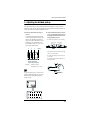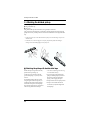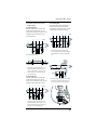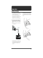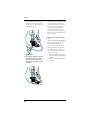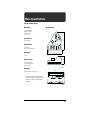
1
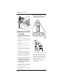
Owner’s Manual
Thank you for purchasing the Roland GK-2B divided pickup.
Before using this unit, carefully read the sections entitled:
USING THE UNIT SAFELY (Page 2–3)
IMPORTANT NOTES (Page 4)
These sections provide important information concerning the proper
operation of the unit.
Additionally, in order to feel assured that you have gained a good grasp of
every feature provided by your new unit, Owner’s manual should be read in
its entirety. The manual should be saved and kept on hand as a convenient
reference.
Copyright © 2002 ROLAND CORPORATION
All rights reserved. No part of this publication may be reproduced in any form
without the written permission of ROLAND CORPORATION.
USING THE UNIT SAFELY
The
symbol alerts the user to important instructions
or warnings.The specific meaning of the symbol is
determined by the design contained within the
triangle. In the case of the symbol at left, it is used for
general cautions, warnings, or alerts to danger.
Used for instructions intended to alert
the user to the risk of death or severe
injury should the unit be used
improperly.
Used for instructions intended to alert
the user to the risk of injury or material
damage should the unit be used
improperly.
The
symbol alerts the user to items that must never
be carried out (are forbidden). The specific thing that
must not be done is indicated by the design contained
within the circle. In the case of the symbol at left, it
means that the unit must never be disassembled.
* Material damage refers to damage or
other adverse effects caused with
respect to the home and all its
furnishings, as well to domestic
animals or pets.
The ● symbol alerts the user to things that must be
carried out. The specific thing that must be done is
indicated by the design contained within the circle. In
the case of the symbol at left, it means that the powercord plug must be unplugged from the outlet.
001
007
• Before using this unit, make sure to
read the instructions below, and the
Owner’s Manual.
• Make sure you always have the unit
placed so it is level and sure to remain
stable. Never place it on stands that
could wobble, or on inclined surfaces.
..................................................................................................
002a
• Do not open or perform any internal
modifications on the unit.
..................................................................................................
003
• Do not attempt to repair the unit, or
replace parts within it (except when
this manual provides specific instructions directing you to do so). Refer all
servicing to your retailer, the nearest
Roland Service Center, or an authorized Roland distributor, as listed on
the “Information” page.
..................................................................................................
004
• Never use or store the unit in places
that are:
• Subject to temperature extremes
(e.g., direct sunlight in an enclosed
vehicle, near a heating duct, on top
of heat-generating equipment); or
are
• Damp (e.g., baths, washrooms, on
wet floors); or are
• Humid; or are
• Exposed to rain; or are
• Dusty; or are
• Subject to high levels of vibration.
..................................................................................................
2
..................................................................................................
011
• Do not allow any objects (e.g.,
flammable material, coins, pins); or
liquids of any kind (water, soft drinks,
etc.) to penetrate the unit.
..................................................................................................
012d
• Immediately turn the power off, and
request servicing by your retailer, the
nearest Roland Service Center, or an
authorized Roland distributor, as listed
on the “Information” page when:
• Objects have fallen into, or liquid
has been spilled onto the unit; or
• The unit has been exposed to rain
(or otherwise has become wet); or
• The unit does not appear to operate
normally or exhibits a marked
change in performance.
..................................................................................................
013
• In households with small children, an
adult should provide supervision until
the child is capable of following all the
rules essential for the safe operation of
the unit.
..................................................................................................
014
• Protect the unit from strong impact.
(Do not drop it!)
..................................................................................................
104
• Try to prevent cords and cables from
becoming entangled. Also, all cords
and cables should be placed so they
are out of the reach of children.
..................................................................................................
106
• Never climb on top of, nor place heavy
objects on the unit.
..................................................................................................
108c
• Disconnect all cords coming from
external devices before moving the
unit.
..................................................................................................
118
• Should you remove the parts of installation, make sure to put them in a safe
place out of children’s reach, so there
is no chance of them being swallowed
accidentally.
..................................................................................................
For EU Countries
This product complies with the requirements of European Directives EMC 89/336/EEC and LVD 73/23/EEC.
3
IMPORTANT NOTES
291a
In addition to the items listed under “USING THE UNIT SAFELY” on page 2–3, please read and
observe the following:
Power Supply
Maintenance
307
401a
• Before connecting this unit to other devices,
turn off the power to all units. This will help
prevent malfunctions and/or damage to
speakers or other devices.
• For everyday cleaning wipe the unit with a
soft, dry cloth or one that has been slightly
dampened with water. To remove stubborn
dirt, use a cloth impregnated with a mild, nonabrasive detergent. Afterwards, be sure to
wipe the unit thoroughly with a soft, dry cloth.
Placement
351
• Using the unit near power amplifiers (or
other equipment containing large power
transformers) may induce hum. To alleviate
the problem, change the orientation of this
unit; or move it farther away from the source
of interference.
352b
• Noise may be produced if wireless communications devices, such as cell phones, are
operated in the vicinity of this unit. Such noise
could occur when receiving or initiating a call,
or while conversing. Should you experience
such problems, you should relocate such
wireless devices so they are at a greater
distance from this unit, or switch them off.
354a
• Do not expose the unit to direct sunlight,
place it near devices that radiate heat, leave it
inside an enclosed vehicle, or otherwise
subject it to temperature extremes. Excessive
heat can deform or discolor the unit.
355
• To avoid possible breakdown, do not use the
unit in a wet area, such as an area exposed to
rain or other moisture.
402
• Never use benzine, thinners, alcohol or
solvents of any kind, to avoid the possibility
of discoloration and/or deformation.
Additional Precautions
553
• Use a reasonable amount of care when using
the unit’s buttons, sliders, or other controls;
and when using its jacks and connectors.
Rough handling can lead to malfunctions.
556
• When connecting / disconnecting all cables,
grasp the connector itself—never pull on the
cable. This way you will avoid causing shorts,
or damage to the cable’s internal elements.
558b
• To avoid disturbing your neighbors, try to
keep the unit’s volume at reasonable levels
(especially when it is late at night).
559a
• When you need to transport the unit, package
it in the box (including padding) that it came
in, if possible. Otherwise, you will need to use
equivalent packaging materials.
928
* When turning the bass with GK-2B upsidedown, get a bunch of newspapers or
magazines, and place them under the four
corners or at both ends to prevent damage to
the buttons and controls. Also, you should try
to orient the unit so no buttons or controls get
damaged.
929
* When turning the bass with GK-2B upsidedown, handle with care to avoid dropping it,
or allowing it to fall or tip over.
4
CONTENTS
USING THE UNIT SAFELY ...................2
IMPORTANT NOTES ............................4
Main Features .......................................5
About the GK-2B’s warranty .............. 5
Names of Things and What They Do ........6
Attaching the GK-2B to Your Bass.....8
Cautions for installation ...................... 8
Installation procedure.............................8
Attachment examples .............................9
1. Adjusting the divided pickup ...... 11
2. Attaching the divided pickup....... 12
Attaching the pickup
with double-sided tape .........................12
Attaching the pickup with screws ......16
3. Attaching the controller................. 17
Attaching the controller
with double-sided tape or velcro ........17
Attaching the controller
with screws.............................................18
Operation ............................................19
Main Features
The GK-2B is a divided pickup designed
especially for bass. You can attach it to a
conventional bass and play the GK-compatible
device for bass from your instrument.
● Since the divided pickup contains six small
pickups, it can support basses with up to six
strings.
● The divided pickup allows you to make
adjustments for optimal performance with
basses of the distance between each string of
16 mm–19 mm.
● Tape and spacers for attaching the controller
are included, making it easy to attach the GK2B securely to your bass.
About the GK-2B’s
warranty
Roland guarantees the GK-2B (and all included
parts) to be free of defects in materials and
workmanship.
Contact your retailer or nearest Roland Service
Center if repairs become necessary.
Roland cannot be responsible for any damage
caused to your bass or the GK-2B as a result of
your attempt to install or remove the GK-2B.
If you are not confident with your ability to
properly install the Pickup or Controller unit
(especially where drilling is involved), please
contact your Roland retailer or nearest Roland
Service Center.
Getting connected............................... 19
Main Specifications............................21
5
Names of Things and What They Do
fig.01
(1) Divided Pickup
(4) Normal Pickup Input Jack
(3) Power Indicator
(5) GK Connector
(2) GK Volume
Center Marker
(8) S2 Switch
(7) S1 Switch
Pickup
(6) Select Switch
Controller
(1) Divided pickup
(4) Normal pickup input jack
This is a pickup that senses the vibration of the
bass strings. Attach it by the bridge of your
bass.
Use this jack to input the signal of the normal
pickup of your bass into the GK-2B. Use the
normal bass cable (included) to make this
connection.
(2) GK volume
The function of the GK volume will differ
depending on the GK-compatible device it is
used with. Please refer to the owner's manual
for your GK-compatible device.
(3) Power indicator
This indicator will light when the GK-2B is
connected to a GK-compatible device via a GK
cable.
6
(5) GK connector
Use this connector to connect the GK-2B to a
GK-compatible device.
Names of Things and What They Do
(6) Select switch
This switch selects the sound that is output
from the connected GK-compatible device.
In the “BASS” position, the normal pickup
sound of the bass will be output. In the “MIX”
position, the normal pickup sound of the bass
and the sound of the GK-compatible device will
be mixed and output. In the “GK” position, the
sound of the GK-compatible device will be
output. For details, refer to the owner’s manual
for your GK-compatible device.
(7) S1 switch
(8) S2 switch
The functions of the S1/S2 switches differ
depending on the GK-compatible device you
are using. For details, refer to the owner’s
manual for your GK-compatible device.
7
Attaching the GK-2B to Your Bass
To use the GK-2B, you need to install it onto a conventional electric bass.
It is not difficult to install the GK-2B, but please read the following items carefully before you begin,
since there are several things that you should be aware of regarding how to attach the divided pickup
and controller.
Cautions for installation
● Do not use the GK-2B on a bass that has an
unconventional string configuration, a bass
with strings that have no steel core (e.g.,
nylon strings), or on a guitar. It will not
function correctly.
● Adjustments to the neck of your bass, the
string height, and intonation adjustments
must be completed before attaching the
GK-2B.
● Before you actually install the divided
pickup and controller, place them against
your bass to verify that there will be no
problems with installation.
● We recommend that you use double-sided
tape (not screws) to attach the controller first.
Then after you have played your instrument
to verify that there are no problems, use
screws to attach it permanently.
● If the GK-2B is attached only with doublesided tape or velcro fastener, it may be
dislodged by being jarred while you
perform, or due to the tape loosing its
stickiness over time. Also, depending on the
finish (e.g., lacquer) of your instrument, and
the condition of the finished surface (cracks,
peeling), some of the finish may also peel off
when the tape comes off. Please use the
double-sided tape for temporarily fastening
the GK-2B while deciding on its permanent
location, and use the velcro fastener if you
will be frequently attaching and detaching
the controller.
● Depending on the type of your bass, it may
be impossible to install the divided pickup
because the space between the bridge and
pickup is too narrow. In this case, it may be
possible to install the GK-2B by modifying
your bass (i.e., moving the pickup). Please
consult your dealer.
8
■ Installation procedure
1. Carefully read this manual, and decide the
approximate locations in which you’re
going to place the divided pickup and
controller, and how you’re going to route
the cable.
2. Adjust the divided pickup as appropriate
for your bass.
3. Attach the divided pickup to your bass.
4. Attach the controller to your bass.
5. Connect the GK-2B to your GK-compatible
device.
6. On the GK-compatible device, adjust the
sensitivity of the pickup.
* In order to play a GK-compatible device using
the GK-2B, you must adjust the divided pickup
to match the distance between each string, adjust
the height of the divided pickup, and adjust the
sensitivity on the GK-compatible device. These
adjustments are extremely important if you hope
to take full advantage of the performance of the
GK-compatible device. For the adjustment
procedure, refer to the manual of your GKcompatible device after you have finished reading
this manual.
Attaching the GK-2B to Your Bass
■ Attachment examples
fig.40_e
example 1
example 2
example 3
9
Attaching the GK-2B to Your Bass
Make sure that you have all of the following parts required for installation.
fig.02_e
Tapping Flat 3 x 16 mm
Pickup Cushion
x 1 (for installing the Controller)
x2
(for installing the Divided Pickup)
Tapping Pan 3 x 20 mm
x2
(for installing the Divided Pickup)
Pickup Spacer A
Spring
x 10
(for installing the Divided Pickup)
x2
(for installing the Divided Pickup)
Controller Spacer
Pickup Spacer B
x 3 (for installing the Controller)
x 10
(for installing the Divided Pickup)
Double-sided Tape A
x 3 (for installing the Controller)
Velcro Fastener
x 1 (for installing the Controller)
Double-sided Tape B
x4
(for installing the Divided Pickup)
Double-sided Tape
Cable Fook
x 2 (for installing the Controller)
x2
Normal Bass Cable
Double-sided Tape
(easily peeled)
x2
(for installing the Divided Pickup)
10
x1
Screwdriver
x1
Clearance Gauge
x1
Attaching the GK-2B to Your Bass
1. Adjusting the divided pickup
In the case of basses, the distance between each string differs between instruments, so you will need to
adjust the divided pickup according to the distance between each string of your bass. Unless this
adjustment is made accurately, the GK-compatible device will not function at its full potential, or may
not operate correctly. Please make this adjustment with care.
1. Measure the distance between strings on
your bass.
To determine the distance between each string,
you can measure the distance between string 1
and string 4 (or depending on the number of
strings, 5 or 6) at the location in which to install
the pickup (p.13–14), and divide by one less
than the number of strings (i.e., in the case of a
four-string bass, divide by three).
2. Use the included screwdriver to loosen the
screws, move the markers to the position of
the appropriate the distance between each
string, and tighten the screws.
* Be careful not to tighten the screws excessively.
fig.04_e
2nd string marker
loose tight
5th string marker
loose tight
fig.03_e
19 18 17 16 mm 16 17 18 19 mm
4
3
2
1 String
Position
* This adjustment made so that both left and right
sides are at the same position.
center
center
Measure the distance
between these two strings.
Example:
* Be careful when moving the markers; do not use
excessive force.
Be especially careful with those at both sides of
the bridge and head.
fig.05
a distance of 57 mm
57 divided by (4-1) = 19 mm
A gauge with pitches of 16, 17, 18, and 19 mm is
printed on the GK-2B package, and you can also
determine the spacing by placing this gauge
against your bass.
fig.52
11
Attaching the GK-2B to Your Bass
2. Attaching the divided pickup
The divided pickup can be attached in one of two ways:
● Using double-sided tape
● Using screws
Using double-sided tape is the easier method, and is generally recommended.
Using screws has the advantage that you will be able to adjust the distance between the strings and
pickup when necessary, but the procedure is somewhat more difficult than when using double-sided
tape.
* Do not apply excessive force to the cable that connects the pickup to the controller. Doing so may sever the
conductors inside.
* Do not bend, twist, or otherwise apply force to the pickup. Be particularly careful when attaching or
removing it. Do not intentionally apply force to the pickup cover.
fig.06
■ Attaching the pickup with double-sided tape
Double-sided tape of a type that can be easily
peeled off is also provided (p. 10).
* Please observe the following points when using
the reusable double-sided tape.
Use this tape if you will want to adjust the
position of the pickup, or if you may want to
remove it.
• If you use this tape to attach the divided
pickup, the divided pickup may fall off at a
later time due to physical shock during
playing, or due to ageing of the tape.
The installation method is the same as when
using the regular double-sided tape, but you
should peel off the regular double-sided tape
from the side of the spacer or divided pickup
that contacts the body of the bass, and replace it
with the easily peeled double-sided tape.
12
• This tape will not stick to the pickup cushion.
• This tape is 0.1 mm thick. Take this into
account when you adjust the height of the
divided pickup.
Attaching the GK-2B to Your Bass
1. You decide on the location in which to
install the pickup.
For a four-string bass:
Attach the divided pickup so that the center
marker is between strings 2 and 3, the 2nd
string marker is directly below string 1, and the
5th string marker is directly below string 4.
For a six-string bass:
Attach the divided pickup so that the center
marker is between strings 3 and 4, the 2nd
string marker is directly below string 2, and the
5th string marker is directly below string 5.
fig.09_e
6
5
4
3
2
1 String
(Viewed from above)
fig.07a_e
4
3
2
1
String
* The divided pickup must be installed in the
correct orientation. Make sure that the cable from
the divided pickup is extending from the bridge
side.
(Viewed from the neck)
fig.07b_e
fig.10_e
1
2
3
2nd string marker
4
5th string marker
* Depending on the GK-compatible device, it is
possible to install the pickup so that the center
marker is between strings 1 and 2, or between
strings 3 and 4. Refer to the manual for your
GK-compatible device.
For a five-string bass:
Attach the divided pickup so that the center
marker is between strings 2 and 3, the 2nd
string marker is directly below string 1, and the
5th string marker is directly below string 4.
Bridge
* Route the pickup cable so that it can be smoothly
connected to the controller, and will not get in
the way of operating the controls of your bass.
fig.11
fig.08_e
5
4
3
2
1
String
* Depending on the GK-compatible device, it is
possible to install the pickup so that the center
marker is between strings 3 and 4. Refer to the
manual for your GK-compatible device.
13
Attaching the GK-2B to Your Bass
* Install the divided pickup as close to the bridge as
possible. Regardless of the type of bass, do not
install the pickup more than 50 mm away from
the bridge.
fig.41
fig.12_e
maximum 50 mm
When you have decided on the location in
which to install the pickup, use pencil or
tape to mark that location.
2. Make sure that the neck tension and string
height are optimally adjusted, and then
tune each string.
If your bass is not set up optimally, be sure
to adjust it to the optimal state before you
tune.
* If you are attaching the pickup to a bass with a
curved surface (arched top), place a pickup
cushion beneath the pickup spacer.
fig.13_e
3. Adjust the height of the pickup.
Insert pickup spacers below the divided
pickup until you reach the necessary height.
(Do not yet peel off the protective backing.)
There are two types of pickup spacer, A
(thick) and B (thin), and these can be
combined as necessary.
Adjust the pickup height so that there is
approximately 1.5 mm of space between the
string and pickup when you press the
highest fret of each string.
Pickup Spacer
Pickup Cushion
fig.14
1.5 mm
Using the clearance gauge
The included clearance gauge is
approximately 1.5 mm thick. Insert it
between the strings and the divided pickup
as shown below to check and adjust the
spacing.
14
* The pickup spacers and pickup cushions are
attached with double-sided tape. Peeling off the
backing sheet will reduce the thickness by
approximately 0.1 mm. If you are using
numerous spacers or cushions, you will need to
increase the height to compensate for this
reduction in thickness.
* If the distance between the string and pickup
when the highest fret is pressed differs
significantly between string 1 and the lowest
string, cut a spacer in half or a third, and add it
underneath the lower end of the pickup so that
the gap is approximately the same for both sides.
Attaching the GK-2B to Your Bass
4. Loosen and remove the strings.
fig.16
5. Remove the protective backing from the
double-sided tape of the pickup cushions,
pickup spacers, and divided pickup, and
affix them to your bass.
6. Reinstall the strings, tune your bass, and
then check the height of the divided pickup
once again. Then attach the cable hook near
the bridge, and fasten the pickup cable in
the hook so that it does not lift up or touch
the strings.
fig.15_e
(4) After you have taken off the pickup,
completely remove the double-sided
tape from the bottom of the pickup. It
can be removed cleanly by rolling it
with your finger as shown below.
fig.17
Cable Fook
* At this point, we recommend that you
temporarily connect your GK-compatible device,
and check the level of each string. If there are
significant differences between the levels of the
strings, make fine adjustments to the position
and height of the pickup so that the levels are as
consistent as possible.
7. If the pickup height was not appropriate,
use the following procedure to correct it.
(1) Carefully examine the current state. If
the pickup is too low, decide how many
spacers you need to add. If it is too
high, decide how many spacers you
need to remove.
(2) Loosen and remove the strings.
(3) Pry off only the divided pickup from
the bass.
* If you bend or twist the divided pickup, the
internal circuitry could get damaged. Please use
care in removing it.
Insert a thin object such as a table knife below the
pickup, starting at the lowest string, and gently,
little by little, pry it off.
(5) Adjust the height. When adding a
spacer, remove the double-sided tape
that remains on the upper surface of the
spacer already affixed to your bass, and
attach the additional spacer on top of it.
When removing a spacer, you should
also remove any double-sided tape that
remains on the top surface after peeling
off the unneeded spacer.
(6) On the bottom surface of the pickup,
attach two new strips of the included
double-sided tape B.
(7) Attach the pickup on top of the
spacer(s) you affixed to your bass.
(8) Reinstall the strings, tune your bass,
and check the pickup height.
* After this procedure, the next step is to adjust the
pickup sensitivity on your GK-compatible device.
However, in some cases, you may find that the
level meter of the GK-compatible device is
already stuck at its maximum level. Should this
be the case, you may be able to solve the problem
by increasing the space between the strings and
pickup. Perform steps (1) through (8) to slightly
lower the height of the pickup.
15
Attaching the GK-2B to Your Bass
■ Attaching the pickup
with screws
4. As shown below, insert the springs
between the pilot holes and pickup, and
fasten the screws.
The procedure for determining the location and
height of the divided pickup is exactly the same
as when using double-sided tape to fasten the
GK-2B. Please carefully read “Attaching the
pickup with double-sided tape” before you
continue.
fig.18
* In order to install the pickup with screws, there
must at least 15.5 mm between the body and the
strings. If you are attaching the pickup to a bass
on which there is less than 15.5 mm of clearance
between the body and the strings, cut the springs
to an appropriate length.
1. Decide where you’re going to install the
pickup. When you have decided on the
location, mark the body of your bass to
indicate the locations of the holes at each
end of the pickup.
2. Loosen and remove the strings.
3. Drill pilot holes at the marked locations.
* If the pilot holes are not located accurately, the
pickup will not be positioned correctly. Be very
careful when drilling the pilot holes.
* A diameter of approximately 2 mm is appropriate
for the pilot holes.
* If the body of your bass is made of a hard
material, make the pilot holes slightly larger than
2 mm.
16
5. Reinstall the strings, and tune your bass.
6. Adjust the height of the pickup.
* Tighten or loosen the screws so that there is
approximately 1.5 mm of clearance between the
string and pickup when the highest fret is
pressed. Use the included clearance gauge (1.5
mm thick) to adjust or check the height.
* After this procedure, the next step is to adjust the
pickup sensitivity on your GK-compatible device.
However, in some cases, you may find that the
level meter of the GK-compatible device is
already stuck at its maximum level. Should this
be the case, you may be able to solve the problem
by increasing the space between the strings and
pickup. Perform step (6) to slightly lower the
height of the pickup.
Attaching the GK-2B to Your Bass
3. Attaching the controller
There are two ways to install the controller:
● Using double-sided tape or velcro
● Using screws
Using double-sided tape or velcro to install the controller is the easier method, but the controller may
come off if your bass is jarred during performance or as the tape ages. We recommend that you
consider these methods as temporary, and in general use screws to attach the controller.
■ Attaching the controller
with double-sided tape
or velcro
2. When you have decided where to install
the controller, wipe off any moisture, oil, or
dust from that location.
If you do not want to make holes in the body of
your bass, use double-sided tape or velcro to
attach the controller.
However, with this method, the controller may
come off if your bass is jarred during
performance or as the tape ages.
Also, depending on how decals are affixed, the
condition of the finished surface (cracks,
peeling), or how your bass is finished, decals or
finish may also come off of your instrument
when the tape comes off.
Use the included velcro fastener if you will be
frequently removing and re-attaching the
controller.
3. Affix double-sided tape or velcro to the
bottom of the controller.
fig.42
MADE
IN
GK-2B
JAPAN
1. Place the controller on the surface of your
bass, and decide where you’re going to
install it. At this time, keep in mind the
following points.
* Is the controller where it will not interfere with
your playing?
* Is the controller in a position where it can be
operated easily?
* Will the controller interfere with the divided
pickup?
* Is strain being placed on the normal pickup input
jack, the divided pickup, or the GK connector
cable?
* Do the plugs inserted in the GK connector or
normal pickup input jack protrude beyond the
bass? If they protrude, strain may be placed on
the GK connector or normal pickup input jack
when the bass is set down, damaging them.
4. Attach the controller to your bass.
* If you are attaching the controller to a bass with a
rounded body (e.g., an arched top), there may be
gaps between the controller and the bass, making
it difficult to attach the controller. In this case,
affix the included controller spacers to places on
the body where such gaps appear.
Use a knife or scissors to cut the body spacer to
an appropriate shape.
17
Attaching the GK-2B to Your Bass
fig.43_e
3. Affix double-sided tape to the bottom of the
controller, and fasten it using the included
screws (flat headed tapping screws).
fig.30
MADE
IN
Controller Spacer
GK-2B
JAPAN
■ Attaching the controller
with screws
1. Place the controller on the surface of your
bass, and decide where you’re going to
attach it.
At this time, keep in mind the following points.
fig.31
* Is the controller where it will not interfere with
your playing?
* Is the controller in a position where it can be
operated easily?
* Will the controller interfere with the divided
pickup?
* Is strain being placed on the normal pickup input
jack, the divided pickup, or the GK connector
cable?
* Do the plugs inserted in the GK connector or
normal pickup input jack protrude beyond the
bass? If they protrude, strain may be placed on
the GK connector or normal pickup input jack
when the bass is set down, damaging them.
2. When you have decided where to attach the
controller, place the controller on that
location, and from above, drill pilot holes
into the body of your bass through the
holes in the controller.
* Before you drill pilot holes, check once again to
make sure that there are no problems with how
the divided pickup is installed.
* A diameter of approximately 2 mm is appropriate
for the pilot holes.
18
Put the screw (flat-head) through this hole.
* If you are attaching the controller to a bass with a
rounded body (e.g., an arched top), there may be
gaps between the controller and the bass, making
it difficult to attach the controller. In this case,
affix the included controller spacers to places on
the body where such gaps appear.
Use a knife or scissors to cut the body spacer to
an appropriate shape.
Operation
Getting connected
* To prevent malfunction, and/or damage to
speakers and other gear, make sure to turn down
the volume on all your devices, then turn off their
power before you hook anything up.
* Once you’re hooked up correctly, follow the
procedure below to turn on the power. If you fail
to follow this procedure, the system may
malfunction, or your speakers may be damaged.
* The GK cable includes a locking mechanism, so
do not pull it with excessive force. Release the
lock and disconnect the cable. Press the lock with
your thumb and slide the plug out to disconnect
it easily.
fig.33
1. Make sure that your GK-compatible device
is turned off, and then use a GK cable to
connect the GK-2B to your GK-compatible
device.
* Connect the GK connector of the GK-2B to your
GK-compatible device.
fig.32_e
GK Cable
GK IN
GK-compatible Device
* To make connections to a GK-compatible device,
use a GK cable (GKC-3/5/10) or the special cable
included with the GK-compatible device. Never
use any other cable, since doing so may cause
malfunction.
19
Operation
* When performing, be sure to pass the GK cable
through your strap near the end pin of your bass.
If you fail to do this, excessive force applied to the
cable may damage your bass.
fig.34
* This connection is used when playing the normal
sound of your bass alone, or mixed with the
sound of the GK-compatible device, and also in
order to create a common electrical ground
(earth) for the bass and the GK-compatible
device. For this reason, you must make this
connection even if you are not using the normal
sound of your bass at all. If this connection is not
made, noise may occur.
3. Turn on the power of the GK-compatible
device.
The power indicator of the GK-2B will light.
Now you can play your bass to play the
connected GK-compatible device.
* The power indicator will not light unless the
following two conditions are met. Nor will the
power indicator light if you have connected a
GK-compatible device that is not self-powered,
such as the GKP-4 or US-20.
2. Connect the large plug of the normal bass
cable (included with the GK-2B) to the
output jack of your bass, and connect the
small plug to the normal pickup input jack
of the GK-2B.
fig.35_e
Normal Bass Cable
20
(1) The GK-compatible device and the GK2B must be correctly connected using a
GK cable.
(2) The power of the GK-compatible device
must be on.
Main Specifications
GK-2B: divided pickup
● Controls
● Dimensions
GK VOLUME knob
DOWN/S1 switch
UP/S2 switch
Select switch
fig.50
77
● Indicators
Power indicator
● Connectors
GK connector
Normal pickup input jack
● Weight
80
90 g/4 oz
34
● Accessories
Normal bass cable
Set of installation items
Owner’s manual
Unit: mm
13
2
* In the interest of product improvement,
the specifications and/or appearance of
this unit are subject to change without
prior notice.
Ø
138
128
118
GK cables: GKC-3, GKC-5, GKC-10
3.
3
fig.51
8.7
● Options
Unit: mm
21
MEMO
22
Information
When you need repair service, call your nearest Roland Service Center or authorized Roland distributor in your country as
shown below.
AFRICA
EGYPT
Al Fanny Trading Office
9, EBN Hagar A1 Askalany Street,
ARD E1 Golf, Heliopolis,
Cairo 11341, EGYPT
TEL: 20-2-417-1828
REUNION
Maison FO - YAM Marcel
25 Rue Jules Hermann,
Chaudron - BP79 97 491
Ste Clotilde Cedex,
REUNION ISLAND
TEL: (0262) 218-429
SINGAPORE
Swee Lee Company
150 Sims Drive,
SINGAPORE 387381
TEL: 846-3676
CRISTOFORI MUSIC PTE
LTD
Blk 3014, Bedok Industrial Park E,
#02-2148, SINGAPORE 489980
TEL: 243 9555
TAIWAN
PANAMA
ITALY
ISRAEL
SUPRO MUNDIAL, S.A.
Roland Italy S. p. A.
Boulevard Andrews, Albrook,
Panama City, REP. DE PANAMA
TEL: 315-0101
Viale delle Industrie 8,
20020 Arese, Milano, ITALY
TEL: (02) 937-78300
Halilit P. Greenspoon &
Sons Ltd.
PARAGUAY
NORWAY
Distribuidora De
Instrumentos Musicales
J.E. Olear y ESQ. Manduvira
Asuncion PARAGUAY
TEL: (021) 492-124
Roland Scandinavia Avd.
Kontor Norge
245 Prince Mohammad St.,
Amman 1118, JORDAN
TEL: (06) 464-1200
Easa Husain Al-Yousifi
PERU
VIDEO Broadcast S.A.
POLAND
Portinari 199 (ESQ. HALS),
San Borja, Lima 41,
REP. OF PERU
TEL: (01) 4758226
P. P. H. Brzostowicz
SOUTH AFRICA
Room 5, 9fl. No. 112 Chung Shan
N.Road Sec.2, Taipei, TAIWAN,
R.O.C.
TEL: (02) 2561 3339
UL. Gibraltarska 4.
PL-03664 Warszawa POLAND
TEL: (022) 679 44 19
That Other Music Shop
(PTY) Ltd.
THAILAND
URUGUAY
PORTUGAL
P.O.Box 32918, Braamfontein 2017
Johannesbourg, SOUTH AFRICA
TEL: (011) 403 4105
Paul Bothner (PTY) Ltd.
17 Werdmuller Centre,
Main Road, Claremont 7708
SOUTH AFRICA
P.O.BOX 23032, Claremont 7735,
SOUTH AFRICA
TEL: (021) 674 4030
ASIA
CHINA
Beijing Xinghai Musical
Instruments Co., Ltd.
6 Huangmuchang Chao Yang
District, Beijing, CHINA
TEL: (010) 6774 7491
Shanghai Xingtong Acoustics
Equipment CO.,Ltd.
5F. No.1500 Pingliang Road
New East Club Plaza, Shanghai,
CHINA
TEL: (021) 5580-0800
HONG KONG
Tom Lee Music Co., Ltd.
Service Division
22-32 Pun Shan Street, Tsuen
Wan, New Territories,
HONG KONG
TEL: 2415 0911
INDIA
Rivera Digitec (India) Pvt. Ltd.
409, Nirman Kendra Mahalaxmi
Flats Compound Off. Dr. Edwin
Moses Road, Mumbai-400011,
INDIA
TEL: (022) 498 3079
INDONESIA
Theera Music Co. , Ltd.
330 Verng NakornKasem, Soi 2,
Bangkok 10100, THAILAND
TEL: (02) 2248821
VIETNAM
ROMANIA
Av. Francisco de Miranda,
Centro Parque de Cristal, Nivel
C2 Local 20 Caracas
VENEZUELA
TEL: (212) 285-8586
Piata Libertatii 1,
RO-4200 Gheorghehi
TEL: (095) 169-5043
EUROPE
AUSTRIA
Roland Corporation
Australia Pty., Ltd.
38 Campbell Avenue
Dee Why West. NSW 2099
AUSTRALIA
TEL: (02) 9982 8266
NEW ZEALAND
Roland Corporation Ltd.
32 Shaddock Street, Mount Eden,
Auckland, NEW ZEALAND
TEL: (09) 3098 715
CENTRAL/LATIN
AMERICA
ARGENTINA
Instrumentos Musicales S.A.
Av.Santa Fe 2055
(1123) Buenos Aires
ARGENTINA
TEL: (011) 4508-2700
Rua San Jose, 780 Sala B
Parque Industrial San Jose
Cotia - Sao Paulo - SP, BRAZIL
TEL: (011) 4615 5666
COSTA RICA
JUAN Bansbach
Instrumentos Musicales
Ave.1. Calle 11, Apartado 10237,
San Jose, COSTA RICA
TEL: 258-0211
CHILE
Comercial Fancy
BENTLEY MUSIC SDN BHD
140 & 142, Jalan Bukit Bintang
55100 Kuala Lumpur,MALAYSIA
TEL: (03) 2144-3333
PHILIPPINES
G.A. Yupangco & Co. Inc.
339 Gil J. Puyat Avenue
Makati, Metro Manila 1200,
PHILIPPINES
TEL: (02) 899 9801
BELGIUM/HOLLAND/
LUXEMBOURG
Roland Benelux N. V.
Houtstraat 3, B-2260, Oevel
(Westerlo) BELGIUM
TEL: (014) 575811
DENMARK
Roland Scandinavia A/S
Nordhavnsvej 7, Postbox 880,
DK-2100 Copenhagen
DENMARK
TEL: (039)16 6200
FRANCE
4, Rue Paul Henri SPAAK,
Parc de l'Esplanade, F 77 462 St.
Thibault, Lagny Cedex FRANCE
TEL: 01 600 73 500
Roland Brasil Ltda
1461-9, Seocho-Dong,
Seocho Ku, Seoul, KOREA
TEL: (02) 3486-8855
Siemensstrasse 4, P.O. Box 74,
A-6063 RUM, AUSTRIA
TEL: (0512) 26 44 260
Roland France SA
BRAZIL
Cosmos Corporation
Roland Austria GES.M.B.H.
S.A.
Rut.: 96.919.420-1
Nataniel Cox #739, 4th Floor
Santiago - Centro, CHILE
TEL: (02) 688-9540
EL SALVADOR
OMNI MUSIC
75 Avenida Norte y Final
Alameda Juan Pablo ,
Edificio No.4010 San Salvador,
EL SALVADOR
TEL: 262-0788
MEXICO
Casa Veerkamp, s.a. de c.v.
Av. Toluca No. 323, Col. Olivar
de los Padres 01780 Mexico D.F.
MEXICO
TEL: 668-0480
FINLAND
Roland Scandinavia As,
Filial Finland
Lauttasaarentie 54 B
Fin-00201 Helsinki, FINLAND
TEL: (9) 682 4020
GERMANY
Roland Elektronische
Musikinstrumente HmbH.
FBS LINES
RUSSIA
MuTek
3-Bogatyrskaya Str. 1.k.l
107 564 Moscow, RUSSIA
TEL: (095) 169 5043
SPAIN
Roland Electronics
de España, S. A.
Calle Bolivia 239, 08020
Barcelona, SPAIN
TEL: (93) 308 1000
SWEDEN
Roland Scandinavia A/S
SWEDISH SALES OFFICE
Danvik Center 28, 2 tr.
S-131 30 Nacka SWEDEN
TEL: (08) 702 0020
SWITZERLAND
Roland (Switzerland) AG
Musitronic AG
Gerberstrasse 5, Postfach,
CH-4410 Liestal, SWITZERLAND
TEL: (061) 927-8383
UKRAINE
TIC-TAC
Mira Str. 19/108
P.O. Box 180
295400 Munkachevo, UKRAINE
TEL: (03131) 414-40
UNITED KINGDOM
Roland (U.K.) Ltd.
Atlantic Close, Swansea
Enterprise Park, SWANSEA
SA7 9FJ,
UNITED KINGDOM
TEL: (01792) 700139
Oststrasse 96, 22844 Norderstedt,
GERMANY
TEL: (040) 52 60090
MIDDLE EAST
GREECE
BAHRAIN
STOLLAS S.A.
Music Sound Light
155, New National Road
Patras 26442, GREECE
TEL: (061) 43-5400
HUNGARY
Intermusica Ltd.
Warehouse Area ‘DEPO’ Pf.83
H-2046 Torokbalint, HUNGARY
TEL: (23) 511011
IRELAND
Roland Ireland
Audio House, Belmont Court,
Donnybrook, Dublin 4.
Republic of IRELAND
TEL: (01) 2603501
LEBANON
A. Chahine & Fils
Gerge Zeidan St., Chahine Bldg.,
Achrafieh, P.O.Box: 16-5857
Beirut, LEBANON
TEL: (01) 20-1441
Al Emadi Co. (Badie Studio
& Stores)
Musicland Digital C.A.
AUSTRALIA
Abdullah Salem Street,
Safat, KUWAIT
TEL: 243-6399
QATAR
VENEZUELA
AUSTRALIA/
NEW ZEALAND
KUWAIT
Cais Das Pedras, 8/9-1 Dto
4050-465 PORTO
PORTUGAL
TEL: (022) 608 00 60
138 Tran Quang Khai St.,
District 1
Ho Chi Minh City
VIETNAM
TEL: (08) 844-4068
PT Citra IntiRama
MALAYSIA
Francisco Acuna de Figueroa 1771
C.P.: 11.800
Montevideo, URUGUAY
TEL: (02) 924-2335
Tecnologias Musica e Audio,
Roland Portugal, S.A.
Saigon Music
J1. Cideng Timur No. 15J-150
Jakarta Pusat
INDONESIA
TEL: (021) 6324170
KOREA
Todo Musica S.A.
JORDAN
AMMAN Trading Agency
Lilleakerveien 2 Postboks 95
Lilleaker N-0216 Oslo
NORWAY
TEL: 273 0074
ROLAND TAIWAN
ENTERPRISE CO., LTD.
11 Melle St., Braamfontein,
Johannesbourg, SOUTH AFRICA
8 Retzif Ha'aliya Hashnya St.
Tel-Aviv-Yafo ISRAEL
TEL: (03) 6823666
Moon Stores
No.16, Bab Al Bahrain Avenue,
P.O.Box 247, Manama 304,
State of BAHRAIN
TEL: 211 005
CYPRUS
Radex Sound Equipment Ltd.
17, Diagorou Street, Nicosia,
CYPRUS
TEL: (02) 66-9426
P.O. Box 62,
Doha, QATAR
TEL: 4423-554
SAUDI ARABIA
aDawliah Universal
Electronics APL
Corniche Road, Aldossary Bldg.,
1st Floor, Alkhobar,
SAUDI ARABIA
P.O.Box 2154, Alkhobar 31952
SAUDI ARABIA
TEL: (03) 898 2081
SYRIA
Technical Light & Sound
Center
Bldg. No. 47,
Khaled Ebn Al Walid St.
Damascus, SYRIA
TEL: (011) 221-1230
TURKEY
Barkat muzik aletleri ithalat
ve ihracat Ltd Sti
Siraselviler Caddesi Siraselviler
Pasaji No:74/20
Taksim - Istanbul, TURKEY
TEL: (0212) 2499324
U.A.E.
Zak Electronics & Musical
Instruments Co. L.L.C.
Zabeel Road, Al Sherooq Bldg.,
No. 14, Grand Floor, Dubai, U.A.E.
TEL: (04) 3360715
NORTH AMERICA
CANADA
Roland Canada Music Ltd.
(Head Office)
5480 Parkwood Way Richmond
B. C., V6V 2M4 CANADA
TEL: (0604) 270 6626
Roland Canada Music Ltd.
(Toronto Office)
Unit 2, 109 Woodbine Downs
Blvd, Etobicoke, ON
M9W 6Y1 CANADA
TEL: (0416) 213 9707
U. S. A.
Roland Corporation U.S.
5100 S. Eastern Avenue
Los Angeles, CA 90040-2938,
U. S. A.
TEL: (323) 890 3700
IRAN
MOCO, INC.
No.41 Nike St., Dr.Shariyati Ave.,
Roberoye Cerahe Mirdamad
Tehran, IRAN
TEL: (021) 285-4169
As of January 1, 2002 (Roland)