1
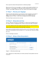
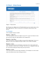
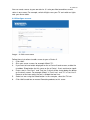
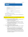
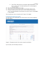
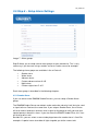
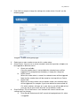
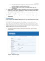
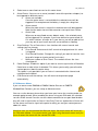
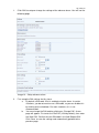
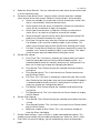
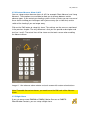
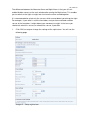
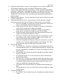
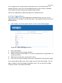
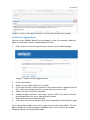
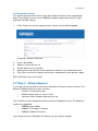
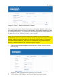
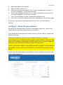
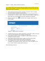
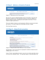
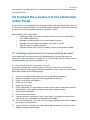
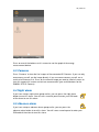
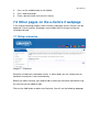
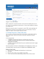
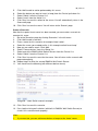
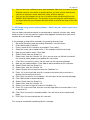
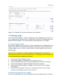
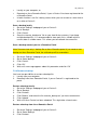
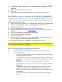
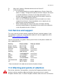
EM6505 e-Domotica e-Centre 2 Control Panel
2 | ENGLISH
EM6505 e-Domotica e-Centre 2 Control Panel
Table of contents
1.0 Introduction ...........................................................................................................4
1.1 Functions and features ......................................................................................4
1.2 Packing contents ...............................................................................................4
2.0 Installing the e-Centre 2.........................................................................................4
3.0 First installation wizard ..........................................................................................5
3.1 Step 1 – Choose your language.........................................................................6
3.2 Step 2 – Setup date and time ............................................................................6
3.3 Step 3 – Setup e-Domotica products .................................................................6
3.4 Step 4 – Setup Scenes ......................................................................................8
3.4.1 Examples ................................................................................................... 8
3.4.2 Configure a scene ...................................................................................... 9
3.4.3 Change the order of the scenes.................................................................11
3.5 Step 5 – Setup Alarm Settings.........................................................................12
3.5.1 Smoke Alarm.............................................................................................12
3.5.2 Water Alarm ..............................................................................................14
3.5.3 Absence Alarm ..........................................................................................15
3.5.4 Custom Absence Alarm A & B ...................................................................18
3.5.5 Night Alarm................................................................................................18
3.5.6 Custom Night Alarm C & D ........................................................................21
3.5.7 Setup PIN code to disarm all alarm groups ................................................21
3.6 Step 6 – Special Wizards.................................................................................21
3.6.1 Time Triggered Scene ...............................................................................22
3.6.2 Sensor Triggered Scene............................................................................23
3.6.3 Delayed off sensor.....................................................................................24
3.7 Step 7 – Setup Camera’s.................................................................................24
3.8 Step 8 – Setup Wireless Network ....................................................................26
3.9 Step 9 – Optimise e-Domotica Products ..........................................................28
3.10 Step 10 – Setup Portal connection.................................................................28
4.0 Connect the e-Centre 2 to the e-Domotica online Portal ......................................29
4.1 Creating a new account or use an existing account .........................................29
4.1.1 Create and activate a new online account..................................................29
4.1.2 Using an existing account..........................................................................30
4.2 Home page......................................................................................................30
4.3 Provide your personal information ...................................................................30
4.3.1 e-Centre status information........................................................................30
4.3.2 Change your portal password ....................................................................30
4.4 Manage contact persons .................................................................................30
4.5 Alarm reports...................................................................................................31
4.6 View Cameras .................................................................................................31
4.7 Manage recordings..........................................................................................31
4.8 Enable or disable your alarm remotely.............................................................32
3 | ENGLISH
4.9 Alarm Setup to notify contact persons and record a camera ............................32
4.9.1 Contact Persons ........................................................................................32
4.9.2 Notifications...............................................................................................32
4.9.3 Assign Camera ..........................................................................................32
4.10 Phone call configuration ................................................................................32
5.0 Using the e-Centre 2 control panel ......................................................................33
5.1 Devices ...........................................................................................................33
5.1.1 Settings window.........................................................................................34
5.1.1.1 Change backlight....................................................................................34
5.1.1.2 Change volume ......................................................................................34
5.1.1.3 Device information and network information ...........................................34
5.2 Information window..........................................................................................34
5.3 Cameras..........................................................................................................35
5.4 Night alarm ......................................................................................................35
5.5 Absence alarm ................................................................................................35
5.6 Coming Home .................................................................................................36
5.7 Messages and information bar.........................................................................36
5.8 Scenes ............................................................................................................36
5.9 Time and date bar ...........................................................................................36
6.0 Control your e-Centre locally and remotely on a smart phone or tablet ................36
6.1 Control the e-Centre locally .............................................................................36
6.2 Control the e-Centre remotely..........................................................................37
6.3 Create a shortcut icon on a Android phone or tablet ........................................37
6.4 Create a shortcut icon on a iPhone or iPad......................................................37
7.0 Other pages on the e-Centre 2 webpage .............................................................38
7.1 Setup scenarios...............................................................................................38
7.1.1 Example using events – Setup an hotel switch ..........................................39
7.1.2 Example using events and conditions – Switch on year, month, week, hour,
day or minute .....................................................................................................41
7.2 Settings page ..................................................................................................42
7.2.1 Portal firmware update...............................................................................42
7.2.2 Create a backup from your settings ...........................................................42
7.2.3 Restore a backup ......................................................................................43
8.0 Reset your e-Centre 2 to factory defaults.............................................................44
9.0 Frequently Asked Questions................................................................................44
10.0 Service and support...........................................................................................45
11.0 Warning and points of attention .........................................................................45
12.0 Warranty conditions...........................................................................................46
13.0 Declaration of Conformity ..................................................................................47
4 | ENGLISH
1.0 Introduction
Congratulations with the purchase of this high-quality e-Domotica product! This
product has undergone extensive testing by e-Domotica’s technical experts. Should
you experience any problems with this product, you are covered by a five-year eDomotica warranty. Please keep this manual and the receipt in a safe place.
Do not forget to register your product on the online portal for more functions and
product updates.
1.1 Functions and features
The EM6505 e-Domotica e-Centre 2 Control Panel is a multifunctional device which
can control certified Z-wave devices and surveillance IP camera’s all at once. You can
think of the EM6511 Remote Control, EM6550 On/Of Switch, EM6551 Dimmer,
EM6581 Motion Sensor the EM6590 smoke detector and many more. You can also
connect several Eminent IP Camera models, like the EM6561 Indoor PTZ IP Camera
and EM6564 Outdoor IP Camera.
By using products from the e-Domotica family, you can control your lighting in a simple
manner, and let the e-Centre 2 function as a part of your security system.
1.2 Packing contents
The following parts need to be present in the packing:
•
EM6505 e-Domotica e-Centre 2 Control Panel
•
Mounting bracket (also functions as a foot)
•
Power supply (12V DC 2A with EU and UK plug)
•
Quick install guide
•
Network cable
•
Screws and plugs
2.0 Installing the e-Centre 2
The basic steps to install your e-Centre are described in the quick install guide and in
this chapter. The steps are repeated in this chapter.
Hint: Make it easier for yourself and place all the e-Domotica products you have
bought on a table to check every product. This is also easier to connect all products to
each other before installing/using them on the place you want to use the products.
1.
2.
3.
Connect the network cable to the e-Centre 2 and to your network (modem or
router)
Plug in the power adapter to the e-Centre 2 and to the mains.
The e-Centre 2 will start automatically. Once the e-Centre 2 is finished you will
see a few icons on the screen.
5 | ENGLISH
4.
5.
6.
Start-up your computer.
Open a web browser like Firefox, Chrome or Internet Explorer.
Empty the address bar and enter http://ecentre/ to open the local webpage of the
e-Centre 2.
If you cannot open this location, use the IP-address of the e-Centre to open the
webpage. You can find the IP-address on the e-Centre by pressing the button
Devices, then press Settings. For example: If the IP-address is 192.168.1.30, you
can enter http://192.168.1.30 in the address bar. You will see the following page.
Image 1 – Login page of the e-Centre
7.
8.
Enter the default PIN code 1234 to continue.
The local webpage of the e-Centre 2 has a built-in wizard to help you to install
several types of products. Follow the instructions on the page to continue. The
installation wizard will be explained in the next chapter.
Note! During the installation procedure you need use a wired connection between your
network and the e-Centre 2. Once the installation wizard is done, you can disconnect
the network cable and use the e-Centre 2 wirelessly, if you wish.
3.0 First installation wizard
Now that you have opened the local webpage, as described in chapter 2.0, you can
start the first installation wizard to guide you in the process of installing your e-Centre
to your own desire.
Note! For advanced users only: If you do not want to use the Wizard, click on ‘Exit
Wizard’ at the bottom of the page.
6 | ENGLISH
Each step of the wizard will be explained in the following chapters.
Because the e-Centre has many options, you might need to go back and forth in the
Wizard, this is not a problem. All information will be saved when you click ‘Next’ or
‘Previous’ on the page, except when you see a special ‘Save’ button on the page.
3.1 Step 1 – Choose your language
Choose your desired language. If you change to a certain language a message will
appear and the language is changed of all contents of the webpage. Both the
webpage and the e-Centre 2 screen will be changed to the desired language.
Click ‘Next Step‘ to continue to the next step.
3.2 Step 2 – Setup date and time
You can select your time zone in the pull down list. Click on the ‘Set’ button to save
the setting. The time is displayed on the e-Centre 2 screen and used in the log files.
If you have selected a time zone location from the pull down list, you do not need to
setup the date and time manually. Click ‘Next Step’ to continue.
If you want to set the date and time manually, you can use the ‘Date and Time’ option.
Click on the ‘Set’ button to save the settings. This is not necessary if you have setup a
time zone.
Click on ‘Next Step’ to continue.
3.3 Step 3 – Setup e-Domotica products
Image 2 – e-Domotica products page
On this page you can add (include) to or remove (exclude) Z-wave products from the
e-Centre 2.
7 | ENGLISH
Hints:
•
The default range of the e-Centre to find Z-wave products is about 1 to 5 meters.
You might need to enable the option ‘Normal/High Power’ to include devices
used on a wide range. For example, if you have built in Z-wave devices (like the
EM6514 Wall Switch Sensor or EM6556 Mini Switch) in ceilings or walls on a
larger distance from the e-Centre.
•
To stabilise the wireless network between the Z-wave devices it is recommended
to include the mains powered products first and battery powered devices last.
230V Devices function also as a repeater, for example the EM6550 and EM6551.
•
You can even mount the 230V products in every room after inclusion to have a
greater Z-wave network to include the battery powered devices in the same
room. The benefit of doing this is that the Z-wave network knows directly where
the device is located and which neighbouring devices are in the area.
1.
2.
3.
4.
5.
6.
7.
8.
9.
Click on the ‘Include’ button.
The e-Centre 2 will now search for a Z-wave device.
Press three times within 1,5 second on the linclude button of your Z-wave device
to include it to the e-Centre 2.
Note that every Z-wave device has its own include/exclude button. Refer to the
manual of the device itself to learn were this button is located and how to use it.
If the device is recognized by the e-Centre 2, it will show the correct type.
Enter a desired name. For example if you use an EM6550 for a lamp in your
living room, you can name the device ‘Lamp’. If you want to switch a device, you
can use the name of the device, for example ‘Television’.
Select a location from the list. For example ‘Living room’.
Click on the ‘Select’ button to select a desired icon for this device. This icon will
appear as a button on the Devices screen on the e-Centre 2. In this way, you
can press this button to switch the device on or off.
Click ‘Save’ to save all settings for this device.
You will return to the ‘Setup e-Domotica Products’ page.
You can follow the above steps to include all your products. Once you are done, you
can click ‘Next’ to continue the wizard.
8 | ENGLISH
3.4 Step 4 – Setup Scenes
Image 3 – Setup scenes
Now that you have added several e-Domotica devices you can create scenes using
these added devices. Within a scene you can change the state of one or more
devices.
3.4.1 Examples
A few examples to get you started:
Example 1 – Watch TV
In this scene you can switch on the lights near your TV. If you use a dimmer as well,
you can dim the light to the right ambience (for example 30%).
Example 2 – Have Diner
In this scene you can switch on the lights near your dinner table. Again if you use a
dimmer as well, you can brighten the lights to 90% or even 100% for example.
Example 3 – All on
In this scene you can turn on all the lights in your house. This scene can be used
when setting up a smoke alarm for example. Once the alarm is triggered all lights go
on in your house to help you find your way out of your house.
Example 4 – All off
In this scene you can turn off all lights and devices. For example, this scene can be
used in the absence alarm when exiting your house.
9 | ENGLISH
You can create scenes to your own desire. It is also possible to combine several
states in one scene. For example, switch off lights near your TV and switch on lights
near your dinner table.
3.4.2 Configure a scene
Image – 4. Add a new scene
Follow these instructions to add a scene to your e-Centre 2.
1. Click ‘Add’.
2. Give your scene a name, for example ‘Watch TV’.
3. If you want to have button displayed on the e-Centre 2 touchscreen, enable the
checkbox ‘Show button for this scene on the e-Centre’. If not, continue to step 6.
4. Enter a text in ‘Text line 1’ and ‘Text line 2’ which will be shown below the button
on the touch screen. For example ‘Watch’ in Text Line 1 and ‘TV’ in Text Line 2.
Because of the icon matrix the text is divided into two lines.
5. Select an icon using the Select button. In this example, select the TV icon.
6. Click ‘Add’ to add one or more e-Domotica products to this scene.
10 | ENGLISH
7.
A new page will appear with several options.
Image 5. Add a product to a new scene
The next steps are divided into two situations, one with a selected Switch and
one with a selected Dimmer.
Note: Enable the Expert mode function if you are more experienced with Z-wave and
setting up devices. The Expert mode will not be described in this chapter.
8.
9.
Setup this page using a Switch (EM6550 for example)
a. Device: Select your desired switchable device or lamp from the first
pull down list. For example ’Lamp’.
b. Feature: You can only select Switch in this case.
c. Action: You can choose between ‘Assign To’ or ‘Invert’. ‘Assign to’
allows you to switch on or off your device. The option ‘Invert’ allows
you to change the state of the device.
d. Value: Select ‘On’ to switch the device on in this scene. Select ‘Off’ to
switch the device ‘off’ in this scene
Setup this page using a Dimmer (EM6551 for example)
a. Device: Select the desired dimmable lamp from the list. For example
’Lamp’.
b. Feature: You can choose between ‘Level’ and ‘Switch’. The ‘Level’
option allows you to set the Dimmer to a certain percentage. The
‘Switch’ option allows you to switch on or off a dimmable lamp.
c. Action: You can choose between ‘Assign To’, ‘Decrease with’ and
‘Increase with’. ‘Assign To’ allows you to switch your lamp on or off.
‘Decrease with’ allows you to level down the lamp with a certain step.
For example 10. ‘Increase with’ allows you to level up the lamp with a
certain step. For example 10.
11 | ENGLISH
d.
Value: Enter a desired value, for example a percentage between 1 and
99, or a certain step. You might need to try this first and change the
setting later again.
10. Click ‘Save’ to return to the previous page.
11. You can add several devices to this scene using the above steps 6 to 10.
12. Once you are done, you can click ‘Save’ to save all settings concerning this
scene. If you have decided to show a button on the touch screen it should appear
in a few seconds.
You can add several scenes using the same 12 steps in this chapter.
3.4.3 Change the order of the scenes
The order of the scenes displayed on the e-Centre touch screen can be changed by
your own website.
Image 6 – Changing the order of the scenes using the arrow buttons.
If you are done, click ‘Next Step’ to continue.
12 | ENGLISH
3.5 Step 5 – Setup Alarm Settings
Image 7 - Alarm groups
Step 5 allows you to setup several alarm groups at your own desire. This is only
necessary if you have are using a motion sensor or smoke sensor for example.
The following alarm groups are available in the e-Centre 2:
•
Smoke alarm
•
Water alarm
•
Absence alarm
•
Custom absence alarm A & B
•
Night alarm
•
Custom night alarm C & D
Each alarm group is described in the following chapters.
3.5.1 Smoke Alarm
If you use one or more EM6590 Smoke Sensors, you can setup a Smoke Alarm
group.
The EM6590 Smoke Sensor can detect smoke and make noise by itself, but also send
a signal to the e-Centre at the same time. If you setup a Smoke Alarm, the e-Centre
will also make a loud noise and can send a signal to the portal to notify you and your
contact persons about this alarm. If you also have the EM6575 Indoor Siren, this siren
will also go off as well.
Besides this, you can select a scene to be played once the smoke alarm is fired. For
example: A special scene to enable all lights to guide you to the nearest exit.
13 | ENGLISH
1.
Click ‘Edit’ to setup or change the settings of a smoke alarm. You will see the
following page.
Image 8 – Smoke alarm group page
2.
3.
4.
Select one or more smoke sensors for this smoke alarm.
Alarm Events: You can use a scene (created in one of the previous chapters) to
be triggered on different events.
a. Alarm not available:
Once the smoke alarm is not available the selected scene will be
triggered. For example once the battery is empty for a long time
b. Alarm armed:
When the smoke alarm is armed, the selected scene will be triggered.
Note that the smoke alarm will be armed on start-up of the e-Centre.
c. Alarm fired:
When one or more smoke sensors detect smoke, the selected scene
will be triggered. For example, if you have defined a scene called ‘All
On’ which switches all lamps on in your house, you will be able to find
your way out of your house once the sensor detects smoke.
Siren Settings: The e-Centre has a siren function with several sounds and
settings you can change.
a. Siren Sound: Select one of the 5 sounds to be played once this alarm
is triggered
14 | ENGLISH
b.
5.
6.
Siren Sound Duration: Change this setting if you want to have the siren
to go off a longer or shorter period (in minutes).
c. Maximum number of Siren Count: The number of times the siren
should go off.
Portal Settings: Enable this option if you want to send a signal to the e-Domotica
Portal once a smoke alarm is detected. This allows you to notify yourself and/or
contact persons about the smoke alarm.
This option is only possible if your e-Centre is connected to the internet and
registered on the portal.
Click ‘Save’ to save the settings. You will return to the previous page
automatically.
3.5.2 Water Alarm
If you use one or more EM6592 Flood Sensors, you can setup a Water Alarm system.
The EM6592 Flood Sensor can detect water flooding and send a signal to the eCentre. You can use the EM6592 in a basement or near a washing machine. If you
setup a Water Alarm, the e-Centre will make a loud noise, and can send a signal to
the portal to notify you and your contact persons about this alarm. If you also have the
EM6575 Indoor Siren, this siren will also go off as well.
1.
Click ‘Edit’ to setup or change the settings of a water alarm. You will see the
following page.
Image 9 – Water alarm group
15 | ENGLISH
2.
3.
4.
5.
6.
Select one or more flood sensors for this water alarm.
Alarm Events: You can use a scene (created in one of the previous chapters) to
be triggered on different events.
a. Alarm not available:
Once the water alarm is not available the selected scene will be
triggered. For example once the battery is empty for a long time.
b. Alarm armed:
When the water alarm is armed, the selected scene will be triggered.
Note that the water alarm will be armed on start-up of the e-Centre.
c. Alarm fired:
When one or more flood sensors detects water , the selected scene
will be triggered. For example, if you have defined a scene called ‘All
On’ which switches all lamps on in your house, you will be able to find
your way out of your house once the sensor detects a flooding.
Siren Settings: The e-Centre has a siren function with several sounds and
settings you can change.
d. Siren Sound: Select one of the 5 sounds to be played once this alarm
is triggered
e. Siren Sound Duration: Change this setting if you want to have the siren
to go off a longer or shorter period (in minutes).
f.
Maximum number of Siren Count: The number of times the siren
should go off.
Portal Settings: Enable this option if you want to send a signal to the e-Domotica
Portal once a water alarm is detected. This allows you to notify yourself and/or
contact persons about the water alarm.
This option is only possible if your e-Centre is connected to the internet and
registered on the portal.
Click Save to save the settings. You will return to the previous page
automatically.
3.5.3 Absence Alarm
If you use one or more EM6580 or EM6581 Motion Sensors or EM6570
Window/Door Contacts, you can setup an Absence alarm.
You can use the absence alarm when you leave your house for a certain period, for
example going to work. When enabling the alarm using your PIN code, the selected
sensors will be armed. Once the sensors detect movement or an open door/window
they will send a signal to the e-Centre. If the Entry Time has expired the e-Centre will
fire the alarm and send a signal to the portal to notify you and your contact persons
about this alarm.
Note that once you have armed the Absence alarm, the touch screen will show only
the PIN code window. You cannot control your lights using the touch screen until you
have disarmed the alarm with the correct PIN code.
16 | ENGLISH
1.
Click ‘Edit’ to setup or change the settings of the absence alarm. You will see the
following page.
Image 10 – Setup absence alarm
2.
First setup the PIN settings for this alarm.
a. By default a PIN code 1234 is enabled using the alarm. In certain
situations, you do not want to use a PIN code, so you can disable this
by clicking on the checkbox. For most situations, this is not
recommended.
b. You can change the PIN code by clicking on ‘Change PIN’. A new
page will appear. First enter the ‘Old PIN’ (1234 by default), then enter
the ‘New PIN’. Confirm the new PIN code in the field ‘Repeat PIN’.
Click ‘Save’ to save the settings and automatically go back to the
previous page.
17 | ENGLISH
3.
4.
5.
6.
7.
8.
Select the Alarm Sensors. You can select one or more alarm sensors to be used
in for this absence alarm.
Set one or more Alarm Events. You can let the e-Centre execute a selected
scene on one of the alarm events. Below a list of the events and a example
a. Alarm not available: If you want the e-Centre to execute a scene if the
alarm is not available, select the desired scene.
b. Alarm armed: Once the alarm is armed the e-Centre can execute the
scene ‘All off’ to switch off all lights, for example.
c. Alarm fired: Once the alarm is fired the e-Centre can execute the
scene ‘All on’, to switch on all lights to scare off the intruder.
d. Alarm disarmed: If you disarm the alarm (by entering the correct PIN
code) the e-Centre will execute this scene.
e. Entry time: During the entry time the e-Centre can execute this scene.
For example, use a scene to enable the lights in your hallway. This
allows you to find your way to the e-Centre when entering your house.
f.
Exit time: During the exit time the e-Centre can execute this scene. For
example, use a scene to enable the lights in your hallway. This allows
you to find your way to the door when exiting your house.
Set the time settings.
a. Entry Time: This is the time in seconds you need to enter your house
from the (front) door to the e-Centre and to disable the alarm. It is
recommended to check this carefully and to try this setting once it has
been set. If necessary change the setting to your desire.
b. Entry Sound: The e-Centre will play the selected sound on entering
your house.
c. Entry Sound Interval: This is the interval the e-Centre should use to
play the Entry Sound.
d. Exit Time: This is the time in second you need to exit your house, from
the e-Centre to the (front) door, once you have entered the PIN code. It
is recommended to check and try this setting once it has been set. If
necessary change the setting to your desire.
e. Exit Sound: The e-Centre will play the selected sound when exiting
your house.
f.
Exit Sound Interval: This is the interval the e-Centre should use to play
the Exit Sound.
Set the Siren Settings.
a. Siren Sound: The e-Centre will play the selected sound when the alarm
is fired
b. Siren Sound Duration: This is the time (in minutes) the e-Centre should
play the Siren Sound.
c. Maximum number of Siren Count: This is the maximum number of
times the Siren should play.
Set the Portal settings, if your e-Centre is (to be) connected to the portal. This
enables you to contact yourself and/or contact persons when this alarm is fired.
Click ‘Save’ to save the settings, you will automatically return to the previous
page.
18 | ENGLISH
3.5.4 Custom Absence Alarm A & B
You can setup custom absence alarms A & B, for example ‘Short Absence’ and ‘Long
Absence’. These options are available to allow you to choose between certain
absence types. If you control your heating system via the e-Centre you can use one of
these alarms to keep your heating on while you are away (for a short time) and to
switch of the heating if you are longer away.
Click on the ‘Edit’ button to setup this alarm. The settings are the same as mentioned
in the previous chapter. The only difference is that you can provide a description and
text line 1 and 2. These text lines will be shown on the touch screen when enabling
the Absence Alarm.
Image 11. Arm absence alarm window on touch screen with custom alarm buttons.
Note! To enable the custom alarms, you need to use the PIN code of the Absence
Alarm.
3.5.5 Night Alarm
If you use one or more EM6580 or EM6581 Motion Sensors or EM6570
Door/Window Contacts, you can setup a Night alarm.
19 | ENGLISH
The difference between the Absence Alarm and Night Alarm is that you still can
enable/disable scenes on the main window after arming the Night alarm. This enables
you to switch on the lights at night, but also have the alarm armed together.
It is recommended to select only the sensors which cannot detect you during the night.
For example, if your toilet is near the front door, and you have mounted a motion
sensor at the front door, it might detect your movement at night. In that case you
should not select this sensor, or relocate the sensor, if possible.
1.
Click ‘Edit’ to setup or change the settings of the night alarm. You will see the
following page.
Image 12 – Setup night alarm
20 | ENGLISH
2.
3.
4.
5.
6.
7.
By default no PIN code is set for this alarm group. You can check the option ‘Use
a PIN code to enable this alarm’ to enable a PIN code for this alarm.
You can now setup a PIN code at your desire. You can change the PIN code by
clicking on ‘Change PIN’. A new page will appear. First enter the ‘Old PIN’ (1234
by default), then enter the ‘New PIN’. Confirm the new PIN code in the field
‘Repeat PIN’. Click ‘Save’ to save the settings and automatically go back to the
previous page.
Select the Alarm Sensors. You can select one or more alarm sensors to be used
in for this night alarm.
Set one or more Alarm Events. You can let the e-Centre execute a selected
scene on one of the alarm events. Below a list of the events and a example
a. Alarm not available: If you want the e-Centre to execute a scene if the
alarm is not available, select the desired scene.
b. Alarm armed: Once the alarm is armed the e-Centre can execute the
scene ‘All off’ to switch off all lights, for example.
c. Alarm fired: Once the alarm is fired the e-Centre can execute the
scene ‘All on’, to switch on all lights to scare off the intruder.
d. Alarm disarmed: If you disarm the alarm (by entering the correct PIN
code) the e-Centre will execute this scene.
e. Entry time: During the entry time the e-Centre can execute this scene.
For example, use a scene to enable the lights in your hallway. This
allows you to find your way to the e-Centre.
f.
Exit time: During the exit time the e-Centre can execute this scene. For
example, use a scene to enable the lights in your hallway. This allows
you to find your way to the door when exiting your house.
Set the time settings.
a. Entry Time: This is the time in seconds you need to go to the e-Centre
and to disable the alarm. It is recommended to check this carefully and
to try this setting once it has been set. If necessary change the setting
to your desire.
b. Entry Sound: The e-Centre will play the selected sound when walking
to your e-Centre 2.
c. Entry Sound Interval: This is the interval the e-Centre should use to
play the Entry Sound.
d. Exit Time: This is the time in second you need to exit your house, from
the e-Centre to the (front) door, once you have entered the PIN code. It
is recommended to check and try this setting once it has been set. If
necessary change the setting to your desire.
e. Exit Sound: The e-Centre will play the selected sound when going to
bed.
f.
Exit Sound Interval: This is the interval the e-Centre should use to play
the Exit Sound.
Set the Siren Settings.
a. Siren Sound: The e-Centre will play the selected sound when the alarm
is fired
21 | ENGLISH
b.
8.
9.
Siren Sound Duration: This is the time (in minutes) the e-Centre should
play the Siren Sound.
c. Maximum number of Siren Count: This is the maximum number of
times the Siren should play.
Set the Portal settings, if your e-Centre is (to be) connected to the portal. This
enables you to contact yourself and/or contact persons when this alarm is fired.
Click ‘Save’ to save the settings, you will automatically return to the previous
page.
3.5.6 Custom Night Alarm C & D
You can setup custom Night Alarms C & D, for example ‘Short’ and ‘Long’. Click on
the ‘Edit’ button to setup this alarm. The settings are the same as mentioned in the
previous chapter. The only difference is that you can provide a description and text
line 1 and 2. These text lines will be shown on the touch screen when enabling the
Night Alarm.
3.5.7 Setup PIN code to disarm all alarm groups
Image 13 – PIN settings to disarm all alarm groups.
The last item of Step 5 in the wizard is the option to change the disarm PIN code. By
default all alarms can be disarmed using the PIN 1234. Click ‘Change Disarm PIN’ to
change this PIN code.
1.
2.
3.
4.
Enter the old PIN code in the ‘Old PIN’ field. This is 1234 by default.
Enter the new PIN code in the ‘New PIN’ field.
Confirm the new PIN code in the ‘Repeat PIN’ field.
Click ‘Save’ to save the settings.
If you are done, click ‘Next Step’ to continue.
3.6 Step 6 – Special Wizards
Image 14 – Special wizards
22 | ENGLISH
On this page you can setup common automated scenes (also called macros). For
example execute a scene on a certain predefined time or when motion is detected.
These special wizards will guide you through the possibilities.
Click on the ‘Add’ button to add and configure an automated scene.
3.6.1 Time Triggered Scene
If you want a certain scene to be triggered on a predefined time, you can use this
special wizard. For example, if you want the lights in your garden to go on and off on a
predefined time.
1.
Click ‘Choose’ to start the special wizard. You will see the following page.
Image 15 – Setup time triggered scene
2.
3.
4.
5.
6.
Enter a description.
Select the desired scene to be executed.
Select a time from the pull down list, or enter a specified time in the pull down list
at your own desire.
Select one ore more days to execute the scene.
Click ‘Save’ to save the settings and to return automatically to the previous page.
If you need to edit or add a scene at this stage, you can click ‘Scene Editor’. This will
open a window in front of the page to edit/add a scene. You can close this window
using the x button in the top of the window.
23 | ENGLISH
Image 16. Click on the x button (shown in the red circle) to close this window)
3.6.2 Sensor Triggered Scene
You can use the EM6581 Motion Sensor to trigger a scene. For example, enable the
lights in a room when motion is detected by the sensor.
1.
Click ‘Choose’ to start the special wizard. You will see the following page.
Image 17. Setup a sensor triggered scene
2.
3.
4.
5.
6.
7.
8.
Enter a description.
Select a sensor to be used for this situation.
If you want to let the e-Centre execute a scene when motion is detected (sensor
On), select the checkbox ‘Activate a scene when the sensor is ON’.
Select a desired scene to be executed.
Enable the option ‘Activate a scene when sensor is OFF’ if you want a scene to
be executed when the sensor stops detection motion.
Select a desired scene to be executed.
Click ‘Save’ to save the settings and to return automatically to the previous page.
If you need to edit or add a scene at this stage, you can click ‘Scene Editor’. This will
open a window in front of the page to edit/add a scene. You can close this window
using the x button in the top of the window.
24 | ENGLISH
3.6.3 Delayed off sensor
This special wizard can be used to switch off a Switch or Dimmer after a predefined
delay. For example, you can use an EM6581 to detect motion and switch on a light
and switch off after a delay.
1.
Click ‘Choose’ to start the special wizard. You will see the following page.
Image 18 – Delayed off wizard
2.
3.
4.
5.
6.
Enter a description.
Select a sensor from the list
Set the delay time (in seconds)
Select one or more devices to be switched on and off in this automated scene.
Click ‘Save’ to save the settings and to return automatically to the previous page.
Click ‘Next Step’ if you are finished.
3.7 Step 7 – Setup Camera’s
In this step you can connect one or more e-Domotica IP Cameras to the e-Centre. The
benefits of adding cameras to your e-centre:
•
Create a surveillance system
•
Record images when an alarm is fired
•
View your house remotely wherever you are.
The e-Centre can only recognize cameras from the e-Domotica line-up. The following
models are supported:
•
EM6560 eCam Indoor
•
EM6561 PTZ Indoor IP Camera
•
EM6564 Outdoor IP Camera
If you do not use any e-Domotica IP Camera, you can skip this chapter.
25 | ENGLISH
Image 19 – Step 7 – Setup e-Domotica IP Cameras
The e-Centre can find the camera if the camera is connected (wired or wirelessly) to
the same network were the e-Centre is connected to. At the top of the page you see a
list ‘Configured Cameras’, this will be the list of connected cameras. At the bottom of
the page you will see ‘Detected Cameras in your network’.
Note! The e-Domotica IP Cameras need to be connected to your home network
(LAN/WLAN) and do not make use of Z-wave. Make sure that each camera has been
properly installed using the instructions of the manual of the camera. If you want to
use the IP camera wirelessly, make sure it is connected to your wireless network
before you add the camera to the e-Centre using this chapter.
1.
2.
Click on the disk button to add this camera to your e-Centre. You will see the
following page.
Image 20 – Add an e-Domotica IP Camera to your e-Centre
The IP Address, MAC Address and Camera type are already entered.
26 | ENGLISH
3.
4.
5.
6.
7.
8.
Add a description for this camera.
Select a location from the list.
Enter the username of the camera. This is ‘admin’ by default for all cameras. If
you have changed this, use the new username.
Enter the password of the camera. This is ‘admin’ by default for all cameras. If
you have changed this, use the new username.
Click ‘Test Connection’ to check if the provided settings are OK.
Click ‘Save’ to save the settings and to return automatically to the previous page.
Using these steps you can add more cameras if you have. Click ‘Next Step’ to
continue.
3.8 Step 8 – Setup Wireless Network
During the first installation your e-Centre 2 is connected using a wire. You can now
setup a wireless connection, following these instructions.
If you do not want to connect your e-Centre wirelessly, you can skip this chapter and
go to the next step.
Note! If you connect the e-Centre 2 to your wireless network, it is strongly
recommended to use a WPA2 with AES encryption secured wireless connection. Note
that you are setting op a surveillance and alarm system. If you use a lower security or
no security, your surveillance and alarm system is not safe to use.
Check if your wireless network is using WPA2 with AES encryption. Use the manual of
your wireless router or access point to check this, or contact the manufacturer of this
device.
You will see the following page, but with different wireless networks and security type,
signal strength properties.
27 | ENGLISH
Image 21 – Step 8 – Setup a wireless connection
Tip! A hidden SSID will be displayed without the network name, but with the security
type and signal strength. To connect to a hidden network you need to enter the exact
SSID name at step 4 (see below).
1.
2.
3.
The e-Centre will search for wireless networks in the area. If the list is empty,
click ‘Search Wireless Network’ to search again.
Once your wireless network has been found, check if the quality of the signal is
strong enough. If the wireless signal is too low, connection problems might occur,
which might result into incomplete or no alarm notifications to the portal.
Click on the wireless icon (
following page.
) to connect to this network. You will see the
Image 22 – Setup a wireless connection
4.
5.
6.
7.
8.
The SSID field shows your network automatically. If the SSID is hidden, you need
to enter the exact SSID from your network in the SSID field.
If your wireless network is secure, the page will show the type of security key
used by your wireless network.
Enter the pass phrase of your wireless network in the ‘Pass phrase’ field.
Click Save to save the settings and to create the connection.
If the settings are OK, you will see a message ‘Saved Wireless Settings
succeeded’. If the settings are not OK, you will see an error message like ‘The
key is invalid’. Check the settings again to continue.
Click ‘Next Step’ to continue.
28 | ENGLISH
3.9 Step 9 – Optimise e-Domotica Products
Image 23 – Optimisation of the Z-wave network
Now you can install the e-Domotica products to their final location. Once you have
placed every product to your desired location. Because the distance between all
products and the e-Centre is changed you need to optimise the wireless Z-wave
network for optimal performance.
Click on the ‘Optimise’ button to start the procedure. Wait for several minutes before
you continue. The system needs time to rearrange the wireless network.
Click ‘Next Step’ to continue.
3.10 Step 10 – Setup Portal connection
Image 24 – Setup connection with e-Domotica Portal connection
Congratulations. You are now at the final step op the installation wizard of the local
webpage page of the e-Centre 2.
If your e-Centre is connected to the internet, you can now start the registration of your
e-Centre on the e-Domotica Portal. The registration process will be described in the
29 | ENGLISH
next chapter. If you do not have an internet connection, you can exit the wizard and
use your e-Centre.
4.0 Connect the e-Centre 2 to the e-Domotica
online Portal
If the e-Centre is connected to an internet connection, you can register your e-Centre
to the online e-Domotica Portal. The e-Domotica portal provides several extra features
to create a full self-managed surveillance and alarm system.
Some benefits of this registration:
•
Entering your personal data to contact yourself in case of an alarm by email, SMS or phone call.
•
Manage Contact persons to also notify about the alarm.
•
Manage and save camera recordings if an alarm is armed.
•
View live camera images remotely.
•
Control and view your e-Centre remotely using a smart phone or tablet.
4.1 Creating a new account or use an existing account
If you do not have an account on our e-Domotica portal, you can now create an
account using the instructions in chapter 4.1.1. If you already have an account on our
e-Domotica portal you can go to chapter 4.1.2.
4.1.1 Create and activate a new online account
If you have installed the e-Centre for the first time, you are now at step 10 of the
installation wizard. If you have finished the installation wizard, you can find the Portal
Registration button on the Settings page.
1.
2.
3.
4.
5.
6.
Click on the ‘Registration’ button to start the registration procedure.
Read and accept the end user license agreement to continue.
Enter an existing e-mail address.
Enter your first name.
Enter your last name.
Enter a password. This password must consist of at least 6 characters and max.
20 characters, one capital, one lower case letter and one number.
7. Confirm your password.
8. Click ‘Create’ to continue
9. You will receive an activation e-mail in your inbox. If you did not receive this email, check your spam folder or unwanted e-mail folder.
10. Click on the activation link in the e-mail, or copy and paste the link to the address
bar of your internet browser.
11. Your e-Centre is activated, you now need to login to continue. Use your e-mail
address and password to login.
30 | ENGLISH
Once you are logged in, you can start with a short installation wizard to guide you
through basic settings of the e-Domotica portal. All functions of the portal will be
explained in this chapter.
4.1.2 Using an existing account
If you already have an account on our e-Domotica Portal, you can use your e-mail
address and password of this account to register your e-Centre.
4.2 Home page
The home page of the portal will provide you the account information. If you need to
you can upgrade your account for a certain period at your own desire.
4.3 Provide your personal information
You can enter your own personal information on the page Personal Data page. It is
strongly recommended to enter your full personal information. This information is used
to notify your contact persons when an alarm occurs.
4.3.1 e-Centre status information
You can also see some e-Centre 2 information, like the serial number and software
version of your e-Centre. The page will also show ‘Online’ or ‘Offline’ behind the serial
number to indicate that your e-Centre is connected or not connected to the internet
and the portal.
4.3.2 Change your portal password
If you want to change your account password of the e-Domotica portal, you can enter
a new password on this page. Repeat your password and click ‘Change’ to save the
settings.
Note: This password must consist of at least 6 characters and max. 20 characters,
one Capital, one lower case letter and one number.
4.4 Manage contact persons
On the contact persons page you can add several contact persons you want to notify
when a alarm occurs for example. It is recommended to inform these persons of this
before adding them to the page.
You can decide if you want to notify each contact person by e-mail, phone or sms on a
different page.
1.
2.
3.
4.
Click on the ‘Add’ button to add a new contact person.
Select a prefix.
Enter the First Name of the contact person.
Enter the Last Name of the contact person.
31 | ENGLISH
5.
6.
7.
8.
Enter the working e-mail address of the contact person.
Enter a working phone number, if necessary.
Enter a working mobile/SMS number, if necessary.
Click ‘Save’ to save this contact person.
Repeat the above 8 steps if you want to add more contact persons.
4.5 Alarm reports
The Alarm reports page will show received alarm reports which were sent by your eCentre. This only happens if you have setup one or more alarm groups and enabled
the checkbox ‘Connect to the portal’ on each alarm group you use.
For example: If you have setup an Absence Alarm, and this alarm is fired the e-Centre
will send a signal to the portal. The portal will notify contact persons by e-mail, and/or
phone, and/or SMS. Each action will be reported on this page.
Click on the magnifying glass to see the details of the alarm report. This report can tell
you if your contact persons have been notified on the alarm event and have taken
action or not.
4.6 View Cameras
On the Cameras page you can view your cameras at home when you are away. The
portal can connect to the camera and stream the live video on this page. Click on a
camera name in the list to start the video stream.
Note that after 10 minutes the portal will show you a message if you want to continue
viewing the camera or not. If you do not answer this question within 1 minute the
stream will be stopped automatically to reduce connection load to your internet
connection at home.
On the Alarm Settings page you can assign a camera to an alarm group. This will be
described later in this manual.
4.7 Manage recordings
On the Recordings page you can view back and manage camera recordings made
during an alarm event. The recordings are 180 seconds long. You can download the
MPEG4 file of each recording or remove it from your portal account.
You can store up to 10 recordings on the portal. Most video software support MPEG4
files. If your computer cannot play this file, we recommend to use VLC Player. You
can download and install this software from www.videolan.org.
32 | ENGLISH
4.8 Enable or disable your alarm remotely
On the Alarm Control page you can arm or disarm your alarm remotely. For example,
you went on a vacation and forgot to arm the alarm.
4.9 Alarm Setup to notify contact persons and record a
camera
The Alarm Setup page allows you to notify contact persons about an alarm event
and/or to assign a camera to an alarm group. This will allow you to record a live image
once an alarm is fired. This page is equipped with a small wizard to guide you through
the settings.
Click on the pencil icon (
) to start the wizard of the selected alarm group.
4.9.1 Contact Persons
On this page you can select which contact person needs to be informed when the
selected alarm group is fired. In the left column you will find the available contact
persons. Select a contact person and click on the ‘Add’ button to move this contact
person to the right column called ‘Notified contact persons’. You can also drag and
drop contact persons using your mouse.
Click ‘Save’ to save the settings and to stay on this page. Click ‘Save and continue’ to
continue to the next page.
4.9.2 Notifications
This page allows you to setup the notifications for each selected contact person. You
can notify a person by enabling the checkbox at Phone, SMS or e-mail.
Note that the checkbox is disabled (greyed-out) if no phone number, or SMS number
or e-mail address has been entered.
Click ‘Save’ to save the settings and to stay on this page. Click ‘Save and continue’ to
continue to the next page.
4.9.3 Assign Camera
On this page you can assign a camera to an alarm group. Select the camera from the
pull down list you want to be recorded when the alarm group is fired.
Click ‘Save’ to save the settings and to stay on this page. Click ‘Save and continue’ to
continue to the main page of the alarm setup.
4.10 Phone call configuration
You can now setup a personal phone call message to be played when your contact
persons are being called by the alarm system. Click on the phone image to start the
procedure and follow the instructions you hear on the phone.
33 | ENGLISH
5.0 Using the e-Centre 2 control panel
Now that you have finished the installation wizard of both the e-Centre and the portal
you can start to use the e-Centre touch screen. The functions of the touch screen will
be described in this chapter.
1
2
4
5
3
6
7
Explanation of the different items on the
screen:
1. Devices
2. Information
3. Cameras
4. Night alarm
5. Absence alarm
6. Coming home
7. Messages, energy graph
8. Scenes
9. Time and Date bar
8
9
Image 25 – e-Centre 2 touch screen main window
5.1 Devices
Press on ‘Devices’ to control and see all connected devices separately. For example,
if you just want to switch a single light instead of a complete scene you can switch on
this device using this window. Select the location of the light and press on the button
of the light to switch it on or off.
34 | ENGLISH
5.1.1 Settings window
The Devices window will also show a button called ‘Settings’. Press this button to set
the backlight or volume level and to see specific information about this unit and
network information.
5.1.1.1 Change backlight
If you want to change the brightness of the backlight of the touch screen, press on the
backlight bar. Press on the left part to decrease the backlight, press on the right part to
increase the backlight.
5.1.1.2 Change volume
If you want to change the volume of the sounds and alarms the e-Centre is producing,
press on the volume bar. Press on the left part to decrease the volume, press on the
right part to increase the volume.
5.1.1.3 Device information and network information
The following information is available on this window:
•
Hostname: This is used in the http://ecentre/ address to access the e-Centre 2
•
Status: To tell you if the e-Centre 2 is connected to the e-Domotica Portal or not
•
IP address: This is the IP address from the wired connection of the e-Centre 2.
•
MAC Address: This is a unique MAC address of the wired connection of the eCentre 2. If you use MAC address filtering in your network, you might need to
add this MAC address to allowed devices in your network.
•
IP Address wireless: This will show the IP-address of the e-Centre 2 received
when a wireless connection is established.
Once a wireless connection is established, you will also see ‘Signal Strength:’
with a percentage of the signal.
•
MAC Address wireless: This is a unique MAC address of the wireless connection
of the e-Centre 2. If you use MAC address filtering in your network, you might
need to add this MAC address to allowed devices in your network.
•
Hardware version: This is the hardware ID of your e-Centre 2.
•
Serial number: This is a unique serial number of the e-Centre 2.
•
Software version: This shows the date and version number of the software
currently used in the e-Centre 2
•
Z-wave version: This shows the current Z-wave version used in the e-Centre 2.
5.2 Information window
The Information window can show the icons for energy measuring devices, for
example the EM6601 e-Domotica Energy Reader or the EM6552 e-Domotica On/Off
Switch with Energy Metering function. Press on ‘Information’ to see the following
window on your e-Centre screen.
35 | ENGLISH
Image 26 – Information screen
Press on one of the buttons on this screen to see the graph of the energy
measurement device.
5.3 Cameras
Press ‘Cameras’ to view the live images of the connected IP-Cameras. If you use only
one camera you will see the image directly. If you use more cameras you will see a
matrix of all cameras first. Press on the camera image you want to view full screen to
view this camera full screen and to have more controls (pan and tilt buttons for the
EM6561 PTZ IP Camera).
5.4 Night alarm
If you have setup a night alarm group earlier, you can press the night alarm
button to arm this alarm. You will see a numeric panel to enter your PIN code
of the alarm to arm this alarm.
5.5 Absence alarm
If you have setup an absence alarm group earlier, you can press the
absence alarm button to arm this alarm. You will see a numeric panel to enter your
PIN code of the alarm to arm this alarm.
36 | ENGLISH
5.6 Coming Home
If you want to disarm the alarm after coming home or in the morning you can press the
coming home button. You will see a numeric panel to enter your disarm PIN code.
5.7 Messages and information bar
Press on the envelop button to open new messages reported by the e-Centre 2. Press
on the light bulb icon to see the energy consumption graph of the primary energy
reading device.
5.8 Scenes
The main part of the window will show the scenes you have defined earlier. If this
cannot cover one window, press on the page number below the window to go to the
second, third and forth window.
5.9 Time and date bar
The bottom part of the window shows the time and date of the e-Centre 2. If this is not
correct, check the time settings on the Settings page of the e-Centre 2.
6.0 Control your e-Centre locally and
remotely on a smart phone or tablet
You can control your house and view the camera images locally and remotely with a
special page on the e-Centre. You can view this page on a smart phone (iPhone or
Android phone) or tablet (iPad or Android tablet).
The mobile interface looks almost the same as displayed on the e-Centre screen.
6.1 Control the e-Centre locally
Smart phones and tablets which are connected to your (wireless) network at home,
can open the following address in a browser to view the mobile pages:
http://ecentre/mweb
If you cannot open this location, use the IP-address of the e-Centre to open the
webpage. You can find the IP-address on the e-Centre by pressing the button
Devices, then press Settings. For example: If the IP-address is 192.168.1.30, you can
enter http://192.168.1.30/mweb in the address bar. You will see the following page.
37 | ENGLISH
6.2 Control the e-Centre remotely
If you want to control your e-Centre remotely you can use the following address on
smart phones and tablets:
http://m.e-domotica.com
You will first see a login page were you can enter your username and password from
the e-Domotica portal. The session with your e-centre starts and will expire after half
an hour (if no action is done).
Note that only one user can use the mobile page remotely. So if more persons in your
household will use this function, you and/or they might get a message that they have
been logged out by the system.
6.3 Create a shortcut icon on a Android phone or tablet
You can create a shortcut icon or add a bookmark to the local or remote address on
your smart phone or tablet.
Add a bookmark
1. Open the page (locally or remotely) in a browser (default Webkit browser for
example).
2. Press the menu button on your phone or tablet
3. Add a bookmark to your favourites.
Add a shortcut to your desktop/main window
1. Press your finger on an empty spot on the main window until a menu appears.
2. Press Shortcut.
3. Press Favourites.
4. Select the bookmark created earlier by pressing it.
5. The shortcut has been created
6.4 Create a shortcut icon on a iPhone or iPad
You can create a shortcut icon or add a bookmark to the local or remote address on
your mobile phone or tablet.
Add a bookmark
1. Open the page (locally or remotely) in a browser (default Safari browser for
example).
2. Press the menu button on your phone or tablet
3. Add a bookmark to your favourites.
Add a shortcut to your desktop/main window
1. Open the page (locally or remotely) in a browser (default Safari browser for
example).
38 | ENGLISH
2.
3.
4.
Press on the middle button on the toolbar.
Press ‘Add to desktop’
Enter a desired name and save this setting
7.0 Other pages on the e-Centre 2 webpage
In this and the following chapters other functions and pages of the e-Centre 2 will be
explained. These functions and pages are available after finishing or exiting the
installation Wizard.
7.1 Setup scenarios
Image 27 – Scenarios
Scenarios are basically automated scenes. In other words you can setup events or
conditions to execute a scene automatically.
Before you add a scenario, you need to add a scene you want to be controlled using
the scenario you are about to add.
Click on the ‘Add’ button to add a new Scenario. You will see the following webpage.
39 | ENGLISH
Image 28 – Add a new Scenario
Enter a name for this scenario and select a scene you have created earlier to use in
this scenario. You can add one or more events, or, one or more conditions to execute
the selected scene.
Because the scenario system is very dynamic, several FAQ’s and or workshops will
be added to our website to show examples on how to use all functions. The next
chapters will explain some examples to get you started.
7.1.1 Example using events – Setup an hotel switch
You can create a scenario to setup a hotel switch without using the black switching
wire. In other words, switch on or off one or more lights using two existing wall
switches.
In this case you need:
•
1x EM6556 e-Domotica Mini Switch to install behind the ceiling lamp
•
1x EM6514 e-Domotica Wall Switch Sensor to install behind wall switch 1
(ground floor for example)
•
1x EM6514 e-Domotica Wall Switch Sensor to install behind wall switch 2 (upper
floor for example)
Once these products have been installed properly and included to the e-Centre, you
first need to create a scene to use the invert option on the EM6556 Mini Switch.
Create an ‘invert’ scene
1. Go to the Scene setup page, by clicking Scenes in the left menu.
2. Click ‘Add’.
3. Give the scene a name, in this example: ‘Invert Lamp’.
4. For this scene we do not need to display a button on the e-Centre screen.
40 | ENGLISH
5.
6.
7.
8.
9.
Click ‘Add’ to add an action performed by this scene.
Select the device you want to invert (a lamp) from the ‘Device’ pull-down list.
Select ‘Switch’ from the ‘Feature’ list.
Select ‘Invert’ from the ‘Action’ list.
Click ‘Save’ to save this action for the scene. You will automatically return in the
Scene edit page.
10. Click ‘Save’ to save the scene. You will return to the ‘Scenes’ page.
Create a Scenario
Now that the special invert scene has been created, you can create a scenario to
execute this scene.
1. Go to the Scenarios page, by clicking ‘Scenarios’ in the left menu.
2. Click ‘Add’ to add a scenario.
3. Enter a name for this scenario, for example ‘Hotel switch’.
4. Select the scene you created earlier, in this example called ‘Invert lamp’.
5. Now you can add an event. Click ‘Add’.
6. Select ‘Z-wave devices’ from the ‘Group’ list.
7. Select one of the EM6514 Wall Switch Sensors from the ‘Device’ list.
8. Select ‘Switch’ from the ‘Feature’ list.
9. Click ‘Save’ to save this event for the scene. You will return to the scenario edit
page automatically
10. Repeat step 5 to 9 for the second EM6514 Wall Switch Sensor.
11. You should see the following (with different device names)
Image 29 – Hotel Switch scenario example
12. Click ‘Save’ to save this scenario.
13. Press both existing wall switches (with built in EM6514 Wall Switch Sensor) to
check if this scenario works properly.
Hints:
1. If you want too, you can add more devices or lamps to the ‘Invert’ scene.
41 | ENGLISH
2.
3.
You can also use a different scene to be executed. Note that if you want to use a
different scene to only switch on certain devices you also need to add second
scenario to execute a scene which will switch off these devices.
You can use this chapter also to use in a toilet or room situation with just one
EM6514 Wall Switch Sensor. The position of your existing wall switch button is
no longer relevant. Up and down can both switch on and off the lamp in the toilet
or room.
7.1.2 Example using events and conditions – Switch on year, month, week, hour,
day or minute
You can add a scenario to execute a scene based on seconds, minutes, day, week,
month or year. In this way you can setup a time triggered scenario when you are on
vacation for a few weeks for example.
In this example a lamp will be inverted in the evening for every hour.
1. Go to the Scenarios page, by clicking ‘Scenarios’ in the left menu.
2. Click ‘Add’ to add a scenario.
3. Enter a name for this scenario, for example ‘Time switch’.
4. Select the scene you created earlier, in this example called ‘Invert lamp’.
5. Now you can add an event. Click ‘Add’.
6. Select ‘Clock’ from the ‘Group’ list.
7. Select ‘Hour’ from the ‘Feature’ list. (Hint: you can also use ‘Minute’ to check if
the scenario works properly and update this value later)
8. Click ‘Save’ to save this event. You will return to the scenario edit page.
9. Now you can add conditions. Click ‘Add’ to add a condition for this scenario.
10. Select ‘Clock’ from the ‘Group’ list.
11. Select ‘Hour’ from the ‘Feature’ list.
12. Select ‘Greater than or equal to’ from the ‘Condition’ list.
13. Enter ‘18’ in the value field, to let this scenario start when the current hour is
greater than or equal to 18 hours.
14. Click ‘Save’ to save this first condition. You will return to the scenario edit page.
15. Click ‘Add’ to add a second condition.
16. Select ‘Clock’ from the ‘Group’ list.
17. Select ‘Hour’ from the ‘Feature’ list.
18. Select ‘Less than or equal to’ from the ‘Condition’ list.
19. Enter ’23’ in the value field, to let the scenario stop when the current hour is less
or equal to 23.
20. Click ‘Save’ to save this second condition. You will return to the scenario edit
page.
21. Click ‘Save’ to save and activate this scenario.
This scenario should look something like this example:
42 | ENGLISH
Image 30 – Example of a scenario with events and conditions.
7.2 Settings page
A link to the Settings page is shown at the bottom of each webpage of the e-Centre 2.
On this page you can change several settings of the e-Centre 2, create backups, and
perform firmware updates. The most common will be explained in this chapter.
7.2.1 Portal firmware update
New firmware updates for the e-Centre 2 will be available on the e-Domotica Portal to
improve the e-Centre 2 and to add new functions if available. You can check for new
firmware updates once in a while using the Portal Firmware Update function on the
Settings page.
Note! You can only perform a firmware update via the portal if your e-Centre 2 is
registered successfully on the e-Domotica Portal. The settings you have made so far
will not be deleted when updating the firmware.
1.
2.
3.
4.
5.
6.
Click on the ‘Search Updates’ button.
If a firmware update is available this will be shown in the list.
Click on the button behind the firmware to download and install the firmware.
The firmware update will be downloaded. Follow the instructions.
Wait until the firmware update is complete. The e-Centre 2 will also reboot
automatically.
Once the firmware update is done, you should see the new version number
mention on the Settings screen of the e-Centre 2.
7.2.2 Create a backup from your settings
You have two possibilities to save a backup of the current settings of your e-Centre 2:
43 | ENGLISH
•
•
•
Locally on your computer, or
Remotely on the e-Domotica Portal, if your e-Centre 2 has been registered to the
e-Domotica Portal.
In both situation a .tar file is being saved, which you can restore at a later time or
on a other e-Centre 2.
Save a backup locally
1. Go to the ‘Settings’ webpage of your e-Centre 2.
2. Go to ‘Backup’.
3. Click ‘Create’.
4. Save the ‘ecentre_backup.tar’ file on your hard disk or memory. If you keep
multiple backup files, it is recommended to store each file in a folder with the
current date as a folder name. This allows you to find back the correct file.
Save a backup remotely on the e-Domotica Portal
Note! You can store only 1 backup file on the e-Domotica portal. If you create a new
backup on the e-Domotica Portal, the old backup will be overwritten.
1.
2.
3.
4.
5.
Go to the ‘Settings’ webpage of your e-Centre 2.
Go to ‘Portal backup’.
Click ‘Create’.
Click ‘OK’.
Wait until a message appears about this procedure and click ‘OK’
7.2.3 Restore a backup
You have two possibilities to restore a backup file:
1. Locally from your computer
2. Remotely from the e-Domotica Portal, if your e-Centre 2 is registered to the
portal.
Restore a backup locally
1. Go to the ’Settings’ webpage of your e-Centre 2.
2. Go to ‘Backup’.
3. Click ‘Restore’.
4. Click ‘Browse’ and select the file ‘ecentre_backup.tar’ you have saved earlier.
5. Click ‘Upload’.
6. Wait until the e-Centre has been rebooted. This might take a few minutes.
Restore a backup from the e-Domotica Portal
1.
2.
3.
Go to the ’Settings’ webpage of your e-Centre 2.
Go to ‘Portal Backup’.
Click ‘Restore’.
44 | ENGLISH
4.
5.
6.
7.
If a backup has been saved earlier, the date and time of the backup file will be
displayed.
Click on the ‘Restore’ button to continue.
Click ‘OK’
Wait until the e-Centre has been rebooted. This might take a few minutes.
8.0 Reset your e-Centre 2 to factory defaults
If problems have occurred during the installation or use of the e-Centre 2, you might
need to reset the e-Centre 2 back to the factory settings to start over again. You can
do this by following these steps.
1. Make sure that the e-Centre 2 is connected to your network with a network cable
2. Make sure that the power adapter is connected and the e-Centre 2 is on.
3. Start-up your computer.
4. Open a web browser like Firefox, Chrome or Internet Explorer.
5. Empty the address bar and go to http://ecentre/ or open the IP address of the eCentre 2.
6. Click on the Settings link on the bottom of the page.
7. Click on the Reset button on the page.
8. Click OK to continue.
9. The e-Centre 2 is now reset to factory settings. Note that this might take a few
minutes, and the e-Centre 2 will reboot automatically.
10. Once the home screen is visible again, the procedure is finished.
Note! You might need to remove (exclude) all Z-wave products first before you can
add (include) them again to the e-Centre 2.
9.0 Frequently Asked Questions
Q:
A:
I cannot open the local webpage of the e-Centre 2 using http://ecentre
Check the following:
•
Check if the network cable is connected to both your network (modem
or router) and your e-Centre 2.
•
Check if both your network (modem or router) and your e-Centre 2 are
powered. If so, you should see a blinking network light on your modem
or router
•
Check if your e-Centre 2 has received an IP address. Touch the
Settings button on the home screen, touch the View button of Network
Information.
Alternatively you can open the webpage of the e-Centre using the
mentioned IP address. For example, if the mention IP address is
192.168.1.30, you can enter “http://192.168.1.30” in the address bar of
your browser.
•
Check if your computer is connected to the same network (wired or
wireless)
45 | ENGLISH
Q:
A:
Why can't I add my e-Domotica device to the e-Centre 2?
Check the following:
•
An e-Domotica device can only be added to an e-Centre 2 when the
device is 'empty'. The light on the device will blink slowly to show that it
is not connected to an e-Centre 2. If the light of the device is not
blinking slowly, please empty the device with the button 'remove' or
'reset' in the webpage of the e-Centre 2.
•
Make sure the e-Domotica products you want to add, are in close
range of the e-Centre 2. Once the products are assigned, you can
place them on the desired location.
•
When asked during the setup wizard, press the button (binding,
connect or on/off button) on the product 3 times within one second to
assign the product to your e-Centre 2
10.0 Service and support
This users manual has been carefully written by Eminent’s technical experts. If you
have problems installing or using the product, please fill out the support form at the
website www.e-domotica.com/support.
You can also contact us by phone. Below you will find a list with phone numbers for
each supported country.
Country
Belgium (Dutch)
Belgium (French)
Denmark
Finland
Germany
Italy
Norway
Spain
Sweden
The Netherlands
UK
Phone number
070 277 286
070 277 286
+45 69918565
+35 8942415826
1805 982 234
+39 0240042016
+47 21075033
807 080 042
+46 840 309985
0900-3646368
905 871 0013
Rate per minute*
€0.30
€0.30
Local Costs
Local Costs
€0.14
Local Costs
Local Costs
€0.41
Local Costs
€0.45
£0.30
* Rates mentioned in this table do not include cell phone charges.
11.0 Warning and points of attention
Due to laws, directives and regulations set out by the European parliament, some
(wireless) devices could be subject to limitations concerning its use in certain
European member states. In certain European member states the use of such devices
46 | ENGLISH
could be prohibited. Contact your (local) government for more information about this
limitations.
Always follow up the instructions in the manual, especially where it concerns devices
which need to be assembled.
Warning: In most cases this concerns an electronic device. Wrong/improper use may
lead to (severe) injuries!
Repairing of the device should be done by qualified Eminent staff. The warranty
immediately voids when products have undergone self repair and/or by misuse. For
extended warranty conditions, please visit our website at www.eminentonline.com/warranty.
12.0 Warranty conditions
The five-year Eminent warranty applies to all Eminent products unless mentioned
otherwise before or during the moment of purchase. When having bought a secondhand Eminent product the remaining period of warranty is measured from the moment
of purchase by the product’s first owner. The Eminent warranty applies to all Eminent
products and parts inextricably connected to and/or mounted on the main product.
Power supply adapters, batteries, antennas and all other products not integrated in or
directly connected to the main product and/or products of which, without reasonable
doubt, can be assumed that wear and tear show a different pattern than the main
product are not covered by the Eminent warranty. Products are not covered by the
Eminent warranty when subjected to incorrect/improper use, external influences
and/or when opened by parties other than Eminent.
47 | ENGLISH
13.0 Declaration of Conformity
To ensure your safety and compliance of the product with the directives and laws
created by the European Commission you can obtain a copy of the Declaration of
Conformity concerning your product by sending an e-mail message to: [email protected]. You can also send a letter to:
Eminent Computer Supplies
P.O. Box 276
6160 AG Geleen
The Netherlands
Clearly state ‘Declaration of Conformity’ and the article code of the product of which
you would like to obtain a copy of the Declaration of Conformity.
EM6505 | 05-2012