1
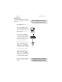
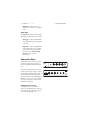
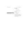
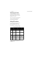
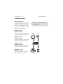
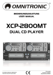
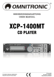
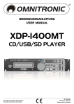
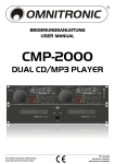
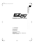
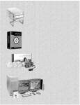
ADVC-100
Advanced Digital Video Converter
PART NO. 000-10072-001
COPYRIGHT ©2001 CANOPUS CORPORATION
ALL RIGHTS RESERVED.
ii
Chapter 1 ADVC-100
Copyright
Regulations
It is illegal for anyone to violate any of the
rights provided by the copyright laws to
the owner of copyright, except for fair use
(mainly private noncommercial use).Also,
in certain cases copying is prohibited with
no exceptions. In no event shall Canopus
be liable for any direct or indirect damages
whatsoever arising from the use of
captured materials.
Warranty
Canopus is not responsible for any lost
profits, lost savings or other incidental or
consequential damages arising out of the
use of, or inability to use, this product.
This includes damage to property and, to
the extent permitted by law, damages for
personal injury. This warranty is in lieu of
all other warranties of merchantability and
fitness for a particular purpose.
Cautions
Please observe the following cautions when
using this product. If you have any
questions regarding the method of usage,
the descriptions herein, or any other
concerns, please contact the Canopus
Technical Support team Monday through
Friday, expect for public holidays and
company-specific holidays from 9am-5pm,
Monday-Thursday; 9am-3:30pm Fridays.
Canopus Corporation
Canopus Technical Support
711 Charcot Avenue
San Jose, CA 95131
408 954-4506 PHONE
408 954-4504 FAX
[email protected]
DANGER
The following conditions indicate the
potential for serious bodily injury or loss
off life.
Health precautions
In rare cases, flashing lights or stimulation
from the bright light of a computer
monitor display may trigger temporary
epileptic seizures or loss of consciousness.
It is believed that even individuals whom
have never experienced such symptoms
may be susceptible. If you or close relatives
have experienced any of these symptoms,
consult a doctor before using this product.
Do not use in environments
requiring a high degree of
reliability and safety
This product is not to be used in medical
devices or life support systems. The
characteristics of this product are not
suited for use with such systems.
Protect against static electricity
An electrostatic discharge may damage
components of this product. Do not
directly touch any of the connectors or
component surfaces.
Static electricity can be generated on
clothing and on people. Before handling
the product, discharge static electricity
Canopus Corporation
from your body by touching a grounded
metal surface.
Do not disassemble
Do not remove the cover or modify the
ADVC-100. Fire, electric shock or
malfunction may result. For internal
inspection or repair, please contact your
system integrator or Canopus directly.
Do not operate at other than the
specified voltage
Do not operate at other than the specified
voltages of AC 100–240V. Operation at
other than the rated voltage may result in
fire or malfunction.
Do not operate with other than the
specified power supply
Do not operate with other than the
specified AC adapter, or with a car power
supply. Such operation may result in fire or
malfunction.
Handle the AC adapter cord
carefully
Do not place heavy objects on top of the
cord, or place it near hot objects. Doing so
may damage the cord and result in fire,
electrical shock, or malfunction. Altering
the cord, or excessively bending or pulling
the cord may result in fire or electrical
shock. If the cord is damaged, please
contact your local retail outlet or Canopus
directly.
ADVC-100 Basic Instructions
iii
CAUTION
The following conditions indicate the
potential for bodily harm, damage to
hardware or loss of data.
Do not pull AC adapter cord when
disconnecting from electrical
outlet
When disconnecting the AC adapter cord,
pull on the plug, not the cord itself.
Pulling on the cord can damage the cord
and may result in fire or electric shock.
Do not touch AC adapter with wet
hands
Do not disconnect or plug in the AC
adapter when your hands are wet. Contact
with water may result in electric shock, fire
or damage.
Do not setup in an area that
becomes hot
Do not setup in an area exposed to direct
sunlight or near a heating apparatus. The
heat can accumulate, causing burns, fire or
damage. Also, the unit may become
deformed or change color.
Do not setup other than the
prescribed method
Do not setup in a manner other than
prescribed. Do not use while wrapped in
cloth or plastic. Heat can accumulate,
causing burns, fire or damage.
If product will not be used for an
extended period
If this product will not to be used for an
extended period of time, disconnect the
AC adapter from the electrical outlet.
iv
Chapter 1 ADVC-100
Product Notes
1. Unauthorized copying of a portion
or the entirety of this product is
prohibited.
2. The description and specifications
of this product are subject to
future change without notice.
3. The description of this product has
been prepared to be as complete as
possible. If the reader is aware of
any questionable points, errors or
omissions, please contact
Canopus.
4. The company assumes no liability
for the results of practical
application, regardless of item (3)
above.
5. Regardless of whether negligence
occurs during usage, the company
assumes no liability, even if there is
a claim, for extraordinary,
incidental or derivative loss,
including the loss of profits, that
arise during practical application
of this product.
6. The analysis, reverse engineering,
decompiling and disassembling of
the software, hardware or manuals
that accompany this product, and
all other related products including
miscellaneous supplemental items,
are prohibited.
7. Canopus, as written in both
English and Japanese, and its logo
Canopus Corporation
are registered trademarks of
Canopus Co., Ltd.
8. ADVC-100 is a trademark of
Canopus Co., Ltd.
9. MS and Windows are registered
trademarks of Microsoft
Corporation in the US. Other
product names and related items
are trademarks or registered
trademarks of their respective
companies.
10. For the purpose of reading in
JPEG images, the ADVC-100
firmware incorporates a part of the
results of the Independent JPEG
Group.
Canopus Corporation
About the
Documentation
This document is the ADVC-100 User
Manual.
Information not listed in this document
may be listed elsewhere.
In cases where there is a difference between
a description in this document and an
actual operation method, the actual
operation method takes precedence.
This document is written for users capable
of performing basic PC operations. If there
is no special description of an operation,
perform that operation in the same
manner as a general PC operation.
This document refers to Microsoft’s
Windows 2000 operating system as
Windows 2000.
To simplify the descriptions, the actual
product may differ from the illustrations
and screenshots.
ADVC-100 Basic Instructions
v
vi
Chapter 1 ADVC-100
Canopus Corporation
1
ADVC-100
Basic Instructions
The ADVC-100 is a simple solution for
converting your S-VHS and Hi8 analog
tapes to DV in realtime. This manual
guides you through the basics of analog/
digital conversion. Package contents
include:
• ADVC-100 unit
• IEEE 1394 DV Cable (4 pin-6 pin)
• AC Adapter
• Video Cable (S-Video/Composite)
2
Chapter 1 ADVC-100
Canopus Corporation
QuickStart
If you want to jump right in and use the
ADVC-100, simply plug it in and follow
these steps.
If you are capturing PAL video, you need
change the DIP switch settings. For more
info, see Setting DIP switches on page 8.
1. Push the Power button on the
back of the unit.
2. Connect the IEEE 1394 cable to
the unit. The larger 6-pin end
goes into the back of the box, and
the smaller 4-pin end goes into
the capture card.
IEEE 1394/
Desktop PC
w/DV connection
If your computer’s IEEE 1394
ports are of the 6-pin variety, you
can reverse the cable and plug 4pin end into the 4-pin port on the
front of the unit and the 6-pin
end into your computer.
3. If you are capturing video from an
analog camera, make sure the
ADVC-100 is set to Analog In
and that the camera is connected
to the unit’s S-Video or composite
ports on the front of the unit.
DV
Camcorder
If you are exporting video to an
analog camera, make sure the
ADVC-100 is set to Digital In
and that the camera is connected
to the unit’s S-Video or composite
ports on the back of the unit.
4. You can now open your editing
application and begin capturing
video.
Deck control via software is not available
when using the ADVC-100, so you’ll have
to manually start and stop your captures.
Canopus Corporation
ADVC-100 Basic Instructions
3
ADVC-100 Basics
The front of the ADVC-100 contains
inputs for composite, S-Video and DV.
The DV input is a 4-pin IEEE 1394
(FireWire, i.Link) port and can do both
input and output.
DV I/O
VIDEO IN
AUDIO IN
S VIDEO OUT
VIDEO OUT
R-AUDIO OUT-L
POWER
DC IN 5V
The IMS function works with Canopus DV
Products and may not work with Apple and
OHCI devices.
Power button
To turn on the ADVC-100, make sure
the power cord is plugged into the back
of the unit and into a working electrical
outlet. Then press the Power button on
the back of the unit.
Auto (IMS) mode
The ADVC-100’s IMS (Intelligent Mode
Selector) mode can automatically
determine whether you are importing
digital or analog video, In this mode, the
unit automatically detects if there is
analog or DV input and switches to the
appropriate mode.
To enable this mode, make sure DIP
switch 6 is in the ON position. For more
information on DIP switches, see Setting
DIP switches on page 8.
L-AUDIO-R
INPUT SELECT
STATUS
ADVC-100
Advanceced DV Converter
DIGITAL IN
ANALOG IN
VIDEO IN
S VIDEO IN
DV I/O
Input Select button
The Input Select button on the top of
the unit lets you toggle between Digital
In and Analog In modes. A blue light
signifies which mode the ADVC-100 is
using. The Input Select button will not
work while the both status lights are
blinking.
• Analog In — Indicates that the
ADVC-100 is ready to receive analog
video.
4
Chapter 1 ADVC-100
Canopus Corporation
• Digital In — Indicates that the
ADVC-100 is ready to receive digital
video.
Status light
The Status light indicates separate things
depending on which mode you are using.
• Analog In — The status light blinks
when a Macrovision-protected signal
is detected.
• Digital In — The status light blinks
when the DV audio is set at 32kHz
12bit, which is used for 4-channel
DV audio. See 4-channel mixing
mode on page 10 for more
information.
Connection Ports
The ADVC-100 has connection ports for
both S-Video and composite input, as
well as a 4-pin IEEE 1394 input/output
port.
The back of the unit has ports for both
S-Video and composite output, as well as
a 6-pin IEEE 1394 input/output. There is
also an additional S-Video input and
Audio In, which uses a standard mini-jack
interface. For best results, you should use
the S-Video composite conversion table
included in the package.
Analog input connectors
A priority order is set to the Input
connectors. If all analog input connectors
are used at the same time, the connectors
are used in the following order:
L-AUDIO-R
VIDEO IN
S VIDEO IN
DV I/O
SELECT
STATUS
C-100
DV Converter
ANALOG IN
DV I/O
VIDEO IN
AUDIO IN
S VIDEO OUT
VIDEO OUT
R-AUDIO OUT-L
DC IN 5V
Canopus Corporation
ADVC-100 Basic Instructions
5
Video Input
1. S-video (Front)
2. Composite (Front)
3. S-Video/Composite (Back)
The unit detects if there is a cable attached
to the connector, regardless if there is a
signal coming in or not.
Audio Input
1. Front L/R RCA jack
2. Back minijack
If you have two video sources that you
use regularly, you should connect the one
that is more frequently used to the back,
and connect the other to the front only
when you are using it.
6
Chapter 1 ADVC-100
Canopus Corporation
2
ADVC-100
Using the ADVC-100
This chapter explains basic instructions
for using the ADVC-100.
8
Chapter 2 ADVC-100
Canopus Corporation
Powering up the unit
To turn on the ADVC-100, press the
power button on the back of the unit.
The three lights on the front of the unit
illuminate for 5 seconds.
After that, depending on the DIP switch
(switch 5) setting, the Analog In or
Digital In lights will illuminate.
Setting DIP switches
Use the DIP switches on the bottom of
the unit to modify the ADVC-100’s
functionality. Make sure the power is
turned off before you make any changes.
Table 1: DIP Switch Settings
No.
Mode
OFF
ON
1
Video Format
NTSC
PAL
2
NTSC
Setup Level
O IRE
7.5 IRE
3
Locked
Audio
Mode
Locked
Unlocked
4
Audio Mode
48kHz/16-bit
32kHz/12-bit
5
Power-on
Input Mode
Analog
Digital
6
Input Select
Mode
Manual
Auto (IMS)
By default, all of the DIP switches are in
the OFF position.
Canopus Corporation
ADVC-100
Using the ADVC-100
9
• Video Format — toggles between
capturing NTSC and PAL video.
The ADVC-100 is set to capture
NTSC video by default.
• NTSC Setup Level — toggles
between 0 IRE (Japan NTSC) and
7.5 IRE (USA NTSC).
• Locked Audio Mode — toggles
between capturing locked audio or
unlocked audio. If you are capturing
a lot of long clips, you should leave
this switch in the OFF position to
make sure the audio stays locked to
the video.
• Audio Mode — toggles between
48kHz/16-bit 2-channel audio and
32kHz/12-bit 4-channel audio. See
Setting 4-channel mixing mode on
page 10 for more information.
• Power-on Input Mode — toggles
between Analog and Digital modes
when you first turn on the unit. If
you primarily capture analog video,
you should set this to the OFF
position so the unit is in Analog In
mode when you turn it on.
• Input Select Mode — toggles
between Manual and Auto (IMS)
mode. In Auto (IMS) mode, the unit
detects whether there is analog or
DV input. For example, if you
connect an analog camera to the
unit, it automatically switches to
Analog In mode, and the Analog In
status light illuminates.
10
Chapter 2 ADVC-100
4-channel mixing mode
When encoding DV to analog in 32kHz
mode, the unit can be set to either:
1. Use the main audio channel
2. Mix main and sub channel at
50% each.
Setting 4-channel mixing mode
1. Set DIP switch 4 to the OFF
position.
2. Press the Input Select and Power
buttons at the same time
3. The Status light illuminates and
switches audio modes.
Color Bar output
Press the Input Select button for three
seconds to output color bars from the
analog output. Press the select button
again to resume analog output. Turning
the unit off also returns it to normal
output mode.
Macrovision detection
When Macrovision signals are detected by
the ADVC-100:
• The brightness and contrast for both
analog and DV output are lowered.
• The Status light blinks
Canopus Corporation
Canopus Corporation
ADVC-100 Using the ADVC-100
11
DVCAM support
When you are connecting to a DVCAM
unit, set DIP switch 3 to the OFF
position to set the ADVC-100 to Locked
Audio Mode.
Video signals from game
consoles
If you are capturing from a video source
with irregular video signals, such as game
consoles, you may hear audio noise in the
captured video. If this happens, try
setting DIP switch 3 to the ON position
so the audio is unlocked.
12
Chapter 2 ADVC-100
Canopus Corporation
1394 hub function
Video input selector
You can connect two DV devices to the
unit and share one analog device, such as
a monitor, for output. Simply set DIP
switch 6 to the ON position to enable
auto input select. There are four possible
scenarios for this functionality.
DV device 1=play
DV device 2=stop
Signal from 1 will be sent to 2 and analog
output. Analog input will be ignored.
This function may not be supported with
certain DV devices.
Monitor
(Analog Out)
DV Device 2
DV device 1=stop
DV device 2= play
Signal from 2 will be sent to 1 and analog
output. Analog input will be ignored.
DV device 1 = play
DV device 2= play
Signal will be irregular and output will be
unstable. Stop one of the DV devices.
DV device 1 = stop
DV device 2= stop
Analog signal will be sent to both DV
devices and also to analog output.
VHS/S-VHS/ß/EDß
(Analog In)
DV Device 1
Canopus Corporation
ADVC-100 Using the ADVC-100
13
Using with Canopus DV
products
The ADVC-100 can be used with the
following Canopus DV products:
• EZDV
• DVRaptor
• DVRaptor-RT
Set DIP switch 6 setting to the ON
position to enable the auto input select.
See Auto (IMS) mode on page 3 for
more information.
Connecting to your Canopus
capture card
When the ADVC-100 is connected to
your Canopus capture card, you can
perform the following functions:
• DV devices can be controlled directly
from the Canopus Edit/Video
software.
• Switch the DV device to OFF to use
the analog input.
• When you playback from the hard
drive, the signal will be sent out to
the DV device and analog output.
• Switch DV device to ON to capture
from DV device to hard drive.
14
Chapter 2 ADVC-100
Canopus Corporation