1
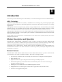
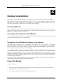
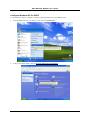
DSL-300G+ ADSL Modem User’s Guide (Sep 2002) 651L300G+015 DSL-300G+ ADSL Modem User’s Guide Wichtige Sicherheitshinweise 1. Bitte lesen Sie sich diese Hinweise sorgfältig durch. 2. Heben Sie diese Anleitung für den spätern Gebrauch auf. 3. Vor jedem Reinigen ist das Gerät vom Stromnetz zu trennen. Vervenden Sie keine Flüssig- oder Aerosolreiniger. Am besten dient ein angefeuchtetes Tuch zur Reinigung. 4. Um eine Beschädigung des Gerätes zu vermeiden sollten Sie nur Zubehörteile verwenden, die vom Hersteller zugelassen sind. 5. Das Gerät is vor Feuchtigkeit zu schützen. 6. Bei der Aufstellung des Gerätes ist auf sichern Stand zu achten. Ein Kippen oder Fallen könnte Verletzungen hervorrufen. Verwenden Sie nur sichere Standorte und beachten Sie die Aufstellhinweise des Herstellers. 7. Die Belüftungsöffnungen dienen zur Luftzirkulation die das Gerät vor Überhitzung schützt. Sorgen Sie dafür, daß diese Öffnungen nicht abgedeckt werden. 8. Beachten Sie beim Anschluß an das Stromnetz die Anschlußwerte. 9. Die Netzanschlußsteckdose muß aus Gründen der elektrischen Sicherheit einen Schutzleiterkontakt haben. 10. Verlegen Sie die Netzanschlußleitung so, daß niemand darüber fallen kann. Es sollete auch nichts auf der Leitung abgestellt werden. 11. Alle Hinweise und Warnungen die sich am Geräten befinden sind zu beachten. 12. Wird das Gerät über einen längeren Zeitraum nicht benutzt, sollten Sie es vom Stromnetz trennen. Somit wird im Falle einer Überspannung eine Beschädigung vermieden. 13. Durch die Lüftungsöffnungen dürfen niemals Gegenstände oder Flüssigkeiten in das Gerät gelangen. Dies könnte einen Brand bzw. Elektrischen Schlag auslösen. 14. Öffnen Sie niemals das Gerät. Das Gerät darf aus Gründen der elektrischen Sicherheit nur von authorisiertem Servicepersonal geöffnet werden. 15. Wenn folgende Situationen auftreten ist das Gerät vom Stromnetz zu trennen und von einer qualifizierten Servicestelle zu überprüfen: a – Netzkabel oder Netzstecker sint beschädigt. b – Flüssigkeit ist in das Gerät eingedrungen. c – Das Gerät war Feuchtigkeit ausgesetzt. d – Wenn das Gerät nicht der Bedienungsanleitung ensprechend funktioniert oder Sie mit Hilfe dieser Anleitung keine Verbesserung erzielen. e – Das Gerät ist gefallen und/oder das Gehäuse ist beschädigt. f – Wenn das Gerät deutliche Anzeichen eines Defektes aufweist. 16. Bei Reparaturen dürfen nur Orginalersatzteile bzw. den Orginalteilen entsprechende Teile verwendet werden. Der Einsatz von ungeeigneten Ersatzteilen kann eine weitere Beschädigung hervorrufen. 17. Wenden Sie sich mit allen Fragen die Service und Repartur betreffen an Ihren Servicepartner. Somit stellen Sie die Betriebssicherheit des Gerätes sicher. 18. Zum Netzanschluß dieses Gerätes ist eine geprüfte Leitung zu verwenden, Für einen Nennstrom bis 6A und einem Gerätegewicht großer 3kg ist eine Leitung nicht leichter als H05VV-F, 3G, 0.75mm2 einzusetzen Limited Warranty Hardware: D-LINK WARRANTS EACH OF ITS HARDWARE PRODUCTS TO BE FREE FROM DEFECTS IN WORKMANSHIP AND MATERIALS UNDER NORMAL USE AND SERVICE FOR A PERIOD COMMENCING ON THE DATE OF PURCHASE FROM D-LINK OR ITS AUTHORIZED RESELLER AND EXTENDING FOR THE LENGTH OF TIME STIPULATED BY THE AUTHORIZED RESELLER OR D-LINK BRANCH OFFICE NEAREST TO THE PLACE OF PURCHASE. THIS WARRANTY APPLIES ON THE CONDITION THAT THE PRODUCT REGISTRATION CARD IS FILLED OUT AND RETURNED TO A D-LINK OFFICE WITHIN NINETY (90) DAYS OF PURCHASE. A LIST OF D-LINK OFFICES IS PROVIDED AT THE BACK OF THIS MANUAL, TOGETHER WITH A COPY OF THE REGISTRATION CARD. IF THE PRODUCT PROVES DEFECTIVE WITHIN THE APPLICABLE WARRANTY PERIOD, D-LINK WILL PROVIDE REPAIR OR REPLACEMENT OF THE PRODUCT. D-LINK SHALL HAVE THE SOLE DISCRETION WHETHER TO REPAIR OR REPLACE, AND REPLACEMENT PRODUCT MAY BE NEW OR RECONDITIONED. REPLACEMENT PRODUCT SHALL BE OF EQUIVALENT OR BETTER SPECIFICATIONS, RELATIVE TO THE DEFECTIVE PRODUCT, BUT NEED NOT BE IDENTICAL. ANY PRODUCT OR PART REPAIRED BY D-LINK PURSUANT TO THIS WARRANTY SHALL HAVE A WARRANTY PERIOD OF NOT LESS THAN 90 DAYS, FROM DATE OF SUCH REPAIR, IRRESPECTIVE OF ANY EARLIER EXPIRATION OF ORIGINAL WARRANTY PERIOD. WHEN D-LINK PROVIDES REPLACEMENT, THEN THE DEFECTIVE PRODUCT BECOMES THE PROPERTY OF D-LINK. ii DSL-300G+ ADSL Modem User’s Guide WARRANTY SERVICE MAY BE OBTAINED BY CONTACTING A D-LINK OFFICE WITHIN THE APPLICABLE WARRANTY PERIOD, AND REQUESTING A RETURN MATERIAL AUTHORIZATION (RMA) NUMBER. IF A REGISTRATION CARD FOR THE PRODUCT IN QUESTION HAS NOT BEEN RETURNED TO D-LINK, THEN A PROOF OF PURCHASE (SUCH AS A COPY OF THE DATED PURCHASE INVOICE) MUST BE PROVIDED. IF PURCHASER'S CIRCUMSTANCES REQUIRE SPECIAL HANDLING OF WARRANTY CORRECTION, THEN AT THE TIME OF REQUESTING RMA NUMBER, PURCHASER MAY ALSO PROPOSE SPECIAL PROCEDURE AS MAY BE SUITABLE TO THE CASE. AFTER AN RMA NUMBER IS ISSUED, THE DEFECTIVE PRODUCT MUST BE PACKAGED SECURELY IN THE ORIGINAL OR OTHER SUITABLE SHIPPING PACKAGE TO ENSURE THAT IT WILL NOT BE DAMAGED IN TRANSIT, AND THE RMA NUMBER MUST BE PROMINENTLY MARKED ON THE OUTSIDE OF THE PACKAGE. THE PACKAGE MUST BE MAILED OR OTHERWISE SHIPPED TO D-LINK WITH ALL COSTS OF MAILING/SHIPPING/INSURANCE PREPAID. D-LINK SHALL NEVER BE RESPONSIBLE FOR ANY SOFTWARE, FIRMWARE, INFORMATION, OR MEMORY DATA OF PURCHASER CONTAINED IN, STORED ON, OR INTEGRATED WITH ANY PRODUCT RETURNED TO D-LINK PURSUANT TO THIS WARRANTY. ANY PACKAGE RETURNED TO D-LINK WITHOUT AN RMA NUMBER WILL BE REJECTED AND SHIPPED BACK TO PURCHASER AT PURCHASER'S EXPENSE, AND D-LINK RESERVES THE RIGHT IN SUCH A CASE TO LEVY A REASONABLE HANDLING CHARGE IN ADDITION MAILING OR SHIPPING COSTS. Software: WARRANTY SERVICE FOR SOFTWARE PRODUCTS MAY BE OBTAINED BY CONTACTING A D-LINK OFFICE WITHIN THE APPLICABLE WARRANTY PERIOD. A LIST OF D-LINK OFFICES IS PROVIDED AT THE BACK OF THIS MANUAL, TOGETHER WITH A COPY OF THE REGISTRATION CARD. IF A REGISTRATION CARD FOR THE PRODUCT IN QUESTION HAS NOT BEEN RETURNED TO A D-LINK OFFICE, THEN A PROOF OF PURCHASE (SUCH AS A COPY OF THE DATED PURCHASE INVOICE) MUST BE PROVIDED WHEN REQUESTING WARRANTY SERVICE. THE TERM "PURCHASE" IN THIS SOFTWARE WARRANTY REFERS TO THE PURCHASE TRANSACTION AND RESULTING LICENSE TO USE SUCH SOFTWARE. D-LINK WARRANTS THAT ITS SOFTWARE PRODUCTS WILL PERFORM IN SUBSTANTIAL CONFORMANCE WITH THE APPLICABLE PRODUCT DOCUMENTATION PROVIDED BY D-LINK WITH SUCH SOFTWARE PRODUCT, FOR A PERIOD OF NINETY (90) DAYS FROM THE DATE OF PURCHASE FROM D-LINK OR ITS AUTHORIZED RESELLER. D-LINK WARRANTS THE MAGNETIC MEDIA, ON WHICH D-LINK PROVIDES ITS SOFTWARE PRODUCT, AGAINST FAILURE DURING THE SAME WARRANTY PERIOD. THIS WARRANTY APPLIES TO PURCHASED SOFTWARE, AND TO REPLACEMENT SOFTWARE PROVIDED BY D-LINK PURSUANT TO THIS WARRANTY, BUT SHALL NOT APPLY TO ANY UPDATE OR REPLACEMENT WHICH MAY BE PROVIDED FOR DOWNLOAD VIA THE INTERNET, OR TO ANY UPDATE WHICH MAY OTHERWISE BE PROVIDED FREE OF CHARGE. D-LINK'S SOLE OBLIGATION UNDER THIS SOFTWARE WARRANTY SHALL BE TO REPLACE ANY DEFECTIVE SOFTWARE PRODUCT WITH PRODUCT WHICH SUBSTANTIALLY CONFORMS TO D-LINK'S APPLICABLE PRODUCT DOCUMENTATION. PURCHASER ASSUMES RESPONSIBILITY FOR THE SELECTION OF APPROPRIATE APPLICATION AND SYSTEM/PLATFORM SOFTWARE AND ASSOCIATED REFERENCE MATERIALS. D-LINK MAKES NO WARRANTY THAT ITS SOFTWARE PRODUCTS WILL WORK IN COMBINATION WITH ANY HARDWARE, OR ANY APPLICATION OR SYSTEM/PLATFORM SOFTWARE PRODUCT PROVIDED BY ANY THIRD PARTY, EXCEPTING ONLY SUCH PRODUCTS AS ARE EXPRESSLY REPRESENTED, IN D-LINK'S APPLICABLE PRODUCT DOCUMENTATION AS BEING COMPATIBLE. D-LINK'S OBLIGATION UNDER THIS WARRANTY SHALL BE A REASONABLE EFFORT TO PROVIDE COMPATIBILITY, BUT D-LINK SHALL HAVE NO OBLIGATION TO PROVIDE COMPATIBILITY WHEN THERE IS FAULT IN THE THIRD-PARTY HARDWARE OR SOFTWARE. D-LINK MAKES NO WARRANTY THAT OPERATION OF ITS SOFTWARE PRODUCTS WILL BE UNINTERRUPTED OR ABSOLUTELY ERROR-FREE, AND NO WARRANTY THAT ALL DEFECTS IN THE SOFTWARE PRODUCT, WITHIN OR WITHOUT THE SCOPE OF D-LINK'S APPLICABLE PRODUCT DOCUMENTATION, WILL BE CORRECTED. D-Link Offices for Registration and Warranty Service THE PRODUCT'S REGISTRATION CARD, PROVIDED AT THE BACK OF THIS MANUAL, MUST BE SENT TO A D-LINK OFFICE. TO OBTAIN AN RMA NUMBER FOR WARRANTY SERVICE AS TO A HARDWARE PRODUCT, OR TO OBTAIN WARRANTY SERVICE AS TO A SOFTWARE PRODUCT, CONTACT THE D-LINK OFFICE NEAREST YOU. AN ADDRESS/TELEPHONE/FAX/E-MAIL/WEB SITE LIST OF D-LINK OFFICES IS PROVIDED IN THE BACK OF THIS MANUAL. LIMITATION OF WARRANTIES IF THE D-LINK PRODUCT DOES NOT OPERATE AS WARRANTED ABOVE, THE CUSTOMER'S SOLE REMEDY SHALL BE, AT D-LINK'S OPTION, REPAIR OR REPLACEMENT. THE FOREGOING WARRANTIES AND REMEDIES ARE EXCLUSIVE AND ARE IN LIEU OF ALL OTHER WARRANTIES, EXPRESSED OR IMPLIED, EITHER IN FACT OR BY OPERATION OF LAW, STATUTORY OR OTHERWISE, INCLUDING WARRANTIES OF MERCHANTABILITY AND FITNESS FOR A PARTICULAR PURPOSE. D-LINK NEITHER ASSUMES NOR AUTHORIZES ANY OTHER PERSON TO ASSUME FOR IT ANY OTHER LIABILITY IN CONNECTION WITH THE SALE, INSTALLATION MAINTENANCE OR USE OF D-LINK'S PRODUCTS D-LINK SHALL NOT BE LIABLE UNDER THIS WARRANTY IF ITS TESTING AND EXAMINATION DISCLOSE THAT THE ALLEGED DEFECT IN THE PRODUCT DOES NOT EXIST OR WAS CAUSED BY THE CUSTOMER'S OR ANY THIRD PERSON'S MISUSE, NEGLECT, IMPROPER INSTALLATION OR TESTING, UNAUTHORIZED ATTEMPTS TO REPAIR, OR ANY OTHER CAUSE BEYOND THE RANGE OF THE INTENDED USE, OR BY ACCIDENT, FIRE, LIGHTNING OR OTHER HAZARD. iii DSL-300G+ ADSL Modem User’s Guide LIMITATION OF LIABILITY IN NO EVENT WILL D-LINK BE LIABLE FOR ANY DAMAGES, INCLUDING LOSS OF DATA, LOSS OF PROFITS, COST OF COVER OR OTHER INCIDENTAL, CONSEQUENTIAL OR INDIRECT DAMAGES ARISING OUT THE INSTALLATION, MAINTENANCE, USE, PERFORMANCE, FAILURE OR INTERRUPTION OF A D- LINK PRODUCT, HOWEVER CAUSED AND ON ANY THEORY OF LIABILITY. THIS LIMITATION WILL APPLY EVEN IF D-LINK HAS BEEN ADVISED OF THE POSSIBILITY OF SUCH DAMAGE. IF YOU PURCHASED A D-LINK PRODUCT IN THE UNITED STATES, SOME STATES DO NOT ALLOW THE LIMITATION OR EXCLUSION OF LIABILITY FOR INCIDENTAL OR CONSEQUENTIAL DAMAGES, SO THE ABOVE LIMITATION MAY NOT APPLY TO YOU. Trademarks Copyright 2000 D-Link Corporation. Contents subject to change without prior notice. D-Link is a registered trademark of D-Link Corporation/D-Link Systems, Inc. All other trademarks belong to their respective proprietors. Copyright Statement No part of this publication may be reproduced in any form or by any means or used to make any derivative such as translation, transformation, or adaptation without permission from D-Link Corporation/D-Link Systems Inc., as stipulated by the United States Copyright Act of 1976 FCC Warning This device complies with part 15 of the FCC Rules. Operation is subject to the following two conditions: (1) This device may not cause harmful interference, and (2) this device must accept any interference received, including interference that may cause undesired operation. This equipment has been tested and found to comply with the limits for a Class B digital device, pursuant to part 15 of the FCC Rules. These limits are designed to provide reasonable protection against harmful interference in a residential installation. This generates, uses and can radiate radio frequency energy and, if not installed and used in accordance with the instructions, may cause harmful interference to radio communications. However, there is no guarantee that interference will not occur in a particular installation. If this equipment does cause harmful interference to radio or television reception, which can be determined by turning equipment off and on, the user is encouraged to try to correct the interference by one or more of the following measures: - Reorient or relocate the receiving antenna. - Increase the separation between the equipment and receiver. - Connect the equipment into an outlet on a circuit different from that to which the receiver is connected. - Consult the dealer or an experienced radio/TV technician for help. iv CONTENTS ABOUT THIS USER’S GUIDE ................................................................................. VII Before You Start ........................................................................................................................................... vii Requirements for Installation............................................................................................................................ vii INTRODUCTION ........................................................................................................ 1 Modem Description and Operation ..................................................................................................................... 1 Modem Features.............................................................................................................................................. 1 Front Panel ...................................................................................................................................................... 2 LED Indicators................................................................................................................................................ 2 Rear Panel ....................................................................................................................................................... 3 Packing List .................................................................................................................................................... 3 HARDWARE INSTALLATION ................................................................................... 4 Connect ADSL Line........................................................................................................................................ 4 Connecting One Computer to the Modem ...................................................................................................... 4 Connecting a Local Ethernet Network to the Modem..................................................................................... 4 Power On Modem ............................................................................................................................................... 4 FIRST TIME SET UP.................................................................................................. 6 Configuring Your Computer for DHCP.............................................................................................................. 6 Access the Web-based Configuration Manager ............................................................................................... 13 Configure the Internet Connection................................................................................................................ 14 PPPoE Connections....................................................................................................................................... 14 Changing the Connection Type......................................................................................................................... 15 Change Connection Type to PPPoA ............................................................................................................. 16 Change Connection Type to IPoA ................................................................................................................ 18 Change Connection Type to RFC 1483 Bridge............................................................................................. 19 USING THE WEB MANAGER ..................................................................................20 Web-based Configuration Manager GUI ...................................................................................................... 20 System Setting (VPI/VCI Settings)............................................................................................................... 21 PPP Account Configuration .......................................................................................................................... 22 IPoA Account Configuration ........................................................................................................................ 23 Summary ....................................................................................................................................................... 24 Update Firmware........................................................................................................................................... 26 Accounts Management.................................................................................................................................. 27 TECHNICAL SPECIFICATIONS...............................................................................28 Figures Figure 1. Front Panel Display ................................................................................................................................. 2 Figure 2. Rear Panel Connections........................................................................................................................... 3 Figure 3. PC to Modem Ethernet Connection ..................................................................... 錯誤! 尚未定義書籤。 Figure 4. Account Configuration Menu – First Time Set Up................................................................................ 13 Figure 5. Changing Connection Type ................................................................................................................... 15 Figure 6. PPPoA Account Configuration – Initial Set Up..................................................................................... 16 Figure 7. IPoA Account Configuration – Initial Set Up........................................................................................ 18 Figure 8. RFC 1483 Bridge Account Configuration ............................................................................................. 19 Figure 9 Configuration Manager........................................................................................................................... 20 Figure 10. System Setting Menu (PPPoE) ............................................................................................................ 21 Figure 11. PPPoE Account Configuration ............................................................................................................ 22 Figure 12. IPoA Account Configuration ............................................................................................................... 23 Figure 13. Summary Statistics .............................................................................................................................. 24 Figure 14. Summary Statistics in Bridge Mode .................................................................................................... 25 Figure 15. Update Firmware ................................................................................................................................. 26 Figure 16. Accounts Management ........................................................................................................................ 27 DSL-300 ADSL Ethernet Modem User’s Guide About This User’s Guide This user’s guide instructs the reader to install the DSL-300G+ ADSL Modem and use it to connect a single computer to the Internet. If you are using a computer with a functioning Ethernet port, you can use the Quick Installation Guide to quickly establish your ADSL connection and access the Internet. Guide Overview Chapter 1 Introduction – A description of the Modem and its key features including Front and Rear panel diagrams. A packing list is included at the end of the chapter. Chapter 2 Hardware Installation – A description of alternatives for connecting the Modem to a single computer or to an Ethernet Local Area Network (LAN). Chapter 3 First Time Set Up – A step-by-step guide for configuring the Modem to communicate with a computer and establish the ADSL connection. Chapter 4 Using the Web Manager – An illustrated description of the various management functions used for configuring and monitoring the Modem. Management software is web-based and can be accessed using a standard web browser. Appendix A Technical Specifications – A list of hardware and software specifications including standards and protocols compliance. Before You Start Please read and make sure you understand all the prerequisites for proper installation of your new Modem. Have all the necessary information and equipment on hand before beginning the installation. Low Pass Filters Since ADSL and telephone services share the same copper wiring to carry their respective signals, a filtering mechanism may be necessary to avoid mutual interference. A low pass filter device (also called micro-filter or splitter) can be installed for each telephone that shares the line with the ADSL line. Micro-filters are easy to install passive devices that connect to the ADSL device and/or telephone using standard telephone cable. Ask your service provider for more information about the use of low pass filters with your installation. Requirements for Installation You will need a computer that meets the minimum requirements listed below to set up and use the Modem. In addition, it will be necessary to configure the device using information provided by your ADSL service provider or ISP. This information is used to establish the parameters of the ADSL connection and identify the Modem on the service provider’s network. Operating System Requirements The DSL-300G+ uses an HTML-based web interface for setup and management. The web configuration manager may be accessed using any operating system capable of running web browser software. Web Browser Any common web browser can be used to configure the Modem using the web configuration management software. The program is designed to work best with Microsoft Internet Explorer® version 5.0, Netscape Navigator® version 4.7, or later versions. The web browser must have Javascript enabled. Make sure Javascript has not been disabled system wide by other software (such as virus protection or web user security packages). vii DSL-300 ADSL Ethernet Modem User’s Guide Ethernet Adapter (NIC) Any computer using the Modem for Internet access, must have an Ethernet NIC (Network Interface Card) installed or a working Ethernet port. Most recently produced notebook computers are equipped with an Ethernet port. The system must have TCP/IP Protocol installed and enabled. If you have an Ethernet port installed, you probably already have TCP/IP enabled. The Modem is equipped with a DHCP server to automatically assign an IP address to computer using it. The computer must first be configured to receive this IP address from the Modem. Instruction for configuring Windows operating systems to become a “DHCP client” is provided in the section titled First Time Set Up. If you are using the Modem as a simple bridge (RFC 1483), additional software may be needed for the computer or server connected to the Modem (on the LAN side). Your ADSL service provider or ISP will give you more information. Connection Type There are different methods available to make the connection from your computer (through the Modem) to the Internet (through your ADSL service). In order to properly configure the Modem, it is necessary to know what connection type is used to provide your ADSL connection. The Modem supports the following connection types: ♦ PPP over ATM (RFC 2364) used by default ♦ PPP over Ethernet (RFC 2516) ♦ IP over ATM (RFC 1577) ♦ Ethernet over ATM (RFC 1483) Account Information (User Name and Password) A User Name and Password used to identify your account on the service provider’s network. For PPPoE and PPPoA connections, the account information is stored in the Modem’s memory. If your connection uses Ethernet over ATM (RFC 1483) it is likely that you will also need a user name and password. For RFC 1483 connections however, the account information is actually stored on your computer along with connection software you must install on your system. ACCOUNT INFORMATION User Name: Password: Bridged Ethernet Connections (RFC 1483) All connections to the Internet require a unique global IP address. For bridged connections, the global IP settings must reside in your computer. Your ADSL service provider or ISP may have given you a CD with software that you must install on computer. Ask you service provider for more information. viii DSL-300 ADSL Ethernet Modem User’s Guide IPoA Connections (RFC 1577) IP over ATM connections may require global IP settings for the device. Your service provider will give you IP settings information if needed. Global IP Settings for IPoA Connections IP Address: Netmask: Gateway: DNS: Additional Settings If your ISP or ADSL service provider has instructed to change the VPI/VCI settings, there is a special menu, the System Settings menu in the management software used to change this. Some accounts using PPPoE may be instructed to change the AC Name. The AC Name is changed in the same menu. See the section titled Using the Web Manager for instructions on changing these settings. ix DSL-300 ADSL Modem User’s Guide 1 Introduction This section provides a brief description of the Modem, its associated technologies and a list of Modem features. ADSL Technology Asymmetric Digital Subscriber Line (ADSL) is broadband access technology that provides high-speed digital data transmission and interactive multimedia applications for business and residential customers over ordinary telephone line. ADSL greatly increases the signal carrying capacity of copper telephone lines without interfering with regular telephone services. For the ADSL user, this means faster downloads and more reliable connectivity. ADSL devices enable high-speed Internet access without any loss of quality or disruption of telephone services. ADSL provides a dedicated service over a single telephone line operating at speeds of up to 8 Mbps downstream and up to 640 Kbps upstream. A secure point-to-point connection is established between the user and the central office of the service provider. D-Link ADSL devices incorporate the recommendations of the ADSL Forum regarding framing, data format, and upper layer protocols. Modem Description and Operation The DSL-300G+ ADSL Modem is designed to provide a simple, cost-effective and secure ADSL Internet connection for your small to medium-sized private network. The ADSL connection technology enables many interactive multi-media applications such as video conferencing and collaborative computing. The Modem is easy to install and use. The DSL-300G+ connects to an Ethernet LAN or single computer via a standard Ethernet interface. The ADSL connection is made using ordinary twisted-pair telephone line with standard RJ-11 connectors. Modem Features The DSL-300G+ ADSL Ethernet Modem utilizes the latest ADSL enhancements to provide a reliable Internet portal suitable for most small to medium sized offices. DSL-300G+ advantages include: • Quick and easy installation with a user friendly web-based GUI for configuration and management • Built-in DHCP server • High data transfer rates; up to 8 Mbps downstream and up to 640 Kbps upstream • DSLAM interoperability; the auto-detect function automatically selects the correct connection type during the initialization process • MIB Support; built-in MIBs allow some SNMP management functions • Bridged Ethernet over ATM support; the DSL-300G+ supports RFC 2684 (also RFC 1483) • Firmware can be upgraded using TFTP 1 DSL-300 ADSL Modem User’s Guide Front Panel Place the Modem in a location where the LED indicators can be easily viewed. Power Status ADSL Ethernet Figure 1. Front Panel Display LED Indicators Power Steady green light indicates the unit is powered on. Status Lights steady green during power on self-test. Once the connection status has been settled, the light will blink green indicating normal operation. ADSL: Link ADSL: Act Ethernet: Link Ethernet: Act Steady green light indicates a valid ADSL connection. This will light after the ADSL negotiation process has been settled. Blinking green light indicates activity on the WAN interface (ADSL port). Steady green indicates an Ethernet connection. Blinking green indicates an activity on the Ethernet port. 2 DSL-300 ADSL Modem User’s Guide Rear Panel All cable connections to the Modem are made at the rear panel, including the Console port connection. The Console port is intended for use by a qualified telecommunications technician. Please do not attempt to configure the device through the Console connection. Power cord connects here Ethernet port, connect Ethernet cable here The factory reset button is located here. ADSL port, connect ADSL cable here Figure 2. Rear Panel Connections Packing List Open the shipping carton and carefully remove all items. In addition to this User's Guide, ascertain that you have: 1. One DSL-300G+ ADSL Modem 2. One User’s Guide 3. One twisted-pair telephone cable used for ADSL connection 4. One straight-through Ethernet cable 5. One AC power adapter suitable for your electric service 3 DSL-300 ADSL Modem User’s Guide 2 Hardware Installation In this chapter you will learn about the various connections you will need to make in order to use the Modem. When selecting the location for the Modem, allow ample room to access the connections on the rear panel. For convenience, try to place the Modem near your computer so you can monitor the LED indicators. Allow some space above the Modem for ventilation to avoid problems with overheating. Connect ADSL Line Use the twisted-pair ADSL cable (standard telephone cable) included with the Modem to connect it to your telephone line. Simply plug one end of the cable into the ADSL port (RJ-11 receptacle) on the rear panel of the Modem and insert the other end into the wall jack. Connecting One Computer to the Modem You can connect the Modem directly to a 10/100BASE-TX Ethernet adapter card (NIC) installed on a PC using the Ethernet cable provided as shown in this diagram. Connecting a Local Ethernet Network to the Modem The Modem may be connected to any 10/100BASE-TX Ethernet LAN. Any connection to an Ethernet concentrating device such as a switch or hub must operate at a speed of 10/100 Mbps only. When connecting the Modem to any Ethernet device that is capable of operating at speeds higher than 10Mbps, be sure that the device has auto-negotiation (NWay) enabled for the connecting port. Use standard twisted-pair cable with RJ-45 connectors. The RJ-45 port on the Modem is a crossed port (MDI-X). Follow standard Ethernet guidelines when deciding what type of cable to use to make this connection. When connecting the Modem directly to a PC or server use a normal straight-through cable. You should use a crossed cable when connecting the Modem to a normal (MDI-X) port on a switch or hub. Use a normal straight-through cable when connecting it to an uplink (MDI-II) port on a hub or switch. A valid connection will be indicated by the Ethernet Link LED indicator. The rules governing Ethernet cable lengths apply to the LAN to Modem connection. Be sure that the cable connecting the LAN to the Modem does not exceed 100 meters. Power On Modem To power on the device: 1. Insert the AC Power Adapter cord into the power receptacle located on the right side panel of the Modem and plug the adapter into a nearby power source. 2. You should see the Power LED indicator light up and remain lit. 4 DSL-300 ADSL Modem User’s Guide 5 DSL-300 ADSL Modem User’s Guide 3 First Time Set Up This chapter will show you how configure the Modem in order to establish the ADSL connection and ultimately a connection to the Internet. Any management software features that are directly concerned with establishing an Internet connection using ADSL are explained in the following chapter, Using the Web Configuration Manager. Make sure your computer’s Ethernet port is connected directly to the Modem as described in the previous chapter. If your computer has more than one Ethernet port, it is recommended that you disable the ports that are not connected to the Modem before configuring the device in order to avoid any potential for IP settings conflicts with other equipment. It may be necessary to change the IP settings on your system in order to access the management software used for Modem configuration. The Modem uses Dynamic Host Configuration Protocol (DHCP) to automatically assign an IP address to your computer. Your compute (more precisely your Ethernet port’s IP interface) must be configured to receive IP settings from the Modem. This means that your system must first be configured to become a DHCP client. Once your computer’s IP settings are configured to connect to the Modem, you can configure the Modem to suit the requirements of your ADSL service. Some users will not need to configure the device and will simply use the factory default settings for the Internet connection. Even in this case though, it is necessary that your computer be configured as a DHCP client. Note: There is a difference between a ”local” IP address and a “global” or “universal” IP address. You must configure your computer to receive its local IP settings from the Modem. To access the web-based configuration software, you use the local IP address of the Modem. The global IP address is used to identify your account on the larger network and ultimately on the Internet. For ADSL connections that use PPPoE, PPPoA or IPoA connection types, this global IP address information is stored on the Modem and has no effect on the IP address of your computer. For RFC 1483 Bridge connections, additionally software may need to be installed on your computer. In this case, once the Modem has been configured to act as a bridge, the global IP address information will actually be stored on your computer. When the Modem acts as a bridge it is said to be invisible, that is, the Modem itself does not have an IP address. Configuring Your Computer for DHCP In order to configure your system to receive IP settings from the Modem it must first have the TCP/IP protocol installed. If you have an Ethernet port on your computer is probably already has TCP/IP protocol installed. If you are using Windows XP the TCP/IP is enabled by default. Below is an illustrated example of how to configure a Windows XP system to automatically obtain IP settings form the Modem. Following this example is a step-bystep description of the procedures used on the other Windows operating systems to first check if the TCP/IP protocol has been installed, if it is not instruction are provided for installing it. Once the protocol has been installed you can configure the system to receive IP settings from the Modem. For computers running non-Windows operating systems, follow the instructions for you OS to allow the system to receive an IP address from the Modem, that is, configure the system to be a DHCP client. 6 DSL-300 ADSL Modem User’s Guide Configure Windows XP for DHCP Use the following steps to configure a computer running Windows XP to be a DHCP client. 1. From the Start menu on your desktop, go to click on Control Panel. 2. In the Control Panel folder, click on Network and Internet Connections. 7 DSL-300 ADSL Modem User’s Guide 3. In the Network and Internet Connections folder, click on Network Connections. 4. In the Network Connections folder, highlight the Local Area Connection icon by clicking on it once. A new option is revealed under Network Tabs in the left side panel. 8 DSL-300 ADSL Modem User’s Guide 5. Click on Change settings of the connection under Network Tabs. 6. In the General Tab of the Local Area Connection Properties menu, highlight Internet Protocol (TCP/IP) under “This connection uses the following items:” by clicking on it once. Click on the Properties button. 9 DSL-300 ADSL Modem User’s Guide 7. Select “Obtain an IP address automatically” by clicking once in the circle. Click the OK button. Your computer is now ready to use the Modem’s DHCP server. Windows 2000 First, check for the IP protocol and, if necessary, install it: 1. In the Windows task bar, click the Start button, point to Settings, and then click Control Panel. 2. Double-click the Network and Dial-up Connections icon. 3. In the Network and Dial-up Connections window, right-click the Local Area Connection icon, and then select Properties. 4. The Local Area Connection Properties dialog box displays with a list of currently installed network components. If the list includes Internet Protocol (TCP/IP), then the protocol has already been enabled, skip ahead to Configure Windows 2000 for DHCP. 5. If Internet Protocol (TCP/IP) does not display as an installed component, click Install. 6. In the Select Network Component Type dialog box, select Protocol, and then click Add. 7. Select Internet Protocol (TCP/IP) in the Network Protocols list, and then click OK. 8. You may be prompted to install files from your Windows 2000 installation CD or other media. Follow the instructions to install the files. 9. If prompted, click OK to restart your computer with the new settings. Configure Windows 2000 for DHCP 1. In the Control Panel, double-click the Network and Dial-up Connections icon. 2. In Network and Dial-up Connections window, right-click the Local Area Connection icon, and then select Properties. 3. In the Local Area Connection Properties dialog box, select Internet Protocol (TCP/IP), and then click Properties. 4. In the Internet Protocol (TCP/IP) Properties dialog box, click the button labeled Obtain an IP address automatically. 5. Double-click OK to confirm and save your changes, and then close the Control Panel. Your computer is now ready to use the Modem’s DHCP server. 10 DSL-300 ADSL Modem User’s Guide Windows ME First, check for the IP protocol and, if necessary, install it: 1. In the Windows task bar, click the Start button, point to Settings, and then click Control Panel. 2. Double-click the Network and Dial-up Connections icon. 3. In the Network and Dial-up Connections window, right-click the Network icon, and then select Properties. 4. The Network Properties dialog box displays with a list of currently installed network components. If the list includes Internet Protocol (TCP/IP), then the protocol has already been enabled. Skip ahead to Configure Windows ME for DHCP. 5. If Internet Protocol (TCP/IP) does not display as an installed component, click Add. 6. In the Select Network Component Type dialog box, select Protocol, and then click Add. 7. Select Microsoft in the Manufacturers box. 8. Select Internet Protocol (TCP/IP) in the Network Protocols list, and then click OK. 9. You may be prompted to install files from your Windows Me installation CD or other media. Follow the instructions to install the files. 10. If prompted, click OK to restart your computer with the new settings. Configure Windows ME for DHCP 1. In the Control Panel, double-click the Network and Dial-up Connections icon. 2. In Network and Dial-up Connections window, right-click the Network icon, and then select Properties. 3. In the Network Properties dialog box, select TCP/IP, and then click Properties. 4. In the TCP/IP Settings dialog box, click the Obtain and IP address automatically option. 5. Double-click OK twice to confirm and save your changes, and then close the Control Panel. Your computer is now ready to use the Modem’s DHCP server. Windows 95, 98 First, check for the IP protocol and, if necessary, install it: 1. In the Windows task bar, click the Start button, point to Settings, and then click Control Panel. Double-click the Network icon. 2. The Network dialog box displays with a list of currently installed network components. If the list includes TCP/IP, and then the protocol has already been enabled, skip to Configure IP Information Windows 95, 98. 3. If TCP/IP does not display as an installed component, click Add. The Select Network Component Type dialog box displays. 4. Select Protocol, and then click Add. The Select Network Protocol dialog box displays. 5. Click on Microsoft in the Manufacturers list box, and then click TCP/IP in the Network Protocols list box. 6. Click OK to return to the Network dialog box, and then click OK again. You may be prompted to install files from your Windows 95/98 installation CD. Follow the instructions to install the files. 7. Click OK to restart the PC and complete the TCP/IP installation. 11 DSL-300 ADSL Modem User’s Guide Configure Windows 95, 98 for DHCP 1. Open the Control Panel window, and then click the Network icon. 2. Select the network component labeled TCP/IP, and then click Properties. 3. If you have multiple TCP/IP listings, select the listing associated with your network card or adapter. 4. In the TCP/IP Properties dialog box, click the IP Address tab. 5. Click the Obtain an IP address automatically option. 6. Double-click OK to confirm and save your changes. You will be prompted to restart Windows. 7. Click Yes. When it has restarted your computer is ready to use the Modem’s DHCP server. Windows NT 4.0 workstations: First, check for the IP protocol and, if necessary, install it: 1. In the Windows NT task bar, click the Start button, point to Settings, and then click Control Panel. 2. In the Control Panel window, double click the Network icon. 3. In the Network dialog box, click the Protocols tab. 4. The Protocols tab displays a list of currently installed network protocols. If the list includes TCP/IP, then the protocol has already been enabled. Skip to “Configure IP Information” 5. If TCP/IP does not display as an installed component, click Add. 6. In the Select Network Protocol dialog box, select TCP/IP, and then click OK. You may be prompted to install files from your Windows NT installation CD or other media. Follow the instructions to install the files. 7. After all files are installed, a window displays to inform you that a TCP/IP service called DHCP can be set up to dynamically assign IP information. 8. Click Yes to continue, and then click OK if prompted to restart your computer. Configure Windows NT 4.0 for DHCP 1. Open the Control Panel window, and then double-click the Network icon. 2. In the Network dialog box, click the Protocols tab. 3. In the Protocols tab, select TCP/IP, and then click Properties. 4. In the Microsoft TCP/IP Properties dialog box, click the Obtain an IP address automatically option. 5. Click OK twice to confirm and save your changes, and then close the Control Panel. 12 DSL-300 ADSL Modem User’s Guide Access the Web-based Configuration Manager With your computer configured to receive its IP settings from the Modem, it can now access the web-based (HTML-based) configuration management software. Note: Be sure that the web browser on the computer is not configured to use a proxy server in the Internet settings. In Windows Internet Explorer, you can check if a proxy server is enabled using the following procedure: 1. In Windows, click on the START button, go to Settings and choose Control Panel. 2. In the Control Panel window, double-click on the Internet Options icon. 3. Click the Connections tab and click on the LAN Settings button. 4. Verify that the “Use proxy server” option is NOT checked. If it is checked, click in the checked box to deselect the option and click OK. To use the web-based management software, launch a suitable web browser and direct it to the IP address of the Router. Type in http:// followed by the default IP address, 192.168.0.1 in the address bar of the browser. The URL in the address bar should read: http://192.168.0.1. Press the Enter key or if you are using Internet Explorer click the “Go” button to the right of the URL field. A web page such as that seen below should appear. Figure 3. Account Configuration Menu – First Time Set Up 13 DSL-300 ADSL Modem User’s Guide Configure the Internet Connection Now that you have accessed the web-based manager, you can configure the device for connection to the Internet. For PPPoE and PPPoA connections, you will need to enter a User Name and Password used by your ISP or ADSL service provider for authentication purposes. This information is stored in the Modem’s memory and you will not need to enter this again. If you are using PPPoE on the Modem for your Internet connection and you have not been instructed to change any connection settings for the Modem, then all you need to do is to enter the authentication information (user name and password). If your ADSL service is using a “Bridged Ethernet” (RFC 1483) connection, your ISP or ADSL service provider will supply special software to install on your computer. This software will also require a user name and password for your account. In this case, the user name and password are stored in your computer’s memory. The default connection method used by the Modem is PPPoE. If you are using a PPPoA, IPoA, or Bridged Ethernet (RFC 1483) connection, you need to change the connection method. If you are using a connection type other than PPPoE, skip ahead to the section titled, Changing the Connection Type. Once the connection type has been changed, read the section corresponding to your ADSL service connection type to configure your Internet connection. PPPoE Connections In the Account Configuration window, follow these steps to establish the Internet connection using PPPoE: 1. In the User Name entry field, type the user name used to identify your account. 2. In the Password entry field, type the password used to authenticate your account 3. DO NOT change the Authentication method unless your ADSL service provider or ISP has instructed you to change it. By default, the pap protocol is selected. If you are told to change this, select chap from the pull-down menu. 4. Leave the Connect on Demand option enabled in the pull-down menu. This simply means that the Modem will begin the connection process when it restarts. 5. Leave Idle Time set to the 0. This tells the Modem to maintain the “always on” connection, even when you are not using the Internet. 6. Click OK. 7. A new message appears: 8. Click OK. The information you have just entered will be saved to the Modem’s flash memory. Note: If you have been instructed to change the VPI/VCI settings or to enter the AC Name information, skip ahead to the System Settings section in the next chapter. 14 DSL-300 ADSL Modem User’s Guide 9. The Modem is now ready to begin the process that establishes a connection to the Internet. This is known as the “negotiation” process since the Modem must first contact other computers on the network to verify your account information and negotiate the connection. Click on the Connect button to begin the negotiation. It will take a few seconds for verification and connection processes to be completed. Notice that the Connection Status field displays a message informing you that the Modem is now “Connecting…”; when the connection is established, this field displays the message “Connected”. When you see this message, you are connected to the Internet. Changing the Connection Type By default, the Modem is configured to use the PPPoE connection method for the connection to the Internet. If your ADSL service uses PPPoA, IPoA or “RFC 1483 Bridge” connection types you must first change the connection type and restart the Modem before you can establish a connection. Follow the instruction below for the type of connection you want to use. Figure 4. Changing Connection Type At the top of the Account Configuration menu you will see a pull-down menu labeled Connection Type. Use this to select the connection type used for your ADSL service. 15 DSL-300 ADSL Modem User’s Guide Change Connection Type to PPPoA To change the connection type to PPPoA and connect to the Internet, follow these steps: 1. In the Account Configuration window, select PPPoA from the Connection Type pull-down menu. The web page display will change to present this menu: Figure 5. PPPoA Account Configuration – Initial Set Up 2. DO NOT change the Encapsulation setting unless your ADSL service provider or ISP has instructed you to change it. By default, the LLC is selected. If you are told to change this, select VC Mux from the pull-down menu. 3. In the User Name entry field, type the user name used to identify your account. 4. In the Password entry field, type the password used to authenticate your account 5. DO NOT change the Authentication method unless your ADSL service provider or ISP has instructed you to change it. By default, the pap protocol is selected. If you are told to change this, select chap from the pull-down menu. 6. Leave the Connect on Demand option enabled in the pull-down menu. This simply means that the Modem will begin the connection process when it restarts. 7. Leave Idle Time set to the 0. This tells the Modem to maintain the “always on” connection, even when you are not using the Internet. 8. Click on the OK button. 16 DSL-300 ADSL Modem User’s Guide 9. A new message appears: 10. Click on the OK button. The information you have just entered will be saved to the Modem’s flash memory. Note: If you have been instructed to change the VPI/VCI settings, skip ahead to the System Settings section in the next chapter. 11. The Modem is now ready to begin the process that establishes a connection to the Internet. This is known as the “negotiation” process since the Modem must first contact other computers on the network to verify your account information and negotiate the connection. Click on the Connect button to begin the negotiation. It will take a few seconds for verification and connection processes to be completed. Notice that the Connection Status field displays a message informing you that the Modem is now “Connecting…”; when the connection is established, this field displays the message “Connected”. When you see this message, you are connected to the Internet. 17 DSL-300 ADSL Modem User’s Guide Change Connection Type to IPoA To change the connection type to IPoA and connect to the Internet, follow these steps: 1. In the Account Configuration window, select IPoA from the Connection Type pull-down menu. The web page display will change to present this menu: Figure 6. IPoA Account Configuration – Initial Set Up 2. DO NOT change the Encapsulation setting unless your ADSL service provider or ISP has instructed you to change it. By default, the LLC is selected. If you are told to change this, select VC Mux from the pull-down menu. 3. Type in the global IP settings for your account. The global IP settings are used to identify your account on the Internet. Your ISP or ADSL service provider should give you an IP Address and Netmask. Enter these numbers in the spaces provided. IP settings are written using dotted decimal notation, that is, an IP setting (such as an IP address) is written as a set of four numbers of up to three digits each separated by a period (also called “dot” or decimal point). Remember, these IP addresses are your “global” or “universal” IP settings. This has no effect on the IP address of your computer. The IP address of your computer as well as the IP address you used to connect to the Modem are both “local” IP addresses. 4. Additional IP settings must be entered so the Modem can be used to access the Internet and find web pages. These are the Gateway IP address and the DNS IP address. Enter these IP settings in the spaces provided. 5. Click the OK button. A message prompt appears informing you that it will take about a minute to save the information and restart the Modem. Click Yes to restart the Modem. Note: If you have been instructed to change the VPI/VCI settings, skip ahead to the System Settings section in the next chapter. 6. After restarting, the Modem will be connected and ready for use unless you also need to change the VPI/VCI settings or enter a new AC Name. For instructions on changing these settings read the section titled System Setting. 18 DSL-300 ADSL Modem User’s Guide Change Connection Type to RFC 1483 Bridge For ADSL accounts using the RFC 1483 so-called “Bridged Ethernet” connection type, the IP information needed to use the Internet will be located in the computer using the Modem. In this case, you probably have a CD with software for your computer. Follow the instructions from your ISP or ADSL service provider regarding connection software and configure the Modem before or after this installation as instructed. If you need to configure the VPI/VCI settings, you can do this after changing the connection type. Instructions for changing these settings are in the section titled System Setting below. To change the connection type to RFC 1483 Bridge and connect to the Internet, follow these steps: 1. In the Account Configuration window, select RFC 1483 Bridge from the Connection Type pulldown menu. The web page display will change to present this menu: Figure 7. RFC 1483 Bridge Account Configuration 2. Click the OK button. A message prompt appears informing you that it will take about a minute to save the information and restart the Modem. Click “Yes” to restart the Modem. Note: If you have been instructed to change the VPI/VCI settings, skip ahead to the System Settings section in the next chapter. 3. After restarting, the Modem is ready for use. 19 DSL-300 ADSL Modem User’s Guide 4 Using the Web Manager If you are setting up the Modem for the first time you may want to read the previous chapter, First Time Se Up. This chapter describes functions and features of the Modem’s configuration manager that are not described in the previous chapter. Web-based Configuration Manager GUI When you first access the web-based configuration manager, you will see a graphical user interface (GUI) that presents user-defined variables such as a User Name and Password if you using PPPoE or PPPoA for your ADSL service. This is also where you can change the Connection Type used by the Modem to establish the ADSL connection and ultimately the connection to the Internet. If you are going to up date or upgrade the Modem’s firmware, do this before making any other changes. To upgrade firmware, click the Update Firmware hyperlink to go to the Update menu. The hyperlinks on the left side of the GUI are labeled according to their function. The Account Configuration menu is the first menu you will see when you access the configuration manager, regardless of what type of connection the Modem is configured to use. The menus linked to these hyperlinks are described in the remaining sections of this chapter. Change Connection Type Hyperlinks to configuration menus Connect and Disconnect Figure 8 Configuration Manager Disconnect ADSL Connection At any time you may terminate the ADSL connection by clicking on the Disconnect button at the bottom of the Account Configuration menu. If the ADSL connection has been terminated click the Connect button to reconnect. If the connection can not be established after a few tries, there may be a problem with your ADSL service. 20 DSL-300 ADSL Modem User’s Guide System Setting (VPI/VCI Settings) IMPORTANT! DO NOT change any of the settings in the System Setting menus unless you have been instructed by you ISP or ADSL service provider to change the VPI, VCI or AC Name information. If you have been told to change the VPI or VCI settings or if you have been given an AC Name, use the System Setting menu to enter the new information. Figure 9. System Setting Menu (PPPoE) VPI/VCI To change the VPI/VCI values, type in the numbers given to you by your ISP or ADSL service provider in the VPI/VCI spaces provided. The first (left hand) space is for the VPI value. The second (right hand) space is for the VCI value. These numbers are used to define a path on the ATM network used by your ISP or ADSL service provider. AC Name Some PPPoE connections may require only If you are given an AC Name for you account, type in the characters exactly as given to you by your ISP or ADSL service provider. This character string functions in way similar to a user name and is used to authenticate your account. (PPPoE only) 1. When you have entered the System Settings information click the OK button. The save changes message appears. 2. Click OK again to save the changes to flash memory. 21 DSL-300 ADSL Modem User’s Guide PPP Account Configuration PPPoE and PPPoA accounts use different connection types, however the variables that are required for configuration are the same. These variables are summarized in the table below. Figure 10. PPPoE Account Configuration The PPP Account Configuration menu presents the following user defined parameters: Connection Type User Name Password Use this drop-down menu to change connection type used for your ADSL service. PPPoE is the default connection type used for the Modem. Type in the User Name used to identify your account. Type in the password used for authentication of your account. Authentication This is the protocol to log on your account. Choose chap (default) or pap form the drop-down menu as instructed by your ISP. Connect on Demand When this function is enabled the Modem begin to negotiate the ADSL connection as soon as it is restarted. If this function is disabled, it will be necessary to access this menu and hit the Connect button each time you want to establish the ADSL connection. Idle Time The default value of 0 will maintain a continuous ADSL connection. If you change this value, the Modem will discontinue the ADSL connection if the ADSL interface remains idle for the amount of time (in seconds) that you specify here. A disconnection requires the modem to be reconnected using the Connect button in order to reestablish the ADSL connection. When you have entered or changed the Account Configuration information according to the instructions of your ISP or ADSL service provider, click the OK button. You will be prompted to continue making configuration changes to the Modem or to save the changes you just made and restart the Modem now. Select the appropriate option and click OK. PPP Information PPP Information is read-only. The IP settings information listed here are the IP settings that identify your account and are used to route data traffic to and from the Modem. 22 DSL-300 ADSL Modem User’s Guide IPoA Account Configuration IPoA connections require static global IP settings. Your ISP should supply this information. The glbal IP configuration settings are summarized in the table below. Figure 11. IPoA Account Configuration The IPoA Account Configuration menu presents the following user IP settings: Connection Type Encapsulation IP Address Use this drop-down menu to change connection type used for your ADSL service. PPPoE is the default connection type used for the Modem. Choose the capsulation method from the drop-down menu as instructed by your ISP. Type in the global IP address given to you by your ISP. Netmask Type in the Netmask used for you account (given to you by your ISP). Gateway Type in the Gateway IP address used to connect to IP addresses outside your group of IP addresses (given to you by your ISP).. DNS Type in the DNS server IP address given to you by your ISP. This is used to match web sire addresses to their actual global IP addresses. When you have entered or changed the Account Configuration information according to the instructions of your ISP or ADSL service provider, click the OK button. You will be prompted to continue making configuration changes to the Modem or to save the changes you just made and restart the Modem now. Select the appropriate option and click OK. PPP Information PPP Information is read-only. The IP settings information listed here are the IP settings that identify your account and are used to route data traffic to and from the Modem. 23 DSL-300 ADSL Modem User’s Guide Summary Use the Summary screen to view information that can be useful for troubleshooting. Click the Refresh hyperlink to update the statistics in the Summary screen. Figure 12. Summary Statistics For PPP connection types the following information is listed in the Summary screen: PPP Information Connection Type Connection type used for your account, PPPoA, PPPoE, RFC 1483 or IPoA Encapsulation Packet encapsulation method used LLC or VC Mux Login User Name User Name used to identify your account to the ISP IP Address Global IP address for your account Gateway Gateway IP address; allows for connection to entire network Connection Status This will display “Connected” when the Modem has a valid ADSL connection. If a connection attempt has failed an error message appears here. PVC VPI Virtual Path Identifier VCI Virtual Circuit Identifier 24 DSL-300 ADSL Modem User’s Guide ADSL Line Status Operation Path This describes the method used for data transfer on the network backbone. It should read either Fast or Interleave. Operation Mode The ADSL operation mode is detected automatically by the Mode. This tells you what mode is being used. It should read either G.dmt or G.lite. Upstream Data transfer speed from the Modem to the ISP’s network and the Internet Downstream Data transfer speed from the ISP’s network and the Internet to the Modem Current Firmware Version Current Firmware Version Firmware version running on Modem ADSL Driver Version ADSL driver used for connection Bridge Connection Summary Screen If the Modem is configured to use a bridged connection the summary statistics listed are different from using the other connection types. The global IP address is not listed in the summary since this information is actually located on your computer. To view the IP address of your system, look at the Properties of the TCP/IP protocol installed on your system. For a bridged connection, these are your global IP settings. The connection software installed on your system may also have summary screen you can view. Click the Refresh hyperlink to update the statistics in the Summary screen. Figure 13. Summary Statistics in Bridge Mode 25 DSL-300 ADSL Modem User’s Guide Update Firmware Use the Update Firmware feature to load the latest firmware for the Modem. You can obtain the latest version of the DSL-300G+ firmware by logging onto the D-Link web site at www.dlink.com. You can also link to the DLink web site by clicking on the D-Link logo in the upper left corner of the browser window. Download the firmware file and save it to your computer is a location that is easy to find or easy to remember. You must have some sort of TFTP server software installed on your system to use this feature. Figure 14. Update Firmware Update Firmware Screen To upgrade firmware, follow these steps: 1. Launch a suitable TFTP server program on your system. 2. Type in the name and path of the file or click on the Browse button to search for the file. 3. Click the OK button to begin copying the file. The file will load and restart automatically. 26 DSL-300 ADSL Modem User’s Guide Accounts Management As of the writing of this user’s guide, the Modem supports ADSL connection for one computer that is directly connected to it. In a future firmware version, the Modem will allow for connection to an Ethernet LAN and provide an ADSL service connection as well as limited DHCP function for the LAN. The Accounts Management feature will be useful for future versions of the firmware. This menu will be able to control what computers have access to the Modem and thus to the ADSL/Internet connection. Figure 15. Accounts Management 27 DSL-300 ADSL Modem User’s Guide A Technical Specifications General ITU G.992.1 (G.dmt) Standards: ITU G.992.2 (G.lite) ITU G.994.1 (G.Hs) ANSI T1.413 (Issue 2) Protocol: TCP/IP Data Transfer Rate: G.dmt full rate: Downstream up to 8 Mbps Upstream up to 640 Kbps G.lite: Downstream up to 1.5 Mbps Upstream up to 512 Kbps Media Interface Exchange: RJ-11 port connection ADSL telephone line RJ-45 port for 10/100BASET Ethernet connection Physical and Environmental DC inputs: Input: 100V ~ 240V AC, 1.0 A, 50~60Hz Power Adapter: Output: 7.5V DC, 1.5A Power Consumption: 5 Watts (Max) Operating Temperature: 0° to 40° C (32° - 109° F) Humidity: 5 to 95% (non-condensing) Dimensions: 190 mm x 117 mm x 31 mm Weight: 360 gm EMI: CE Class B Safety: CSA International Mark FCC Class B 28 Offices Australia D-Link Australasia Unit 16, 390 Eastern Valley Way, Roseville, NSW 2069 Australia TEL: 61-2-9417-7100 FAX: 61-2-9417-1077 TOLL FREE (Australia): 1800-177100 TOLL FREE (New Zealand): 0800-900900 URL: www.dlink.com.au E-MAIL: [email protected] & [email protected] Level 1, 434 St. Kilda Road, Melbourne, Victoria 3004 Australia TEL: 61-3-9281-3232 FAX: 61-3-9281-3229 MOBILE: 0412-660-064 Canada D-Link Canada 2180 Winston Park Drive, Oakville, Ontario, L6H 5W1 Canada TEL: 1-905-829-5033 FAX: 1-905-829-5095 BBS: 1-965-279-8732 TOLL FREE: 1-800-354-6522 URL: www.dlink.ca FTP: ftp.dlinknet.com E-MAIL: [email protected] Chile D-Link South America Isidora Goyeechea 2934 of 702, Las Condes, Santiago, Chile, S. A. TEL: 56-2-232-3185 FAX: 56-2-232-0923 URL: www.dlink.cl E-MAIL: [email protected] & [email protected] China D-Link China 2F, Sigma Building, 49 Zhichun Road, Haidan District, 100080 Beijing, China TEL: 86-10-88097777 FAX: 86-10-88096789 URL: www.dlink.com.cn E-MAIL: [email protected] Denmark D-Link Denmark Naverland 2, DK-2600 Glostrup, Copenhagen, Denmark TEL: 45-43-969040 FAX:45-43-424347 URL: www.dlink.dk E-MAIL: [email protected] Egypt D-Link Middle East 7 Assem Ebn Sabet Street, Heliopolis, Cairo, Egypt TEL: 20-2-635-6176 FAX: 20-2-635-6192 URL: www.dlink-me.com E-MAIL: [email protected] & [email protected] Finland D-Link Finland Thlli-ja Pakkahuone Katajanokanlaituri 5, FIN– 00160 Helsinki TEL: 358-9-622-91660 FAX: 358-9-622-91661 URL: www.dlink-fi.com France D-Link France Le Florilege #2, Allee de la Fresnerie, 78330 Fontenay le Fleury, France TEL: 33-1-3023-8688 FAX: 33-1-3023-8689 URL: www.dlink-france.fr E-MAIL: [email protected] Germany D-Link Central Europe/D-Link Deutschland GmbH Schwalbacher Strasse 74, D-65760 Eschborn, Germany TEL: 49-6196-77990 FAX: 49-6196-7799300 URL: www.dlink.de BBS: 49-(0) 6192-971199 (analog) BBS: 49-(0) 6192-971198 (ISDN) INFO: 00800-7250-0000 (toll free) HELP: 00800-7250-4000 (toll free) REPAIR: 00800-7250-8000 E-MAIL: [email protected] India D-Link India Plot No.5, Kurla-Bandra Complex Rd., Off Cst Rd., Santacruz (E), Bombay, 400 098 India TEL: 91-22-652-6696 FAX: 91-22-652-8914 URL: www.dlink-india.com E-MAIL: [email protected] Italy D-Link Mediterraneo Srl/D-Link Italia Via Nino Bonnet n. 6/b, 20154, Milano, Italy TEL: 39-02-2900-0676 FAX: 39-02-2900-1723 URL: www.dlink.it E-MAIL: [email protected] Japan D-Link Japan 10F, 8-8-15 Nishi-Gotanda, Shinagawa-ku, Tokyo 141, Japan TEL: 81-3-5434-9678 FAX: 81-3-5434-9868 URL: www.d-link.co.jp E-MAIL: [email protected] Netherlands D-Link Benelux Fellenoord 1305611 ZB, Eindhoven, the Netherlands TEL: 31-40-2668713 FAX: 31-40-2668666 URL: www.d-link-benelux.nl Norway D-Link Norway Waldemar Thranesgt. 77, 0175 Oslo, Norway TEL: 47-22-991890 FAX: 47-22-207039 Russia D-Link Russia Michurinski Prospekt 49, 117607 Moscow, Russia TEL: 7-095-737-3389 & 7-095-737-3492 FAX: 7-095-737-3390 URL: www.dlink.ru E-MAIL: [email protected] Singapore D-Link International 1 International Business Park, #03-12 The Synergy, Singapore 609917 TEL: 65-774-6233 FAX: 65-774-6322 E-MAIL: [email protected] URL: www.dlink-intl.com South Africa D-Link South Africa 102 – 106 Witchhazel Avenue, Einstein Park 2, Block B, Highveld Technopark, Centurion, South Africa TEL: 27 (0) 12-665-2165 FAX: 27 (0) 12-665-2186 URL: www.d-link.co.za E-MAIL: [email protected] Spain D-Link Iberia C/Sabino De Arana, 56 Bajos, 08028 Barcelona, Spain TEL: 34 93 4090770 FAX: 34 93 4910795 URL: www.dlinkiberia.es E-MAIL: [email protected] Sweden D-Link Sweden P. O. Box 15036, S-167 15 Bromma, Sweden TEL: 46-(0) 8-564-61900 FAX: 46-(0) 8-564-61901 E-MAIL: [email protected] URL: www.dlink.se Taiwan D-Link Taiwan 2F, No. 119 Pao-Chung Rd, Hsin-Tien, Taipei, Taiwan TEL: 886-2-2910-2626 FAX: 886-2-2910-1515 URL: www.dlinktw.com.tw E-MAIL: [email protected] Turkey D-Link Middle East Deniz Bilgisayar, Buyukdere Cad. Naci Kasim Sk., No. 5 Mecidiyekoy, Istanbul, Turkey TEL: 90-212-213-3400 FAX: 90-212-213-3420 E-MAIL: [email protected] U.A.E. D-Link Middle East CHS Aptec (Dubai), P.O. Box 33550 Dubai U.A.E. TEL: 971-4-366-885 FAX: 971-4-355-941 E-MAIL: [email protected] U.K. D-Link Europe 4th Floor, Merit House, Edgware Road, Colindale, London NW9 5AB United Kingdom TEL: 44 (0) 20-8731-5555 FAX: 44 (0) 20-8731-5511 BBS: 44 (0) 181-235-5511 URL: www.dlink.co.uk E-MAIL: [email protected] U.S.A. D-Link U.S.A. 53 Discovery Drive, Irvine, CA 92618, USA TEL: 1-949-788-0805 FAX: 1-949-753-7033 BBS: 1-949-455-1779 & 1-949-455-9616 INFO: 1-800-326-1688 URL: www.dlink.com E-MAIL: [email protected] & [email protected] Registration Card Print, type or use block letters. Your name: Mr./Ms__________________________________________________________________________ Organization: ____________________________________________Dept.______________________________ Your title at organization:_____________________________________________________________________ Telephone:_________________________________________ Fax:___________________________________ Organization's full address:___________________________________________________________________ _________________________________________________________________________________________ Country:__________________________________________________________________________________ Date of purchase (Month/Day/Year):_______________________________________ Product Model Product Serial No. * Product installed in type of computer (e.g., Compaq 486) * Product installed in computer serial No. (* Applies to adapters only) Product was purchased from: Reseller's name:____________________________________________________________________________ Telephone:_________________________________________ Fax:___________________________________ Reseller's full address:_______________________________________________________________________ _________________________________________________________________________________________ Answers to the following questions help us to support your product: 1. Where and how will the product primarily be used? Home Office Travel Company Business Home Business Personal Use 2. How many employees work at installation site? 1 employee 2-9 10-49 50-99 100-499 500-999 1000 or more 3. What network protocol(s) does your organization use ? XNS/IPX TCP/IP DECnet Others_______________________________________________________ 4. What network operating system(s) does your organization use ? D-Link LANsmart Novell NetWare NetWare Lite SCO Unix/Xenix PC NFS 3Com 3+Open Banyan Vines DECnet Pathwork Windows NT Windows NTAS Windows '95 Others________________________________________________________________________________ 5. What network management program does your organization use ? D-View HP OpenView/Windows HP OpenView/Unix SunNet Manager Novell NMS NetView 6000 Others___________________________________________________________________ 6. What network medium/media does your organization use ? Fiber-optics Thick coax Ethernet Thin coax Ethernet 10BASE-T UTP/STP 100BASE-TX 100BASE-T4 100VGAnyLAN Others_________________________________________ 7. What applications are used on your network? Desktop publishing Spreadsheet Word processing CAD/CAM Database management Accounting Others_________________________________________________ 8. What category best describes your company? Aerospace Engineering Education Finance Hospital Legal Insurance/Real Estate Manufacturing Retail/Chainstore/Wholesale Government Transportation/Utilities/Communication VAR System house/company Other____________________________________________________________ 9. Would you recommend your D-Link product to a friend? Yes No Don't know yet 10.Your comments on this product? _________________________________________________ __________________________________________________________________________________________ __________________________________________________________________________________________ __________________________________________________________________________________________