1
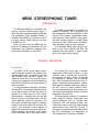
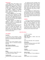
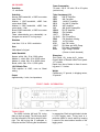
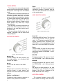
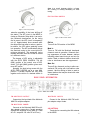
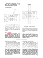
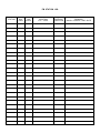
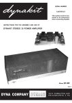
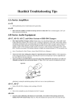
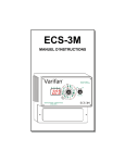
STEREO
TUNER
MR66
INTRODUCTION
1
TECHNICAL DESCRIPTION
1
FRONT PANEL INFORMATION
3
BACK PANEL INFORMATION
5
INSTALLATION
CONNECTING
Monophonic FM and AM
Stereophonic FM and AM
Stereophonic FM Multiplex
Remote Amplifiers
Off-The-Air Tape Recording
Antenna Connections
TABLE OF CONTENTS
OPERATING INSTRUCTIONS
Monophonic AM Reception
Monophonic FM Reception
Stereophonic FM-AM Reception
Stereophonic FM Multiplex Reception
ADJUSTMENTS
Muting Threshold
AM Signal Strength Indicator
FM Tuning Meter
AM and FM Output Levels
Dial Panel Light
GUARANTEE
6
8
8
9
9
9
9
9
11
11
11
12
12
12
12
12
13
13
14
14
MR66
MR66 STEREOPHONIC TUNER
INTRODUCTION
The Mclntosh MR66 is a precision engineered, sensitive AM-FM stereo tuner. It
offers the finest possible reception of AM and
FM broadcasts. Every desirable feature is
included on the MR66. It is perfect for use in
a stereo system where nothing less than
THE BEST will do.
Once you have used the MR66 and enjoyed its outstanding performance, you will
understand why Mclntosh products have
earned their reputation as THE BEST.
The MR66 is quite flexible in operation. It
receives monophonic FM, monophonic AM
and stereophonic AM-FM broadcasts. It also
receives FM multiplex stereophonic broadcasts with the simple addition of the Mclntosh MA6 multiplex adapter. The MR66 front
panel control and switch facilities provide for
every desirable mode of tuner operation.
Your Mclntosh MR66 tuner will give you
years of the finest possible AM and FM
reception and will become a highly valued
part of your home music system.
TECHNICAL DESCRIPTION
FM SECTION
The MR66 FM RF tuning section uses a
special cascode amplifier that amplifies the
weakest signals and yet maintains low noise
and freedom from spurious signals. An
additional tuned RF circuit combined with a
4 gang tuning capacitor contributes greatly to
the excellent selectivity and high rejection of
spurious signals.
A newly developed Automatic Frequency
Control (AFC) circuit greatly simplifies tuning.
As the tuning knob is moved, the tuner responds as if there were no AFC action.
Approximately 3 seconds after the dial has
come to rest on a particular station, the AFC
circuit gradually comes into operation. The
AFC action automatically brings the electrical
tuning to the correct point for minimum distortion. This automatic tuning repeats its
action each time the tuning dial is moved to a
different station. The amount of AFC action
is fully adjustable with a front panel control.
The unique AFC circuit uses a variablecapacitance silicon diode in place of a conventional tube to improve the over-all AFC
performance. The silicon diode is unaffected
by temperature changes, has no warmup
drift, and eliminates tube filament hum. A
special temperature-compensated narrowband detector supplies operating signals to
the AFC circuit to insure positive action.
The narrow-band detector also operates the
FM tuning meter amplifier and the ultrasonic
interstation muting circuit.
Three flat-topped response IF amplifiers
reject adjacent channel interference and
provide adequate gain to operate both
limiters on even the weakest signals. Two
limiters are used to insure the best possible
signal-to-noise ratio. Both the RF and IF
circuits are completely shielded and exceed
the FCC requirements for suppression of
FM oscillator and IF frequency radiation.
1
AM SECTION
The MR66 delivers AM reception of the
highest possible quality. Four different AM
bandwidth/frequency response settings are
available. The NARROW setting provides
excellent selectivity and high noise rejection
for the weaker and more distant stations.
The MEDIUM 1, MEDIUM 2 and BROAD
settings provide progressively wider frequency response for receiving the closer
more powerful stations.
In all but the BROAD setting a very sharplytuned whistle filter eliminates the 10KC
interference caused by adjacent-channel station carriers. This highly-selective filter reduces the 10KC interference 60db (decibels)
below normal program level with no effect on
other audio frequencies.
Local AM reception at the BROAD and
MEDIUM 2 settings is of unusually high
fidelity and limited only by the quality of the
actual broadcast signal itself.
A double-tuned circuit at the input of the
RF amplifier increases selectivity while retaining the excellent AM bandwidth. The
antenna coils are connected with a rear
panel switch to allow perfect matching of a
convenient short loop antenna or a conventional long lead antenna.
An amplified automatic VOLUME control
circuit maintains uniform volume output over
a wide range of station signal strengths.
Powerful local stations, as well as weak or
distant stations, are reproduced at an almost
equal volume level. The need for constant
volume adjustment during tuning is therefore eliminated.
Two IF amplifiers are coupled through a
low-distortion detector into a two-stage feedback amplifier. The output is low-impedance
and approximately equal in level to the FM
output. Level controls on the rear panel allow
you to exactly match the AM and FM output
volume levels.
GENERAL
A new type of mechanical tuning assembly
gives the MR66 extremely smooth flywheel
tuning. The tuning capacitors are driven
directly; the tuning capacitors, in turn, drive
the dial pointers. Backlash is practically
eliminated with this method of design.
A teflon-lined pointer carriage and nylon
pulleys reduce friction and wear to give an
unusually smooth and quiet dial action.
SPECIFICATIONS
FM CHANNEL
with AFC in operation.
Sensitivity
3¼ microvolts at 100% modulation ( ± 75KC
deviation) for less than 3% total noise and
distortion in accordance with IHFM standards.
Image Rejection
Better than 80db at 90MC; better than
70db at 105MC.
Distortion
Less than 0.8% at 100% modulation (±75KC
deviation), above 10 microvolts at antenna
terminals.
Audio Frequency Response
Within 2db from 20 to 20,000 cycles.
Hum
Better than 65db below 100% modulation.
IF Amplifiers
Three (not including two limiters) with 200KC
bandwidth, flat-top response.
RF Amplifier
Cascode
Capture Ratio
1 to 0.7
2
Radiation
Substantially below FCC requirements.
Muting
IF injected ultrasonic muting; 60db or more
noise reduction between stations.
Antenna Inputs
300 ohms balanced; 75 ohms unbalanced.
Oscillator Drift
Less than 25KC with AFC disabled; negligible
Output
Approximately 4 volts, low impedance.
AM CHANNEL
Power Consumption
75 watts, 105 to 125 volts, 50 to 60 cycles,
(entire tuner).
Sensitivity
1.5 microvolts.
Selectivity
Narrow; 4KC bandwidth, ± 10KC from center
down 53db.
Medium 1; 13KC bandwidth, ±10KC from
center down 20db.
Medium 2; 23KC bandwidth, ±10KC from
center down 1.5db.
Broad; 23KC bandwidth, ± 10KC from center
down 1.5db.
These characteristics are substantially unchanged over entire RF tuning range.
Distortion
Less than 1½% at 100% modulation.
Hum
50db below full signal.
Audio Bandwidth
Narrow; within 3db, 20 to 2,000 cycles.
Medium 1; within 3db, 20 to 6,500 cycles.
Medium 2; within 3db, 20 to 8,000 cycles.
Broad; within 3db, 20 to 11,500 cycles.
10KC Whistle Filter
70db rejection at 10KC; none on Broad
setting.
Output
Tube Complement (18)
6BA6
AM RF Amplifier
6BE6
AM Converter
6BA6
1st AM IF Amplifier
6BY8
2nd AM IF Amplifier
6BY8
AGC Amplifier
6U8
AM Audio Preamplifier
6BN4A
FM RF Amplifier
6BN4A
FM Oscillator
12AT7
FM Mixer
(3) 6AU6 FM IF Amplifiers
6BN8
FM Ultrasonic Muting
6AU6
1st FM Limiter
6CS6
2nd FM Limiter
12AU7
FM Meter and AGC Clamp
6U8
FM Audio Preamplifier
6BW4
High Voltage Rectifier
(10mmu to both channels)
Dimensions
Front Panel: 155/8 inches by 51/8 inches.
Overall depth of chassis behind front panel:
123/16 inches.
Depth from face of knobs to face of mounting panel: 1¼ inches.
Weight
Chassis-only, 27 pounds; in shipping carton,
32 pounds.
Approximately 4 volts, low impedance,
FRONT PANEL INFORMATION
Figure 1. MR66 Front Panel.
TUNING DIALS
The MR66 includes AM and FM tuning
dials on the front panel. The AM tuning knob
is at the left and the FM tuning knob is at the
right. The AM tuning dial is calibrated in
kilocycles and the FM tuning dial is calibrated
in megacycles. Each tuning dial also includes
a 0-100 logging scale. Tuning back to a
particular station is much easier by keeping
a record of the exact station location on the
logging scale.
3
TUNING METERS
Two tuning meters are included in the dial
panel. At the left is the AM SIGNAL STRENGTH
tuning meter. At the right is the FM TUNING
meter.
An AM station is correctly tuned when the
AM signal strength meter pointer indicates
maximum right-hand deflection. The actual
amount of meter pointer deflection indicates
the relative signal strength of each particular
station. Strong local stations will cause
almost full meter deflection. Weaker or more
distant stations may cause only a slight
meter deflection.
An FM station is correctly tuned when the
pointer of the FM tuning meter comes to rest
anywhere in the small black center area of
the meter scale.
The zero settings of both meters can be
adjusted if necessary. See the section titled
"ADJUSTMENTS."
AM FUNCTION SWITCH
Broad
Widest possible AM frequency response for
high-fideiity reception of powerful local stations. The 10KC whistle filter is not operative
at this switch setting.
MODE SELECTOR SWITCH
Figure 3. Mode Selector Switch.
Power Off
Turns off the MR66 AC power. The AC outlet
on the back panel also turns off with this
switch. If a TV antenna is used for FM in the
manner described under "ANTENNA CONNECTIONS," it will automatically be switched
back to the TV set in the POWER OFF position.
Stereo
Turns the MR66 AC power ON and provides
simultaneous AM and FM signals at the back
panel jacks marked STEREO-MON 1 and 2,
respectively.
Figure 2. AM Function Switch.
Multiplex FM
Provides multiplex FM stereo reception with
the simple addition of a Mclntosh MA6
multiplex FM adapter.
AM Out
Turns off the AM section of the MR66.
Narrow
Sharpest and most selective AM tuning for
receiving distant or weak stations with
minimum noise and interference from other
stations.
Medium 1 and Medium 2
Progressively wider frequency response for
closer or more powerful local stations.
4
MON FM
Provides monophonic FM signals at "both"
the STEREO-MON 1 and 2 back panel jacks.
MON AM
Provides monophonic AM signals at "both"
the STEREO-MON 1 and 2 back panel jacks.
Note:
AM signals are always present at the back
pane! AM jack, and FM signals are always
present at the FM jack, regardless of the
MODE SELECTOR switch settings.
AUTO FREQ CONTROL
The automatic frequency control (AFC)
circuit makes FM tuning easier and elimi-
close to a much stronger station, a lower
AFC setting is usually necessary for best
tuning.
FM FUNCTION SWITCH
Figure 4. Auto Freq Control.
nates the possibility of the tuner drifting off
the station. The AFC circuit in the MR66 includes an Electronic Delay which is an exclusive Mclntosh development. As the tuning
dial is moved, the AFC circuit is temporarily
cut off. Approximately three seconds after
the dial pointer has come to rest on a particular station, the AFC action gradually comes
into operation. The AFC automatically brings
the electrical tuning to the correct point for
minimum distortion. This automatic tuning
repeats itself each time the FM dial is moved
to a different station.
The degree of AFC action is adjustable
with the AUTO FREQ CONTROL. Full left
(MIN) position of the control cuts off AFC
action. Full right (MAX) position gives maximum AFC action.
Normally, the best tuning occurs with the
AUTO FREQ CONTROL set at or near MAX
position. If several stations are very close
together on the dial or if a desired station is
Figure 5. FM Function Switch.
FM Out
Turns off the FM section of the MR66.
Mute In
Turns on FM with the Mclntosh developed
ultrasonic mute-in operation. Ultrasonic muting suppresses all noise between stations
including noises heard tuning in and out of a
station. Weak or distant stations mixed with
noise or interference are also suppressed.
Mute Out
Turns off the ultrasonic muting to allow conventional FM tuning with inter-station noise
present. Use this setting to listen to weak or
distant stations that may be mixed with noise
or interference.
BACK PANEL INFORMATION
Figure 6- MR66 Back Panel.
FM MULTIPLEX OUTPUT
MULTIPLEX INPUTS
Connects to the input lead of the Mclntosh
MA6 FM multiplex adapter.
Connect to the Mclntosh MA6 FM multiplex adapter output leads.
FM MULTIPLEX POWER
Connects to the Mclntosh MA6 FM multiplex adapter power plug. Correct operating
voltages are supplied for the MA6 (6.3 volts
AC at 1 amp and 120 volts DC at 25 ma.)
AM ANTENNA
Terminals for connecting the AM antenna
to the MR66.
5
ANT LOOP SWITCH
Adjusts the MR66 circuit to match the
particular type of AM antenna used. ANT
position is for a conventional antenna,
usually of the outdoor type, from 50 to 150
feet in length. LOOP position is for the short
loop antenna supplied with the MR66.
LAMPS SWITCH
Provides bright (HI) or dim (LO) front
panel lighting.
AC OUTLET
Provides 117 volt AC power up to 350
watts maximum for additional equipment
such as turntables or other tuners. This outlet is not fused and turns on and off with the
front panel MODE SELECTOR switch.
the MODE SELECTOR turns the MR66 ON.
The antenna is switched back to the TV set
when the MODE SELECTOR is turned to
POWER OFF.
STEREO-MON OUTPUTS
1 and 2 output jacks supply tuner signals
of the correct value to connect to tuner inputs
or auxiliary inputs of a control preamplifier.
The front panel MODE SELECTOR switch provides stereo AM-FM at jacks 1 and 2, respectively; monophonic FM at "both" jacks
1 and 2; or monophonic AM at "both" jacks
1 and 2.
AM FM OUTPUTS
FM ANT
AM signals are present at the AM jack and
FM signals are present at the FM jack at all
times the tuner is operating, regardless of
the MODE SELECTOR switch setting. The
AM function switch and the FM function
switch affect the signals at these output
jacks. Use these jacks to connect the tuner
to remote amplifiers, apart from the main
sound system.
Terminals for connecting an FM antenna
to the MR66.
AM OUTPUT LEVEL CONTROL
TO TV SET
Adjusts the volume level of the AM output.
See section titled "ADJUSTMENTS."
FUSE
1 amp Slo-Blo type fuse to protect the
tuner circuit. This fuse does not operate on
the AC outlet.
Terminals for connecting TV set antenna
leads when a VHF TV antenna is used for
both the MR66 and the TV set. The antenna
is automatically switched to the MR66 when
FM OUTPUT LEVEL CONTROL
Adjusts the volume level of the FM output. See section titled "ADJUSTMENTS."
INSTALLATION
The Mclntosh MR66 tuner may be installed on a table, on a shelf, in a custom
built-in cabinet or in a professional equipment rack. For best appearance in an open
installation, it is suggested that you mount
the MR66 in the attractive Mclntosh Model
L66 finished wood cabinet.
The MR66 may be mounted in panels up
to 1 inch in thickness. If the panel is at least
¼ inch in thickness, the tuner will be adequately supported by the four front panel
mounting screws. In cases where the front
panel may be thin or flexible, a shelf is necessary to support the weight of the tuner. A
shelf is not required when the MR66 is
mounted in a metal rack panel.
6
An MR66 cabinet installation should provide at least 13% inches behind the mounting panel for clearance of leads and connectors. Allow inside dimensions of at least
16½ inches in width and 5 inches in height
for adequate air circulation. The back panel
of the MR66 cabinet should be left as open as
possible for best ventilation. Avoid mounting
the tuner directly over a power amplifier. The
heat from the amplifier output tubes may
affect the precision tuner calibration. Adequate ventilation will insure your tuner a long
and trouble-free life.
CUTTING THE FRONT PANEL
The PANEL CUTOUT TEMPLATE supplied
with your tuner is a full size layout of the front
panel cutout and mounting holes. The template is positioned accurately on the cabinet
front panel by drilling two locating holes
through from the backside of the panel. All
measurements for panel cutout location are
made on the backside of the panel. One of
the two end mounting strips supplied with
the tuner (3½ inches by ½ inch) makes a
convenient measuring tool for determining
the exact positions of the locating holes.
Determine the exact center of the proposed panel cutout area. Scribe a vertical
line at the center, from the top surface of the
mounting shelf to the top of the panel as
shown in "A" of Figure 7. Using one of the
mounting strips as a measuring tool, scribe a
horizontal line 3½ inches above the top
surface of the mounting shelf as shown in
" B " of Figure 7. Again using the mounting
strip, mark a point on the horizontal line 3½
inches to the left of the center line. Mark a
second point 3½ inches to the right of the
center line. These two points should be 7
inches apart, 3½ inches above the mounting
shelf and 3½ inches to each side of the
vertical center line. See "C"of Figure 7. Drill
a 3/16 inch diameter hole through the back of
the panel at each of the two points. Make
certain that you hold the drill perpendicular
to the panel so the holes will be accurately
located on the front side of the panel.
VERTICAL CENTER LINE
Positions " A " to " C " show the location of the
vertical center line, the use of the measuring
tool (mounting strip) to locate the horizontal
center line, and how to measure off the two
points to the right and left of the vertical center
line.
Using the previously drilled locating holes
for correct alignment, carefully position the
cutout template on the front panel.
Scribe the rectangular cutout on the front
panel and mark the positions of the six
mounting holes. Drill the six 3/16 inch diameter
mounting holes before cutting the panel
opening. Next cut the main panel opening. It
is important that the cutout be just within the
heavy black lines on the template.
SHELF MOUNTING
Locate the exact center of the proposed
shelf area and scribe a line from the front to
the back of the shelf. The SHELF CUTOUT
TEMPLATE is marked for front panel thickness from ¼ inch to 1 inch. Fold the template
on the line that corresponds to the thickness
of the particular panel being used. Place the
folded template on the shelf, butted against
the backside of the front panel. Match the
center line on the template to the scribed
center line on the shelf. The shelf center line
should also exactly meet the vertical center
line used to make the front panel cutout.
Mark the positions of the four ¼ inch diameter mounting holes. Scribe the rectangular
cutout for the ventilating hole. Drill the four
¼ inch diameter mounting holes and cut out
the rectangular ventilating hole.
INSTALLING THE MR66
Remove the four 10-32 x ¾ inch screws
holding the MR66 to the shipping board.
Save these screws since you will need them if
your cabinet shelf is ½ inch or 5/8 inch thick.
Remove the four plastic feet from the bottom
of the tuner.
The mounting hardware package includes
four 6-32 flat head screws and eight 6-32
round head screws. Two of the flat head
screws of the proper length are used to
attach the mounting strips to the cabinet
panel. Four of the round head screws of the
proper length are used to attach the tuner to
the mounting strips and the cabinet panel.
The 6-32 x ½ inch screws are used with
panels under 3/8 inch thickness. The 6-32 x
1¼ inch screws are used with panels from
3
/8 inch to 1 inch thickness.
Figure 7. Front Panel Cutout Measurements.
7
The edge of the strip with the clips must
face toward the panel opening. Line up the
mounting strips on each side of the panel
cutout so the holes in the strips are in line
with the holes in the panel. (See Figure 8.)
Install the proper length flat head screws
through the front panel and into the center
hole of each strip. Drive the screws in so the
flat heads are flush with the panel. If necessary, countersink the two center holes.
ness or less. Use the 10-32 x 1 inch screws if
the shelf is ¾ inch or 7/8 inch thickness.
Secure the chassis with the proper length
10-32 screws by inserting them up through
the holes in the shelf and into the threaded
holes in the tuner chassis bottom. Tighten
the 10-32 screws after you have first tightened the front panel screws.
IMPORTANT
Use of the wrong length 10-32
screws may cause electrical shorting in the tuner circuits.
Attach the two metal panel end caps
(packed with the tuner) on each end of the
tuner panel by sliding onto the pins. (See
Figure 9.) The end caps are held by spring
tension and can easily be removed if the
tuner is to be taken out of the cabinet.
Figure 8. Securing The Mounting Strip To The Front Panel.
Carefully insert the tuner through the
front panel opening so it rests on the supporting shelf. Insert the proper length round
head screws into the four holes in the mounting flanges on each end of the tuner panel.
Drive the screws in through the panel and into
the threaded clips on the mounting strips.
Do not tighten these screws yet.
If the cabinet is fixed and will not be
moved about, it is not necessary to secure
the tuner chassis to the shelf. If the cabinet
is to be moved about, it is recommended
that the tuner chassis be secured to the
shelf in the following manner.
Tighten the four screws holding the tuner
to the front panel. The four 10-32 x ¾ inch
screws used in shipping the tuner are also
used to mount it to a shelf of ½ inch or 5/8
inch thickness. Use the 10-32 x ½ inch
screws if the mounting shelf is 3/8 inch thick-
PUSH ON
Figure 9. Fitting End Caps To Tuner Panel.
MOUNTING IN THE L66 CABINET
The Mclntosh L66 cabinet is supplied
with complete instructions and all necessary
hardware for installing the MR66 tuner. The
dimensions of the L66 cabinet are 169/16
inches wide by 611/16 inches high including
mounting feet by 13¾ inches deep including
tuner front panel and control knobs.
CONNECTING
MONOPHONIC FM AND AM
Connect one end of a shielded cable supplied with the tuner to either the STEREOMON 1 or 2 output jack on the back panel of
8
the MR66. Connect the other end of the
cable to a high-level auxiliary or tuner input of
a monophonic preamplifier. The MR66 has
sufficient output level to be connected
directly to a power amplifier if desired.
Since the MR66 does not include a front
panel volume control, all volume adjustments must be made at the preamplifier.
The MR66 rear panel output level controls
provide means for setting and balancing the
volume levels of the AM and FM outputs.
AM monophonic and FM monophonic programs appear at both STEREO MON 1 and
2 jacks, depending on whether the MODE
SELECTOR switch is set to MON AM or
MON FM.
STEREOPHONIC FM AND AM
Connect one end of a shielded cable supplied with the MR66 to the STEREO MON
1 output jack on the back panel of the MR66.
Connect the other end of this cable to the
left-channel high-level auxiliary or tuner input of a stereophonic control preamplifier.
Connect one end of another shielded cable
from the STEREO MON 2 output jack to the
right-channel high-level auxiliary or tuner
input of the stereophonic control preamplifier. Two separate monophonic preamplifiers may also be used for the separate
channels in a similar manner. :Channe!s 1
and 2 refer to left and right respectively.)
AM-FM stereophonic programs will be
heard with the AM through the left channel
and the FM through the right channel. Monophonic AM and monophonic FM programs
will also be heard with these connections
depending on the MR66 MODE SELECTOR
switch setting. Monophonic programs will
appear through both channels simultaneously.
STEREOPHONIC FM MULTIPLEX
For reception of FM Multiplex Stereo, connect the MR66 tuner the same as for stereophonic FM-AM. Then connect the Mclntosh
MA6 Multiplex Adapter to the MR66 as
follows.
Connect the MA6 Multiplex Adapter power
plug to the FM multiplex power socket on the
MR66 back panel. Connect a 24-inch shielded
cable supplied with the MA6 adapter from
the adapter INPUT jack to the FM MULTIPLEX OUTPUT jack on the MR66 back panel.
Connect a 24-inch shielded cable from the
LEFT OUTPUT jack on the MA6 adapter to
the MULTIPLEX INPUT 1 on the MR66 back
panel. Connect a 24-inch shielded cable from
the RIGHT OUTPUT jack on the MA6 adapter
to the MULTIPLEX INPUT 2 on the MR66
rear panel. The numbers 1 and 2 on the
MR66 back panel refer to left and right
channels respectively.
REMOTE AMPLIFIERS
The AM and FM OUTPUT jacks on the
MR66 back panel provide separate AM and
FM signals at all times, regardless of the
MR66 MODE SELECTOR switch setting.
These jacks may be connected to external
power amplifiers for purposes of feeding
AM and FM programs to other speaker locations apart from the main sound system.
OFF-THE-AIR TAPE RECORDING
Tape recorders or tape decks with recordplayback preamplifiers are normally connected to the Tape Output jacks on the control preamplifier. Any FM or AM program
coming from the tuner into the preamplifier
can then be recorded on tape. You may also
connect the AM and FM or STEREO-MON
jacks directly to the recorder inputs if desired.
AM ANTENNAS
INDOOR LOOP
For most local and moderately distant AM
reception the convenient loop antenna wire
supplied with the MR66 may be used. Remove the metal link between the AM ANTENNA terminals marked LO and GND on
the MR66 back panel. Connect one end of
the loop to the HI terminal. Connect the other
end of the loop to the LO terminal. Set the
AM ANTENNA slide switch on the MR66 back
panel to the LOOP position. (See Figure 11.)
Figure 11. Indoor Loop Antenna Connections.
9
The AM loop may be conveniently tacked
behind the stereo equipment cabinet, or
stretched along the floor or baseboard. The
loop should be spaced as wide apart as
possible.
3 0 0 OHM INDOOR
DIPOLE FM ANTENNA
AM OUTDOOR ANTENNA
Figure 13. Connection For
300 Ohm Indoor Dipole FM Antenna.
Figure 12. AM Outdoor Antenna.
For best long distance AM reception, use a
copper antenna wire 50 to 150 feet in length.
Suspend the wire in a straight line as high as
possible. Attach the wire at each end with
suitable glass or ceramic insulators. Connect
a lead-in wire at any convenient point on the
antenna. (See Figure 12.) It is recommended
that a lightning arrester be used with an outdoor AM antenna. The arrester should be
well grounded to a suitable water pipe or
copper or aluminum rod sunk into the ground.
Connect the lead-in wire to the HI terminal on the AM ANTENNA terminal strip on
the MR66 back panel. Leave the metal link in
place between the LO and GND terminals.
Set the AM ANTENNA Slide Switch on the
MR66 back panel to the ANT position.
INDOOR FLEXIBLE FM DIPOLE
The convenient flexible indoor dipole
(300 ohm) antenna is supplied with the MR66
tuner. This antenna is suitable for FM reception in urban or high-intensity signal areas.
Connect the two leads of the dipole antenna to the two terminals marked FM ANT
on the MR66 back panel. (See. Figure 12.)
The flexibility of the thin flat wire allows the
dipole to be easily located behind the equipment enclosure or in any convenient position
near the tuner. Open the dipole into a "T"
and extend the arms as straight as possible.
The dipole antenna is somewhat directional
10
and may have to be positioned in a particular
location for best reception of the desired
stations. The dipole may be carefully tacked
or taped into position.
IMPORTANT
Keep the dipole away from large
metal objects or surfaces since
they may interfere with the efficiency of the antenna.
FM OUTDOOR ANTENNA
An outdoor FM antenna is always recommended for best FM reception under all conditions. In fringe or outlying areas, a highly
directional FM antenna used in conjunction
with a rotator will give the finest possible FM
reception. Rotate the antenna until it points
toward the station or receives the best possible signal.
Figure 14. Connection For 300 Ohm Outdoor FM Antenna.
Connect the two wires of the 300 ohm
lead-in from the external antenna to the
MR66 back panel FM ANT terminals.
FROM VHF TV
ANTENNA
75 OHM ANTENNA
Figure 15. Connection For 75 Ohm Coaxial Antenna.
TO TV SET
An unbalanced 75 ohm FM antenna may
also be used with the MR66. Connect the
center lead of the coaxial lead-in cable to the
right hand FM ANT terminal. Connect the
shield of the coaxial cable to the ground
screw next to the right of this same FM ANT
terminal.
Figure 16. VHF TV Antenna Connections.
Connect a length of 300 ohm flat lead-in wire
from the TO TV SET terminals on the MR66
back panel to the antenna terminals of the
TV set.
VHF-TV ANTENNA
A conventional VHF TV antenna of the
type also suitable for FM may be used with
the MR66. Connect the two leads from the
300 ohm TV antenna lead-in wire to the two
FM ANT terminals on the MR66 back panel.
The MR66 MODE SELECTOR switch automatically switches the VHF TV antenna to the
MR66 in any of the " o n " positions. The
antenna is switched back to the TV set in the
POWER OFF position.
OPERATING INSTRUCTIONS
MONOPHONIC AM RECEPTION
MONOPHONIC FM RECEPTION
Turn the MR66 MODE SELECTOR switch
to MON AM. Turn the FM FUNCTION switch
to FM OUT. Turn the AM FUNCTION switch
to any of the four bandwidth settings. It is
usually easiest to tune at the NARROW or
MEDIUM 1 position. After a warm up time of
approximately 30 seconds, turn the AM
tuning dial to the desired station. Depending
on the quality of the AM signal, select the
best possible bandwidth setting. (See the
section titled "AM FUNCTION SWITCH.":
The AM Signal Strength meter will indicate
the relative strength of the particular AM
station being received.
Turn the MODE SELECTOR switch to
MON FM. Turn the AM FUNCTION switch to
AM OUT. Turn the FM FUNCTION switch to
MUTE IN. Set the AUTO FREQ CONTROL to
any position between MIN and MAX. (See the
section titled "AUTO FREQ CONTROL.")
After a warmup time of approximately 30
seconds, turn the FM tuning dial to the desired station. The correct FM tuning point is
reached when the FM TUNING meter pointer
comes to rest anywhere in the center black
area of the meter scale. While tuning across
the dial you may notice movement of the
tuning meter, yet don't hear a station. This is
11
caused by a station so weak or distant that it
does not over-ride the background noise.
With ultrasonic muting in operation a noisy
station of this type is automatically rejected.
To hear these weaker or distant stations, turn
the FM FUNCTION switch to MUTE OUT.
Usually the listening quality of a station of
this type will be rather poor due to the weak
signal and background noise. (See section
titled "MUTING ADJUSTMENTS.")
If two FM stations are very close together
on the dial, the AFC action may tend to capture and hold the stronger of the two stations. Turn the AUTO FREQ CONTROL to the
left (counterclockwise) to reduce AFC in
order to tune in the weaker station. The
quality of the FM program is unaffected by
the setting of the AUTO FREQ CONTROL.
(See section titled "AUTO FREQ CONTROL.")
STEREOPHONIC AM-FM RECEPTION
Turn the AM FUNCTION switch to BROAD,
the MODE SELECTOR switch to STEREO, and
the FM FUNCTION switch to MUTE IN. Set
the AUTO FREQ CONTROL to any setting
between MIN and MAX. Allow a warmup time
of approximately 30 seconds.
Tune the AM dial to the AM station broadcasting one channel of the stereophonic
program. Then tune the FM dial to the FM
station broadcasting the other channel of the
same stereophonic program.
If 10KC squeal interference is present in
the AM channel, turn the AM FUNCTION
switch to the MED 2 position. This places the
10KC filter in operation.
STEREOPHONIC FM MULTIPLEX
RECEPTION
The Mclntosh MA6 FM Multiplex Adapter
must be properly installed in the MR66 in
order to receive FM Multiplex Stereophonic
programs. (See Section under "CONNECTING" titled "STEREOPHONIC FM MULTIPLEX.")
Turn the AM FUNCTION switch to MULTIPLEX FM, the MODE SELECTOR switch to
STEREO and the FM FUNCTION switch to
MUTE IN. Set the AUTO FREQ CONTROL to
any position between MIN and MAX. Tune
the FM dial to the station broadcasting FM
Multiplex Stereo. Satisfactory FM Multiplex
Stereo reception requires approximately 10
times as much signal from the antenna compared to equivalent FM monophonic reception. Monophonic installations that were
satisfactory with an indoor FM antenna may
require an outside or directional FM antenna
for equivalent FM Multiplex reception.
ADJUSTMENTS
MUTING THRESHOLD
The MR66 ultrasonic muting circuit suppresses all noise between stations. It also
suppresses all weaker stations not strong
enough to over-ride the background noise.
The muting threshold setting determines
the strength of the signal which can be
heard with muting in operation. The muting
threshold is carefully adjusted to optimum at
the factory using precision test instruments.
Casual adjustment of the muting threshold
is not recommended.
If it is found necessary to adjust the
muting threshold, use the SQUELCH ADJ
control on top of the MR66 chassis. Turn the
SQUELCH ADJ control to the RIGHT (clockwise) to lower the muting threshold. This
allows weaker, noisier stations to be heard at
12
the MUTE IN setting. Turn the SQUELCH
ADJ control to the LEFT (counterclockwise) to
raise the muting threshold. This allows only
the more powerful stations to be heard at
the MUTE IN setting.
AM SIGNAL STRENGTH INDICATOR
The AM Signal Strength indicator pointer
normally should rest on the zero scale marking with AM operating but no station tuned in.
To adjust, turn the AM FUNCTION switch
to BROAD and the MODE SELECTOR switch
to MON AM. Turn the AM tuning dial until the
pointer is not on or near a station. Remove
the AM antenna from the back panel antenna
terminals. (This eliminates any noise or
interference which may cause a slight meter
deflection.) Rotate the red AM MTR ADJ
thumb wheel control (under the left dial
panel end cap) until the meter pointer is
centered on the zero scale marking.(Tuner
Serial Nos. 1N001 to 1N961 have recessed
screwdriver-adjust AM meter control near
back of tuner chassis.)
In areas where noise or interference is
high, the meter may move above the zero
position when the AM antenna is reconnected to the back panel terminals. This is
normal and does not affect the meter operation.
FM TUNING METER
Turn the FM FUNCTION switch to FM
OUT position. (The meter pilot lamp turns off
but the circuit is still on.) All other controls
and switches may be in any position. Allow
the tuner to operate for approximately
5 minutes. The FM tuning meter pointer
should rest in the center of the black scale.
To adjust, rotate the red FM MTR ADJ
thumb wheel control (under right dial panel
end cap) until the meter pointer rests in the
center of the black scale. (Tuner Serial
Nos. 1N001 to 1N961 have a screwdriveradjust FM meter control near back of tuner
chassis.)
AM AND FM OUTPUT LEVELS
Adjust each control until the MR66 AM
and FM output volume levels are equal to
each other. They should also be equal to the
volume levels of other signal sources (such
as phono) connected to the control preamplifier. You can now switch the preamplifier from the MR66 to other program
sources without need for readjusting the
main preamplifier volume control.
DIAL PANEL LIGHTS
Adjust the brightness of the dial panel
lights by means of the lamp slide switch on
the MR66 back panel. Set the switch to HI
position for maximum dial light. Set the
switch to LO for a dimmer light and extended
lamp life.
13
Your Mclntosh MR66 tuner will give you many years of pleasant and satisfactory performance. If you have any questions concerning the operation or maintenance of this tuner, please contact
CUSTOMER SERVICE
McINTOSH LABORATORY INC.
2 CHAMBERS STREET
BINGHAMTON, NEW YORK
Our telephone number is 723-5491.
The direct dial area code is 607.
GUARANTEE
Mclntosh Laboratory, Inc. guarantees this equipment to perform as advertised. We also guarantee the mechanical and
electrical workmanship and components of this equipment to be
free of defects for a period of 90 days from date of purchase.
This guarantee does not extend to components damaged by
improper use nor does it extend to damage incurred during
transportation to and from Mclntosh Laboratory, Inc.
In Canada: Manufactured under license by:
McCurdy Radio Industries, Ltd.
22 Front Street West
Toronto, Canada
14
AM STATION LOG
STATION
DIAL
FREQ.
LOG
SCALE
LOCATION
CITY, STATE
ANTENNA
DIRECTION
REMARKS
MONO—STEREO-TIME—DATE
FM STATION LOG
STATION
DIAL
FREQ.
LOG
SCALE
LOCATION
CITY, STATE
ANTENNA
DIRECTION
REMARKS
MONO—STEREO—TIME—DATE
LABORATORY INC.
2 C H A M B E R S STREET, B I N G H A M T O N , N. Y.
M a d e in U.S.A.
Phone — A r e a Code 607-723-5491
1M-AA107-236
Printed in U.S.A.