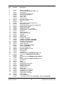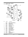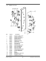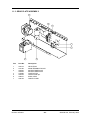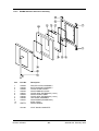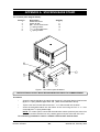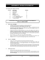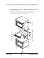
1
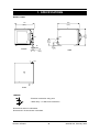
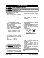
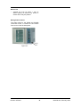
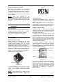
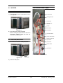
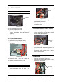
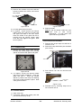
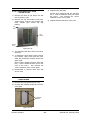
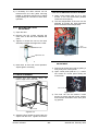
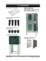
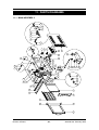
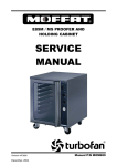
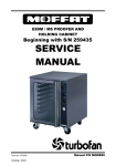
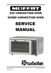
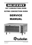
E32MS CONVECTION
OVEN
SERVICE MANUAL
Beginning with S/N 240090
Revision 3/F3587
February, 2005
Manual P/N M0ME32MAX
WARNING: ALL INSTALLATION AND SERVICE REPAIR WORK MUST BE CARRIED
OUT BY QUALIFIED PERSONS ONLY.
Revision 3/F3587
-2-
© Moffat Ltd, February 2005
CONTENTS
This manual is designed to take a more in depth look at the E32M and E32MS convection ovens
for the purpose of making the units more understandable to service people.
There are settings explained in this manual that should never require to be adjusted, but for
completeness and those special cases where these settings are required to change, this manual
gives a full explanation as to how, and what effects will result.
SECTION
PAGE NO.
1.
SPECIFICATIONS......................................................................................................... 5
2.
INSTALLATION............................................................................................................. 7
3.
OPERATION .................................................................................................................. 10
3.1
3.2
4.
Description of Controls
Explanation of Control System
MAINTENANCE............................................................................................................. 13
4.1
4.2
Cleaning
Routine Procedures
5.
TROUBLE SHOOTING GUIDE ..................................................................................... 15
6.
SERVICE PROCEDURES ............................................................................................. 19
6.1
6.2
6.3
6.4
Fault Diagnosis
Access
Replacement
Adjustment / Calibration
7.
ELECTRICAL SCHEMATICS........................................................................................ 36
8.
ELECTRICAL WIRING DIAGRAMS ............................................................................. 37
9.
SPARE PARTS.............................................................................................................. 38
10.
ACCESSORIES / OPTIONS.......................................................................................... 39
IMPORTANT: MAKING ALTERATIONS MAY VOID WARRANTIES AND APPROVALS.
Revision 3/F3587
-3-
© Moffat Ltd, February 2005
11.
PARTS DIAGRAM ......................................................................................................... 40
11.1
11.2
11.3
11.4
12.
Main Assembly
Control Panel Assembly
Gear Plate Assembly
Door Assembly
SERVICE CONTACTS................................................................................................... 47
APPENDIX A. STACKING BASE STAND............................................................................. 49
APPENDIX B. DOUBLE STACKING KIT .............................................................................. 50
Revision 3/F3587
-4-
© Moffat Ltd, February 2005
1. SPECIFICATIONS
MODEL: E32M
810
(32")
E
50
(2")
FRONT
1
E
120
(4¾")
1
MWS
280
(11")
MWS
70
(2¾")
1
E
670
(26½")
710
(28")
SIDE
MWS
PLAN
LEGEND
- Electrical connection entry point
- Water entry - ¾” BSP hose connection
Dimensions shown in millimetres.
Dimensions in inches shown in brackets.
Revision 3/F3587
-5-
© Moffat Ltd, February 2005
MODEL: E32MS
810
(32")
1
MWS
280
(11")
MWS
E
70
(2¾")
1
E
1
E
120
(4¾")
50
(2")
FRONT
670
(26½")
710
(28")
SIDE
MWS
PLAN
LEGEND
- Electrical connection entry point
- Water entry - ¾” BSP hose connection
Dimensions shown in millimetres.
Dimensions in inches shown in brackets.
Revision 3/F3587
-6-
© Moffat Ltd, February 2005
LOCATION
To ensure correct ventilation for the motor and
controls the following minimum installation
clearances are to be adhered to:
Rear
40mm / 1.5“
Left-hand side
40mm / 1.5”
Right-hand side*
40mm / 1.5”
Top
200mm / 8”
* Fixed installations require at least 500mm
(20”) clearance at the right hand side for
service accessibility.
OVEN INTERNAL DIMENSIONS
Width
Height
Depth
Oven Volume
468 mm / 18.5”
533 mm / 21”
711 mm / 28”
0.18 m³ / 6.3 ft³
OVEN RACK SIZE
Width:
Depth:
460 mm / 18”
660 mm / 26”
No of rack positions:
4
Rack position spacing: 125 mm / 5”
ELECTRICAL SUPPLY SPECIFICATION
OPTIONS
208 V AC 60 Hz, 28.8 A , 6.0 kW@ 208 V
220-240 V AC 60 Hz, 27.8 A, 6.7 kW @ 240 V
208-220 V AC 50 Hz, 28.8 A, 6.0 kW @ 208 V
230-240 V AC 50 Hz, 27.8 A, 6.7 kW @ 240 V
ELECTRICAL CONNECTION WIRE
CONDUCTOR SIZES
Minimum:
4mm² / 16 AWG
WATER SUPPLY CONNECTION
Max Pressure 550 kPa / 5.5 bar / 80 psi
Min Pressure 100 kPa / 1.0 bar / 15 psi
Revision 3/F3587
-7-
© Moffat Ltd, February 2005
2. INSTALLATION
WARNING: THIS APPLIANCE MUST BE GROUNDED.
WARNING: ALL INSTALLATION AND SERVICE REPAIR WORK MUST BE CARRIED
OUT BY QUALIFIED PERSONS ONLY.
Before Connection to Power Supply
•
Remove all packing.
•
Check equipment and parts for damage.
Report any damage immediately to the
carrier and distributor.
•
Remove protective plastic coating from
the side panels.
•
Check that the following parts have been
supplied with your oven:
floor mounting or provided with stands are
adjustable and will require adjusting in
levelling the unit.
•
Electrical Connection
4 x Foot assembly
4 x Oven racks
1 x Water inlet elbow (c/w washer)
•
Report any deficiencies to the distributor
who supplied the oven.
•
Fit the feet to the oven.
•
Check that the available power supply is
correct to that shown on the rating plate
located on the right -hand side panel.
The unit should be positioned such that
the operating panel and oven shelves are
easily reachable for loading and
unloading.
•
Remove right hand side panel to allow
access to the terminal block and strain
relief cable clamp.
•
The cable can be fitted through the small
grommet and held by the cable clamp.
•
Connect
marked.
•
Refit cover panel.
208-220 V AC, 50 Hz, 28.8 A, 6.0 kW
208 V AC, 60 Hz, 28.8 A, 6.0 kW
230-240 V AC, 50 Hz, 27.8 A, 6.7 kW
220-240 V AC, 60 Hz, 27.8 A, 6.7 kW
L1
Phase
BLACK
BLUE
WHITE
GREEN
GREEN/YELLOW
2.1
Water Connection
40mm / 1½”
40mm / 1½”
40mm / 1½”
200mm / 16”
•
A cold water supply should be fitted to the
water inlet (¾” BSP hose connection)
which is located on the rear of the right
hand side of the unit.
•
Alternately, a connection elbow
sealing washer is supplied with this
for direct connection of a ½” ID hose,
is recommended for easy installation
service.
•
Connect water supply - Max inlet pressure
80psi / 550kPa.
•
Turn on water supply to check for leaks.
Position the oven in its working position.
Use a spirit level to ensure oven is level
from side to side and front to back. (If this
is not carried out, uneven cooking could
occur). The feet/legs used with bench/
Revision 3/F3587
as
Ground
Figure
IMPORTANT:
THE OVEN VENT
LOCATED ON THE CABINET TOP
MUST NEVER BE OBSTRUCTED.
•
terminals
BE GROUNDED / EARTHED
* Fixed installations require at least
500mm (20”) clearance at the right
hand side for service accessibility.
•
L2
the
WARNING: THIS APPLIANCE MUST
To ensure correct ventilation for the motor
and controls the following minimum
installation clearances are to be adhered
to:
Rear
Left-hand side
Right-hand side*
Top
to
Neutral
RED
BROWN
BLACK
Location
•
cable
and
unit
and
and
IMPORTANT: MAXIMUM INLET WATER
PRESSURE IS 550 kPa / 80 psi.
-8-
© Moffat Ltd, February 2005
Before Use
•
Operate the oven for about 1 hour at
200°C (400°F) to remove any fumes or
odours which may be present.
Rating Plate Location
The rating plate for the E32M and E32MS
convection ovens is located at the bottom
front corner of the RH side panel.
Figure 2.3
Revision 3/F3587
Rating
Plate
-9-
© Moffat Ltd, February 2005
3. OPERATION
NOTE: A full user’s operation manual is supplied with the product and can be used for further
referencing of installation, operation and service.
3.1 DESCRIPTION OF CONTROLS
1.
Power
1
Depress to switch power on or off (switch
illuminates when power is on).
2.
Thermostat
Temperature range 50 - 320°C (120 - 600°F).
Indicator illuminates when elements are
cycling ON to maintain set temperature.
3.
2
Bake Timer
1 Hour bake timer.
(Indicator illuminates when “time up” (0)
reached, and buzzer sounds).
3
4.
Roast ‘n’ Hold
Depress switch to activate ’Roast ’n’ Hold’
function. (Switch illuminates when ON).
5.
4
Roast Timer
3 Hour roast timer.
(Indicator illuminates when “time up” (0)
reached, and product held at 75°C (167°F).
6.
5
Steam Switch
Push switch to activate water injection.
(Water injects into oven while the button is
depressed).
7.
6
Light Switch
Push switch to activate lights.
7
Revision 3/F3587
-10-
© Moffat Ltd, February 2005
3.2
EXPLANATION OF CONTROL
SYSTEM
The temperature control of this oven is with a
capillary type thermostat which can be set to a
required cooking temperature.
The E32M and E32MS Turbofan convection
ovens feature multi-function operator controls
for which a correct understanding of their
operation is required before carrying out any
service or fault repair work. The control
device functions are explained as follows:
The control panel indicator light above the
thermostat knob cycles On and Off with the
thermostat to indicate when the elements are
on and the oven is heating.
The E32M and E32MS Turbofan convection
ovens have 6.5 kW of electric heating
elements, comprising of a 3 kW inner coil, and
a 3.5 kW outer coil, both of which make up the
element assembly around the oven fan. The
elements are switched on and off by the main
oven
thermostat or hold thermostat via a
four-pole 25 Amp contactor located inside the
control housing.
Only two poles of the
contactor are used, one for each element coil.
Power to the oven thermostat is supplied from
the door microswitch, and will therefore only
switch the elements on if the oven door is
closed.
A power switch on the control panel isolates
power to the controls of the oven. With the
power switch Off all functions of the oven are
inoperable.
With the power switch On (illuminated) power
is directly supplied to the 60 minute bake
timer, steam (water injection) switch, door
microswitch, light switch, and the temperature
control circuit. The oven circulation fan will
operate whenever the power switch is on.
The control panel light switch will turn the
oven lights on when the door is closed. The
oven lights will come on automatically when
the door is open, as this is controlled by the
door microswitch. The oven fan and heating
elements are also controlled by the door
microswitch, and will therefore only operate
when the door is closed.
The circulation fan on the E32M and E32MS
ovens reverses direction every 90 seconds for
a 50Hz supply (every 75 seconds for 60Hz).
Prior to a change of direction the fan motor is
switched off for 10 seconds (8½ seconds for
60Hz) to allow the motor/fan to slow down.
Cycling of the fan motor is controlled by a
continuous cam timer with electric motor. The
timer has two cams and switches which
supply power alternately to one of two motor
supply wires, causing the motor to alternate
direction. During the fan motor slow down
periods, both cam switches are open and
power is not supplied to either of the motor
supply wires. When the oven door is opened
or the power is switched off the cams will
stop. When the oven door is closed or the
power switched back on the cam timer will
resume its cycle from the point where it
stopped.
The 60 minute timer is a mechanical timer and
can therefore be operated with the oven’s
power switch On or Off. However, only with
the oven’s power switch On will the switch
contacts of the 60 minute timer turn on the
time-up buzzer and illuminate the time-up
indicator on the control panel. The buzzer
and time-up indicator provide indication that
the time setting has run down to zero and at
this point will remain On continuously until the
60 minute timer has been manually set back
to the Off (vertical) position. The 60 minute
timer does not control any other part of the
oven’s operating system as this timer is
independent of the temperature control and
heating system.
The fan motor is a split phase continuous
capacitor motor with the capacitor externally
connected across the motor supply leads.
The motor also incorporates an internal
thermal trip switch for overheat protection
which is auto resetting.
The steam (water injection) switch on the
control panel can be operated whenever the
power switch is On. The switch is momentary
like the light switch and when depressed, will
operate the electric solenoid valve at the rear
of the oven and inject water across the
elements and fan from the flat spray (vertical)
nozzle positioned at the rear of the oven
elements. Releasing the steam button will
close the solenoid valve. This feature is used
to instantaneously add steam into the oven.
Revision 3/F3587
The E32M and E32MS Turbofan convection
ovens feature a Roast-and-Hold system which
can be used to automatically set the oven to a
fixed holding temperature at the end of a
timed cooking period. When the Roast-andHold switch is turned On the switch will
illuminate and switch on a hold relay found
-11-
© Moffat Ltd, February 2005
inside the control panel. When the relay is
switched ON a normally closed switch pole on
the relay is opened and the normal power
supply to the oven thermostat is isolated. A
s
e
c
o
n
d
normally open switch pole is closed and this
provides power to the 3 hour roast timer.
The following Troubleshooting Guide should
be used to identify any incorrect oven
operation. On correct identification of the
operating fault the Troubleshooting Guide will
make reference to the corrective action
required, or refer to the Fault Diagnosis
section and/or Service section to assist in
correction of the fault.
If the roast timer is in the Hold (vertical)
position the timer switch contacts will be in
their normally closed position and supply
power directly to the Hold thermostat located
behind the control panel.
The Hold
thermostat is factory set to 75°C (167°F) and
will supply power to the heating elements
through the heating contactor as required to
maintain its preset temperature.
The thermostat heating light will also cycle
On/Off as the Hold thermostat maintains
temperature.
In the Roast-and Hold mode the 3 hour timer
can be set to a selected roasting time. During
this time period the normally open switch
contacts of the timer are closed. The timer
has two change over switches and in this
position one is used to supply power to its
timing motor and the other is used to switch
power directly to the main oven thermostat.
During the 3 hour timer run-down period the
oven temperature will be controlled by the
main oven thermostat to the set temperature
and operate as previously described.
When the 3 hour timer has run down and
reached the Hold position the two switch
contacts change over to their normally closed
position which isolates power from the timer
motor and the oven thermostat.
It also
switches power back to the oven hold
thermostat. At this point the temperature
control is now maintained by the hold
thermostat as previously described.
To
cancel the hold circuit the Roast-and-Hold
switch is turned Off. This turns off the
contactor which removes power from the 3
hour timer and closes the contactor pole on
the contactor that feeds the main oven
thermostat. The Hold indicator light above the
3 Hour timer will illuminate whenever the oven
is operating in hold mode (Roast ‘n Hold
selected, and 3 Hour timer at zero position).
The factory preset hold thermostat can be
adjusted as required to change the holding
temperature if necessary.
Refer Service
section for this procedure.
Revision 3/F3587
-12-
© Moffat Ltd, February 2005
4. MAINTENANCE
WARNING: ALL INSTALLATION AND SERVICE REPAIR WORK MUST BE CARRIED
OUT BY QUALIFIED PERSONS ONLY.
4.1 CLEANING
OVEN SEALS
WARNING: ALWAYS TURN THE
POWER SUPPLY OFF BEFORE
CLEANING.
To remove, hold at their centre point and
pull forward until they unclip. Remove side
seals first, then top and bottom. The seals
may be washed in the sink, but take care not
to cut or damage them. To replace, ensure
that the lip is facing the oven opening. Fit
the top and bottom seals first, then the side
seals.
IMPORTANT: THIS UNIT IS NOT
WATER PROOF.
DO NOT USE A WATER JET SPRAY TO
CLEAN INTERIOR OR EXTERIOR OF
THIS UNIT.
EXTERIOR
OVEN DOOR GLASS
Clean with a good quality stainless steel
cleaning compound. Harsh abrasive cleaners
may damage the surface.
Clean with conventional glass cleaners.
INTERIOR
Ensure that the oven chamber is cool. Do not
use wire brushes, steel wool or other abrasive
materials. Clean the oven regularly with a
good quality oven cleaner. Take care not to
damage the fan or the tube at the right side of
the oven which controls the thermostat.
OVEN RACKS
To remove, slide out to the stop position, raise
the front edge up, and lift out.
SIDE RACKS
To remove, lift front top to disengage and
slide rack forward. To replace, slide top rear
slot in rack onto rear stud, then engage front
keyhole on front stud.
LAMP GLASS
To remove glasses, unscrew anti-clockwise.
To replace, screw in clockwise.
IMPORTANT:
DO NOT
TIGHTEN LAMP GLASS.
Revision 3/F3587
OVER
-13-
© Moffat Ltd, February 2005
4.2 ROUTINE PROCEDURES
PROCEDURE
INTERVAL
DOOR SEALS
Check for deterioration.
12 months
DOOR PIVOT BUSHES
Check for wear.
12 months
DOOR CATCHES
Ensure that catches are adjusted such that the door
closes properly.
12 months
ELEMENT
Check that element resistance is correct to it’s rating
(refer 6.3.15).
12 months
WATER NOZZLE
Check for liming in water nozzle.
12 months
Revision 3/F3587
-14-
© Moffat Ltd, February 2005
5. TROUBLE SHOOTING
WARNING: ALL INSTALLATION AND SERVICE REPAIR WORK MUST BE CARRIED
OUT BY QUALIFIED PERSONS ONLY.
FAULT
THE OVEN DOES NOT
OPERATE / START
POSSIBLE CAUSE
REMEDY
The mains isolating switch on
Turn on.
the wall, circuit breaker or fuses
are “off” at the power board.
The power switch on the oven is Depress switch. Switch will
off.
illuminate.
FAN DOESN’T OPERATE
FAN ONLY OPERATES IN
ONE DIRECTION
Incorrect electrical supply.
(Refer fault diagnosis 6.1.1)
Ensure electrical supply correct.
Power switch on unit faulty.
(Refer fault diagnosis 6.1.1)
Replace.
(Refer service section 6.3.4)
Door not closed.
Close door.
Fan obstructed.
Clear obstruction.
Door microswitch is out of
adjustment.
(Refer fault diagnosis 6.1.2)
Adjust.
(Refer service section 6.4.2)
Door microswitch faulty.
(Refer fault diagnosis 6.1.2)
Replace.
(Refer service section 6.3.2)
Motor timer faulty.
(Refer fault diagnosis 6.1.2)
Replace.
(Refer service section 6.3.18)
Motor capacitor faulty.
(Refer fault diagnosis 6.1.2)
Replace.
(Refer service section 6.3.19)
Fan motor faulty.
Replace.
(Refer service section 6.3.17)
Wiring.
Check and tighten any loose
wiring.
Motor timer faulty.
(Refer fault diagnosis 6.1.2)
Replace.
(Refer service section 6.3.13)
OVEN LIGHT NOT
Blown bulb.
ILLUMINATING - DOOR OPEN
(AUTOMATICALLY ON)
No power to light.
(Refer fault diagnosis 6.1.3)
Replace.
(Refer service section 6.3.1)
OVEN LIGHT NOT
ILLUMINATING - DOOR
CLOSED
(MANUALLY SWITCHED ON)
Blown bulb.
Replace.
(Refer service section 6.3.1)
Light switch faulty.
(Refer fault diagnosis 6.1.4)
Replace.
(Refer service section 6.3.4)
Revision 3/F3587
-15-
Correct fault.
© Moffat Ltd, February 2005
FAULT
NO WATER INJECTION /
STEAM
POSSIBLE CAUSE
REMEDY
Water not turned on.
Turn water on at water supply.
Oven water nozzle blocked.
Remove, clean or replace.
(Refer service section 6.3.14)
Fault with water valve.
(Refer fault diagnosis 6.1.5)
Service or replace as required.
(Refer service section 6.3.12,
6.3.13)
Steam switch faulty.
Replace.
(Refer service section 6.3.4)
With oven on only—Electrical
fault.
(Refer fault diagnosis 6.1.6)
Correct electrical fault.
With oven on or off - water
valve faulty or requires
cleaning.
Service or replace as required.
(Refer service section 6.3.12,
6.3.13)
60 MINUTE TIMER WILL NOT
TIME DOWN
Timer faulty.
Replace.
(Refer service section 6.3.7)
60 MINUTE TIMER
INACCURATE BELOW 20
MINUTES
Timer not set correctly.
For timer settings below 20
minutes, always rotate past 20
minutes, then back to desired
time.
Zero (time up) position not set
correctly.
(Refer service section 6.4.6)
Buzzer faulty.
(Refer fault diagnosis 6.1.7)
Replace.
(Refer service section 6.3.5)
Timer not switching on buzzer.
(Refer fault diagnosis 6.1.7)
Replace.
(Refer service section 6.3.7)
60 MINUTE TIMER NO TIME
UP INDICATOR
Indicator faulty.
(Refer fault diagnosis 6.1.8)
Replace.
(Refer service section 6.3.3)
NO HEAT
No power to thermostat.
(Refer fault diagnosis 6.1.9)
Identify fault and correct.
Thermostat faulty.
(Refer fault diagnosis 6.1.9)
Replace.
(Refer service section 6.3.9)
Heating contactor faulty.
(Refer fault diagnosis 6.1.9)
Replace.
(Refer service section 6.3.11)
Element faulty (blown).
(Refer fault diagnosis 6.1.9)
Replace.
(Refer service section 6.3.15)
Heating contactor faulty.
(Refer fault diagnosis 6.1.9)
Replace.
(Refer service section 6.3.11)
Thermostat faulty.
(Refer fault diagnosis 6.1.10)
Replace.
(Refer service section 6.3.9)
CONTINUOUS WATER OUT
OF OVEN WATER NOZZLE
60 MINUTE TIMER NO TIME
UP BUZZER
NO TEMPERATURE
CONTROL (TEMPERATURE
OVERRUN)
Revision 3/F3587
-16-
© Moffat Ltd, February 2005
FAULT
SLOW RECOVERY
POSSIBLE CAUSE
REMEDY
Oven in ‘Roast ‘n Hold’ mode.
Switch off ‘Roast ‘n Hold’.
Overloading of oven.
Reduce oven loading.
Electrical supply incorrect.
Check supply voltage is as per
rating plate voltage.
Fan not working.
Check fan operation.
Thermostat out of calibration.
(Refer fault diagnosis 6.1.11)
Correct calibration.
(Refer service section 6.4.1)
Element not working.
Correct element fault.
(Refer Fault: No Heat)
ELEMENT NOT WORKING
Element faulty (blown).
(Refer fault diagnosis 6.1.9)
Replace.
(Refer service section 6.3.15)
NO THERMOSTAT HEATING
INDICATOR
Indicator faulty.
(Refer fault diagnosis 6.1.12)
Replace.
(Refer service section 6.3.3)
ROAST TIMER (180 MINUTE)
WILL NOT TIME DOWN
Roast ’n’ Hold switch not
depressed.
Depress switch. Switch will
illuminate.
No power to timer / timer faulty.. Correct electrical fault / replace
(Refer fault diagnosis 6.1.13) timer.
(Refer service section 6.3.8)
NO HOLD INDICATOR
HOLDING TEMPERATURE
INCORRECT
DOOR DOES NOT CLOSE
Revision 3/F3587
‘Roast ‘n Hold’ switch faulty.
(Refer fault diagnosis 6.1.13)
Replace.
(Refer service section 6.3.4)
Faulty indicator.
(Refer fault diagnosis 6.1.14)
Replace.
(Refer service section 6.3.3)
Faulty timer.
(Refer fault diagnosis 6.1.14)
Replace.
(Refer service section 6.3.8)
Hold thermostat set
temperature incorrect.
Adjust to correct temperature.
(Refer service section 6.4.5)
Hold thermostat faulty.
(Refer fault diagnosis 6.1.15)
Replace.
(Refer service section 6.3.10)
Tray in way of door.
Correctly position tray in rack.
Door seal obstruction.
Correctly install door seal.
(Refer service section 6.3.22)
Door handle installed
incorrectly.
Ensure handle is fitted correctly.
Door catch setting incorrect.
Adjust.
(Refer service section 6.4.3)
Door pivot bushes / pins worn.
Replace.
(Refer service section 6.3.23)
-17-
© Moffat Ltd, February 2005
FAULT
DOOR SEAL LEAKS
Revision 3/F3587
POSSIBLE CAUSE
REMEDY
Door seal damaged.
Replace.
(Refer service section 6.3.22)
Door seal incorrectly fitted.
Correctly install door seal.
(Refer service section 6.3.22)
Door catch setting incorrect.
Adjust.
(Refer service section 6.4.3)
Door pivot bushes / pins worn.
Replace.
(Refer service section 6.3.23)
Door catch striker plate worn.
Replace.
-18-
© Moffat Ltd, February 2005
6. SERVICE PROCEDURES
WARNING: ENSURE POWER SUPPLY IS SWITCHED OFF BEFORE SERVICING.
WARNING: ALL INSTALLATION AND SERVICE REPAIR WORK MUST BE CARRIED
OUT BY QUALIFIED PERSONS ONLY.
SECTION
6.1
FAULT DIAGNOSIS ..............................................................................................................21
6.1.1
6.1.2
6.1.3
6.1.4
6.1.5
6.1.6
6.1.7
6.1.8
6.1.9
6.1.10
6.1.11
6.1.12
6.1.13
6.1.14
6.1.15
6.2
Oven Does Not Operate / Start............................................................................21
Fan Does Not Operate.........................................................................................21
Oven Light Not Illuminating—Door Open ............................................................22
Oven Light Not Illuminating—Door Closed ..........................................................22
No Water Injection / Steam ..................................................................................22
Continuous Water Out Of Oven Water Nozzle ....................................................22
60 Minute Timer No Time Up Buzzer ..................................................................22
60 Minute Timer No Time Up Indicator................................................................23
No Heat ................................................................................................................23
No Temperature Control (Temperature Overrun) ................................................24
Slow Recovery .....................................................................................................24
No Thermostat Heating Indicator.........................................................................24
Roast Timer (180 Minute) Will Not Time Down ...................................................24
No Hold Indicator .................................................................................................25
Holding Temperature Incorrect ............................................................................25
ACCESS ................................................................................................................................26
6.2.1
6.2.2
6.2.3
6.3
PAGE NO.
Control Panel .......................................................................................................26
Service Panel (Side Panel) ..................................................................................26
Control Panel (Rear) ............................................................................................26
REPLACEMENT....................................................................................................................27
6.3.1
6.3.2
6.3.3
6.3.4
6.3.5
6.3.6
6.3.7
6.3.8
6.3.9
6.3.10
6.3.11
6.3.12
6.3.13
6.3.14
6.3.15
6.3.16
6.3.17
6.3.18
6.3.19
6.3.20
Revision 3/F3587
Light Bulb / Glass .................................................................................................27
Door Microswitch..................................................................................................27
Neon Indicator......................................................................................................27
Power / Roast / Lights / Water Switches..............................................................27
Buzzer ..................................................................................................................27
Hold Relay............................................................................................................28
Bake Timer...........................................................................................................28
Roast Timer..........................................................................................................28
Thermostat ...........................................................................................................28
Hold Thermostat...................................................................................................29
Heating Contactor ................................................................................................29
Water Solenoid.....................................................................................................29
Water Solenoid Cleaning .....................................................................................30
Spray Nozzle........................................................................................................30
Elements ..............................................................................................................30
Fan .......................................................................................................................30
Motor ....................................................................................................................31
Motor Timer..........................................................................................................31
Motor Capacitor....................................................................................................31
Outer Glass ..........................................................................................................31
-19-
© Moffat Ltd, February 2005
6.3.21
6.3.22
6.3.23
6.3.24
6.3.25
6.4
Inner Glass...........................................................................................................32
Door Seals ...........................................................................................................32
Door Pivot Bushes ...............................................................................................32
Stainless Steel Door—Outer Glass .....................................................................33
Stainless Steel Door—Inner Glass ......................................................................33
ADJUSTMENT / CALIBRATION ..........................................................................................34
6.4.1
6.4.2
6.4.3
6.4.4
6.4.5
6.4.6
6.4.7
Revision 3/F3587
Thermostat Calibration.........................................................................................34
Door Microswitch Adjustment ..............................................................................34
Reversing the Door ..............................................................................................34
Door Roller Catch Adjustment .............................................................................35
Door Alignment ....................................................................................................35
Hold Temperature Adjustment .............................................................................35
60 Minute Timer Zero Position Adjustment..........................................................35
-20-
© Moffat Ltd, February 2005
6.1 FAULT DIAGNOSIS
Fan motor timer faulty
6.1.1 OVEN DOES NOT OPERATE / START
With oven switched on, and door closed,
ensure that the cams on the motor timer are
rotating.
Incorrect electrical supply
Check that the voltage across phase and
neutral (L1 and L2) terminals of terminal block
is the voltage as stated on the unit’s electrical
rating plate.
Motor
Cams
If incorrect, check electrical connection of
supply wiring and / or check electrical supply.
(Rotate one
revolution every
3 minutes)
Power switch faulty
Figure 6.1.2
Check if power switch latches. If the switch
does not latch, then switch is faulty—replace.
If cams are rotating, then isolate the power
supply from the oven. Remove the bottom
wire from the left hand switch terminals.
Rotate the cams manually whilst testing for
continuity through the left hand switch. Check
that the continuity cycles as the cams are
rotated. Re-secure the left hand wire, and
then repeat test for right hand switch.
With switch latched, check voltage across
terminal one to terminal three or four. If there
is no voltage, check for fault in wiring.
Check voltage across terminal two to terminal
three or four. If there is no voltage, then
switch is faulty—replace.
NOTE:
When power switch is latched, it
should illuminate if operating
correctly.
When operating, 50Hz models should cycle
the power for approximately 80 seconds
through each switch, with a 10 second delay
between each cycle.
On 60Hz models the power should cycle
for approximately 65 seconds through each
switch, with an 8 second delay between each
cycle.
6.1.2 FAN DOESN’T OPERATE
Microswitch out of adjustment
Open oven door and manually depress door
microswitch actuator at top right of oven. If
this activates the fan, then the microswitch
actuator arm inside control cavity requires
adjustment.
If there is no continuity, or the continuity does
not cycle correctly then timer is faulty replace.
Microswitch faulty
Ensure that oven is isolated from the power
supply. Disconnect the two capacitor wires.
Briefly short across the capacitor terminals, to
ensure that it is fully discharged.
Fan motor capacitor faulty
Check voltage from microswitch terminals to
neutral.
With the door closed there should be power to
the com terminal and the n.o. terminal.
Using a multimeter, measure the resistance
across capacitor terminals.
With the door open there should be power to
the com terminal and the n.c. terminal.
The resistance should start low and quickly
increase to infinity within 5-10 seconds. If the
resistance does not increase at all, then the
capacitor is shorted - replace. If the capacitor
is infinite resistance straight away then it is
open-circuit - replace. If the resistance never
goes very high then the capacitor is leaky replace.
If not, microswitch is faulty—replace.
Microswitch
n.c.
n.o.
com
Figure 6.1.1
Revision 3/F3587
-21-
© Moffat Ltd, February 2005
6.1.3 OVEN LIGHTS NOT ILLUMINATING DOOR OPEN (AUTOMATICALLY ON)
Check voltage to the bottom terminal of the
switch. If there is no voltage, then check
wiring.
No power to lights
With switch depressed, check for voltage at
top terminal. If there is no voltage then
replace switch. If voltage correct, check
wiring to solenoid coil.
Check the supply voltage across lamp
housing terminals at RH side rear of oven. If
the voltage is correct, replace the bulb (if
faulty). If the bulb is OK, check lamp housing.
Replace if faulty.
If power supply to the coil is correct,
disconnect wiring to coil and check the
resistance of the coil windings.
If there is no voltage, open oven door and
manually depress door microswitch actuator
at bottom right of oven. If this activates the
lights, then the microswitch actuator arm
behind the control panel requires adjustment.
Correct coil resistance: 3650 ohms
NOTE: If open circuit / high resistance, then
the coil is faulty—replace.
If coil resistance is correct, rewire and listen
for an audible solenoid click when the steam
switch is depressed.
Check voltage across micro-switch terminals
to neutral.
With the door open there should be power to
the com terminal and the n.c. terminal.
If solenoid can be heard functioning, and oven
water nozzle is not blocked, then remove
water solenoid and fittings and check for
blockages.
If not, microswitch is faulty—replace.
n.c.
Microswitch
6.1.6 CONTINUOUS WATER OUT OF
OVEN WATER NOZZLE
Water solenoid electrical fault
With control panel steam switch not
depressed, check for power supply across
solenoid coil. If there is power to the coil, then
check wiring and steam switch (refer 6.1.5).
com
Figure 6.1.3
6.1.4 OVEN LIGHTS NOT ILLUMINATING DOOR CLOSED (MANUALLY
SWITCHED ON)
6.1.7 60 MINUTE TIMER NO TIME UP
BUZZER
Light switch faulty
Buzzer faulty
Check voltage to the bottom terminal of the
switch. If there is no voltage, then check
wiring.
With timer in ‘zero’ position, check the buzzer
at side of control panel (inside) for voltage
across terminals. If voltage is correct then
buzzer is faulty—replace.
With switch depressed, check voltage at top
terminal. If there is no voltage, then replace
the switch.
If there is no voltage, then check wiring.
If voltage is correct, then check wiring to light.
NOTE: Alternately, perform a continuity test
across the terminals with the light
switch depressed.
Buzzer
6.1.5 NO WATER INJECTION / STEAM
Fault with water valve
Check voltage supply across the water valve
solenoid coil with the steam switch depressed.
If there is no power supply then check the
control panel steam switch.
Revision 3/F3587
Figure 6.1.4
-22-
© Moffat Ltd, February 2005
Timer not switching on buzzer
Hold Relay
With timer in zero position, check voltage to
top connection (terminal one) and bottom
connection (terminal two) of timer. If there is
no voltage at terminal one then check wiring.
If no voltage at terminal two then timer is
faulty—replace.
2
4
6 8
1
3
5 7
Figure 6.1.6
NOTE: Timer will continue to run
approximately three minutes below zero.
Buzzer and time up indicator will continue until
the timer is manually switched off (to vertical
position).
Thermostat faulty
Set thermostat to 200°C or 400°F. Check the
voltage out of terminal 1 on the thermostat. If
there is no voltage then the thermostat is
faulty—replace.
If the voltage is correct and the heating light is
on then check all wiring to heating contactor.
6.1.8 60 MINUTE TIMER NO TIME UP
INDICATOR
Heating contactor faulty
With thermostat on, check that the heating
contactor coil has power to terminal A1 and
voltage across the coil, terminals A1 and A2.
If incorrect check wiring.
Indicator faulty
With the timer in the zero position, check for
voltage across the indicator light. If correct,
then the indicator light is faulty—replace.
If there is no voltage then check wiring.
If voltage is correct, check that contactor pulls
in and closes the contacts when power to
contactor coil is on. Correct operation will
make an audible noise when closing contacts
and on the front face of the contactor the
contact mechanism will visibly pull in. If not,
contactor is faulty—replace.
6.1.9 NO HEAT
No power to thermostat
Check voltage to terminal 2 on oven
thermostat. If there is no voltage then check
voltage through terminal 5 and one on hold
relay (behind control panel). If there is no
voltage to terminal 5 then check wiring. If
there is no voltage to terminal 1 then check
that the hold relay has no power at relay coil
terminal 7. If relay coil is not energised (ie no
power at 7) and no power out of terminal 1,
then the relay is faulty—replace.
If contactor operates correctly, check for
continuity through the poles of the contactor
when closed.
If no continuity through
connected poles then contacts are blown and
contactor requires replacing.
Terminal A1
Terminal A2
Terminal 1
Terminal 3
Terminal 2
Terminal 4
7
5
3
1
8
4
Figure 6.1.7
For checking elements where temperature
overrun is occurring, check that contactor
releases (opens) when thermostat is switched
OFF. If not, contacts of the contactor have
welded shut and elements will be ON and
heating will be continuous.
Contactor is
faulty—replace.
Hold Relay
Figure 6.1.5
If relay is energised (ie power at 7) then
’Roast n Hold’ switch is on and unit is in hold
mode. Turn off ’Roast n Hold’ and recheck
operation.
NOTE: There should be no voltage across
these terminals when ‘Roast ‘n Hold’ is not
selected.
Revision 3/F3587
-23-
© Moffat Ltd, February 2005
Element faulty (blown)
6.1.12 NO THERMOSTAT HEATING
INDICATOR
With the thermostat on and heating check
voltage across element terminals at RH side
of oven. If the voltage is correct then check
the current draw of element. If there is no
current draw then element is faulty—replace.
Indicator faulty
Check the voltage across the indicator
terminals. If the voltage is correct then the
indicator is faulty—replace.
If there is no voltage then check voltage is
being supplied to each element coil from the
heating contactor. If no voltage to elements,
check contactor operation (refer 6.1.9) and
wiring.
If there is no voltage then check wiring.
NOTE: Correct element current draw:
208 V : Inner Coil 12.9A ± 2.5%
Outer Coil 15.0A ± 2.5%
220 V : Inner Coil 13.6A ± 2.5%
Outer Coil 15.9A ± 2.5%
240 V : Inner Coil 12.5A ± 2.5%
Outer Coil 14.6A ± 2.5%
6.1.13 ROAST TIMER (180 MINUTE) WILL
NOT TIME DOWN
No power to timer
Check the voltage at terminal 5 on underside
of the 180 minute timer.
Check that one lead of timer motor is
connected to terminal five of timer and the
other lead is connected to neutral of ‘Roast ’n
Hold’ switch.
6.1.10 NO TEMPERATURE CONTROL
(TEMPERATURE OVERRUN)
If voltage at terminal 5 is correct and wiring is
correct then the timer motor is faulty—replace
timer.
Heating contactor faulty
If there is no power at terminal 5, check for
power supply at terminal 4 of timer. If there is
voltage at terminal 4 and not at terminal 6 with
timer set, then timer switch is faulty—replace
timer.
Refer 6.1.9
Thermostat faulty
With thermostat in off (vertical) position, the
heating indicator should be off. If not then the
thermostat is faulty—replace.
Terminal 4
6.1.11 SLOW RECOVERY
Terminal 6
Terminal 1
Thermostat out of calibration
Terminal 2
Place an accurate digital thermometer probe
in centre of oven. Set thermostat to 180°C or
355°F. Close the oven door and allow oven
thermostat to cycle on and off twice. Record
oven centre temperature for the next
thermostat on and off cycle. The thermostat
should cycle on and off between 165°C and
195°C or 330°F and 385°F when set to the
above temperature. If oven temperature is
outside these ranges, then the thermostat
requires recalibration.
Terminal 3
Terminal 5
Figure 6.1.8
If terminal 4 voltage is correct, check relay at
the base of the control housing behind control
panel is latched ON. If relay is ON then check
wiring.
If relay is not latched ON when ‘Roast ‘n Hold’
switch illuminated then check the voltage
across terminals 7 and 8 of relay coil (fig
6.1.5). If the voltage is correct but the relay is
in the off position then the relay is faulty—
replace.
NOTE: Thermostat cycling span should be
±15°C or 27°F
If there is no voltage across 7 and 8 then
check wiring.
Revision 3/F3587
-24-
© Moffat Ltd, February 2005
If the voltage is correct, and the thermostat is
adjusted above oven temperature, then check
for output voltage at terminal 1 (bottom) of
hold thermostat. If there is no voltage and the
hold thermostat will not switch on then the
thermostat is faulty—replace.
‘Roast ‘n Hold’ switch faulty
Check if the switch latches. If the switch does
not latch then the switch is faulty—replace.
With the switch latched, check voltage across
terminal 1 to terminal 3 or 4. If there is no
voltage then check for fault in wiring.
If the voltage is correct but the element is not
working then check wiring.
Check voltage across terminal 2 to terminal 3
or 4. If there is no voltage then switch is
faulty—replace.
NOTE: When the switch is latched, it should
illuminate if operating correctly.
6.1.14 NO HOLD INDICATOR
Indicator faulty
Check the voltage across the indicator
terminals. If the voltage is correct then the
indicator is faulty—replace.
If there is no voltage then check wiring.
Timer faulty
NOTE: Timer in ‘HOLD’ position (vertical) and
‘Roast n Hold’ switch on (illuminated).
Check the voltage at terminal three of timer,
with timer in hold position. If the voltage is
correct then check wiring.
If there is no voltage then check voltage at
terminal one of timer. If there is voltage at
terminal one, but no voltage at terminal three
with timer in hold position then timer switch is
faulty—replace.
6.1.15 HOLDING TEMPERATURE
INCORRECT
Hold thermostat faulty
With the power switch on and illuminated,
‘Roast ‘n Hold’ switch on and illuminated, and
the roast (180 minute) timer set to hold, check
that the hold indicator is illuminated.
With a cold oven (ie room temperature) check
that the oven element is heating. Test the
voltage across the element terminals at the
RH side of oven. If the voltage is correct then
refer Fault: No heat (trouble shooting section).
If there is no voltage at the element terminals,
check the voltage at terminal 2 of the hold
thermostat at RH side of control panel (fig
6.3.12). If there is no voltage then check
wiring.
Revision 3/F3587
-25-
© Moffat Ltd, February 2005
6.2 ACCESS
6.2.3 CONTROL PANEL—REAR
6.2.1 CONTROL PANEL
1) Undo the two screws at the bottom of the
control panel.
Power Switch
Heating Indicator
Thermostat
Bake Time Up
Indicator
Buzzer
Two screws
Bake Timer
Figure 6.2.1
Hold Relay
2) The panel can now be removed.
When closing the panel ensure wires and
thermostat capillary tubes are clear of
metal or other terminals.
Hold Thermostat
Roast‘n Hold Switch
6.2.2 SERVICE (SIDE) PANEL
Roast ‘n Hold Time
Up Indicator
1) Undo the four screws holding the panel.
Roast Timer
Steam Switch
Light Switch
Figure 6.2.3
Figure 6.2.2
Four screws
2) Remove side panel.
Revision 3/F3587
-26-
© Moffat Ltd, February 2005
6.3 REPLACEMENT
Neon
wires
6.3.1 LIGHT BULB / GLASS
1) Unscrew lamp cover(s).
Lamp
covers
Figure 6.3.3
2) From back push neon through front of
panel rotating clockwise.
3) Push new neon in from front of panel, and
reconnect wires.
Figure 6.3.1
6.3.4 POWER / ROAST / LIGHTS / STEAM
SWITCHES
2) Unscrew bulb out of fitting.
3) Screw in replacement bulb.
4) Ensure seal fitted. Screw lamp cover into
holder with baffle fitted (do not over
tighten).
1) With control panel open (refer 6.2.1)
remove the wires from the back of the
switch, noting their positions.
6.3.2 DOOR MICROSWITCH
Switch
wires
1) Remove control panel (refer 6.2.1)
2) Remove two screws holding microswitch
to bracket.
Figure 6.3.4
Microswitch
2) From back push switch through front of
panel.
3) Push new switch in from front of panel,
and reconnect wires.
6.3.5 BUZZER
Figure 6.3.2
3) Transfer wires to the new switch and
reassemble.
1) Remove control panel (refer 6.2.1).
2) Remove two screws holding buzzer / relay
bracket to control panel.
4) Adjust micro-switch (refer 6.4.2).
6.3.3 NEON INDICATOR
Two screws
1) With control panel open (refer 6.2.1)
remove the wires from the back of the
neon.
Figure 6.3.5
Revision 3/F3587
-27-
© Moffat Ltd, February 2005
3) Withdraw and remove two screws holding
buzzer to bracket.
6.3.8 ROAST TIMER
4) Transfer wires to new buzzer.
1) Remove roast timer knob by pulling it
firmly away from control panel.
5) Reassemble in reverse order.
2) Open control panel (refer 6.2.1) and undo
two screws securing timer.
6.3.6 HOLD RELAY
1) Open control panel (refer 6.2.1).
2) Remove two screws securing the relay to
the buzzer / relay bracket on the control
panel.
Two screws
Figure 6.3.8
3) Transfer wires to new timer.
4) Withdraw old timer and insert new timer,
securing with screws.
Two screws
5) Replace knob.
Figure 6.3.6
6.3.9 THERMOSTAT
3) Withdraw and transfer wires to new relay.
1) Pull knob off front of thermostat
4) Reassemble in reverse order.
2) Open control panel (refer 6.2.1) and undo
two screws securing thermostat.
6.3.7 BAKE TIMER
1) Remove bake timer knob by pulling it
firmly away from control panel.
2) Open control panel (refer 6.2.1) and undo
two screws securing timer.
Two screws
Figure 6.3.9
3) Transfer wires to new thermostat.
4) Open oven door, remove racks and fan
baffle rack. Loosen two screws securing
thermostat phial bracket.
Two screws
Figure 6.3.7
3) Transfer wires to new timer.
4) Withdraw old timer and insert new timer,
securing with screws.
5) Replace knob.
Thermostat phial
bracket
Figure 6.3.10
Revision 3/F3587
-28-
© Moffat Ltd, February 2005
5) Withdraw old thermostat phial through
side of oven. Note position in phial
bracket.
4) Withdraw the old hold thermostat phial
through the side of the oven. Note the
position of the phial in the bracket.
6) Insert new thermostat.
5) Insert new thermostat phial.
7) Re-assemble in reverse order.
6) Re-assemble in reverse order.
NOTE: Ensure that the thermostat phials are
located in their correct positions. The
main thermostat probe must be on the
side closest to the door.
The hold
thermostat must be on the side closest to
the fan and elements.
NOTE: Ensure that the thermostat phials are
located in their correct positions. The
main thermostat probe must be on the
side closest to the door.
The hold
6.3.11 HEATING CONTACTOR
1) Remove the right hand service panel
(refer 6.2.2).
Control thermostat
phial
Hold thermostat
phial
2) Unclip contactor from the gear plate.
Towards
the
door
Contactor
Figure 6.3.11
Figure 6.3.13
3) Clip new contactor onto gear plate.
4) Transfer wires from old contactor to new
contactor, ensuring all wires are in their
correct positions.
6.3.10 HOLD THERMOSTAT
1) Open control panel (refer 6.2.1) and undo
two screws securing hold thermostat
bracket.
6.3.12 WATER SOLENOID
1) Ensure water supply is turned off.
2) To access the solenoid, remove the right
hand service panel (refer 6.2.2)
Two screws
3) Disconnect all water connections from the
water solenoid.
4) Remove water solenoid from oven by
removing two screws securing the water
solenoid to its mounting bracket.
Figure 6.3.12
2) Remove the two screws securing the hold
thermostat to the bracket, and then fit the
new thermostat in its place.
Water
solenoid
3) Transfer wires to new thermostat.
3) Open oven door, remove racks and fan
baffle rack. Loosen the thermostat phial
bracket (refer figure 6.3.10).
Figure 6.3.14
Revision 3/F3587
-29-
© Moffat Ltd, February 2005
5) Carefully withdraw solenoid.
6.3.15 ELEMENTS
6) Replace or service solenoid as required.
7) To reinstall, reverse procedure.
1) Remove service panel (refer 6.2.2) and
baffle.
8) Check water connections do not leak.
2) Remove the wires from the elements.
9) Check for correct operation of the oven
water injection.
Element
wires
6.3.13 WATER SOLENOID CLEANING
1) Disconnect water supply from the water
solenoid.
Figure 6.3.17
2) Remove the sieve from the water valve
assembly by pulling firmly away from the
assembly with a pair of pliers.
3) Unscrew the elements from inside the
oven.
Element screw
Sieve
Figure 6.3.18
Figure 6.3.15
4) Pull elements carefully to remove.
Silicone sealant may require effort to
remove elements.
4) Clean the sieve, removing all dirt and
grime.
5) Replace and re-assemble in reverse
order. Use high temperature (232°C /
450°F minimum) RTV silicone sealant to
seal element against side wall of oven.
5) Replace the sieve and reconnect the
water supply.
Element Rating:
6.3.14 SPRAY NOZZLE
208-220 V
1) Inside the oven remove the RH side fan
baffle, then unscrew the spray nozzle.
Inner Element
Outer Element
17.0 ohms
14.1 ohms
230-240 V
Inner Element
Outer Element
19.4 ohms
17.0 ohms
6.3.16 FAN
1) With baffle removed undo the grub screw
securing the fan to the motor shaft.
Spray nozzle
Figure 6.3.16
Grub screw
2) Clean or replace as required, ensuring
debris free on re-assembly.
3) Ensure that the spray nozzle is installed in
the vertical position.
Figure 6.3.19
2) Remove the fan from the shaft, replace,
and reassemble.
Revision 3/F3587
-30-
© Moffat Ltd, February 2005
6.3.17 MOTOR
Capacitor
1) Remove fan (refer 6.2.16).
2) Remove the right hand service panel and
then remove the motor wires.
3) Undo the four screws holding the motor in
place (from inside the oven) and remove
motor.
Four
screws
Figure 6.3.22
3) Remove the capacitor wires, noting their
positions.
4) Fit new capacitor and reassemble in
reverse order.
Figure 6.3.20
4) Replace motor and reassemble in reverse
order.
6.3.20 OUTER GLASS
1) Open door.
2) Loosen the two screws securing the
bottom pivot whilst supporting the door.
The pivot can now be lowered, and the
door removed from the oven.
6.3.18 MOTOR TIMER
1) Remove the right hand service panel
(refer 6.2.2).
2) Remove the screws securing the motor
timer to the gear plate.
Motor timer
Bottom pivot
Figure 6.3.23
3) Remove screws securing door handle,
and remove the handle from the door
assembly.
Figure 6.3.21
3) Fit the new timer to the gear plate, and
transfer the wires from the old timer.
Screws
6.3.19 MOTOR CAPACITOR
1) Remove the right hand service panel
(refer 6.2.2).
2) Undo the nut securing the capacitor to the
mounting bracket.
Revision 3/F3587
Figure 6.3.24
-31-
© Moffat Ltd, February 2005
4) Remove four screws in top trim and four
screws in bottom trim of door, and remove
trim panels.
Four
screws
Door seals
Four screws
Figure 6.3.27
Figure 6.3.25
3) Refit new seals.
5) Lift outer glass away from door.
Note: Fit top and bottom seals first, with
open side of seal facing
downwards. Fit side seals with
open side facing outwards.
6) To replace, ensure that the two silicone
rubber seals are in place on the left hand
and right hand side of the door frame.
Clean the inside of the glass and refit it,
ensuring that the silicone rubber seals
cover the outer edges of the glass. Refit
the trim panels.
6.3.23 DOOR PIVOT BUSHES
1) Remove door as per steps one and two of
section 6.3.18.
2) Remove the top and bottom pivot brackets
(two screws).
6.3.21 INNER GLASS
1) Remove the outer glass (refer 6.3.20).
Uncrimp the retaining lugs of the window
spacer and remove the spacer and glass.
Two screws
Retaining
lugs
Figure 6.3.28
3) Door bushes can now be removed and
replaced.
Figure 6.3.26
2) To replace, ensure the silicone rubber
seal has not been displaced. Clean the
glass and refit it. Place the window
spacer in position and crimp the retaining
lugs over to hold the glass in place. Refit
outer glass as above.
Door pivot
bush
Figure 6.3.29
4) Reinstall door by reversing steps one to
two of section 6.3.18.
6.3.22 DOOR SEALS
1) Open oven door.
2) To remove, hold at their centre point and
pull forward until they unclip
Revision 3/F3587
-32-
© Moffat Ltd, February 2005
3) Replace with new glass.
6.3.24 STAINLESS STEEL DOOR
- OUTER GLASS
Ensure when replacing that the side with
the ‘L’ mark is inside the door (not inside
the oven).
This ensures the correct
operation of the ‘Low E’ glass.
1) Remove the door as per steps one and
two of section 6.3.20.
2) Remove the top and bottom pivots (two
screws each), and the door handle and
roller catches (two screws top and
bottom).
4) Reassemble and refit door to the oven.
Top
pivot
Door
handle
Bottom
pivot
Figure 6.3.30
3) The stainless steel door outer can now be
removed.
4) To replace the outer glass, simply remove
and replace, taking care that the outer
seals are positioned correctly around the
glass edge.
Ensure when replacing that the side with
the ‘L’ mark is inside the door (not on the
front of the oven). This ensures the
correct operation of the ‘Low E’ glass.
5) Reassemble in reverse order and refit
door to oven.
6.3.25 STAINLESS STEEL DOOR
- INNER GLASS
1) Remove the outer glass (refer 6.3.24).
2) Uncrimp the retaining angles and remove
inner glass.
Retaining
angles
Figure 6.3.31
Revision 3/F3587
-33-
© Moffat Ltd, February 2005
6.4 ADJUSTMENT / CALIBRATION
6.4.2 DOOR MICROSWITCH ADJUSTMENT
1) Open oven door.
2) Open control panel (refer 6.2.1).
6.4.1 THERMOSTAT CALIBRATION
3) With fingers, bend actuator arm of
microswitch so that switch operates when
door is in closed position.
IMPORTANT:
IF THE OVEN
TEMPERATURE
NEEDS
TO
BE
INCREASED, ENSURE THAT THE
THERMOSTAT IS IN THE ‘OFF’ POSITION
BEFORE CARRYING OUT ADJUSTMENT.
IF OVEN TEMPERATURE NEEDS TO BE
DECREASED, ENSURE THERMOSTAT IS
IN THE MAXIMUM TEMPERATURE
POSITION BEFORE CARRYING OUT ANY
ADJUSTMENT.
Actuator
arm
Figure 6.4.3
Calibration nut
Thermostat
6.4.3 REVERSING THE DOOR
Figure 6.4.1
If desired, a left hand hinged oven door can
be changed to a right hand hinged door (or
vice versa).
1) Remove thermostat knob by pulling it
firmly away from control panel.
1) While supporting the door, undo the door
hinges from the oven. Remove the door.
2) Adjust the calibration nut located at the
base of the thermostat shaft.
2) The bottom right door catch plate should
now be transferred to the top left of the
oven (a), and the top right door catch plate
transferred to the bottom left of the oven
(b).
Calibration
nut
a
b
Figure 6.4.2
To increase oven temperature, turn the
calibration nut anticlockwise.
To decrease oven temperature, turn the
calibration nut clockwise.
Adjustment of the calibration nut by 1°
angular will alter oven temperature by
approximately 2°C (3.6°F).
Figure 6.4.4
3) Secure the door hinges and oven door to
the right hand side of the oven door
opening.
4) If alignment of the door is necessary, the
five screws along the bottom of the oven
can be loosened, and the door moved a
small amount to ensure that it is square
with the oven. Tighten the screws when
the correct door position is attained.
3) Refit the knob to the thermostat..
4) Recheck the oven thermostat calibration.
5) Repeat procedure if necessary.
Revision 3/F3587
-34-
© Moffat Ltd, February 2005
5) If necessary the roller catches can be
removed from the door (after removing
handle on stainless steel doors) to adjust
height settings for correction of door catch
operation.
6.4.6 HOLD TEMPERATURE ADJUSTMENT
1) Open control panel (refer 6.2.1) to gain
access to the hold thermostat (located
inside the control panel).
2) The hold temperature of the oven can be
adjusted by turning the hold thermostat
dial to the desired hold temperature.
6.4.4 DOOR ROLLER CATCH
ADJUSTMENT
1) Open the door.
2) Remove the two screws securing the
roller catch to the door and withdraw the
catch.
3) Tighten or loosen the nuts on the catch
assembly to adjust the height of the roller.
Hold
thermostat
Roller catch
Adjustment nuts
Figure 6.4.7
Figure 6.4.5
6.4.7 60 MINUTE TIMER ZERO POSITION
ADJUSTMENT
4) Refit catch to door and check operation.
Adjust again if necessary.
1) Remove 60 minute timer knob by pulling it
firmly away from control panel.
2) Open control panel (refer 6.2.1). Loosen
two screws on control panel holding 60
minute timer.
6.4.5 DOOR ALIGNMENT
1) Loosen the five screws along
bottom edge of the oven front.
the
Two screws
Figure 6.4.8
3) The timer can now be rotated a small
amount to ensure that the buzzer sounds
and indicator illuminates at the zero (time
up) position.
Five screws
Figure 6.4.6
2) Adjust the door position to ensure that it is
square with the oven. Tighten the screws.
Revision 3/F3587
-35-
© Moffat Ltd, February 2005
Revision 3/F3587
-36-
E
L2
L1
N
Ø
2
4
POWER
B
2
WATER
SOLENOID
TIME
UP
1
3
1
2
1Hr TIMER WATER
BUZZER
3
1
LIGHTS
2x40W
1
2
LIGHTS
M
C
C
3uF
No Nc No Nc
NO
NC
C
DOOR
M'SWITCH
3
1
M
FAN
MOTOR
100W
MOTOR
TIMER
4
2
HOLD
RELAY
5 7
6 8
M
5
2
ROAST
TIMER
4
1
HOLD
4
2
6
3
3
1
HOLD
SWITCH
2
HEATING
HOLD
T'STAT
1
2
1
A2
1
A1 2
3
4
5 13
6 14
CONTACTOR
HEATING ELEMENTS
TOTAL LOADS:
208V 5810W
220V 6500W
230V 6000W
240V 6500W
THERMOSTAT
7. ELECTRICAL CIRCUIT SCHEMATIC
BLUE
BROWN
BLACK
© Moffat Ltd, February 2005
Revision 3/F3587
5
4
-37-
42
22
6
1
23
24
4
3
4
2
10
9
6
STEAM
SWITCH
7
3
3
1
7
17
1
2
16
40
9
7
1
2
28
2
21
24
45
47
COM
DOOR
MICROSW
20
1
HOLD
T/STAT
3
5
4
6
RELAY
8
BUZZER
17
NC
NO
26
12
44
43
8
18
12
13
51
49
48
EARTH STUD
50
49
BLACK
CONTROL PANEL
EARTH TAG
8
27
23
11
25
10
41
BLUE
LIGHTS
SWITCH
1
2
28
27
44
21
26
41
4
2
3
14
MOTOR TIMER
BLACK
BLUE
Nc
No
COM
FAN
MOTOR
BROWN
25
2
6
46
45
1
43
3hr TIMER
5
1
1
2
11
3
2
22
T/STAT
BAKE TIMER
BAKE TIMER
INDICATOR
ROAST &
HOLD
5
4
T/STAT INDICATOR
42
POWER SWITCH
35
13
15
WHITE
BLACK
33
15
29
39
CAPACITOR
ELEMENTS
50
30
51
29
30
3
2
1
A2
32
5 13
40
2
4
1
6 14
CONTACTOR
3
A1
20
E
P
N
E
39
P
35
OVEN LIGHT
N
OVEN LIGHT
38
19
18
38
33
19
37
1
16
2
32
36
48
36
N
WATER
SOLENOID
TERMINAL
BLOCK
L
N
E
P
8. ELECTRICAL WIRING DIAGRAM
© Moffat Ltd, February 2005
9. SPARE PARTS
Controls
021473
024774
021472
020849
011760
011794
021476
011419
020823
021474
024773
015966
021534
018223
024802
003002
003434
013521
Power Switch
Thermostat
Knob - Thermostat
Neon Indicator
Bake Timer
Buzzer
Switch- Roast ’n’ Hold
Roast ’n’ Hold Timer
Knob - Bake Timer / Roast ’n’ Hold Timer
Steam Switch
Light Switch
Contactor - Elements
Relay - Roast ’n’ Hold
Hold Thermostat
Microswitch
Oven Lamp Glass
Silk Gasket
Oven Lamp - 40W Miniature Edison Screw
Motor & Elements
015360
015363
024431
024432
024503
024567
024433
Element Assembly 208-220V
Element Assembly 230-240V
Fan Motor
Capacitor 3uF
Motor Timer 208-220V
Motor Timer 220-240V
Fan
Steam System
020851
021057
021526
021527
Water Solenoid
Spray Nozzle Assembly
Water Inlet Elbow
Washer
024784
024785
020082
020083
024809
017905
Door Seal (Side)
Door Seal (Top/Bottom)
Top Hinge
Bottom Hinge
Roller Catch
Door Bush
021468
024599
024844
002340
Door Handle (E32M)
Door Handle Bracket (E32M)
Door Outer Glass (E32M)
Door Inner Glass (E32M)
024713
023063
Door Handle (E32MS)
Door Glass (E32MS)
015575
015656
015168
Oven Side Rack LH
Fan Baffle
Oven Rack
Door
Racks
Stacking Kit
025856
025856
025856
025856
Revision 3/F3587
E32M Double Stacking Kit
E32M Double Stacking Kit on Castors
E32MS Double Stacking Kit
E32MS Double Stacking Kit on Castors
-38-
© Moffat Ltd, February 2005
10. ACCESSORIES
OVEN RACKS (PART NO 15168)
DOUBLE STACKING KIT
(PART NO 025856 - E32M)
(PART NO 025857 - E32M ON CASTORS)
(PART NO 025858 - E32MS)
(PART NO 025859 - E32MS ON CASTORS)
100 MM (FOUR INCH) FOOT OPTION
(PART NO 13048)
25 MM (ONE INCH) FOOT OPTION
(PART NO 13908)
A25 STAINLESS STEEL STAND
COOKIE KIT—SIX TRAY OPTION
(PART NOS 17156 & 17157)
Revision 3/F3587
-39-
© Moffat Ltd, February 2005
Revision 3/F3587
36
35
34
31
33
27
32
26
25
24
-4037
38
30
28
23
22
29
39
21
40
24
25
22
45
44
43
42
41
6
19
49
8
20
7
6
48
48
4
18
46
3
10
1
2
5
9
5
17
16
15
14
13
11
12
47
11. PARTS DIAGRAMS
11.1 MAIN ASSEMBLY
© Moffat Ltd, February 2005
Pos
Part No.
Description
1
2
3
4
5
024683
--------024431
024604
013520
003434
013521
003002
024717
024478
024433
024689
019213
024702
021619
020851
020869
021058
013215
021057
014031
003397
041405
024760
015581
015360
015363
024785
024784
024672
004945
024847
024803
024804
013974
015575
015656
--------020082
017905
020083
017905
--------021638
013610
044210
021637
024791
017929
024802
013977
024584
010761
021526
021527
004924
013908
013048
SIDE COVER RH
GEAR TRAY (REFER SECTION 11.3)
FAN MOTOR
MOTOR MOUNTING PLATE
OVEN LIGHT ASSEMBLY
SILK GASKET
LAMP - 40W
LIGHT GLASS
BAFFLE LOCATING PLATE
FAN SHAFT SEAL
FAN
SIDE PANEL MOUNTING BRACKET
SNAP BUSH 32mm
WATER SOLENOID MOUNTING BRACKET
REAR SERVICE PANEL
WATER SOLENOID
CONNECTOR 3/8”F x ¼”COMP
WATER TUBE / ELBOW ASSEMBLY
BACKNUT
SPRAY NOZZLE
OVEN BAFFLE STUD
SPACER
SCREW ½” x 3/16”
VENT TUBE
ELEMENT BRACKET
ELEMENT ASSEMBLY (208-220V)
ELEMENT ASSEMBLY (220-240V)
TOP/BOTTOM DOOR SEAL
LEFT/RIGHT DOOR SEAL
LINTEL SUPPORT
LINTEL ENAMELLED (E32M)
LINTEL S/S (E32MS)
ROLLER STRIKE TOP
ROLLER STRIKE BOTTOM
PHIAL GUARD
SIDE RACK LH
FAN BAFFLE
CONTROL PANEL (REFER SECTION 11.2)
TOP HINGE (ASSEMBLED WITH BUSH)
BUSH
BOTTOM HINGE (ASSEMBLED WITH BUSH)
BUSH
DOOR ASSEMBLY (REFER SECTION 11.4)
PIN CIRCLIP
BUSH
SPIRE CLIP
MICROSWITCH BUTTON
MICROSWITCH ROD
DAMPER ROD CLIP
MICROSWITCH
INSULATOR
MICROSWITCH BRACKET
GROMMET ø1½" RUBBER
WATER INLET ELBOW
WATER INLET WASHER
OVEN LINER
FOOT ASSEMBLY 3/8”
4” HI TEMP PLASTIC LEG (OPTIONAL) – NOT ILLUSTRATED
6
7
8
9
10
11
12
13
14
15
16
17
18
19
20
21
22
23
24
25
26
27
28
29
30
31
32
33
34
35
36
37
38
39
40
41
42
43
44
45
46
47
48
49
Revision 3/F3587
-41-
© Moffat Ltd, February 2005
11.2
CONTROL PANEL ASSEMBLY
11.2.1
E32M Control Panel
17
18
19
16
1
20
15
14
13
12
11
10
9
Pos
1
2
3
4
5
6
7
8
9
10
11
12
13
14
15
16
17
18
19
20
Part No.
004953
004954
021473
020849
021472
020823
021476
021474
024773
024694
018223
021538
018209
018224
021442
011419
011983
021534
011794
024703
011760
024774
Revision 3/F3587
Description
CONTROL PANEL BAKBAR °C
CONTROL PANEL BLUE SEAL °C
POWER SWITCH
INDICATOR LIGHT
THERMOSTAT KNOB
TIMER KNOB
ROAST N HOLD SWITCH
STEAM SWITCH
LIGHT SWITCH
CONTROL PANEL HOOK
HOLD THERMOSTAT
HOLD STAT BRACKET
HOLD STAT LABEL
HOLD STAT KNOB
TIMER MOUNTING PANEL
3 HOUR TIMER (50Hz)
3 HOUR TIMER (60Hz)
RELAY
BUZZER
BUZZER/RELAY BRACKET
60 MINUTE TIMER
THERMOSTAT
-42-
© Moffat Ltd, February 2005
11.2.2
E32MS Control Panel
18
19
20
21
2
3
17
16
4
5
15
4
6
7
14
13
12
4
11
6
8
10
9
1
Pos
1
2
3
4
5
6
7
8
9
10
11
12
13
14
15
16
17
18
19
20
21
Part No.
024805
024775
024776
024777
021473
020849
021472
020823
021476
021474
024773
024694
018223
021538
018209
018224
021442
011419
011983
021534
011794
024703
011760
024774
Revision 3/F3587
Description
CONTROL PANEL ST/ST
OVERLAY BAKBAR °C
OVERLAY BLUE SEAL °C
OVERLAY MOFFAT °F
POWER SWITCH
INDICATOR LIGHT
THERMOSTAT KNOB
TIMER KNOB
ROAST N HOLD SWITCH
STEAM SWITCH
LIGHT SWITCH
CONTROL PANEL HOOK
HOLD THERMOSTAT
HOLD STAT BRACKET
HOLD STAT LABEL
HOLD STAT KNOB
TIMER MOUNTING PANEL
3 HOUR TIMER (50Hz)
3 HOUR TIMER (60Hz)
RELAY
BUZZER
BUZZER/RELAY BRACKET
60 MINUTE TIMER
THERMOSTAT 50-320°C
-43-
© Moffat Ltd, February 2005
11.3 GEAR PLATE ASSEMBLY
3
2
1
6
7
4
5
Pos
Part No.
Description
1
2
3
024772
014185
024567
024503
015966
024432
002441
002138
GEAR TRAY
MAIN TERMINAL BLOCK
MOTOR TIMER 240V
MOTOR TIMER 220V
CONTACTOR
CAPACITOR 3µF
INSULATOR
CABLE CLAMP
4
5
6
7
Revision 3/F3587
-44-
© Moffat Ltd, February 2005
11.4
DOOR ASSEMBLY
11.4.1
E32M Glass Door Assembly
11
1
10
2
4
7
8
9
8
6
5
3
4
1
12
Pos
Part No.
Description
1
2
3
4
5
6
7
8
9
10
11
12
13
024809
004928
024602
090225
020083
090200
024844
004452
002340
024601
020082
021468
024599
ROLLER CATCH ASSEMBLY
DOOR INNER ENAMELLED
DOOR TRIM BOTTOM
GLASS SEAL EXTRUSION (1.14m)
BOTTOM HINGE ASSEMBLY
GLASS SEAL EXTRUSION (1.74m)
DOOR OUTER GLASS
GLASS CLAMP ANGLE PAINTED
DOOR INNER GLASS
DOOR TRIM TOP
TOP HINGE ASSEMBLY
DOOR HANDLE
DOOR HANDLE BRACKET
SA1586
DOOR COMPLETE (EXCLUDES HANDLE & BRACKET)
Revision 3/F3587
-45-
13
© Moffat Ltd, February 2005
11.4.2
E32MS Stainless Steel Door Assembly
Pos
Part No.
Description
1
2
3
4
5
6
7
8
9
10
11
024809
020083
024605
023063
090201
024845
090200
020082
004957
---------024713
ROLLER CATCH ASSEMBLY
BOTTOM HINGE ASSEMBLY
GLASS CLAMP ANGLE
DOOR WINDOW GLASS
GLASS SEAL EXTRUSION (1.44m)
DOOR OUTER PANEL
GLASS SEAL EXTRUSION (1.44m)
TOP HINGE ASSEMBLY
DOOR INNER (ENAMELLED)
INSULATION
DOOR HANDLE
SA1587
ST/ST DOOR COMPLETE
Revision 3/F3587
-46-
© Moffat Ltd, February 2005
11. SERVICE CONTACTS
AUSTRALIA
VICTORIA - MOFFAT PTY
HEAD OFFICE AND MAIN WAREHOUSE
740 Springvale Road
Mulgrave VIC 3170
Spare Parts Department
NEW SOUTH WALES - MOFFAT PTY
Unit 8/142 James Ruse Drive
Rosehill NSW 2142
Spare Parts
Tel (03) 9518 3888
Fax (03) 9518 3838
Free Call 1800 337 963
Fax (03) 9518 3895
Tel (02) 8833 4111
Free Call 1800 337 963
Fax (03) 9518 3895
QUEENSLAND - MOFFAT PTY
30 Prosperity Place
Geebung QLD 4034
Spare Parts
Tel (07) 3630 8600
Free Call 1800 337 963
Fax (03) 9518 3895
SOUTH AUSTRALIA - MOFFAT PTY
28 Greenhill Rd
Wayville SA 5034
Spare Parts
Tel (08) 8274 2116
Free Call 1800 337 963
Fax (03) 9518 3895
WESTERN AUSTRALIA - MOFFAT PTY
PO Box 689
Joondalup Business Centre WA 6027
Spare Parts
Tel (08) 9305 8855
Free Call 1800 337 963
Fax (03) 9518 3895
NATIONAL COVERAGE FOR 24 HOUR SERVICE OR MAINTENANCE DIAL
FREE CALL 1800 622 216 (AUSTRALIA ONLY)
CANADA
Lessard Agencies Limited
PO Box 97
Stn “D”
Toronto, ONT M6P 3J5
Tel (416) 766 2764
Fax (416) 760 0394
Free Call 1 888 537 7273
NEW ZEALAND
CHRISTCHURCH - MOFFAT LTD
16 Osborne St
PO Box 10-001
Christchurch
Spare Parts
Tel (03) 389 1007
Fax (03) 389 1276
Free Call 0800 MOFFAT
(0800 66 33 28)
Fax (03) 381 3616
AUCKLAND - MOFFAT LTD
4 Waipuna Road
Mt Wellington
Auckland
Spare Parts
Revision 3/F3587
Tel (09) 574 3150
Fax (09) 574 3159
Free Call 0800 MOFFAT
(0800 66 33 28)
-47-
© Moffat Ltd, February 2005
UNITED KINGDOM
BLUESEAL LTD
Units 6-7 Mount St Business Park
Mount Street, Nechells
Birmingham B7 5QU
England
Tel 0121 327 5575
Fax 0121 327 9711
UNITED STATES OF AMERICA
MOFFAT INC.
3765 Champion Blvd
Winston-Salem
NC27115
Tel 1800 551 8795
Fax 336 661 9546
NATIONAL COVERAGE FOR SERVICE OR MAINTENANCE DIAL
FREE CALL 1800 551 8795 (USA ONLY)
Revision 3/F3587
-48-
© Moffat Ltd, February 2005
APPENDIX A. STACKING BASE STAND
Kit contents (refer diagram below):
Position
1
2
3
4
5
6
Description
Stand side frame
Stand rail WA
M6 x 12 Hex head screw
1
/4” Spring washer
3
/8” x 1” Hex head screw
3
/8” Spring washer
Quantity
2
2
12
12
4
4
2
3
1
1
4
2
6
3
5
4
Figure 1 - Non castor option illustrated
THE ELECTRICAL SUPPLY MUST BE DISCONNECTED PRIOR TO COMMENCEMENT
Procedure:
•
Screw the stand rails (2) to the stand side frames (1), with three M6 hex head screws
(3) and 1/4” spring washers (4) at each end. (Refer to the illustration above).
•
Tip the oven onto its back and remove the 1” or 4” feet screwed into the base.
•
Screw the assembled stand onto the bottom of the oven using the four 3/8” x 1” hex
screws (5) and 3/8” spring washers (6).
NOTE: For castor option, ensure that the total brake castors (red lock) are at the front
of the unit, and the direction lock only castors (green lock) are at the rear of the unit.
For units being installed on castors a suitable restraint chain must be fitted.
Revision 3/F3587
-49-
© Moffat Ltd, February 2005
APPENDIX B. DOUBLE STACKING KIT
Kit contents (refer diagram overleaf):
Position
1
2
3
4
5
6
7
8
9
9
Description
Shroud front
Shroud sides
Shroud rear
Chimney
Chimney support
Flue duct
1
/2” x 8A Pozi screws
3
/4” x 3/16” Phillips head screws
5
/8” x 3/8” Hex head screws
3
/8” Spring washers
Quantity
1
2
1
1
1
1
20
8
4
4
THE ELECTRICAL SUPPLIES TO BOTH OVENS MUST BE DISCONNECTED
PRIOR TO COMMENCEMENT
A.
B.
C.
Bottom Unit - E32/M/MS
•
Assemble and fit the stand to the bottom unit (refer Appendix A).
•
Units manufactured prior to S/N 239683 (July 2002) only:
Unscrew the vent hood plate from the bottom oven. Remove and discard the hood
plate and spacer tubes. Replace the vent hood screws and completely screw in to
secure the wrapper to the spacer tube.
•
Position the shroud rear (3) (refer figure 2) on top of the bottom unit so that it is
positioned correctly over the oven back. Position the flue duct (6) on the bottom unit
so that it is positioned centrally in shroud rear flue cut-out and is flush with the oven
back. Check that the oven vent is covered and mark the six hole positions (three down
each side of the flue duct) on the oven wrapper.
•
Drill six ø3.5mm (1/8”) holes in the oven wrapper where marked.
•
Apply a small amount of silicone sealant to the flue duct flanges and screw to the
wrapper with six 1/2” x 8A pozi screws (7) along the top, and two at the rear.
Top Unit - E32/M/MS
•
Tip the oven onto its back and remove the feet screwed into the base.
•
Assemble the four sides of the shroud (shroud front (1), shroud sides x2 (2), and
shroud rear (3)) with the 3/16” screws (8) as illustrated. Do not fully tighten the screws
until the ovens are stacked.
•
Screw the shroud assembly to the base of the top oven using the 3/8” hex head screws
and washers (9) so that all faces of the shroud are flush with the sides of the oven
base. Be sure to have the large flange of the shroud rear at the back of the oven.
Stacking the Ovens
•
Remove three screws along the top rear of the bottom oven.
•
With two or three persons, lift the top oven onto the bottom oven and position so that
the down folds on the shroud sides and rear all butt hard up around the sides and rear
of the oven wrapper.
Revision 3/F3587
-50-
© Moffat Ltd, February 2005
•
•
Secure the top unit into position by replacing the three screws along the rear of the
oven.
Drill three ø3.5mm (1/8”) holes along each side of the bottom oven and secure with six
/2” x 8A pozi screws (7).
1
•
Position the chimney (4) on the rear of the units. Secure to the flue duct (6) and
bottom unit with four 1/2” x 8A pozi screws (7). (The holes in the bottom unit may need
to be drilled, ø3.5mm (1/8”)).
•
Secure the top of the chimney to the top unit with the chimney support (5) and two 1/2”
x 8A pozi screws (7). (These holes may need to be drilled, ø3.5mm (1/8”)).
•
Ensure that all screws on the stacking kit are tightened.
7
5
8
4
7
7
1
6
2
2
8
7
7
9
7
9
3
Figure 2
Revision 3/F3587
-51-
© Moffat Ltd, February 2005