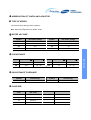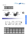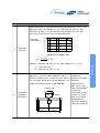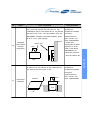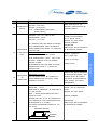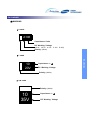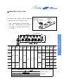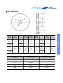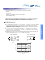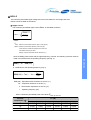
1
Tantalum Capacitor ( SCL Series )
The SCL series is a slim type of conventional SCS series.
Its ability is same as SCS series even though it has thinner thickness that is
max. 64% of SCS series.
General Features
- Environment-Friendly (Pb-free) tantalum capacitor
- Low-profile case size
- Reduced thickness up to 64% of SCS series
- Molded Case available in four case codes.
- Compatible with automatic pick and place equipment.
- Meets or Exceeds EIA standard 535BAAC .
Applications
- Reduced electronic equipments : mobile phone, PDA, MP3, LCD module etc. - Smoothing
- Circuit of DC-DC Converters & Output side of AC-DC Converters
- De-Coupling Circuit of High Speed ICs & MPUs
- Various Other High Frequency Circuit Applications
Part Numbering
TC
1
●
SCL 0J
2
3
●
●
106
4
●
M
5
●
S
6
●
A
7
●
R
8
●
0
Abbreviation of Tantalum Capacitor
Capacitance Tolerance
Type of Series
Case size
Rated Voltage
Packing
Capacitance Tolerance
Packing Polarity
SCL Series
- Terminations: 100 % Sn , RoHS compliant.
1 ABBRIVIATION OF TANTALUM CAPACITOR
●
2 TYPE OF SERIES
●
The symbol shows the type of the capacitor.
SCL : Samsung Capacitor Low-profile series
3 RATED VOLTAGE
●
Symbol
DC Rated Voltage
Symbol
DC Rated Voltage
0E
2.5
1C
16
0G
4
1D
20
0J
6.3
1E
25
1A
10
1V
35
4 CAPACITANCE
●
Capacitance ( ㎌)
PicoFarad ( ㎊)
105
1.0
10×105
684
0.68
68×10 4
106
10.0
10×106
475
4.7
47×10 5
5 CAPACITANCE TOLERANCE
●
Symbol
Tolerance(%)
Symbol
Tolerance(%)
K
±10
M
±20
6 CASE SIZE
●
0
Case
EIA Code
S
3216-12
T
3528-12
U
6032-15
V
7343-18
SCL Series
Symbol Capacitance ( ㎌) Pico Farad (㎊) Symbol
7 PACKING
●
Symbol
Packing Code
A
7 inch
C
13 inch
8 PACKING POLARITY
●
Taping and
Reel for Chip
Taping and
R
Reel for Chip
Direction
of Feed
Tape
Bulk
L
B
Direction
of Feed
+ Polarity Mark
+ Polarity Mark
SCL Series
APPEARANCE AND DIMENSON
0
Code
EIA Code
DIMENSION (mm)
L
W1
W2
H
Z
R
2012-09
2.0 ±0.2
1.25 ±0.2
0.9 ±0.1
0.95max
0.5 ±0.2
S
3216-12
3.2 ±0.2
1.6 ±0.2
1.2 ±0.1
1.2max
0.8 ±0.3
T
3528-12
3.5 ±0.2
2.8 ±0.2
2.2 ±0.1
1.2max
0.8 ±0.3
V
6032-15
6.0 ±0.3
3.2 ±0.3
2.2 ±0.1
1.5max
1.3 ±0.3
W
7343-18
7.3 ±0.3
4.3 ±0.3
2.4 ±0.1
1.8max
1.3 ±0.3
● Standard value and Case size
Ultra Flat Low Profile Tantalum Chip Capacitors
STANDARD VALUE AND CASE SIZE
W .V
4V
6.3V
10V
16V
Cap.(㎌)
(0G)
(0J)
(1A)
(1C)
4.7
475
6.8
685
(S)
10
106
(S)
(T)
15
156
22
226
S,T
S
(S),(T)
(T)
33
336
S,T
S,T
T
47
476
T
T
(T)
68
686
(T)
(T)
100
107
(T)
150
157
()Under Development
New products (2005.01~) are show n in blue.
Environmentally friendly tantalum chip capacitors w ith lead-free terminal/Conform to RoHS
SCL Series
RELIABILITY TEST CONDITION
NO
ITEMS
TEST CONDITION
PERFORMANCE
1
RATED DC VOLTAGE
-55℃ ~ +85℃
2.5∼35V
MEASURING FREQUENCY : 120±12Hz
2
CAPACITANCE
3
TANGENT OF LOSS
ANGLE
CAPACITANCE RANGE
MEASURING VOLTAGE : 0.5Vrms + 0.5∼2V DC
0.1∼330㎌
MEASURING CIRCUITS : EQUIVALENT SERIES
CIRCUIT
TOLERANCE ON CAP.
±10%, ±20%
MEASUREMENT SHALL BE MADE UNDER THE
SAME CONDITIONS AS THOSE GIVEN FOR THE
MEASUREMENT OF CAPACITANCE.
THE RATED DC VOLTAGE SHALL BE APPLIED
TO TERMINALS ACROSS THE TEST CAPACITOR
Cx, BY THE METHOD AS SHOWN BELOW. THE
LEAKAGE CURRENT SHALL THEN BE
0.01CV or 0.5㎂
WHICHEVER IS GREATER
MEASURED AFTER CHARGE FOR 5 MIN.
MEASURING CIRCUITS
S2
RS
4
LEAKAGE CURRENT
1
V
C
-
x
+
-
WHERE
RS : STANDARD RESISTOR(PROTECTIVE R :1KΩ)
V : DC VOLTMETER OR ELECTRONIC
VOLTMETER
S1 : DC POWER SUPPLY SWITCH
S2 : PROTECTIVE SWITCH FOR A AMMETER
CX : TEST CAPACITOR
A : DC AM-METER FOR LEAKAGE CURRENT
AC VOLTAGE(0.5Vrms OR LESS) OF A
FREQUENCY SPECIFIED ON NEXT PAGE SHALL
BE APPLIED AND THE VOLTAGE DROP
ACROSS CAPACITOR TERMINALS SHALL BE
MEASURED
THE IMPEDANCE SHALL BE CALCULATED BY
5
IMPEDENCE
THE FOLLOWING EQUATION.
WHERE
Impedance Z =
E
I
E : VOLTAGE DROP ACROSS THE CAPACITOR
TERMINALS
I : CURRENT FLOWING THROUGH THE
CAPACITOR
(FREQUENCY : 100±10kHz)
SCL Series
+
A
S
NO
ITEMS
TEST CONDITION
PERFORMANCE
THE CAPACITOR SHALL BE SUBJECTED IN TURN TO PROCEDURES SPECIFIED
BELOW
STEP
TEMP.
1
6
CHANGE IN
TANGENT OF
CAPACITANCE
LOSS ANGLE
( ΔC )
(D.F.)
WITHIN
SPECIFIED
TABLE 1 ON
25±2℃
PAGE 13
TOLERANCE
TEMPERATURE
STABILITY
DURATION
2
-55
3
4
5
0
℃
-3
25±2℃
+85
+3
+125
2 HOURS.
+3
0
TABLE 1 ON
INITIAL VALUE
PAGE 13
0 TO +10% OF
TABLE 1 ON
INITIAL VALUE
PAGE 13
0 TO +12% OF
INITIAL VALUE
TABLE 1 ON
PAGE 13
℃ 2 HOURS.
VOLTAGE AS SPECIFIED ON NEXT PAGE IN A CYCLE OF 6±
0.5 MIN. WHICH CONSISTS OF 30±5 SEC. FOLLOWED BY A
DISCHARGE PERIOD OF APPROX. 5 MIN 30 SEC. AT A
TEMPERATURE OF +85℃ FOR 1,000 CYCLES.
AND THE CAPACITOR SHALL BE STORED UNDER
STANDARD ATMOSPHERIC CONDITIONS TO OBTAIN
THERMAL EQUILIBRIUM AFTER MEASUREMN\ENT.
MEASURING CIRCUIT
+
R1
S
V
SURGE TEST
+
-
-Cx
R2
WHERE
R1 : PROTECTIVE SERIES RESISTOR (33Ω)
R2 : DISCHARGE RESISTOR( 33Ω)
Cx : TEST CAPACITOR
V : DC VOLTAGE
S : SWITCH
RATED VOLTAGE
LIMIT
N/A
2.5V
SURGE VOLTAGE 3.1V
4V 6.3V 10V 16V 20V 25V 35V
5V
8V
13V 20V 26V 32V 45V
WITHIN 10X
ORIGINAL
LIMIT
WITHIN 12.5X
ORIGINAL
LIMIT
SCL Series
THE CAPACITOR SHALL BE SUBJECTED TO THE SURGE
7
WITHIN
ORIGINAL
25 MIN.
℃ 2 HOURS.
0
- 10 TO 0% OF
LEAKAGE
CURRENT
NO
ITEMS
TEST CONDITION
PERFORMANCE
WHEN OPERATING AT HIGH TEMPERATURE RANGE FROM 85℃ to 125℃, THE
OPERATION SHALL BE CARRIED OUT AT A DERATED VOLTAGE OR LESS
DERATING VOLTAGE Vt AT ANY TEMPERATURE BETWEEN 85℃ AND 125℃
SHALL BE CALCULATED BY THE FOLLOWING EQUATION
VOLTAGE
DERATING %
100
80
60
40
8
DERATING
20
VOLTAGE
0
-55
0 20
85
125
OPERATING TEMPERATURE
= Vr −
Vr − Vd
(T − 85)
40
WHERE Vt : DERATED VOLTAGE AT ANY TEMP. BETWEEN 85℃ to 125℃
Vd : DERATED VOLTAGE AT 125℃
APPLY PRESSURE IN THE DIRECTION OF THE
THERE SHALL BE NO
ARROW AT A RATE OF ABOUT 0.5MM/SEC. UNTIL IT
EVIDENCE OF
REACHES A BENT WIDTH OF 3MM AND HOLD FOR 30 MECHANICAL DAMAGE.
SEC. THE TEST BOARD SHALL BE IEC 40(S) 541. FOR
ELECTRICAL
OTHER PROCEDURES REFER TO IEC 40(S) 541.
CHARACTERISTICS
SHALL SATISFY THE
INITIAL REQUIREMENT.
Pressure rod
ELECTRODE
9
IF THERE ARE
10
ELECTRODES ON BOTH
20
(TERMINAL
Board
SURFACES, IT SHALL
SATISFY THE ABOVE
STRENGTH)
REQUIREMENT ON
WHICHEVER SURFACE
IT MAY BE FIXATED ON.
45±2
45±2
SCL Series
Vr : RATED VOLTAGE
NO
ITEMS
TEST CONDITION
PERFORMANCE
A STATIC LAOD OF 19.6N USING A R0.5 SCRATCH
THERE SHALL BE NO
TOLL SHALL BE APPLIED ON THE CORE OF THE
EVIDENCE OF
COMPONENT AND IN THE DIRECTION OF THE ARROW MECHANICAL DAMAGE.
AND HOLD FOR 5 SEC. THE TEST BOARD SHALL BE
ELECTRICAL
IEC 40(S)541. HOWEVER THE BASE MATERIAL SHALL
CHARACTERISTICS
BE G-10 or FR-4 (ANSI GRADE)
SHALL SATISFY THE
ADHESION
10
Scratch tool
(ELECTRODE
PEELING
Board
INITIAL REQUIREMENT.
IF THERE ARE
ELECTRODES ON BOTH
R0.5
SURFACES, IT SHALL
SATISFY THE ABOVE
STRENGTH)
REQUIREMENT ON
WHICHEVER SURFACE
IT MAY BE FIXATED ON.
Chip
A ROD OF 9.8N USING A R0.5 PRESSURE ROD SHALL THERE SHALL BE NO
BE APPLIED TH THE CENTER IN THE DIRECTION OF
EVIDENCE OF
THE ARROW AND HOLD FOR 10 SEC
MECHANICAL DAMAGE.
ELECTRICAL
CHARACTERISTICS
SHALL SATISFY THE
11
CORE BODY
R0.5
Pressure
Chip
STRENGTH
W
0.5L
L
L>W
INITIAL REQUIREMENT.
SCL Series
Chip
NO
ITEMS
TEST CONDITION
SOLDER TEMPERATURE : 245±5℃
12
SOLDERABILITY
[Pb-free]
DIP TIME : 3±0.5 SEC.
SOLDER : Sn-3Ag-0.5Cu
FLUX : ROSIN(KSM2951)+Solvent(ISA)
PERFORMANCE
MORE THAN 95% OF THE
TERMINAL SURFACE MUST BE
SOLDERED NEWLY.
(ROSIN 25WT%)
PREHEAT : 100∼110℃ FOR 30 SEC.
TEMPERATURE : 260±5℃
±5% OF INITIAL VALUE
DIP TIME : 10 ±1 SEC
TANGENT OF LOSS ANGLE :
ALL SAMPLES SHALL BE DIPPED IN SOLDER
BATH. MEASUREMENT SHALL BE MADE AT
ROOM TEMPERATURE AFTER 1~2 HOURS OF
RESISTANCE
13
TO SOLDERING
HEAT
CHANGE IN CAPACITANCE :
COOLING TIME.
CONVECTION REFLOW
PREHEAT : 150∼190℃ FOR 130 SEC.
PEAK TEMPERATURE : 260±5℃ FOR 10 SEC.
METHOD : SAMPLES SHALL BE PASSED
REFLOW 3 TIMES.
APPEARANCE :
THERE SHALL BE NO EVIDENCE
OF MECHANICAL DAMAGE. .
Change in capacitance:
±10% of initial value
Tangent of loss angle:
Leakage Current :
TEMPERATURE AFTER 3∼4 HOURS OF
COOLING TIME.
THERE SHALL BE NO EVIDENCE
RESISTANCE
14
TO
CLEAN TEST
VIBRATION
IMMERSION CLEANING
THE CAPACITOR SHALL BE CLEANED AT
OF MECHANICAL DAMAGE. AND
MARKING SHALL BE LEGIBLE.
ROOM TEMPERATURE FOR 60sec. USING
ELECTRICAL CHARACTERISTICS
ISOPROPYL ALCOHOL
SHALL SATISFY THE INITIAL
REQUIREMENT.
FREQUENCY : 10 to 55 to 10Hz (in 1 min.) MAX
CHANGE IN CAPACITANCE :
AMPLITUDE : 1.5 mm.
WITHIN : ±5% OF THE INITIAL
DIRECTION OF VIBRATION : IN DIRECTION OF
X,Y AND Z AXES
VALUE
TANGENT OF LOSS ANGLE :
TIME : 2 HOURS EACH DIRECTION AND 6
15
HOURS IN TOTAL
DURING THE LAST 30 min. OF VIBRATION IN
LEAKAGE CURRENT :
EACH DIRECTION, THE CAPACITANCE SHALL
APPEARANCE :
BE MEASURED 3 TO 5 TIMES.
FOR OTHER PROCEDURES REFER TO IEC
THERE SHALL BE NO EVIDENCE
OF MECHANICAL DAMAGE. .
Pub. 68-2-6.
MOUNTING METHOD
SOLDER
ALUMINA
BOARD
SCL Series
MEASUREMENT SHALL BE MADE AT ROOM
LEAKAGE CURRENT :
NO
16
ITEMS
MOISTURE
RESISTANCE
TEST CONDITION
PERFORMANCE
THE CAPACITOR SHALL BE STORED AT A
CHANGE IN CAPACITANCE :
TEMPERATURE OF 40±2℃ AND RELATIVE
HUMIDITY OF 90% TO 95% FOR 500±8 HOURS.
WITHIN : ±10% OF THE
INITIAL VALUE
ELECTRICAL MEASUREMENTS SHALL BE MADE
TANGENT OF LOSS ANGLE :
AFTER BEING BOARD AT ROOM TEMPERATURE
FOR 1∼2 HOURS. FOR OTHER PROCEDURES
LEAKAGE CURRENT :
REFER TO IEC Pub. 68-2-2.
17
LOAD LIFE
TEMPERATURE
VOLTAGE
TIME
85℃
RATED VOLTAGE
2,000 HOURS
DERATED
125℃
VOLTAGE
2,000 HOURS
THE CAPACITOR SHALL BE PLACED IN A
CHANGE IN CAPACITANCE :
WITHIN : ±10% OF THE
INITIAL VALUE
TANGENT OF LOSS ANGLE :
LEAKAGE CURRENT :
CIRCULATING AIR OVEN AT AN AMBIENT.
ELECTRICAL MEASUREMENTS SHALL BE MADE
FOR 1~2 HOURS.
THE CAPACITOR SHALL BE STORED AT A
STORAGE AT
18
19
TEMPERATURE OF -55±2℃ FOR 240±8 HOURS
WITHOUT LOAD.
LOW
ELECTRICAL MEASUREMENTS SHALL BE MADE
TEMPERATURE
AFTER BEING STORED AT ROOM TEMPERATURE
FOR 1~2 HOURS
Thermal Shock
STEP
TEMPERATURE
TIME
1
-55 0 ℃
-3
30 ±3 MIN
2
25 ± 5℃
15 ±2 MIN
3
125 0 ℃
-3
30 ±3 MIN
4
25 ± 5℃
15 ±2 MIN
CHARACTERISTICS SHALL
SATISFY THE INITIAL
REQUIREMENT.
CHANGE IN CAPACITANCE :
WITHIN : ±10% OF THE
THE CAPACITOR SHALL BE SUBJECTED TO EACH
SPECIFIED TEMPERATURE FOR EACH SPECIFIED
TIME IN THE TABLE ABOVE
THESE 4 STEP CONSTITUTES ONE CYCLES SHALL
BE PERFORMED CONTINUOUSLY
ELECTRICAL
INITIAL VALUE
TANGENT OF LOSS ANGLE :
LEAKAGE CURRENT :
SCL Series
AFTER BEING STORED AT ROOM TEMPERATURE
PACKAGING
● MARKING
▶ S CASE
A106
Capacitance Code
DC Working Voltage
(G:4V J:6.3V A:10V
Polarity (White)
C:16V D:20V)
▶ T CASE
Capacitance in ㎌
DC Working Voltage
Polarity (White)
▶ V,W CASE
Polarity (White)
10
35V
Capacitance in ㎌
DC Working Voltage
SCL Series
10
20V
▶ R CASE
JA
Capacitance Code
DC Working Voltage
(G:4V J:6.3V A:10V
Polarity (White)
C:16V D:20V)
Capacitance Range
1 DIGIT
2 DIGIT
< 1.0 ㎌
A Small Letter
A Small Letter
1.0 ㎌≤ Cap.< 10㎌
A Capital Letter
A Small Letter
≥ 10 ㎌
A Capital Letter
A Capital Letter
V
4
6.3
10
16
gj
jj
aj
cj
0.47
gs
js
as
cs
ds
0.68
gw
jw
aw
cw
dw
1.0
Ga
Ja
Aa
Ca
2.2
Gj
Jj
Aj
Cj
3.3
Gn
Jn
An
4.7
Gs
Js
As
6.8
Gw
Jw
10
GA
JA
GJ
JJ
㎌
0.22
20
0.33
1.5
15
22
AA
Cs
SCL Series
【Code Reference 】
● EMBOSSED PLASTIC TAPE
Embossed
Carrier
Right hand
Orientation available
The tantalum chip capacitors shall be packaged
in tape and reel form for effective use.
- Tape : Semitransparent embossed plastic
- Cover tape : Attached with press, polyester
- The tension of removing the cover tape,
F=10∼70g
Embossed
D1
E
W
F
A
B
P0
P1
P2
K
Case
Code
W±0.3
(±0.01
2)
F±0.1
(±0.00
4)
E±0.1
(±0.00
4)
P O±0.1
(±0.00
4)
P1±0.1
(±0.00
4)
P2±0.1
(±0.00
4)
D1+0.1
(+0.00
4)
J*
D2Min.
t
A±0.2
(±0.00
8)
B±0.2
(±0.00
8)
K±0.2
(±0.00
8)
ø0.6
(0.024)
0.25
(0.0098)
0.98
(0.039)
1.80
(0.071)
1.0
(0.039)
1.4
(0.055)
2.3
(0.091)
1.1
(0.043)
1.9
(0.075)
3.5
(0.138)
1.3
(0.051)
3.3
(0.130)
3.8
(0.150)
1.3
(0.051)
3.7
(0.146)
6.4
(0.252)
1.6
(0.063)
4.8
(0.189)
7.7
(0.303)
1.9
(0.075)
R*
8
(0.315)
4
(0.157)
3.5
(0.138)
S
2
(0.079)
1.75
(0.069)
4
(0.157)
ø1.5
(0.059)
ø1.0
(0.039)
0.2
(0.008)
T
V
12
(0.472)
5.5
(0.217)
8
(0.315)
ø1.5
(0.059)
0.3
(0.012)
W
Cover Tape
15˚
F
Removal speed
50mm/sec
SCL Series
D2
t
● REEL DIMENSION
Tape
Width
ø178
(7)
12mm
N Min.
ø70
(2.756)
ø60
(2.362)
C±0.5
(±0.020)
ø13
(0.512)
D±0.5
(±0.020)
B±051
(±0.020)
ø21
(0.827)
2
(0.079)
8mm
ø330
(13)
ø80
(3.150)
ø13
(0.512)
ø21
(0.827)
12mm
Case Size
2
(0.079)
10
(0.394)
14
(0.551)
10
(0.394)
14
(0.551)
t+0.5
(±0.020)
R
2
(0.079)
0.99
(0.039)
2
(0.079)
0.99
(0.039)
180mm(7") reel
330mm(13") reel
J
4,000pcs
-
R
3,000pcs
-
S, T
2,000pcs
8,000pcs
V, W
500pcs
2,500pcs
reference
SCL Series
8mm
A±2
(±0.079)
APPLICATION MANUAL
The operational attentions to the use of the tantalum capacitors are as follows:
- Electrical
- Environmental
- Conditions for mounting on equipment and circuit boards
- Mechanical vibration, shock
If the tantalum capacitors are used without satisfying any one of these conditions, the probability of
short-circuiting, leakage current, ignition or other problems to occur increases. To avoid such
problems, observe the following precautions when using the tantalum capacitors.
● OPERATING VOLTAGE
▶ The voltage derating factor should be as great as possible. Under normal conditions, the operating
voltage should be reduced to 50% or less of the rating. It is recommended that the operating
voltage be 30% or less of the rating, particularly when the tantalum capacitors are used in a lowimpedance circuit (see Figs. 1, 2, and 3).
▶ When the tantalum capacitors are to be used at an ambient temperature of higher than 85℃, the
recommended operating range shown in Fig. 3 should not be exceeded.
Power supply filter
Power
~
supply
Power supply bypass
+
+
+
circuit
+
-
-
Fig. 1
Fig. 2
100
80
60
40
20
0
-55 -40 -20 0 20 40 60
85
100 125
OPERATING TEMPERATURE
Fig. 3
IC
SCL Series
▶ For circuits in which a switching, charging, discharging, or other momentary current flows, it is
recommended that the operating voltage be 30% or less of the rating, with a resistor connected in
series to limit the current to 300 mA or less.
● RIPPLE
The maximum permissible ripple voltage and current are related to the ratings case size.
Please consult us detail in formations.
▶ Ripple Current
The maximum permissible ripple current, IMAX, is calculated as follows :
PMAX
IMAX =
ESR(f)
where:
IMAX
: Maximum permissible capacitor ripple current (Arms).
PMAX : Maximum permissible capacitor power loss (W).
Varies with the ambient temperature and case size.
Calculated according to Table
ESR(f): Capacitor equivalent series resistance (Ω).
Since the ESR(f) value varies with the ripple frequency, however, the following correction must be
made in accordance with the operating frequency (see Fig. 4).
SCL Series
ESR(f) = K · ESR(120)
K : Coefficient for the operating frequency (Fig. 4).
ESR(120) = Tan δ · Xc =
Tan δ
2πfC
where:
ESR(120) : Equivalent series resistance at 120 Hz (Ω).
Xc : Capacitive reactance at 120 Hz (Ω).
C : Electrostatic capacitance at 120 Hz (μF).
f : Operating frequency (Hz).
Table.1 Maximum permissible power loss values (PMAX) by case size
Ambient
temperature (℃ )
PM A X(W)
J
P
S
T
U
V
25
0.015
0.015
0.030
0.030
0.030
0.050
55
0.010
0.010
0.019
0.019
0.019
0.032
85
0.005
0.005
0.010
0.010
0.010
0.018
Table.2 Hz VS K
10
Frequency
K
120
1.0
400
0.8
1k
0.65
10k
0.50
20k
0.45
40k
0.43
100k
0.40
1M
0.35
1.0
0.1
0.01
100
1K
10K
100K
1M
FREQUENCY(Hz)
Fig.4 Correction Coefficient(K)
▶ Ripple Voltage
If an excessive ripple voltage is applied to the tantalum capacitors, their internal temperature
rises due to Joule heat, resulting in the detriment of their reliability.
SCL Series
▷ The tantalum capacitors must be used in such a conditions that the sum of the Working Voltage
and ripple voltage peak values does not exceed the rated voltage (Fig. 5)
▷ Ensure that an reverse voltage due to superimposed voltages is not applied to the capacitors.
▷ The maximum permissible ripple voltage varies with the rated voltage. Ensure that ripple voltage does
not exceed the values shown in Figs 6 and 7. If, however, the capacitors are used at a high
temperature, the maximum permissible ripple voltage must be calculated as follows:
Vrms(at 55℃) = 0.7 x Vrms(at 25℃)
Vrms(at 85℃) = 0.5 x Vrms(at 25℃)
Vrms(at 125℃) = 0.3 x Vrms(at 25℃)
100
10
100
100
50 V
35 V
25 V
20 V
16 V
10 V
6.3/7 V
4V
2.5 V
10
100
100
100
1
10
100
50 V
35 V
25 V
20 V
16 V
10 V
6.3/7 V
4V
2.5 V
100
100
1
10
100
Frequency(Hz)
Frequency(Hz)
Fig.6 Maximum permissible ripple voltage
Fig.7 Maximum permissible ripple voltage
(P,A,B)
(C,D)
● REVERSE VOLTAGE
▷ The tantalum capacitors must not be operated and changed in reverse mode. And also the
capacitors must not be used in an only AC circuit.
▷ The tantalum capacitor dielectric has a rectifying characteristics. Therefore, when a reverse
voltage is applied to it, a large current flows even at a low reverse voltage.As a result,it may
spontaneously generate heat and lead to shorting.
▷ Make sure that the polarity and voltage is correct when applying a multi-meter or similar testing
instrument to the capacitors because a reverse voltage or overvoltage can be accidentally
applied.
▷ When using the capacitors in a circuit in which a reverse voltage is applied, consult your local
SAMSUNG ELECTRO-MECHANICS agent. If the application of an reverse voltage is
unavoidable, it must not exceed the following values.
At 20°C: 10% of the rated voltage of 1 V, whichever smaller.
At 85°C: 5% of the rated voltage or 0.5 V, whichever smaller.
SCL Series
Solid tantalum capacitors are polarized device and may be permanently damaged or destroyed, if
connected with the wrong polarity.
● RELIABILITY OF TANTALUM CAPACITORS
▶ General
The failure rate of the tantalum capacitor varies with the digression ratio, ambient temperature, circuit
resistance, circuit application, etc.
Therefore, when proper selections are made so as to afford additional margins, higher reliability can
be derived from the tantalum capacitors. Some examples of actual failure rates are presented below
for your reference.
▶ Failure Rate Calculation Formula
The tantalum capacitors are designed to work at their basic failure
rates shown in Table 3 that prevail when the rated voltage is applied for 1000 hours at 85℃.
Table 3 Basic failure rate
C lassif ication
S C E ,SV E
Low E S R ty pe
S C M ,S V M
U ltra-M in iatur iz ation Ty pe( 060 3)
SC L
Low -p ro file Ty pe
S C S ,SV S
S m all Ty pe
S C N ,S V N
S tanda rd ty pe
PC*
C ondu c tiv e P oly m er Ty pe
Basic failure rate
1% /10 00h
▷ Failure rate calculation formula
λuse = λ85 x KV x KR
λuse : Estimated capacitor failure rate under the operating conditions.
λ85 : Basic failure rate (Table 3)
KV :
KR :
Failure rate correction coefficient by the ambient temperature and derating factor.
Failure rate correction coefficient by the circuit resistance,
which is the series-connected resistance divided by the voltage applied to the capacitor.
This resistance is connected in series when the power supply side is viewed from the capacitor side.
K(derating factor)=operating voltage/rated voltage
SCL Series
TYPE
● RELIABILITY PREDICTION
Solid tantalum capacitors exhibit no degration failure mode during shelf storage and show a constantly
decreasing failure rate(i.e. , absence of wearout mechanism) during life tests. this failure rate is
dependent upon three important application conditions:DCvoltage, temperature, and circuit impedance.
Estimates of these respective effects are provided by the reliability nomograph.(Figure 8.)
The nomograph relates failure rate to voltage and temperature while the table relates failure rate to
impedance. These estimates apply to steady-state DC condition, and they assume usage within all
other rated conditions.
Standard conditions, which produce a unity failure rate factor, are rated voltage, +85℃, and 0.1 ohmper-volt impedance.
While voltage and temperature are straight-forward, there is sometimes difficulty in determining
impedance. What is required is the circuit impedance seen by the capacitor. If several capacitors are
connected in parallel, the impedance seen by each is lowered by the source of energy stored in the
other capacitors. Energy is similarly stored in series inductors.
Voltage "de-rating" is a common and useful approach to improved reliability. It can be persued too far,
however , when it leads to installation of higher voltage capacitors of much larger size.
Failure rate is conventionally expressed in
units of percent per thousand hours. As a
sample calculation, suppose a particular
batch of capacitors has a failure rate of 0.5%
/ Khr under standard conditions.
What would be the predicted failure rate at
0.7times rated voltage, 60℃ and 0.6Ω/V?
120
110
101
100
80
60
50
The failure rate estimate is then :
0.5 × 7 × 10-2 × 0.4
100
90
70
The nomgraph gives a factor of 7 × 10⁻² and
the table gives a factor of 0.4.
102
40
Connect the temperature
and applied voltage ratio
of interest with a straight
edge. The multiplier of
failure rate is given at the
inersection of this
line with the model scale.
10-1
1.0
0.9
0.8
0.7
0.6
0.5
-2
10
Given T1&v1 Read Failure
Rate Multiplier F1
Given T, & F2
Read Reguired Voltage V2
Given F3 & V3
Read Allowable Temp T3
10-3
0.4
0.3
0.2
-4
10
= 1.4 × 10⁻² or 0.014%/Khr
30
10-5
0.1
20
T
Fig.8 Reliability Nomograph
F
V
SCL Series
It is possible to lose more via higher
inherent failure rate than is gained by
voltage derating. SAMSUNG typically
recommends 50% derating, especially in
low impedance circuits.
Table 4 Circuit Impedance Reliability Factors
C ircuit Im pedanc e
(ohm s/volt)
Failure R ate Im pedanc e
(m ultiplying fac tor )
0.1
1.0
0.2
0.8
0.4
0.6
0.6
0.4
0.8
0.3
1.0
0.2
2.0
0.1
3 or gre ater
0.0 7
● MOUNTING PRECAUTIONS
▶ Limit Pressure on Capacitor Installation with Mounter
A capacitor that has been damaged should be discarded to avoid later problems resulting from
mechanical stress.
capacitors using an absorber, centering tweezers, or the like. An excessively low absorber setting
position would result in not only the application of undue force to the capacitors but capacitor and
other component scattering,circuit board wiring breakage, and / or cracking as well, particularly
when the capacitors are mounted together with other chips having a height of 1 mm or less.
▶ Flux
▷ Select a flux that contains a minimum of chlorine and amine.
▷ After flux use, the chlorine and amine in the flux remain and must therefore be removed.
▶ Recommended Soldering Pattern Dimensions
L
z
Fig. 9
x
W
x
y
Capacitor
Pattern
SCL Series
Pressure must not exceed 4.9 N with a tool end diameter of 1.5mm when applied to the
Table 4 Recommended soldering pattern dimensions(mm)
Dimensions
Capacitors
size
Pattern dimensions
L
W
x
y
z
J
1.6
0.85
0.9
1.0
0.7
P
2.0
1.25
1.2
1.1
0.8
S
3.2
1.6
1.6
1.2
1.2
T
3.5
2.8
1.6
2.2
1.4
U
5.8
3.2
2.3
2.4
2.4
V
7.3
4.3
2.3
2.6
3.8
Case
▶ Chip Soldering Temperature and Time
Capacitors are capable of withstanding the following soldering temperatures and conditions;
▷ Waved soldering
Capacitor body temperature : 230℃∼ 260℃
Time : 5 seconds or less
▷ Reflow soldering see figures
Heating
260℃ Max
200
Cooling
Pre-heating
100
100
200
300
400
Time(sec)
Figure : Typical Temperature Profile of Reflow Soldering (pb-free)
SCL Series
Temp.℃
▷ Soldering with a soldering iron
The use of a soldering iron should be avoided wherever possible. If it is
unavoidable, follow the instructions set forth in Table 5. The time of soldering with an iron
should be one.
Table 5
Soldering-iron tip temperature
350℃
MAX
Time
3 sec
MAX
Soldering-iron power
30 W
MAX
▶ Cleaning after Mounting
The following solvents are usable when cleaning the capacitors after mounting. Never use
a highly active solvent.
- Halogen organic solvent (HCFC225, etc.)
- Petroleum solvent, alkali saponifying agent, water, etc.
Circuit board cleaning must be conducted at a temperature of not higher than 50°C and for
an immersion time of not longer than 30 minutes. When an ultrasonic cleaning method is
used, cleaning must be conducted at a frequency of 48 kHz or lower, at an vibrator output
of 0.02 W/cm3, at a temperature of not higher than 40°C, and for a time of 5 minutes or shorter.
NOTE 1: Care must be exercised in cleaning process so that the mounted capacitor will not come
into contact with any cleaned object or the like or will not get rubbed by a stiff brush or
the like. If such precautions are not taken particularly when the ultrasonic cleaning
method is employed, terminal breakage may occur.
NOTE 2: When performing ultrasonic cleaning under conditions other than stated above, conduct
adequate advance checkout.
● OTHER
▷ For further details, refer to EIAJ RCR-2368, Precautions and Guidelines for Using Electronic Device
Tantalum Capacitors.
▷ If you have any questions, feel free to contact your local SAMSUNG ELECTRO-MECHANICS agent.
SCL Series
- Alcoholic solvent (IPA, ethanol, etc.)