1
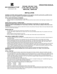
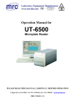
FILTERBREW &
SERVING CONCEPT
TECHNICAL MANUAL
TM_EN
Part No.: 1764092_01
CONTENT
FILTERBREW & SERVING CONCEPT
CONTENT......................................................................................................................................................... 2
GENERAL............................................................................................................................................................ 4
Introduction...............................................................................................................................................................4
Warnings.....................................................................................................................................................................4
Precautions.................................................................................................................................................................4
Intended use...............................................................................................................................................................4
CLEANING AND CARE............................................................................................................................ 5
Rinse Thermos, Decanter and Serving station...................................................................................................5
Dayly cleaning............................................................................................................................................................6
Weekly cleaning.........................................................................................................................................................6
Cleaning Serving station..........................................................................................................................................7
Exterior cleaning.......................................................................................................................................................7
PROGRAMMING........................................................................................................................................... 8
A-2, DA-4, Thermos A, Mega Gold A....................................................................................................................8
Cater......................................................................................................................................................................... 10
Tower........................................................................................................................................................................ 14
HVA/HVM................................................................................................................................................................ 16
Grinder Original ................................................................................................................................................... 17
POSSIBLE SOLUTION............................................................................................................................. 19
Original A/M............................................................................................................................................................ 19
Cater, Tower, HVA/HVM....................................................................................................................................... 20
ELECTRICAL SCHEMATICS................................................................................................................. 21
A-2............................................................................................................................................................................. 21
M-2............................................................................................................................................................................ 22
DA-4.......................................................................................................................................................................... 23
DM-4......................................................................................................................................................................... 24
Mega Gold A, Termos A......................................................................................................................................... 25
Mega Gold M, Termos M, Office.......................................................................................................................... 26
Single Cater............................................................................................................................................................. 27
Cater......................................................................................................................................................................... 28
Tower 3x400VAC+Zero+Ground..................................................................................................................... 29
Tower 3x230VAC+Ground................................................................................................................................. 30
Tower 3x400VAC+Ground................................................................................................................................. 31
Grinder Original ................................................................................................................................................... 32
V-2............................................................................................................................................................................. 33
HVA/HVM 1-Phase................................................................................................................................................ 34
HVA/HVM 3-Phase................................................................................................................................................ 35
2
CONTENT
FILTERBREW & SERVING CONCEPT
EXPLODED VIEW....................................................................................................................................... 36
A-2............................................................................................................................................................................. 36
M-2............................................................................................................................................................................ 38
DA-4.......................................................................................................................................................................... 40
DM-4......................................................................................................................................................................... 42
Mega Gold A........................................................................................................................................................... 44
Mega Gold M........................................................................................................................................................... 46
Thermos Office...................................................................................................................................................... 48
Thermos A............................................................................................................................................................... 50
Thermos M.............................................................................................................................................................. 52
Cater......................................................................................................................................................................... 54
Tower........................................................................................................................................................................ 56
Grinder Original ................................................................................................................................................... 58
HVA........................................................................................................................................................................... 60
V-2............................................................................................................................................................................. 62
Serving station 2.5L............................................................................................................................................... 63
Serving station 5L.................................................................................................................................................. 65
DIMENSION................................................................................................................................................... 67
A-2/M-2.................................................................................................................................................................... 67
DA-4/DM-4............................................................................................................................................................. 68
Thermos A/M.......................................................................................................................................................... 69
Mega Gold A/M....................................................................................................................................................... 70
Single Tower............................................................................................................................................................. 71
Tower........................................................................................................................................................................ 72
Single Cater/ Tea Cater......................................................................................................................................... 73
Cater......................................................................................................................................................................... 74
Serving station 5L.................................................................................................................................................. 75
Serving station 2.5L............................................................................................................................................... 76
V-2............................................................................................................................................................................. 77
HVA/HVM................................................................................................................................................................ 78
Some important information may appear in textboxes seen below
IMPORTANT!
INFO.
CAUTION!
INFO.
More INFO.
Note
INFO.
3
GENERAL
FILTERBREW & SERVING CONCEPT
Introduction
Thank you for choosing a FILTERBREWER coffee machine.
We hope you enjoy it !
Read the user guide before using the machine.
This guide contains important instructions for
proper and safe use of the vending machine.
Always keep this guide close at hand for future
reference.
Warnings
Never immerse the machine, plug or mains
cable in water because there is a danger of
electric shock.
The appliance is not intended for use by
persons (including children) with reduced
physical, sensory or mental capabilities, or
lack of experience and knowledge, unless they
have been given supervision or instruction
concerning the use of the appliance by a person
responsible for their safety.
Children should be supervised to ensure they
do not play with the appliance.
Do not use the machine if the mains cable, plug
is damaged or the machine has fallen down.
If the mains cable is damaged it must be
replaced by the manufacturer, service agent or
similarly qualified persons in order to avoid a
hazard.
Only plug the machine into a properly installed
earthed safety socket whose line voltage
matches the technical data for the machine.
Precautions
Do not use the machine outdoors so it can be
exposed to weather (rain, snow, frost). It will
cause material damage to the machine.
Do not try to open the machine or repair it in
any way. To avoid danger only have the machine
repaired in a technical workshop, Service
Centre or by a qualified person.
Remove the mains cable from the socket when
the machine is not in use for longer periods. To
do this, pull the plug not the cable.
This appliance must be placed in a horizontal
position which is resistant to any water that
may leak.
Place the machine out of the reach of children.
Position the mains cable so that people cannot
trip over it. Keep it away from sharp edges and
heat sources.
The new hose-sets supplied with this appliance
are to be used, old hose-sets must not be reused.
This appliance is not suitable for installation in
an area where a water jet could be used.
This appliance must not be cleaned by a water
jet.
Intended use
This appliance is intended to be used in
household and similar applications such as:
- Staff kitchen areas in shops.
- Offices and other commercial working
environments.
- On agricultural estates.
- By clients in hotels, motels and other
residential type environments.
- Bed and breakfast type environments.
4
For the optimal performance of the machine
these parameters shall not be exceeded:
- Maximum permissible inlet water pressure :
800KPa (8Bar)
- Minimum permissible inlet water pressure:
200KPa (2Bar)
- Maximum working temperature: 40°ºC
- Minimum working temperature: 10°ºC
CLEANING AND CARE
FILTERBREW & SERVING CONCEPT
Rinse Thermos, Decanter and Serving station
Before each brewing, rinse the thermos, decanter or serving station with fresh tap water.
When cleaning the outside, use a soft rag with liquid cleaning agent to prevent scratches.
CAUTION!
The machine should not be submerged
in water or washed in a dishwasher. it
will result in machine damage.
5
CLEANING AND CARE
FILTERBREW & SERVING CONCEPT
Dayly cleaning
Wash the thermos, decanter(B) and the filter holder with liquid solution for coffee machines. Always
remove the filter immediately and clean the filter holder daily, coffee will get moldy.
Clean the spray nozzle(A) and the surrounding area.
Use a soft rag and liquid solution that does not scratch.
A
B
B
Pitcher
PT No.110351
Weekly cleaning
Descaling and cleaning.
Pour 50 ml descaling / cleaning solution in a decanter and fill it up with cold water.
Pour the mixture in the machine and proceed with a brewing without a filterpaper or coffee.
Rinse the machine thoroughly by brewing at least 3 times with clean water so that the particles from
descaling solution disappear.
Regular descaling will ensure optimum brewing performance and a longer life of the machine.
When cleaning the decanter in a dishwasher. Dismantle lid and place decanter upside down in the
dishwasher.(A)
A
Descaling agent
PT No. 110412
6
CLEANING AND CARE
FILTERBREW & SERVING CONCEPT
Cleaning Serving station
A
Disassemble the level tube and clean it
every week with the enclosed brush.
Take off the main lid and clean the mixer
tube(A).
Cleaning of Serving station
IMPORTANT!
Rinse the inside of
the serving station
several times with
fresh tap water.
Fill the serving station with hot water. ( Full
brewing without coffee and filter ).
Put 1 tablespoon with cleaning powder in the
serving station and wait at least 15 minutes.
Tap out 2/3 of the cleaning solution.
Clean the serving station with the cleaning brush.
Rinse the serving station with fresh tap water several times before reuse.
OPTIONS
Part No.
CLEANING PARTS
110102-02
Cleaning powder
1104231
Cleaning brush
1103360
Cleaning brush for level tube,
mixer tube
Exterior cleaning
When cleaning exterior of the machine, use a soft rag with liquid cleaning agent
to prevent scratches.
7
PROGRAMMING
FILTERBREW & SERVING CONCEPT
A-2, DA-4, Thermos A, Mega Gold A
Select machine type
Enter the procedure to select machine type is the following:
Press all three buttons
,
and
at the same time
before turning on the mains switch The buzzer beeps once.
The display shows the current setting.
Step up with button
Press the button
MACHINE
TYPE
8
and step down with button
.
to save setting and exit to normal mode.
DISPLAY
CUPS
CUPS TIME
BUZZER TIME
DA/A-2
T1
4-12
9.25 s
247
Termos A
T2
4-15
9.25 s
292
Mega A
T3
4-17
9.25 s
344
PROGRAMMING
FILTERBREW & SERVING CONCEPT
A-2, DA-4, Thermos A, Mega Gold A
Adjust water amount
Adjust amount of brew water
Press the buttons
and
at same time in 5 seconds.
The buzzer beeps twice. Display shows 0.
- Press the
button to increase amount of water.
- Press the
button to decrease amount of water.
- 1 step = 5%
- Press the
button to confirm the change.
ADJUST
DISPLAY
25%
5
20%
4
15%
3
10%
2
5%
1
0%
0
-5%
-1
-10%
-2
-15%
-3
-20%
-4
-25%
-5
Adjust brew time
Adjust the brew time
Press the buttons
and
at same time in 5 seconds.
The buzzer beeps four times. Display shows 0.
- Press the
button to increase brewing time.
- Press the
button to decrease brewing time.
- 1 step = 5%
- Press the
Display shows
button to confirm the change.
and machine is ready to use.
9
PROGRAMMING
FILTERBREW & SERVING CONCEPT
Cater
Normal operation with reduced outlet time
This mode is entered by pressing the
and
before turning the
mains switch on. The buzzer gives a 5s beep to indicate this mode.
This machine operates like in normal mode but the outlet times are reduced by
90% in order to allow faster adjustment of valve times.
Adjusting of water temperature
Press buttons
and
at the same time for 5 seconds until you
hear one beep. Display shows the present setting
Adjust with the buttons
= (increase) and
Confirm the new settings by pressing the
70°0C = min. temperature.
96°0C = max. temperature.
= (decrease).
button.
Adjusting of temperature sensor
ADJUST
DISPLAY
+5°C
5
+4°C
4
+3°C
3
+2°C
2
+1°C
1
0
0
-1°C
-1
-2°C
-2
-3°C
-3
-4°C
-4
-5°C
-5
10
In this mode a temperature offset for the NTC sensor can be adjusted.
The procedure to enter this mode is the following:
Press buttons
,
and
at the same time for 5
seconds until you hear 2 beeps.
The display shows the current setting.
Adjust with the buttons
Pressing the
mode.
= (increase) and
= (decrease).
button to save new settings and return to normal
PROGRAMMING
FILTERBREW & SERVING CONCEPT
Cater
Adjusting of water quantity
ADJUST
DISPLAY
25%
5
20%
4
15%
3
10%
2
5%
1
0%
0
-5%
-1
-10%
-2
-15%
-3
-20%
-4
-25%
-5
The procedure to enter this mode is the following:
Press buttons
and
at the same time for 5 seconds until
you hear 3 beeps.
The display shows the current setting.
Adjust with the buttons
Presse the
= (increase) and
= (decrease).
button to save new settings and return to normal
mode.
Adjusting of brewing time
ADJUST
DISPLAY
25%
5
20%
4
15%
3
10%
2
5%
1
0%
0
-5%
-1
-10%
-2
-15%
-3
-20%
-4
-25%
-5
Note
In this mode the time for the brewing done buzzer activation can be
adjusted. The procedure to enter this mode is the following:
Press buttons
and
at the same time for 5
seconds until you hear 5 beeps.
The display shows the current setting.
Adjust with the buttons
Presse the
= (increase) and
= (decrease).
button to save new settings and return to
normal mode.
The brewing time is the same regardless adjustment of the outlet valve time.
11
PROGRAMMING
FILTERBREW & SERVING CONCEPT
Cater
Select machine type
In this mode the machine type can be chosen. The procedure to enter this mode is the following:
Press buttons
,
and
at the same time
before turning the mains switch on until you hear 6 beeps.
The display shows the machine type.
Step up with button
Presse the
and step down with button
.
button to save new setting and return to
normal mode.
Outlet time (s)
Full
Half
Machine type
Display
Buzzer time (s)
1.8L
T1
56
113
90
2.5L
T2
79
158
90
Adjusting of flow water
IMPORTANT!
From date 091001 Cater is delivered with an adjustable PDS valve. This is to improve the
water flow into filter holder. The flow of PDS valve is set to 0.95 litre /minute. Depending
on the coarseness and amount of coffee that’s used when brewing, the flow might need
adjustments to prevent overflow in the filter holder.
A
PDS valve
12
Check the water flow.
This should be 0.95L/minute.
Adjust PDS valve if necessary.
(See fig.A)
Shall been done by an authorized
installation engineer
PROGRAMMING
FILTERBREW & SERVING CONCEPT
Cater
Test functions
Press buttons
and
at the same time before turning the mains
switch on, puts the control board into test mode for time and temperature
controlled machines.
For the other types pressing buttons
in test mode.
and
before power-on results
A test sequence starts:
- Turn all outputs off
- Turn V_WATER on for 3 s
- Turn V_OUT_A on for 3 s
- Turn HEAT on for 3 s
- Turn buzzer on for 2 s
- Show NTC temperature on displayed
- If button
is pressed display
b1
- If button
is pressed display
b2
- If button
is pressed display
- If LVL_SAFE is passive display
- If LVL_REF is passive display
b3
L1
L2
13
PROGRAMMING
FILTERBREW & SERVING CONCEPT
Tower
Normal operation with reduced outlet time
This mode is entered by pressing
and
before turning the mains
switch on. The buzzer gives a 5s beep to indicate this mode.
This machine operates like in normal mode but the outlet times are reduced by 90% in order to allow
faster adjustment of valve times.
Adjusting of temperature sensor
ADJUST
DISPLAY
+5°C
+4°C
+3°C
+2°C
+1°C
0
-1°C
-2°C
-3°C
-4°C
-5°C
5
4
3
2
1
0
-1
-2
-3
-4
-5
In this mode a temperature offset for the NTC sensor can be adjusted.
The procedure to enter this mode is the following:
Press buttons
,
and
at the same time for 5
seconds until you hear 2 beeps.
The display shows the current setting.
Adjust with the buttons
Pressing the
= (increase) and
= (decrease).
button to save new settings and return to normal
mode.
Select machine type
In this mode the machine type can be chosen. The procedure to enter this mode is the following:
Press buttons
,
and
at the same time before turningthe mains switch on until
you hear 6 beeps.
The display shows the machine type.
Step up with button
Presse the
14
and step down with button
.
button to save new setting and return to normal mode.
MACHINE TYPE
DISPLAY
OUTLET TIME (s)
FULL
HALF
BUZZER TIME(s)
5L
T1
150
300
300
10L
T2
300
600
300
6L
T3
180
360
300
12L
T4
360
720
300
PROGRAMMING
FILTERBREW & SERVING CONCEPT
Tower
Adjusting water temperature
A
Press left buttons
and
at the same time for 5 seconds until
you hear1 beep. Display shows the present setting(A).
Adjust with the left buttons
(increase water temp.) and
(decrease water temp.)
Confirm the new settings by pressing the left
70°0C = min. temperature.
96°0C = max. temperature.
button once.
Adjusting water quantity
ADJUST
DISPLAY
25%
20%
15%
10%
5%
0%
-5%
-10%
-15%
-20%
-25%
5
4
3
2
1
0
-1
-2
-3
-4
-5
For left side
Press left buttons
and
at the
same time for 5 seconds until you hear 3
beeps. the display shows the current setting.
Adjust with the left buttons
(increase) and
(decrease)
Confirm the new settings by pressing the
left
button once.
For right side
Press right buttons
and
at the same time for 5 seconds until
you hear 3 beeps. the display shows the current setting.
Adjust with the right buttons
(increase) and
Confirm the new settings by pressing the right
(decrease)
button once.
15
PROGRAMMING
FILTERBREW & SERVING CONCEPT
HVA/HVM
Select machine type
Use a decanter to fill up the water tank to the long sensor pin.(A)
Keep button (B) pressed while turning on the power switch.(D)
A
A
D
E
B
C
The display will show T1, change the type of machine with buttons (B) or (C).
T1 = HVA automatic
T2 = HVM manual
Confirm the choice by holding down the buttons (B) and (C) at the same
time for approximately 5 seconds.
Note
16
Install the plug supplied in the inlet valve (E) to avoid possible
leakage.
PROGRAMMING
FILTERBREW & SERVING CONCEPT
Grinder Original
Normal operation
There are several sub modes for this mode:
A
READY
The machine is in this mode after power on. The motor is off and timers are
stopped.
Pressing the button
and
changes the number of cups to be
prepared.The number of cups is displayed on the 2 digit display. The range is 4 -34
cups.The latest number of cups will be used even after power cycling the machine.
Pushing the button
to start the motor timer (number of cups x time per
cup) and activates the motor V_MOTOR and moves the machine into GRINDING
mode.
GRINDING
The display is blinking at 0.5 Hz. The timer is checked. After the motor time has
expired the the motor is turned off. Pushing the button
again pauses the
timer, deactivates the motor and moves into PAUSED mode. If button
pressed more than 5 s the machine moves to READY mode.
is
PAUSED
The displays is blinking at 2 HZ. If the
button is pressed again a beep
signals the recognition of the button press and the machine moves back to
GRINDING mode after 2 s unless the
is still pressed and keeps pressed
more than 5 s which moves the machine to READY mode.
A djust time per cup
In this mode the time for the motor activation per selected
number of cups can be adjusted. The procedure to enter this
mode is the following:
DISPLAY
TIME/CUP
Digit 1
Digit 2
1.0
1
0
...
...
...
9.9
9
9
Press buttons
and
for 5 seconds until you hear
3 beeps.
The display shows the current setting.
Increase inlet valve time with
Press
and decrease with
.
to save new settings and return to normal mode.
The adjustment is made in 0.1 s steps. The range is 1.0 to 9.9 s
per cup.
The time per cup is saved permanently.
17
PROGRAMMING
FILTERBREW & SERVING CONCEPT
Grinder Original
Adjust coffee amount
A
Press buttons
and
simultaneously for 6 seconds.
The display (A) shows the current time setting for grinding.
You can now choose to increase or decrease the time 15 = 1.5 seconds for
or
grinding, by pressing the buttons
.
This means that you increase or decrease the amount of coffee grounds.
Adjust coffee grind
A
The grinding degree
is preset from the factory.
Push the knob and turn counterclockwise (A) for coarser grind or clockwise (B)
for finer grinding.
B
Testing
Pressing the
and
buttons before turning the mains switch on
puts thecontrol board into test mode.
A test sequence starts:
- Turn all outputs off
- Turn V_MOTOR on for 3 s
- Turn buzzer on for 2 s
- If button
- If button
- If button
18
b1
is pressed display
b2
is pressed display
is pressed display
b3
POSSIBLE SOLUTION
FILTERBREW & SERVING CONCEPT
Original A/M
Fault and solution
FAULT
IMPORTANT!
All maintenance
and installations
must be done
of an authorized
technician.
POSSIBLE SOLUTION
Power switch does not lit
heck plug connection to wall socket.
C
Check fuse in plug.
Check if hot plate becomes warm, if so
replace power switch.
Hot plate does not become
warm although switch is lit.
Check connection to hot plate.
If hot plate is defective, replace.
Brewer excess steam.
Machine may require descaling.
Spray nozzel may need unblocking.
Hose may be bent.
Inlet to boiler may be blocked. Descale
machine - if boiler still defective - replace.
Machine will not brew.
Check overheating protection.
Check microswicth.
Check connection to boiler.
Boiler unit may need replacing.
The machine does not take
in water
Make sure water tap is open.
Make sure the water hose is not bent.
Check inlet valve.
Check that the display is blinking.
The machines does not
stop taking in water.
Dirt in the inlet valve.
inlet valve is defective - replace
PCB is defective - replace
The machine is giving
wrong amount of water.
Check water tap.
Water hose is bent.
Dirt in inlet valve.
Water amount adjustment set in display is
adjusted faulty. Adjust according to page 21.
Defect floatregulator in inlet valve - replace
19
POSSIBLE SOLUTION
FILTERBREW & SERVING CONCEPT
Cater, Tower, HVA/HVM
Fault and solution
LEVEL CONTROL
Remove the power
cord from the wall
socket during any
installation work.
SHOWN ON THE
DISPLAY
POSSIBLE FAULT
- The high water level
sensor is triggerd
before the low level
sensor.
IMPORTANT!
All maintenance
and installations
must be done
of an authorized
technician.
POSSIBLE
SOLUTION
- Clean the level sensor.
- Replace.
- Cables connected is
incorrectly.
- The machine fills slowly.
- Check water
- Poor water pressure.
connection.
- Water connection tap
- Restart machine.
is not open
TEMPERATURE CONTROL
SHOWN ON THE
DISPLAY
20
POSSIBLE FAULT
POSSIBLE
SOLUTION
- Temperature sensor
out of range.
- Temperature sensor is
broken.
- Cable loose.
- 50C - 1050C.
- Replace temperature
sensor.
- Check cables.
- Heating time too long.
- Solid state broken.
- Element broken.
- Overheating guard
tripped or broken.
- Restart the machine.
- Replace element.
- Replace solid state.
- Check overheating
protection.
Rocket Switch
Double
Heating Plate
A2
A2
Black
IN2
UT4
IN5
UT3
IN6
7
6
14
4
PCB Original A
UT1
Black
Black
Blue
Black
Blue
Blue
Yellow/Green
A1
Black
A1
Blue
AUT
ELH
MIC 1
MIC 2
Micro Switch
Blue
Brew Element
MAN
ELH
Heating Plate
Black
Black
Black
Blue
Inlet Valve 1.8L
VENT
230
VENT
230
Main Socket
230
Yellow/Green
ELECTRICAL SCHEMATICS
FILTERBREW & SERVING CONCEPT
A-2
21
22
IN2
6
IN5
Brew Lamp
Black
Black
IND
Black
15
13
11
Rocket Switch
Double
UT4
OPL
IND
Blue
Blue
Blue
Rocket Switch
Double
Black
Blue
Blue
Black
AUT
M2
Heating Plate
M2
ELH
230
Main Socket
230
MAN
ELH
Black
Black
230
Yellow/Green
Brew Element
MIC 1
MIC 2
Miscro Switch
Black
Heating Plate
M2
M2
ELECTRICAL SCHEMATICS
FILTERBREW & SERVING CONCEPT
M-2
Black
MIC1
Microswitch 2
MIC2
Temperture
Controller 2
AUT Black
ELT
Blue
A1
4
6
14
7
MAIN
PCB 2
Blue
Black
Over Heating
Protector 2
MAIN
Heating Plate 3
Blue
A2
Blue
A1
Heating Element 2
ELT
Black
AUT
Black
Yellow/Green
Black
IN6
Black
UT4
Blue UT3
Blue IN6
Heating Plate 4
A2
Black
Rocket Switch
Double 2
Black
IN2
Yellow/Green
IN5
VENT
VENT
VENT
Double inlet valve
VENT
IN2
IN5
UT4
UT3
IN6
Black
IN6
Rocket Switch
Double 1
Black
Black
Connector FV
Black
Blue
Blue
Black
Heating Plate 1
A2
Blue
Blue
Blue
230
230
230
230
A2
Blue
MAIN
Blue
Blue
Black
ELT
Black
7
6
14
4
AUT
AUT
MIC2
Black
Microswitch 1
MIC1
Temperture
Controller 1
Heating Element 1
ELT
PCB 1
Over Heating
Protector 1
MAIN
A1
A1
Heating Plate 2
Black
DA-4
Yellow/Green
ELECTRICAL SCHEMATICS
FILTERBREW & SERVING CONCEPT
23
Black
AUT
INT
Black
AUT
Temperture
Controller 2
MIC1
Microswitch 2
MIC2
Black
INT
ELT
ELT
M2
M2
Blue
Blue
Heating Element 2
Black
Heating Plate 4
MAIN
MAIN
Over Heating
Protector 2
Black
Blue
Heating Plate 3
M2
M2
Blue
Blue
6
11
Rocket Switch
Double 2
13
UT4
Black
15
230
230
230
230
Yellow/Green
Connector FV
Rocket Switch
Double 1
15
13
6
UT4
OPL
11
Blue
Blue
Blue
M2
M2
MAIN
MAIN
Over Heating
Protector 1
Black
Heating Plate 2
Blue
Blue
ELT
ELT
INT
Black
Black
INT
AUT
AUT
Temperture
Controller 1
MIC2
Microswitch 1
MIC1
Heating Plate 1
Heating Element 1
M2
Black
M2
Black
24
FILTERBREW & SERVING CONCEPT
ELECTRICAL SCHEMATICS
DM-4
Black
Black
A-1
3
2
1
6
5
4
Blue
PCB Original A
Rocket Switch
Green/Yellow
Black
Black
Blue
A-1
Black
MIC 1
MAN
ELH
MIC 2
Black
Blue
Black
Brew Element
Micro Switch
AUT
ELH
Blue
230
VENT
Inlet Valve 1.8L
VENT
Main Socket
230
230
Green/Yellow
ELECTRICAL SCHEMATICS
FILTERBREW & SERVING CONCEPT
Mega Gold A, Termos A
Note:
- Thick wire ≥ 100V
- Thin wire ≤ 24V
25
26
UT 5
Brew Lamp
IND
Rocket Switch
Black
IND
IN 4
UT 2
IN 1
Black
Black
Blue
Blue
Black
19
Blue
M1
Blue
AUT
Main Socket
230
Black
230
ELH
Brew Element
230
MAN
ELH
MIC 1
Micro Switch
Black
MIC 2
ELECTRICAL SCHEMATICS
FILTERBREW & SERVING CONCEPT
Mega Gold M, Termos M, Office
3
2
Rocket Switch
6
5
4
Blue
Blue
Inlet
Green Yellow
Brew Lamp
Blue
Blue
Black
Black
PCB
Black
Black
Tank GND
Element
NTC
Red
Black
Level
Sensor
Black
Black
Black
Black
High Limit
Switch
Black
Solid State
Note:
- Thick wire ≥ 100V
- Thin wire ≤ 24V
Blue
Black
Green Yellow
Black
Blue
Main Socket
Black
1
Blue
Black
ELECTRICAL SCHEMATICS
FILTERBREW & SERVING CONCEPT
Single Cater
27
ELECTRICAL SCHEMATICS
Cater
28
FILTERBREW & SERVING CONCEPT
ELECTRICAL SCHEMATICS
FILTERBREW & SERVING CONCEPT
T
L3
S
L2
L1
N
High limit switch
220V
220V
ZERO
GND
3
Fuse
5
6
2
Switch
4
1
220V
R
Relay
Outlet-1
Outlet-2
PCB
Tank GND
Tower 3x400VAC+Zero+Ground
29
30
3
GND
5
6
2
Switch
4
1
High limit switch
Fuse
T
L3
S
L2
220V
220V
R
L1
Relay
Outlet-1
Outlet-2
Inlet
PCB
EL-1
R-S
NTC
Solid state-1
Tank GND
EL-3
S-T
Solid state-2
EL-2
T-R
Solid state-3
ELECTRICAL SCHEMATICS
FILTERBREW & SERVING CONCEPT
Tower 3x230VAC+Ground
220V
L1
L2
R
S
3
230V
Zero N
Transformer 400-500VAC
GND
5
6
2
Switch
4
1
High limit switch
Fuse
T
L3
S
L2
400-500V
400-500V
R
L1
Relay
Outlet-1
Outlet-2
Inlet
PCB
EL-1
R-S
NTC
Solid state-1
Tank GND
EL-3
S-T
Solid state-2
EL-2
T-R
Solid state-3
ELECTRICAL SCHEMATICS
FILTERBREW & SERVING CONCEPT
Tower 3x400-500VAC+Ground
400-500V
31
ELECTRICAL SCHEMATICS
FILTERBREW & SERVING CONCEPT
Grinder Original
Note:
- Thick wire ≥ 100V
- Thin wire ≤ 24V
32
ELECTRICAL SCHEMATICS
FILTERBREW & SERVING CONCEPT
V-2
Chassis
GND
Heating Plate 1
Chassis
GND
Heating Plate 2
Brown
Brown
White
ROCKET
SWITCH
1
4
2
5
3
6
White
1
Black
Black
Blue
Blue
4
2
5
3
6
ROCKET
SWITCH
Chassis
GND
230V Input
Main Power
Socket
33
34
Inlet valve
Inlet
Inlet
Rocket
Switch
5
6
2
3
Main socket
4
1
Blue
Blue
230
Chassis
GND
Black
Black
Yellow/Green
Yellow/Green
230
230
PCB
7
Black
6
Black
14 4
1 3
10 2 9
8
Black
Tank
Short
Blue
Black
Sol4
Black
Red
Black
Sol1
Tank
Long
4
1
Black
Sol3
Sol2
EL
Black
Solid state
3
2
ELE
ELE
Blue
NTC
High limint
Switch
OH
OH
ELECTRICAL SCHEMATICS
FILTERBREW & SERVING CONCEPT
HVA/HVM 1-Phase
ELECTRICAL SCHEMATICS
FILTERBREW & SERVING CONCEPT
HVA/HVM 3-Phase
Blue
Red
Black
Black
Blue
Red
Black
Note:
- Thick wire ≥ 100V
(Black, Blue wire)
- Thin wire ≤ 24V
35
EXPLODED VIEW
FILTERBREW & SERVING CONCEPT
A-2
Drawing
2
3
6
Tank
Float
Strainer
Cover
Microswitch holder
21
20
4
8
22
7
9
5
23
25
13
1
14
12
15
11
10
29
28
24
26
16
36
19
17
18
27
EXPLODED VIEW
FILTERBREW & SERVING CONCEPT
A-2
Spare parts list
POS.
Amount/Unit
Part No.
Description
1
2
120811 (230V)
Warming plate 230V/95W
1
2
1208121 (110V)
Warming plate 110V/95W
2
1
1204012
Lid of tank original
3
1
1204013
Strainer original
4
1
160821 (230V)
Micro switch tank 1.8L
4
1
1608221 (110V)
Micro switch 125V
5
1
1204016
Spray nozzle for water tank
6
1
1204015
Water tank complete 1.8L
7
1
1505041
Hot water hose 1.8L
8
1
1561036
Drainage hose 1.8L
9
1
1505022
Inlet hose 400mm
10
1
1505021
Silicon hose cold W 1.8L
11
1
140339
Clip for hose 16.4mm
12
1
1205101 (230V)
Brewing element 230V/2200W
12
1
120505 (110V)
Brewing element 110V/1600W
13
1
160212-03
Over heating protection
14
1
120620-01 (230V)
Valve inlet single 1.8L
14
1
120617 (110V)
Inlet coil 110V
15
1
1031640 (230V)
Electronic unit PCB Original
15
1
1031643 (110V)
Electronic unit PCB Original 110V
16
1
160802-04
Rocker switch double
17
1
1603854
Membran switch origi A
18
1
160565
Main supply cable / Europe
19
1
160570
Power cord inlet/Main socket
20
2
110001
Decanter CQ glass
21
1
120433
Lid, Glass decanter
22
1
1102016
Brew basket 1.8L 90 mm
23
1
120422
Air inlet plastic 1.8L
24
4
120320
Rubber feet V2
25
1
1206123
Non return valve 1.8L
26
1
1264161
Gasket DIA23.5mm x 15mm D3mm
27
1
1264160
Gasket DIA18mm x 9mm D2mm
28
1
2760094
Gasket set for inlet hose
29
1
1505042
Inlet hose 3/4”-1/2”
37
EXPLODED VIEW
FILTERBREW & SERVING CONCEPT
M-2
Drawing
2
Tank
Float
Strainer
Cover
Microswitch holder
3
6
21
20
7
8
22
4
5
9
10
1
23
12
13
11
19
17
16
14
15
38
18
EXPLODED VIEW
FILTERBREW & SERVING CONCEPT
M-2
Spare parts list
POS.
Amount/Unit
Part No.
Description
1
2
120811 (230V)
Warming plate 230V/95W
1
2
1208121 (110V)
Warming plate 110V/95W
2
1
1204012
Lid of tank original
3
1
1204013
Strainer original
4
1
1505041
Silicon hose hot 1.8L
5
1
1204016
Spray nozzle for water tank
6
1
1204015
Water tank complete 1.8L
7
1
160821 (230V)
Micro switch tank 1.8L
7
1
1608221 (110V)
Microswitch 125V
8
1
1561036
Silicon hose cold long 400mm
9
1
120422
Air inlet plastic 1.8L
10
1
160212-03
Over heating protection
11
1
1505021
Silicon hose cold W 1.8L
12
1
1205101 (230V)
Brewing element 230V/2200W
12
1
120505 (110V)
Brewing element 110V/1600W
13
4
140339
Clip for hose 16.4mm
14
4
120320
Rubber feet V2
15
4
1402163
Screw M4x8
16
1
160802-04
Rocker switch double
17
1
160804-04
Brewing lamp
18
1
160565
Main supply cable / Europe
19
1
160570
Power cord inlet/Main socket
20
2
110001
Decanter glass
21
1
120433
Lid, Glass decanter
22
1
1102016
Brew basket 1.8L 90 mm
23
1
1206123
Non return valve
39
EXPLODED VIEW
FILTERBREW & SERVING CONCEPT
DA-4
Drawing
6
Tank
Float
Strainer
Cover
Microswitch holder
5
27
28
26
7
2
1
25
8
16
3
4
15
14
13
12
10
20
25
21
22
23
17
18
24
9
19
40
11
EXPLODED VIEW
FILTERBREW & SERVING CONCEPT
DA-4
Spare parts list
POS.
Amount/Unit
Part No.
Description
1
4
120811
Warning plate 230V/95W
2
2
1204012
Lid of tank original
3
2
1204013
Strainer
4
2
1102016
Brew basket 1.8L 90 mm
5
2
160821
Micro switch tank 1.8L
6
2
1204015
Water tank complete 1.8L
7
2
1505041
Silicon hose hot 1.8L
8
2
1505021
Silicon hose cold W 1.8L
9
1
160549
Connector
10
2
1206123
Non return valve
11
2
1561036
Silicon hose 380mm
12
1
120621-01
Inlet valve 0.95x2L Double
13
2
1205101
Brewing elemnet 230V/2200W
14
4
140339
Clip for hose 16.4mm
15
2
120422
Air inlet plastic 1.8L
16
1
160212-03
Over heating protection
17
1
1031640
Electronic unit PCB Orginal
18
2
1603854
Membran switch origi A
19
2
160802-04
Rocker switch double
20
2
1204016
Spray nozzle for water tank
21
6
160536
Gasket rubber NBR(Rubber Trp 30.0)
22
4
120320
Rubber feet V2
23
4
1402163
Screw M4x8
24
4
110001
Decanter CQ glass
25
1
1505042
Inlet hose 3/4”-1/2”
26
1
1264161
Gasket DIA23.5mm x 15mm D3mm
27
1
1264160
Gasket DIA18mm x 9mm D2mm
28
1
2760094
Gasket set for inlet hose
41
EXPLODED VIEW
FILTERBREW & SERVING CONCEPT
DM-4
Drawing
Tank
Float
Strainer
Cover
Microswitch holder
6
5
7
2
8
1
12
3
4
9
10
14
25
26
20
15
21
22
23
16
15
17
18
24
19
42
13
11
EXPLODED VIEW
FILTERBREW & SERVING CONCEPT
DM-4
Spare parts list
POS.
Amount/Unit
Part No.
Description
1
4
120811
Warming plate 230V/95W
2
2
1204012
Lid of tank original
3
2
1204013
Strainer
4
2
1102016
Brew basket 1.8L 90 mm
5
2
160821
Micro switch tank 1.8L
6
2
1204015
Water tank complete 1.8L
7
2
1505041
Silicon hose hot 1.8L
8
2
120422
Air inlet plastic 1.8L
9
1
1605651
Grommet power cable
10
2
1505021
Silicon hose cold W 1.8L
11
2
1561036
Silicon hose 380mm
12
1
160212-03
Over heating protection
13
2
1205101
Brewing elemnet 230V/2200W
14
4
140339
Clip for hose 16.4mm
15
2
1505063
Bottom cover rubber
16
12
1402150
Screw T20,M4X8
17
1
1603855
Overlay original M
18
1
160802-04
Rocker switch double
19
1
160804-04
Brewing lamp
20
2
1204016
Spray nozzle for water tank
21
6
160536
Gasket rubber NBR(Rubber Trp 30.0)
22
4
120320
Rubber feet V2
23
4
1402163
Screw M4x8
24
4
110001
Decanter CQ glass
25
1
1206123
Non return valve
26
1
160549
Connector
43
EXPLODED VIEW
FILTERBREW & SERVING CONCEPT
Mega Gold A
Drawing
1
23
2
26
25
3
24
11
8
4
7
9
6
10
5
14
21
12
22
18
17
19
16
15
20
44
13
EXPLODED VIEW
FILTERBREW & SERVING CONCEPT
Mega Gold A
Spare parts list
POS.
Amount/Unit
Part No.
Description
1
1
1204012
Lid
2
1
1204013
Strainer
3
1
1204015
Water tank complete 1.8L
4
1
1204016
Spray nozzle for water tank
5
4
140339
Clip for hose 16.4mm
6
1
1505041
Siliocn hose hot W 1.8L
7
1
1205101
Brewing element 230V/2200W
8
1
160212-03
Over heating protection
9
1
1206123
Non return valve 1.8L
10
1
160821
Micro switch tank 1.8L
11
1
1561036
Overflow hose 1.8L
12
1
1031640
Electronic unit PCB Original
13
1
160801-04
Rocker switch single(orange)
14
1
1505021
Silicon hose cold W 1.8L
15
1
1603854
Membran switch origi A
16
1
1103303
Serving station 2.5L
17
1
160570
Power cord inlet/ Main socket
18
1
120620-01
Valve inlet single 1.8L
19
1
1505063
Bottom cover rubber
20
4
120320
Rubber feet
21
1
1102016
Brew basket 1.8L
22
6
160536
Gasket rubber NBR(Rubber Trp 30.0)
23
1
1505042
Inlet hose 3/4”-1/2”
24
1
1264161
Gasket DIA23.5mm x 15mm D3mm
25
1
1264160
Gasket DIA18mm x 9mm D2mm
26
1
2760094
Gasket set for inlet hose
45
EXPLODED VIEW
FILTERBREW & SERVING CONCEPT
Mega Gold M
Drawing
1
2
3
11
8
4
9
7
6
10
5
12
18
21
19
16
15
20
46
17
13
14
EXPLODED VIEW
FILTERBREW & SERVING CONCEPT
Mega Gold M
Spare parts list
POS.
Amount/Unit
Part No.
Description
1
1
1204012
Lid
2
1
1204013
Strainer
3
1
1204015
Water tank complete 1.8L
4
1
1204016
Spray nozzle for water tank
5
4
140339
Clip for hose 16.4mm
6
1
1505041
Siliocn hose hot W 1.8L
7
1
1205101
Brewing element 230V/2200W
8
1
160212-03
Over heating protection
9
1
1206123
Non return valve 1.8L
10
1
160821
Microswitch tank 1.8L
11
1
1561036
Overflow hose 1.8L
12
1
1505021
Silicon hose cold W 1.8L
13
1
160801-04
Rocker switch single
14
1
160804-04
Brewing lamp
15
1
1603855
Overlay original M
16
1
1103303
THERMOS station 2.5L
17
1
160570
Power cord inlet/ Main socket
18
6
160536
Gasket rubber NBR(Rubber Trp 30.0)
19
1
1505063
Bottom cover rubber
20
4
120320
Rubber feet
22
1
1102016
Brew basket 1.8L
47
EXPLODED VIEW
FILTERBREW & SERVING CONCEPT
Thermos Office
Drawing
2
Tank
Float
Strainer
Cover
Microswitch holder
3
6
4
1
8
7
5
11
10
12
13
18
9
19
17
16
14
15
20
48
EXPLODED VIEW
FILTERBREW & SERVING CONCEPT
Thermos Office
Spare parts list
POS.
Amount/Unit
Part No.
Description
1
1
1102016
Brew basket 1.8L 90 mm
2
1
1204012
Lid of tank original
3
1
1204013
Strainer original
4
1
160821
Micro switch tank 1.8L
5
1
1204016
Spray nozzle for water tank
6
1
1204015
Water tank complete 1.8L
7
1
1505041
Silicon hose hot 1.8L
8
1
1561036
Over flow hose 1.8L
9
1
1505021
Silicon hose cold W 1.8L
10
1
160212-03
Over heating protection
11
1
120422
Air inlet plastic 1.8L
12
1
1205101
Brewing element 230V/2200W
13
4
140339
Clip for hose 16.4mm
14
4
120320
Rubber feet V2
15
4
1402163
Screw M4x8
16
1
160802-04
Rocker switch double
17
1
160804-04
Brewing lamp
18
1
160565
Main supply cable / Europe
19
1
160570
Power cord inlet / Main socket
20
1
1103256
Thermos 1.9L
49
EXPLODED VIEW
FILTERBREW & SERVING CONCEPT
Thermos A
Drawing
Tank
Float
Strainer
Cover
Microswitch holder
2
1
6
3
4
27
28
26
8
7
5
25
9
22
13
14
10
15
12
11
20
23
24
19
21
50
16
17
18
EXPLODED VIEW
FILTERBREW & SERVING CONCEPT
Thermos A
Spare parts list
POS.
Amount/Unit
Part No.
Description
1
1
1102016
Brew basket 1.8L 90 mm
2
1
1204012
Lid of tank original
3
1
1204013
Strainer original
4
1
160821
Micro switch tank 1.8L
5
1
1204016
Spray nozzle for water tank
6
1
1204015
Water tank complete 1.8L
7
1
1505041
Hot water hose 1.8L
8
1
1561036
Drainage hose 1.8L
9
1
1505022
Inlet hose 500mm
10
1
1505021
Silicon hose cold W 1.8L
11
1
140339
Clip for hose 16.4mm
12
1
1205101
Brewing element 230V/2200W
13
1
160212-03
Over heating protection
14
1
120620-01
Valve inlet single 1.8L
15
1
1031640
Electronic unit PCB Original
16
1
160801-04
Rocker switch single(orange)
17
1
1603854
Membran switch Original A
18
1
160565
Main supply cable / Europe
19
1
160570
Power cord inlet/Main socket
20
1
1103184
Thermos 2.2L
21
6
160536
Gasket rubber NBR(Rubber Trp 30.0)
22
1
120422
Air inlet plastic 1.8L
23
4
120320
Rubber feet V2
24
4
1402163
Screw M4x8
25
1
1505042
Inlet hose 3/4”-1/2”
26
1
1264161
Gasket DIA23.5mm x 15mm D3mm
27
1
1264160
Gasket DIA18mm x 9mm D2mm
28
1
2760094
Gasket set for inlet hose
51
EXPLODED VIEW
FILTERBREW & SERVING CONCEPT
Thermos M
Drawing
Tank
Float
Strainer
Cover
Microswitch holder
2
3
6
4
1
8
7
5
22
13
9
12
11
10
20
14
15
19
21
52
16
17
18
EXPLODED VIEW
FILTERBREW & SERVING CONCEPT
Thermos M
Spare parts list
POS.
Amount/Unit
Part No.
Description
1
1
1102016
Brew basket 1.8L 90 mm
2
1
1204012
Lid of tank original
3
1
1204013
Strainer original
4
1
160821
Micro switch tank 1.8L
5
1
1204016
Spray nozzle for water tank
6
1
1204015
Water tank complete 1.8L
7
1
1505041
Hot water hose 1.8L
8
1
1561036
Over flow hose 1.8L
9
1
1505021
Silicon hose cold W 1.8L
10
1
160804-04
Brewing lamp
11
1
140339
Clip for hose 16.4mm
12
1
1205101
Brewing element 230V/2200W
13
1
160212-03
Over heating protection
14
4
120320
Rubber feet V2
15
4
1402163
Screw M4x8
16
1
160801-04
Rocker switch single(orange)
17
1
1603855
Overlay original M
18
1
160565
Main supply cable / Europe
19
1
160570
Power cord inlet/Main socket
20
1
1103184
Thermos 2.2L
21
6
160536
Gasket rubber NBR(Rubber Trp 30.0)
22
1
120422
Air inlet plastic 1.8L
53
EXPLODED VIEW
FILTERBREW & SERVING CONCEPT
Cater
Drawing
1
2
3
6
5
7
4
9
11
10
13
15
18
20
16
17
26
19
14
21
22
24
30
23
25
8
27
37
32
12
54
31
33 29 28
35
36
34
EXPLODED VIEW
FILTERBREW & SERVING CONCEPT
Cater
Spare parts list
POS.
Amount/Unit
Part No.
1
2
3
4
5
6
7
7
8
9
10
11
12
13
14
15
16
17
18
19
20
20
21
22
23
24
25
26
27
28
29
30
31
32
32
33
34
35
36
37
2
1
1
1
1
2
1
1
2
1
1
1
1
1
1
1
1
1
1
1
1
1
1
1
1
1
1
2
1
1
4
1
1
1
1
1
1
1
1
1
1605362
1031504
1205305
1205303
220220
1206507
1601311 (230V)
1601311 (110V)
1364004
1206587
1604135
1605361
1103303
1031505
1031801
160538-03
1603863
1201924
1664002
1102011
120620-01 (230V)
120620-01 (110V)
1403401
160801-04
160571
1604203
1206581
1206123
1561009
1403400
1403390
1603866
1603865
1031646 (230V)
1031645 (110V)
160193
1505042
1264161
1264160
2760094
Description
Double seal level sensor
Outlet tube cater
Sensor pin 47mm
Sensor pin long 160mm
High limit switch
Fiber washer
Element 2200W/230V with ss nuts
Element 1600W/120V
Clamp spring steel
Tank gasket
Ntc thermistor belong
Seal for NTC
Serving station 2.5L
Hot water tube
Spray nozzle tower
Plug for water outlet
Membrane switch
Hot water faucet
Red indicating lamp 230V
Brew basket 110mm
Valve inlet single 1.8L
Inlet coil 110-120V
Inlet valve plug with silicon seal
Rocker switch single(orange)
Emi fliter with ac socket
Solid state 25A
Seal solid state
Non return valve
Silicone tube braided 1m ID-9.53mm
Pp plug for drainage hose
Clip for hose 16.4mm
Overlay cater without hole
Overlay cater with hole
Electronic unit PCB Cater
Electronic unit PCB 110V Cater
PDS valve
Inlet hose 3/4”-1/2”
Gasket DIA23.5mm x 15mm D3mm
Gasket DIA18mm x 9mm D2mm
Gasket set for inlet hose
55
EXPLODED VIEW
FILTERBREW & SERVING CONCEPT
Tower
Drawing
6
2
1
8
9
3
4
10
11
12
7
13
14
5
15
16
17
18
20
19
22
36
23
35
24
25
26
21
27
34
29
30
40
38
56
39
33
37
31
32
28
EXPLODED VIEW
FILTERBREW & SERVING CONCEPT
Tower
Spare parts list
POS.
Amount/Unit
Part No.
Description
1
2
3
4
5
6
7
8
9
10
11
12
13
14
15
16
17
18
19
20
21
22
23
24
25
25
26
27
28
29
30
31
32
33
34
35
36
37
38
39
40
4
6
1
2
1
1
2
2
2
1
2
1
2
2
2
1
5
2
2
5
1
1
1
3
3
3
1
2
4
1
1
1
1
2
1
1
1
1
1102122
1206507
1601312
1561028
1604135
1205302
1031801
1205301
1605362
220220
160538-03
1206586
1103302
160230
1605361
1031502
140330
1505022
1403400
140339
1603856
1206123
160351
1605361
1604203
1604204
C60900043
1104330
120316
1602231
160429-02
120634
1604393
1102131
1802120
120200-02
1031642
1505042
End cover
Fiber washer
Element 3000W
Silicon outlet tube
NTC thermistor
Sensor short (55mm)
Spray nozzle Tower
Sensor long (90mm)
Double seal level sensor
High limit switch
Seal for outlet valve
Gasket tank tower
Serving station 5L
Solenoid valve oulet 230V
Seal for NTC
Tube for overflow
Clamp 13.3mm
Silicon hose cold long (50 cm)
Pp plug for drainage hose
Clip for hose 16.4mm
Membrane switch Tower
Non return valve
Connecter PA80 FF
Seal for solid state
Solid state 25A
Solid state 50A
Power switch (black)
Drip cup
Adjustable foot
Relay 230V VAC
Fuse automatic
Valve single 5L/min
Electronic filter
Brewbasket 5L
Connection faucet short
Faucet metal black top
Electronic unit PCB Tower
Inlet hose 3/4”-1/2”
1
1
1
1264161
1264160
2760094
Gasket DIA23.5mm x 15mm D3mm
Gasket DIA18mm x 9mm D2mm
Gasket set for inlet hose
57
EXPLODED VIEW
FILTERBREW & SERVING CONCEPT
Grinder Original
Drawing
1
2
3
4
5
7
6
11
12
10
13
20 19
18
17
14
16
21
8
15
9
58
22
EXPLODED VIEW
FILTERBREW & SERVING CONCEPT
Grinder Original
Spare parts list
POS.
Amount/Unit
Part No.
Description
1
1
1364001
Finger Protection
2
1
1608281
Magnet 39x13x6mm
3
1
1364002
Metal Plate for finger protection
4
1
1105517
Bean Hopper
5
1
1031647
Electronic unit PCB Grinder
6
1
1604752
Grinder EK-21
7
1
1561004
Sealing Rbbber
8
1
160245
Relay 230V C7-A20
9
1
160247
Chassis adapter
10
1
1561002
Base silcon Grinder
11
1
1204651
Rubber trp 40
12
1
1561003
Outlet tube sealing
13
1
1264009
Nylon base Grinder
14
1
160522
Power cable fixed 16A 250V
15
1
160351
Connecter PA80 FF
16
2
1264013
Nylon Slide Guide
17
4
1561005
Nylon Bushing
18
1
C60900043
Power switch (Black)
19
1
1505076
Rubber Plug,10mm black
20
1
1505076
Rubber Plug,10mm black
21
1
832329
Capacitor
22
1
160246
Socket to V7-Relay
59
EXPLODED VIEW
FILTERBREW & SERVING CONCEPT
HVA
Drawing
12
13
14
15
16
34
35
33
1
11
17
2
3
18
19
20
21
22
23
7
24
6
27
28
29
30
9
31
8
26
32
10
5
60
25
4
EXPLODED VIEW
FILTERBREW & SERVING CONCEPT
HVA
Spare parts list
POS.
Amount/Unit
Part No.
Description
1
1
1304061
Lid plastic HVA
2
1
1031301
HVA lid
3
1
1304062
Top plastic HVA
4
1
160565
Power cord european 16A250V
5
4
120320
Rubber feet V2
6
1
120200-02
Faucet metal black top
7
1
1802120
Connection faucet short
8
1
1603853
Membrane switch HVA
9
1
1031641
Electronic unit PCB HVA
10
1
1304063
Drip tray HVA
11
1
220221
High limit switch short with connect
12
1
1206589
Gasket tank
13
1
1205303
Sensor HVA tall(160mm)
14
1
1205302
Sensor short (55mm)
15
1
1505042
Inlet hose 3/4”-1/2”
16
1
120422
Air vent
17
1
1206507
Fiber washer
18
1
1601311
Element 2200W/230V with SS nuts
19
1
1605362
Double seal level sensor
20
1
1203527
Tank complete HVA
21
1
1403401
Inlet valve plug with silicon seal
22
1
160801-04
Rocker switch single
23
1
160571
Emi fliter with AC socket
24
1
120624-01
Single valve 2.5L/min
25
1
1605361
Seal NTC
26
1
1206581
Seal solid state
27
1
1604135
NTC thermistor belong
28
1
1206123
Non return valve
29
3
140330
Clamp 13.3mm
30
2
1505022
Silicon hose cold long (50cm)
31
1
1403400
PP plug for drainage hose
32
1
1604203
Solid state 25A
33
1
1264161
Gasket DIA23.5mm x 15mm D3mm
34
1
1264160
Gasket DIA18mm x 9mm D2mm
35
1
2760094
Gasket set for inlet hose
61
EXPLODED VIEW
FILTERBREW & SERVING CONCEPT
V-2
Drawing
3
1
4
2
Spare parts list
POS.
Amount/Unit
1
1
2401101
Chassi V-2
2
6
120320
Rubber Feet
3
2
120811
Warming plate 230V/95W
4
2
C60900043
Power Switch Black
62
Part No.
Description
EXPLODED VIEW
FILTERBREW & SERVING CONCEPT
Serving station 2.5L
Drawing
1
13
2
8
9
10
3
15
16
4
5
11
12
6
7
14
14
63
EXPLODED VIEW
FILTERBREW & SERVING CONCEPT
Serving station 2.5L
Spare parts list
POS.
PCS
Part No.
1
1
1103351
Lid Cover with Tie
2
1
1103452
Brew-Thru Lid with SS Tube (2.5L)
3
1
1103453
Main housing with Upp 2.5L
4
1
1103455
Lower Housing 2.5L
5
1
1103456
Outlet Tube Jacket (2.5L)
6
1
1103457
Stand 2.5L
7
1
1103458
Drip Tray (2.5L serving station)
8
1
1103459
Glass Tube (2.5L serving station)
9
1
1103360
Cleaning Brush for Level Indicator
10
1
1103461
Water Indicator Lens (2.5L)
11
1
1103462
Outlet Tube (2.5L serving sation)
12
1
1103363
Faucet, Crown
13
1
1103371
Display Top Serving Station.2.5L
14
5
1103364
Rubber feet
15
1
1103303
Serving Station 2.5L
16
1
1103366
Outlet Connector 2.5L Servn.stn
64
Description
EXPLODED VIEW
FILTERBREW & SERVING CONCEPT
Serving station 5L
Drawing
1
13
17
2
8
9
10
3
15
16
4
5
11
12
6
7
14
14
65
EXPLODED VIEW
FILTERBREW & SERVING CONCEPT
Serving station 5L
Spare parts list
POS.
PCS
Part No.
1
1
1103351
Lid Cover with Tie
2
1
1103352
Brew-Thru Lid with SS Tube (5L)
3
1
1103353
Main Housing with Upper Housing
4
1
1103355
Lower Housing 5L
5
1
1103356
Outlet Tube Jacket (5L)
6
1
1103357
Stand
7
1
1103358
Drip Tray (5L serving station)
8
1
1103359
Glass Tube (5L serving station)
9
1
1103360
Cleaning Brush for Level Indicator
10
1
1103361
Water Indicator Lens (5L)
11
1
1103362
Outlet Tube (5L serving sation)
12
1
1103363
Faucet, Crown
13
1
1103370
Display Top Serving Station 5L
14
5
1103364
Rubber feet
15
1
1103302
Serving Station 5L
16
1
1103366
Outlet Connector 2.5L Servn.stn
17
1
1103354
SS Vacuum Bottle, Silicone gasket
66
Description
DIMENSION
FILTERBREW & SERVING CONCEPT
A-2/M-2
A
D
E
F
B
C
Model
A
B
C
D
E
F
A-2/M-2
595mm
205mm
410mm
428mm
578mm
360mm
67
DIMENSION
FILTERBREW & SERVING CONCEPT
DA-4/DM-4
E
D C
F
B
A
Model
A
B
C
D
E
F
DA-4/DM-4
410mm
410mm
428mm
595mm
578mm
360mm
68
DIMENSION
FILTERBREW & SERVING CONCEPT
Thermos A/M
A
D
F
C
B
Model
A
B
C
D
F
Thermos A/M
557mm
205mm
410mm
708mm
360mm
69
DIMENSION
FILTERBREW & SERVING CONCEPT
Mega Gold A/M
E
A
B
D
C
Model
A
B
C
D
E
Mega Gold A/M
655mm
205mm
445mm
390mm
806mm
70
DIMENSION
FILTERBREW & SERVING CONCEPT
Single Tower
C
D
E
A
G
F
B
Model
A
B
C
D
E
F
G
Single Tower
934mm
610mm
500mm
174mm
410mm
233mm
244mm
71
DIMENSION
FILTERBREW & SERVING CONCEPT
Tower
B
C
D
E
A
G
F
Model
A
B
C
D
E
F
G
Tower
934mm
928mm
500mm
174mm
410mm
233mm
244mm
72
DIMENSION SKETCH
FILTERBREW & SERVING CONCEPT
Single Cater/ Tea Cater
A
E
D
B
C
Model
A
B
C
D
E
Single Cater/Tea Cater
690mm
205mm
450mm
105mm
436mm
73
DIMENSION SKETCH
FILTERBREW & SERVING CONCEPT
Cater
Brewing
Brewing
A
E
D
B
74
C
Model
A
B
C
D
E
Cater
690mm
410mm
450mm
105mm
436mm
DIMENSION
FILTERBREW & SERVING CONCEPT
Serving station 5L
B
C
A
D
E
Model
A
B
C
D
E
Serving station 5L
483mm
373mm
325mm
449mm
110mm
75
DIMENSION
FILTERBREW & SERVING CONCEPT
Serving station 2.5L
A
C
D
E
B
Model
A
B
C
D
E
Serving station 2.5L
205mm
273mm
436mm
400mm
105mm
76
DIMENSION
FILTERBREW & SERVING CONCEPT
V-2
C
A
D
B
E
Model
A
B
C
D
E
V-2
62mm
359mm
230mm
189mm
198mm
77
DIMENSION
FILTERBREW & SERVING CONCEPT
HVA/HVM
B
D
A
E
C
Model
A
B
C
D
E
HVA/HVM 1 phase
500mm
225mm
410mm
240mm
210mm
HVA/HVM 3 phase
500mm
225mm
410mm
240mm
210mm
78
DIMENSION
FILTERBREW & SERVING CONCEPT
Grinder Original
A
C
B
Model
Grinder Original
D
A
B
C
D
570mm
215mm
368mm
390mm
79
For the warranty to be valid the conditions for maintenance must have been
followed according to our instructions, proper precaution has been made and
warranty claim been issued without delay.
The affected equipment may not be used during awaiting service if there is any risk
that the damage or defect would worsen.
The warranty will not cover consumption supplies such as glassware, normal
maintenance such as cleaning of filters, contaminations in water, lime, incorrect
voltages, pressure or adjustment of water amounts.
The warranty will not cover damages of defects caused by incorrect handling and
operation of the appliance.
FOR SERVICE
Please contact your dealer
Your Dealer
www.creminternational.com