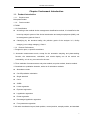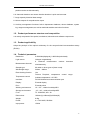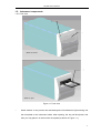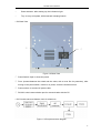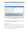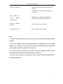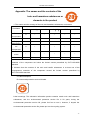
1
Operation Manual for
UT-6500
Microplate Reader
PLEASE READ THIS MANUAL CAREFULLY BEFORE OPERATION
3, Hagavish st. Israel 58817 Tel: 972 3 5595252, Fax: 972 3 5594529 [email protected]
MRC.VER.01-7.11
UT-6500 user’s manual
How to use UT-6500 user’s manual
Thank you very much for becoming the user of UT-6500 Microplate Reader.
Be sure to read this manual carefully before operating the instrument.
In order to obtain the best result, it is important for you to get familiar with the instrument and
its performance before clinic application.
The user’s manual is the operation instruction of MRC’s UT-6500 Microplate Reader. which
will show you the instrument specification, instrument installation, daily use, maintenance and
other aspects.
If you have any questions, please contact with the distributor.
Please keep all the packing materials for future storage, transport and return to factory for
repairing.
The instruments of different versions or configurations are featured with a little
different function.
Attention: Notes, tips, advices and recommendations are shown in italics to clear
differences.
Warning: The warning shall be strictly abided by in order to ensure that the instrument
may works normally and the test results may be correct and authentic.
Black letters are adopted for distinction.
Statement
MRC has the final interpretation of this instruction.
The iconographs provided in this instruction only act as examples, may not be entirely
consistent with the the actual show of the product, take the actual product as the priority, and
should not be used for other purposes. Without the written consent of MRC, any individual or
organization must not copy, modify or translate the contents of this manual.
Only meet all the following requirements, may MRC be considered to be responsible for the
product safety, reliability and performance, namely:
The installation, re-commissioning, expansion, improvement, and maintenance are all
conducted by the personnel approved by MRC company;
1
UT-6500 user’s manual
The product operation is carried out in accordance with this manual;
The related electrical equipments are in line with national standards.
Note:
The analyzer should only be operated by the professionals of medical inspection, or the
trained doctors, nurses or laboratory assistants.
Warning
If the end user can not establish a satisfactory maintenance/repair program, it may result
in some abnormal analyzer failure, and may endanger human health.
It should be guranteed that the analyzer must be operated under the conditions laid
down in the manual, if it is operated beyond these conditions, it may result in that the
analyzer can not operate normally, or the measurement results will be unreliable, and
may even damage the analyzer components as well as damage to personal security.
2
UT-6500 user’s manual
The main icons used in this instrument
Temperature limitation
It shows that the transport packages shall be kept at the
temperature limit.
Fragile, handle with care
The breakables are loaded in the transport packages, so place
them carefully and gently when carrying them.
Upward
To show that the correct position of the transport package
should be vertical upward.
Rain vulnerable
The package is rain vulnerable.
Stacking layer limit
The maximum stacking layers of the same packing, 8 means
the layer limit.
Biological contamination.
Note: Refer to the accompanying documents.
In Vitro Dignostic
3
UT-6500 user’s manual
Warnings and safety tips
Only in vitro diagnostic use, carefully read the following warnings before use, and must be
strictly adhered to them.
Some articles and materials used by certain test items have biological risk. When
operating the instrument, must wear protective clothing and glasses, and must lay down
the protective cover. (ELISA Cover Board).
Do not discard the used medical consumables discretionarily, it is should be handled as
the medical waste.
Pharmaceutical Affairs Law: it is prohibited to modify medical devices.
The instrument power cable ground wire should be earthed, in order to avoid electric
shock, the ground wire must be connected to ground.
The AC power must be stable, and it is prohibited to share power supply with the
appliances of high power. The instrument should be placed at the position easy to
disconnect the power.
In the area of unstable voltage, please use the UPS power to ensure the normal work of
the instrument.
When unplugging the power cable, please seize the plug itself, rather than the power
cable.
If the instrument is found to have smoke, smell or abnormal sounds, immediately turn off
the power, and contact the maintenance service center immediately.
After completing the test, must turn off the analyzer in accordance with the standard
program to prevent data loss.
When repairing or demolition of housing for other reasons, must cut off the power and
shutdown the mainframe.
When turning off the instrument, must ensure the switching key to be connected in place
rapidly to avoid damaging the system.
Must wear rubber gloves when conducting maintenance, and clean your hands after
4
UT-6500 user’s manual
each operation to avoid infection.
Do not allow hands or other parts of the body contact with reagents or patient samples, if
some wound parts contact with the patient sample accidentally, please promptly clean
and receive doctor examination.
After completing the microplate incubation, must clean out the moisture in the plate
botttom, otherwise, the inside parts may be corrode resulting in inaccurate test results.
This product is a desktop test instrument, there is no contraindication problem.
5
UT-6500 user’s manual
Contents
HOW TO USE UT-6500 USER’S MANUAL........................................1
THE MAIN ICONS USED IN THIS INSTRUMENT .............................3
WARNINGS AND SAFETY TIPS........................................................4
CONTENTS .......................................................................................6
CHAPTER I INSTRUMENT INTRODUCTION....................................9
1.1. Product introduction..................................................................................... 9
1.1.1. Product name .................................................................................................................... 9
1.1.2. Product model...................................................................................................................... 9
1.1.3 Classification............................................................................................................................ 9
1.1.4 Product Performance........................................................................................................... 9
1.2.
1.3.
1.4.
1.5.
Product performance structure and composition ....................................... 10
Product applicability................................................................................... 10
Technical parameters................................................................................. 10
Instrument components ..............................................................................11
1.5.1 Front view............................................................................................................................... 11
1.5.2 Back View............................................................................................................................... 12
1.5.3 Principle structure diagram (only for reference) ............................................................... 12
1.6. Operation principle..................................................................................... 13
CHAPTER II INSTRUMENT INSTALLATION ................................... 14
2.1
2.2
2.3
2.4
Instrument unpacking ................................................................................ 14
Environmental Requirements..................................................................... 14
Power Requirements ................................................................................. 15
Start Installation ......................................................................................... 15
2.4.1
2.4.2
2.4.3
Connect the instrument to the power supply............................................................... 15
External printer connection ............................................................................................ 15
Connecting the instrument with the computer ............................................................ 15
CHAPTER III SYSTEM LOGIN ........................................................ 17
3.1
3.2
3.3
3.4
Instrument serial number ........................................................................... 17
User Log .................................................................................................... 17
System Self-check ..................................................................................... 18
Logon Result.............................................................................................. 19
CHAPTER IV INFORMATION MANAGEMENT................................ 20
4.1
Patient Information..................................................................................... 20
6
UT-6500 user’s manual
4.2
4.3
4.4
User management ..................................................................................... 20
Basic Settings ............................................................................................ 21
Department management .......................................................................... 22
CHAPTER V ITEM SETTINGS ........................................................ 24
5.1
5.2
Measurement methods .............................................................................. 24
5.2 Calculation methods ............................................................................ 24
5.2.1
5.2.2
5.2.3
5.3
5.4
Absorbance Mode ........................................................................................................... 25
Qualitative calculation Cut-Off....................................................................................... 25
Quantitative Calculation ................................................................................................. 25
Basic item settings..................................................................................... 27
New item creation ...................................................................................... 30
CHAPTER VI SAMPLE TEST .......................................................... 31
6.1
6.2
6.3
6.4
6.5
6.6
Template Type ........................................................................................... 31
Measurement methods and calculation methods....................................... 32
The settings and selections of the testing process .................................... 32
Layout parameters settings........................................................................ 33
Select test items ........................................................................................ 33
Layout........................................................................................................ 33
6.6.1
6.6.2
6.6.3
6.6.4
6.6.5
6.6.6
6.6.7
6.6.8
6.7
6.8
6.9
6.10
6.11
6.12
6.13
Sample................................................................................................................................. 33
Blank .................................................................................................................................... 34
Negative control.................................................................................................................. 34
Positive control ................................................................................................................... 34
Threshold serum ................................................................................................................ 35
Standards ............................................................................................................................ 35
Quality Control .................................................................................................................... 35
Clear..................................................................................................................................... 35
Clear the whole plate ................................................................................. 35
Measurement............................................................................................. 35
Absorbance display ................................................................................... 35
Quantitative results display ........................................................................ 36
Qualitative result display ............................................................................ 36
Print ........................................................................................................... 36
Save .......................................................................................................... 36
CHAPTER VII RESULT VIEW.......................................................... 37
7.1
7.2
7.3
7.4
Test results................................................................................................. 37
Quality control information ......................................................................... 37
Calibration curve........................................................................................ 38
System Log................................................................................................ 39
CHAPTER VIII SYSTEM SETTINGS ............................................... 40
8.1
System time ............................................................................................... 40
7
UT-6500 user’s manual
8.2
8.3
System self-check...................................................................................... 40
Error alarm................................................................................................. 40
CHAPTER IX DATA MANAGEMENT ............................................... 42
9.1
9.2
Database Backup ...................................................................................... 42
Database recovery..................................................................................... 42
CHAPTERⅩ INSTRUMENT MAINTENANCE................................. 43
10.1 Cleaning the instrument............................................................................. 43
10.2 Instrument part replacement ...................................................................... 43
10.2.1 Fuse replacement ............................................................................................................ 43
10.2.2 The replacement of the halogen tungsten lamp.......................................................... 43
10.3 Simple Troubleshooting ............................................................................. 44
APPENDIX: THE NAMES AND THE CONTENTS OF THE TOXIC
AND HAZARDOUS SUBSTANCES OR ELEMENTS IN THE
PRODUCT ....................................................................................... 46
8
UT-6500 user’s manual
Chapter I Instrument Introduction
1.1. Product introduction
1.1.1. Product name
Microplate Reader
1.1.2. Product model
UT-6500
1.1.3 Classification
According to the medical device management classification method, it is classified as the
immunity analysis system of the clinical examination and analysis equipment (6840), and
its management grade is Class II.
Classifying by the electrical safety, the pollution grade of the analyzer is 2, facility
category (over voltage category): Class II.
1.1.4 Product Performance
1. Reagent is open, no specific restrictions.
2. Automatic measurement mode, except for the automatic sampling and plate-washing
function, the measurement, calculation, and results display can all be carried out
automaticlly, so it is very convenient for the user.
3. Three methods of measurements: end-point method, two-point method, kinetics method.
4. Quantitative or qualitative detection, with a lot of calculation methods:
Absorbance mode
Cut-Off qualitative calculation
Single standard
Curve
%ABS
Linear regression
Exponent regression
Logarithmic regression
Power regression
Percentage logarithmic regression
Four-parameter regression
5. 96-wells visualization layout, blank position, control position, sample position, and standard
9
UT-6500 user’s manual
position can be set discretionarily.
6. 8 channels detection can ensure that the detection is quick and accurate.
7. Large-capacity historical data storage.
8. Various outputs of comprehensive report.
9. Auxiliary management functions: built-in department database, doctor database, system
log, reagent management, as well as workload statistics and other functions.
1.2. Product performance structure and composition
It is mainly composed of the optical, mechanical, electronic and software components.
1.3. Product applicability
Adopt the principle of the optical colorimetry for the enzyme-linked immunosorbent assay
(ELISA).
1.4. Technical parameters
Resolution:
0.0001Abs(displayed), 0.0001Abs(calculated)
Light source:
Halogen tungstenlamp
Measurement channel:
8
channels
measurement
conduct
simultaneously
Sample type:
96-wells or other types of plate or strip
Wavelength range:
340nm ~ 900nm
Plate shaking function:
Yes
Temperature control
detection
Feature
Required,
temperature
control
range:
Ambient temperature +4C~50C
Interface:
RS-232 bidirectional communication port
Display :
External display
Print:
External printer
Working environment:
10 ~35 ; relative humidity≤85%
Storage environment:
-10 ~40 ; relative humidity≤85%
Fuse:
T3.15AL250V, Ф5 × 20
Dimensions:
186mm(L)×440mm(W)×220mm(H)
Weight:
9.0kg
Power:
a.c.110V-220V; 50/60Hz
Input power:
150VA
10
UT-6500 user’s manual
1.5. Instrument components
1.5.1 Front view
②
①
Hatch is closed
③
Hatch is open
Figure 1-1 Front view
①
Hatch window: it can prevent dust and background miscellaneous light entering into
the microplate or the instrument inside, when opening, the tray will be ejected, and
then you may place in or take out the microplate (as shown in Figure 1-1).
11
UT-6500 user’s manual
①
Power indicator: after starting up, the indicator is light.
①
Tray: to carry microplate, with automatic clamping feature.
1.5.2 Back View
②
④
①
③
Figure 1-2 Back View
① Power Switch: Open or close the power.
② Fuse: (located between the switch and the outlet, with a cover film for protection), after
turning on the power switch, if there is no power, check the instrument fuse.
③ Power socket: to connect AC power cable.
④ RS-232: serial communication port for communication with the PC.
1.5.3 Principle structure diagram (only for reference)
Figure 1-3 Principle structure diagram
12
UT-6500 user’s manual
1.6. Operation principle
Connect UT-6500 and computer with RS-232 cable firstly, switch on the instrument, and then
run software of UT-6500 in computer.
13
UT-6500 user’s manual
Chapter II Instrument Installation
2.1 Instrument unpacking
Unsealing the instrument’s package and remove the materials for transport. Save the packing
box and the packaging materials well, for your convenience in the future of re-packaging the
instrument.
Take out the instrument from the box.
Take away the packaging materials, and take out the instrument from the plastic packaging
bag.
Check the items in the box and confirm that the following items are within the box:
UT-6500 Microplate Reader mainframe
User’s Manual
Packing List
Certification of inspection
Accessory.
Note: If the items are inconsistent with the packing list or have any defects, please
contact with the supplier.
2.2 Environmental Requirements
In your workplace, select a place without direct sunlight. The surface of the worktable should
be flat, with enough space for placing UT-6500 Microplate Reader and PC computer. The
front edge of the instrument should be close to the table edge. Keep the worktable free of big
shock (if there is a centrifuge placed on the worktable).
Note: The instrument working environment temperature should be 10 -35 , and the
relative humidity should be less than 85%. The instrument should be placed at
the place with excellent ventilation.
In order to ensure the normal operation of the instrument, it is prohibited to place the
instrument in the following places:
14
UT-6500 user’s manual
A place with extreme temperature changes
A place of particular heat or special cold
A place of a large number of dusts
A place close to the magnetic field of electromagnetic devices
2.3 Power Requirements
a.c.110V-220V
50/60Hz
150VA
2.4 Start Installation
2.4.1
Connect the instrument to the power supply
1) Plug one end of the power cable into the power outlet of the instrument.
2) Plug the other end of the power cable into an AC power outlet.
Warning:
●The AC power supply must be well grounded (zero ground voltage <5V).
●The AC power must be stable and it is prohibited to share power supply with the
appliances of high power.
●When unplug the power cable, please seize the plug itself, rather than the power
cable.
●If the instrument is found to have smoke, smell or abnormal sounds, immediately
turn off the power, and contact the supplier.
2.4.2
External printer connection
This system supports most types of the USB interface printers and parallel interface printers.
Please connect the printer to the PC host which is connected with the instrument referring to
the user's manual of printer, and carry out the installation.
2.4.3
Connecting the instrument with the computer
1) Turn of the power of the instrument and computer.
2) Connect both ends of the serial cable to the RS232 serial ports of the instrument and the
15
UT-6500 user’s manual
computer host respectively.
Note: After connecting the instrument and computer through the serial cable, turn on
the instrument power, and then run the program in computer.
16
UT-6500 user’s manual
Chapter III System Login
3.1 Instrument serial number
If it is the first time to use the instrument or the serial number is blank, the system will ask the
user to enter the serial number on the rear part of the instrument correctly.
As shown in Figure 3-1:
Figure 3-1 Instrument serial number
If the user has entered the serial number, the dialog box will not pop up in the next use.
Entering the serial number makes us provide maintenance services for users more quickly
and fast.
3.2 User Log
After the users enter the serial number, the system will pop up a user login window. As shown
in Figure 3-2:
17
UT-6500 user’s manual
Figure 3-2 User Logon
Select the user’s name from the list box, enter the password in the password box, and then
click “Enter” button, if the user’s name and password are correct, the system will enter into
self-checking state, otherwise the system will prompt the user that the login is failure. Click
“ESC” button to exit the system.
User’s authority includes two kinds: administrator and normal user.
3.3 System Self-check
If the logon is correct, the system will enter into self-checking state, during the self-checking
period, the system will detect whether the serial port is available automatically, if not available,
the system will prompt the user to check whether the connection with the instrument is
correct, if available, the system will execute the self-checking operation. Self-checking
window is shown as Figure 3-3
18
UT-6500 user’s manual
Figure 3-3 System Self-check
After completing the self-check, the system will enter the main menu interface.
3.4 Logon Result
If the self-check of the system is successful and the logon is conducted by an administrator,
all the functions in the main menu are available, if the logon is conducted by a normal user,
some of the menu can not be operated, if the self-check of the system is failure, the user only
can operate “Information management” and “View” menu, its interface is shown as Figure
3-4:
Figure 3-4 Main menu
19
UT-6500 user’s manual
Chapter IV Information Management
Information management includs four parts: patient information, user management, basic
settings, and department management.
4.1 Patient Information
Including the patient's basic information input, form information input, inquiry, as well as
deleting or adding the items conducted by the patient. As shown in Figure 4-1:
Figure 4-1 Patient Information
4.2 User management
Including adding users, deleting users, changing passwords and modifying the authority.
User authority is classfied as two kinds: administrator and normal user. Only the
administrator user has the authority to add users, delete users, and modify the authority.
Normal user only has the authority to change the password.
Adding the user interface is shown as Figure 4-2:
20
UT-6500 user’s manual
Figure 4-2 Adding user
4.3 Basic Settings
Include five parts: the hospital information, doctor information, division information, as well as
ward information and diagnostic information.
In which, the doctor information is shown as Figure 4-3:
Figure 4-3 Doctor Information
Doctor information includes doctor of examination, doctor of submission, and doctor of check.
21
UT-6500 user’s manual
4.4 Department management
Include workload statistics and reagent information. Workload statistics is used by hospital to
verify the doctor’s work at a certain stage. Through the workload statistics, the number of the
plates, items and patients conduceted by a doctor in a certain period can be inquired.
The function of the workload statistics is shown as Figure 4-4:
Figure 4-4 Workload statistics
Reagent information includes adding reagent, delecting reagent, as well as modifying reagent
and other functions.
22
UT-6500 user’s manual
Figure 4-5 Reagent information
23
UT-6500 user’s manual
Chapter V Item Settings
In the main menu, click on the “Item_Set” under the “Item” or directly click on the “Item_Set”
on the toolbar, then you can enter the Item Settings dialog box. As shown in Figure 5-1.
Figure 5-1 Item settings
In this interface, you can add, modify, or delete items. The item properties mainly include
basic item information, standard settings, quality control settings, and the options of validity
formulas.
100 items are permitted to be set at the most. The user pre-set items will be displayed at the
left list of the window.
5.1 Measurement methods
Measurement methods include end-point method, two-point method and kinetics method
5.2 5.2 Calculation methods
UT-6500 Microplate Reader supports various of different calculation methods, which can be
divided into the following three categories.
24
UT-6500 user’s manual
5.2.1
Absorbance Mode
Directly measure and output the sample absorbance.
5.2.2 Qualitative calculation Cut-Off
Cut-Off threshold formula: Cov = X×NC+Y×PC+Z×CR+Fac
Where NC is the negative control absorbance value, PC is the positive control absorbance
value, and CR is the threshold serum absorbance value. X, Y, Z, and Fac are the formula
coefficients, which should be input by users according to the reagent instructions, at the
same time all other forms of qualitative formulas can be transformed into this form. For
example: when sample OD/negative control OD ≥ 2.1, it is positive, then X = 2.1, Y=0, Z=0,
Fac=0.
The calculation method of Cut-Off can choose single-threshold and double-threshold.
The results of qualitative calculation will be expressed by the ratio of the sample absorbance
and the Cut-Off threshold, and the unit is s/co.
5.2.3 Quantitative Calculation
1). Single standard: It needs to set a standard, taking the connecting line between the origin
point and the standard point as the calibration curve (The abscissa represents concentration,
the ordinate represents the absorption, the same below), single-point calibration must set
blank to calibrate 0 point.
Absorbance
Concentration
2) Curve: Allow to set 2-8 standards, taking the connecting line between each standard point
(It should be a non-linear of monotonic increase or decrease) as the calibration curve:
25
UT-6500 user’s manual
Absorbance
Absorbance
Concentration
Concentration
If the absorbance of the standard is not shown as monotonic increase or decrease, then the
calibration result is wrong:
Absorbance
Concentration
3) %ABS: Allow to set 2-8 standards, the maximum absorbance value of the standard is
defined as 100%, the absorbances of other standards and the samples under test are all
represents with the ratio percentage with it. The calibration method is the same with
non-linear regression.
4) Linear regression: Allow to set 2-8 standards, through these standard points to regress out
one line Y = kX + b , as the calibration curve:
Absorbance
Concentration
5) Exponent regression: Allow to set 2-8 standards, through these standard points to regress
out one exponential curve Y = ke
bX
as the regression calibration curve, and the absorbance
value of each standard must be greater than 0.
If we take the logarithmic absorbance value( Y ′ = LnY ), then the index regression can be
transformed into one form of linear regression: Y ′ = k ′X + b ′
26
UT-6500 user’s manual
6) Ogarithmic regression: Allow to set 4-8 standards, through these standard points to
regress out one logarithmic regression curve Y = kLnX + b as a calibration curve, the
concentration value of the standard must be greater than 0.
If we take the logarithmic concentration value( X ′ = LnX ), then the logarithmic regression
can be transformed into one form of linear regression Y = kX ′ + b :
7) Power rgression: Allow to set 2-8 standards, through these standard points to regress out
b
one power regression curve Y = kX as the calibration curve, the absorbance values and
the concentration values of all the standards must be greater than 0.
If we take the logarithmic values of the concentrations and absorbances( X ′ = LnX ,
Y ′ = LnY ), then the power regression can be transformed into one form of linear
regression: Y ′ = k ′X ′ + b ′
8) Percentage logarithmic regression
Percentage logarithmic regression allows setting 4-8 standards, and the concentration of
each standard must be greater than 1.
9) Four-parameter regression
Four-parameter regression allows to set 4-8 standards, you can input the corresponding
concentration values according to the relavant reagent instructions, detect the absorbance
value of the standard solution by instrument, and determine the regression curve with
Gauss-Newton iteration method.
5.3 Basic item settings
As shown in Figure 5-1, the item settings include the following parameters:
Item name: This part must not be empty, and pay attention to not repeat with the name
already existed.
Manufacturer: you can choose from the list box according to the reagent used, can also be
empty.
27
UT-6500 user’s manual
Wavelength: select from the list, notice that the dominant wavelength and the secondary
wavelength can not be repeated.
Measurement method: select from the list box.
Calculation method: select from the list box.
Double samples: If you choose double samples, when conducting plate layout, the
adjacent wells will be automatically set as the repeated wells, and the system will take
the average value of the absorbances of the two wells for calculating.
Reference lower limit, upper limit: Mainly used as the reference range of the test results.
Delay time, test time, and factor are mainly used for the Kinetics method settings.
Note: In accordance with the different types of calculation methods, the parameters of
item settings may also be different.
1) The quantitative calculation - you must set the standard information for the item:
Input according to reagent instruction:
The number of the standards
Select 1-8 standards.
Double standards
If you choose double-standards, when conducting plate layout, the adjacent well will be
automatically set as the repeated well, and the system will take the average value of the
absorbances of the two wells for calculating.
Standard concentrations
Note that the order of the standard concentration must be monotone.
2) Qualitative calculation: Cut-Off formula settings window:
Input into the item settings dialog box according to the reagent instruction.
Cut-Off formula factor
The qualitative formulas of various reagents may be expressed in different forms, such as
S/N, (N-S)/N, etc., but they can be converted to the form of S/(X*N+Y*P+Z*C+Fac)totally.
If you choose double-threshold, you can enter two Cut-Off formulas.
28
UT-6500 user’s manual
Negative control, positive control, as well as the absorbance range of threshold
serum
If the control absorbance exceeds the upper limit or the lower limit, the calculation should
be conducted in line with the upper limint or lower limit respectively. For instance, there
are some reagents require that if the negative control is less than 0.05, it should be
calculated as 0.05, then the lower limit of the negative control should be set as 0.05.
Control
It can be set discretionarily, but the control quantity of each test item can not exceed 12,
and take the average value of all the control absorbances for calculating.
3) The positive and negative judgement settings
In this window, enter the critical values to determine negative and positive, under the
absorbance mode, the critical value is the absorbance value; under the Cut-Off mode, the
critical value is the ratio between the sample and the threshold; under the quantitative
calculation mode, the critical value is the concentration value. The qualitative methods are
divided into three categories:
Positive threshold mode
Negative value <Negative critical value, Positive value≥Positive critical value, the area
between the two parts is the gray area, the samples in this range is doubtful.
Negative threshold mode
Negative value>Negative critical value, Positive value≤Positive critical value.
Negative or positive don’t need to be judged.
In quantitative mode, select “None”
4) Quality control settings
Quality control methods include ELISA (self value), ELISA (set value), and the immdiate
method. ELISA method has four kinds of conditions to determine whether the quality control
data is out of control, either single item settings or group settings can be selected according
to the condition.
5) Judgement of validity
29
UT-6500 user’s manual
Judgement of validity requires the users to select from the formula library for each item.
Formula is the key point of the judgement of validity. The judgement of validity interface is
shown as Figure 5-2.
Fugure 5-2 Formula library
Note: Users must enter a reasonable formula. Otherwise, the system will generate
unnecessary warnings during the measurement process.
5.4 New item creation
Click the “Add” button to add new items. If the item quantity has already exceeded 100, it will
not be able to create a new item, and the system will prompt “the item quantity is full”. The
operation of new item creation is the same with the steps to alter the old items, pay attention
to that the name of the new items can not repeat the existing items. Otherwise, the system
will warn “The item name is exist or some fields are invalid!”.
30
UT-6500 user’s manual
Chapter VI Sample Test
Sample test interface is shown in Figure 6-1.
Figure 6-1 Sample test interface
Sample test menu mainly includes the selections of template type, test mode, calculation
method; settings of set plate parameter, plate moving parameter and the microwell settings
on the Microplate. Microplate settings mainly include settings of sample type and the select of
blank mode.
6.1 Template Type
Template type mainly includes two types, new template and existed template. If new template
is secleted, the information on the Microplate is empty. The type of user selectsion sample is
the same with that of sample, using mouse to click the microplate can perform plate
arrangement. If the existed enzyme label plate is selected, click “Test” button to perform
measurement.
31
UT-6500 user’s manual
6.2 Measurement methods and calculation methods
Measurement methods include end-point method, two-point method, and kinetics method.
After selecting the measurement method, the appropriate calculation method can be selected
from the list box, and then sample information can be set for the Microplate.
6.3 The settings and selections of the testing process
The testing process includes three parts, that is, creating a new template, deleting a template,
and an established template created by user. After choose “New” to add a new template of
the testing process for the item settings, select the newly created template, if the item has the
temperature settings, the incubating position of the instrument will start to heat, when the
temperature reaches the requirement, the test will be executed, if there is no temperature
settings, directly select the test button to start the test.
After creating a new template, the system will enter the testing process settings interface, as
shown in Figure 6-2.
Figure 6-2
Select the appropriate steps and execute the corresponding settings, clink on “Add” to add a
step, and then the newly added steps and the implementation order will be displayed in the
left view. If need to delete or modify some steps, select the specific test step and clink on
32
UT-6500 user’s manual
“Delete” and “Amend” to complete the operation. At last, enter the template name and clink
on “Save program”, now, the test step settings is completed.
6.4 Layout parameters settings
Layout parameters include the following settings:
Layout direction: row or list.
Start No.
Start well and End well
Input start sample number (1-999) and start well position (row number and list number), end
well position(row number and list number), click “OK” button. All wells of the whole plate are
set as samples according to current item. Sample number of start well is inputted start
sample number and sample number of end well is inputted end sample number. Sample
number of other well positions increase successively according to set plate direction. When
‘Delete Plate’ function is used, all items and wells that have been set will be cleared. If want
to set standard or control, please operate after deleting all.
6.5 Select test items
As for UT-6500 Microplate Reader, the same plate only can be set one test item.
6.6 Layout
UT-6500 Microplate Reader allows the user to set the well-position discretionarily within the
plate of 96-well. At the top of the window is the “Set sample type” switch, the users need to
select the well-type firstly, and then click on the well-pisition.
The mark symbol of the well-position:
Sample: 1-999
Blank: BK1 - BK12
Negative control: NC1 - NC12
Positive control: PC1 - PC12
Threshold serum: CR1 - CR12
Standard: SD1-SD8
Quality Control: QC
6.6.1 Sample
When the user clicks on the well-position to be set as the sample, the sample number will
33
UT-6500 user’s manual
increase orderly from 1 and display at the well-position automatically. If you want to modify
the sample number, just double-click the well-position:
Re-enter the sample number in the pop-up window, if the sample number already exists, the
system will prompt that “The same No. is exist!”, the modification is invalid. The allowable
sample number for UT-6500 Microplate Reader is 1-999.
6.6.2 Blank
Blank well is used to conduct absorbance zero setting in the item test, that is, all the
absorbances of other wells need to subtract the absorbance value of the blank well.
According to the requirements of different test items, the user may choose whether to set a
blank or not.
Blank methods include None blank, One blank, Many blank, List blank, Row blank ,Average
list blank,and Average row blank. In which, If the user selects the “Row blank” or ”Average
row blank”. just click the row mark at the left of the simulative microplate. If the user selects
the “List blank” or “Average list blank”, just click the list mark on the upper of the simulative
microplate.
Saving and application of old blanks the test results of the blank well will be saved
automatically, if you do not re-set the blank of the same item in the following test, the system
will use the old blank to calculate automatically.
6.6.3 Negative control
Be effective only in the item that calculation method is Cut-Off. According to Cut-Off formula,
user must set negative control except for the condition that negative control coefficient is 0.
Each item is permited to set 12 negative controls at the most.
During the item-testing period, the absorbance of the control well and the corresponding
calculation results of Cut-Off value will be saved automatically, as for the same item in the
following test, if you do not reset the control, the system will use the old Cut-Off value to
calibrate.
6.6.4 Positive control
It is similar with the negative control settings.
34
UT-6500 user’s manual
6.6.5 Threshold serum
It is similar with the negative control settings.
6.6.6 Standards
It will be valid when the item settings need to calibrate the standards. If the old standards for
the item already exists, the user may choose not to set the standards (using the old
standards for calibration), or reset all the standards, but it is not allowed to only set part of the
standards. When the user clicks the standard wells in turn, the system will also mark it as
SD1, SD2 ... in turn.
After completing the settings of the standards, if the user clicks again, the system will prompt
"The number of standards is full". If the user begins to test or add a new item when the
standard settings are not completed, the system will prompt "The number of standards is
enough”.
6.6.7 Quality Control
The number of quality control substance is not limited.
6.6.8 Clear
If you need to modify the pre-set well-position, press the clear switch, after clicking clear
switch, user can clear all set well position of current item, and then re-set as required.
6.7 Clear the whole plate
Remove all the pre-set items and the wells.
6.8 Measurement
Click "Test” button, the system will pop-up a dialog box of Measurment.
Press stop button to cancel the current test. “Move Out” and “Reset” buttons can control the
microplate moves out and reset respectively. During the testing period, the two buttons are
unavailable.
6.9 Absorbance display
When completing the plate running test, the system will display the absorbance automatically.
In some special case, users may need to modify the absorbance value of the sample or the
35
UT-6500 user’s manual
standard measured by the experiment, and you can double-click the well-position to be
modified:
Just re-enter the absorbance value into the pop-up window. During the calibration period, if
the calibration has an error, the system may prompt "Item xxx calibration has an error." The
possible reasons include: the absorbance is 0 or negative value, the linear regression has an
error, as well as the absorbance-concentration curve of the standards is not monotonic, and
so on.
6.10 Quantitative results display
Click on “Quantity” to display the values of the quantitative results.
6.11 Qualitative result display
Click on “Quality”to display the values of the qualitative results, if the test item does not need
the qualitative results, it will only display the sample number.
6.12 Print
Click “Preview” button, all the plate results of the current test (including the well-position, test
item, sample number, absorbance, quantitative results, and qualitative results) will be printed
based on the layout format and the sub-items.
Note: Before printing the results, should save the results firstly.
6.13 Save
Click “Save” to save the test results of the present plate into the database for future
observation.
36
UT-6500 user’s manual
Chapter VII Result View
Result View includes test results, quality control information, calibration curves and the
system log.
7.1 Test results
Experiment results are the primary information of this system, while enquiry to the results of
patients and printing of main reports are located in this window. Test result window is shown
as Figure 7-1:
Figure 7-1 Test results
The window includes four parts, “Report by plate”, “Report by item”, “Report by patient” and
“Report by collection”. The frontal 3 parts of results can be inquired or printed based on the
current day, within one week, or other optional time completely.
7.2 Quality control information
Include the results inquiry for a certain batch number of each item within a certain period. The
quality control information includes the maximum, minimum, mean, SD and CV values of the
quantitative and qualitative results within a certain period. The dialog box is shown as Figure
7-2:
37
UT-6500 user’s manual
Figure 7-2 Quality control information
Select the item required in the Item Name list box, select the batch number in the Batch
Number list box, and then select the desired inquiry time. Click “Search” button.
7.3 Calibration curve
The calibration curve is mainly used to check the calibration results of various items. The
dialog box is shown as Figure 7-3:
38
UT-6500 user’s manual
Figure 7-3 Calibration curve
7.4 System Log
The system log mainly records the login user’s name, login time, exit time and exit reason.
Inquire the logon situation of the user within a certain period of time. The dialog box is shown
as Figure 7-4:
Figure 7-4 System log
39
UT-6500 user’s manual
Chapter VIII System Settings
System settings include system time, system self-check, and error alarm.
8.1 System time
The system time is mainly used to view or modify the system time and date.
8.2 System self-check
As shown in Figure 8-1. The system self-check is mainly used to test the instrument
parameters, such as the light intensity AD value of various wavelengths of the instrument, the
ABS value and light intensity AD value of the selected wavelength.
Figure 8-1 System self-check
8.3 Error alarm
Mainly record the warning condition of the instrument, as shown in Figure 8-2.
40
UT-6500 user’s manual
Figure 8-2 Error Alarm
41
Chapter IX Data Management
9.1 Database Backup
Database backup is a simple backup of the entire database, the dialog box is shown as
Figure 9-1.
Figure 9-1 Database backup
9.2 Database recovery
Database recovery refers to recovering the previous backup database.
As shown in Figure 9-2.
Figure 9-2 Database Recovery
42
UT-6500 user’s manual
ChapterⅩ Instrument Maintenance
UT-6500 Microplate Reader is a sophisticated clinical analyzer, so in order to maintaining the
instrument in a good condition, you must do the routine maintenance work well. The
maintenance of UT-6500 Microplate Reader is very simple, but it must be conducted
carefully.
Warning: The instrument maintenance must be executed by the professionals, when
repairing or demolition of housing for other reasons must cut off the power and
shutdown the mainframe.
10.1 Cleaning the instrument
Keep the instrument working environment clean.
Neutral detergent and wet cloth can be used to clean the surface of instruments.
LCD display must be cleaned with a soft cloth.
Warning: Do not allow any solvents, fats and oils, or corrosive substances contact
with the instrument.
10.2 Instrument part replacement
10.2.1 Fuse replacement
1) Turn off the power switch.
2) The fuse is installed in the fuse box which is located at the rear of the instrument and close
to the power switch. Open the box cover, and then replace the fuse with the same
specification.
Fuse specification: T3.15AL 250V.
3) Close the fuse cover, restart the machine.
Warning: Must use the fuse with above specification.
10.2.2 The replacement of the halogen tungsten lamp.
When the halogen tungstenlamp is damaged, execute the following steps to replace it:
43
UT-6500 user’s manual
1) Turn off the power switch, open the right lower cover of the instrument.
2) Gently press and open a flexible clasp when the lamp is not hot.
3) Remove the lamp from the holder, unplug the blub wire.
4) Connect the new bulb with the blub wire, and then put the new bulb into the holder.
5) Clamp the bulb with the elastic clasp.
6) Close the cover, restart the machine.
10.3 Simple Troubleshooting
Phenomena
Reasons
Solutions
Microplate Reader
The power is not
Check power on or not
can not start up
normal
Check whether the power plug is loose
Check the fuse
Check the voltage
Bulb does not light
The on-off interval
Shutdown for more than 30 seconds, and
is too short
then restart
The bulb power is
not normal
The bulb is
damaged
The
light
is
too
strong
The
light
is
too
Check the power before replacing the bulb
Replace the bulb
The filter is not
Check whether the filter and filter wheel is
installed correctly
installed correctly
The bulb is
Replace the bulb
weak
damaged
Filter wheel has no
The filter wheel has
Open the cover, and check whether the
reposition signal
a failure
positon of the sensor is correct
Microplate can not
Driving motor has a
Open the cover, and check whether the
move
failure
driving motor rotates.
Printer can not start
up
The printer power is
not normal
Check whether the power plug connection is
loose
Check the ON/OFF button
44
UT-6500 user’s manual
Printer can not print
Check whether the type of the printer is set
correctly
Check whether the printer cable is properly
connected
Color fading, the
overall
printing
quality declines
Printer is jammed
by paper
Other printer faults
Replace the ink cartridge, clean the print
head (see the printer user's manual)
(See the printer user's manual)
(See the printer user's manual)
Note:
1. If there is an error that you can’t solve or an error recurred, please contact with the
supplier.
2. As for the different version of the instrument, its configuration may be changed
slightly, these changes are made under the premise of not affecting the performance
and use of the instrument, please feel free to use it.
3. In order to keep the security of the user’s data, we shield the remote service
function of the instrument and take this function as optional.
4. If the accessory needs to be replaced, please contact with the manufacturer or
provided by the agent.
45
UT-6500 user’s manual
Appendix: The names and the contents of the
toxic and hazardous substances or
elements in the product
1. The names and the contents of the toxic and hazardous substances or elements
The toxic and hazardous substances or elements
Part Name
Built-in
Pb
Hg
Cd
Cr(
(VI)
)
PBB
PBDE
×
○
○
○
○
○
Shell
×
○
○
○
○
○
Display
×
○
○
○
○
○
×
○
○
○
○
○
○
○
○
○
○
○
×
○
○
○
○
○
circuit board
Opto-electro
nic
components
Internal
e-wire
Accessories
○: indicates that the contents of the toxic and harmful substances in all the homogeneous
materials of the component are below the limited content prescribed by SJ/T11363-2006
standard.
×: indicates that the contents of the toxic and harmful substances in at least one of the
homogeneous materials of the component exceed the limited content prescribed by
SJ/T11363-2006 standard.
2. Label Description
Environmental protection service life label.
Label meanings: This electronic information product contains certain toxic and hazardous
substances, and the environmental protection service life is 20 years, during the
environmental protection service life, please feel free to use it, however, if beyond the
environmental protection service life, please put it to the recycling system.
46