1
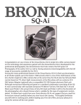
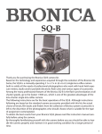
ETRSi
Congratulations on your choice of the Zenza Bronica ETRSi single lens reflex camera.
The ETRSi has been developed on the basis of the technology and experience gained with
the Zenza Bronica ETRS and is between the lens leaf shutter type single lens reflex camera
which provides full flash synchronization at all shutter speeds. When used together with
the exclusive SCA386 System Adapter (optional) in combination with specified electronic
flash units, it also has full auto-flash control based on TTL direct light measurements made
at the film plane. Used in combination with the newly-developed AE-III Prism Finder E, there
is also switching from full-area average metering to spot metering, as well as AE lock.
Although the following instructions are based on the standard ETRSi combination consisting of the ETRSi main camera body with the standard Zenzanon-PE 75mm lens, Film Back Ei
120 and Waist-Level Finder E, the choice of lens, film back and finder is, of course, left completely to the discretion of the user to suit picture taking needs.
1
Contents
Specification on the ZENZA BRONICA ETRSi
Parts of the ZENZA BRONICA ETRSi
1.
2.
3.
4.
5.
6.
7.
8.
9.
10.
11.
12.
13.
14.
15.
16.
17.
18.
19.
20.
21.
22.
23.
24.
25.
26.
27.
28.
29.
30.
Loading the Battery
Battery Check
Attachment and Removal of Film Back
Construction of Film Back
Film Loading
Film Type Indicator Frame
Film Advance and Shutter Cocking
Exposure Counter
Film Unloading
Setting the Shutter Speed Dial
Shutter Release Button
Time(T) Exposure
Exchanging Lenses
Interchanging Finders
Waist-Level Finder and Interchanging Magnifiers
Setting the Aperture
Focusing Adjustment
Distance Scale and Depth of Field Scale
Infrared Photography
Flash Photography
Multiple Exposures
Mirror Lock-Up
Interchanging Focusing Screens
Attachment of the Neck Strap
Facts About the Battery
Pointers on Shooting
Care and Maintenance
Depth and Field Tables
Interchangeable Lenses
Accessories for Increasing Versatility
Page
3, 4
5
6
6
7, 8
8
8, 9, 10
11
11
11
12
12
13
14
14
15
15, 16
16
17
17
17, 18
18, 19
19
20, 21
21
22
22, 23
23
23, 24
25
26, 27
27
2
Specifications of the ZENZA BRONICA ETRSi
Type
4.5 x 6cm format lens shutter single lens
reflex camera, with interchangeable lens, film
back, finder and focusing screen systems
Frame Size
42 x 55.1mm (side/length ratio of 1:1:31
closely matches standard paper and reduction sizes.
Film
120 roll film (15 exposures); 220 roll film (30
exposures); 135 cartridge loaded film; and
Polaroid Land pack film.
Standard Lens
Zenzanon-PE 75mm F2.8 lens, interchangeable type; 6 elements in 5 groups; multi-layer
anti-reflection coated; 49.7º angle of view;
F22 minimum aperture; 60cm minimum
focusing distance; and helical focusing.
Filter Size
62mm diameter for 40-250mm lenses and
95mm for 500mm lens.
Lens Mount
Exclusive four claw Bronica ETR bayonet
mount.
Lens Diaphragm
Fully automatic instant reopening diaphragm
action; equal-distance aperture scale graduations; depth of field previewing.
Shutter
Electronic control SEIKO #0 between-lens leaf
shutter: shutter speeds 8 to 1/500 sec. plus
B(bulb) and T(time); intermediate settings not
possible; mechanical control setting of 1/500
sec.
Film Winding
Film winding crank; one complete forward
revolution or ratcheted winding action.
Mirror Lock-Up
Multiple Exposure
Possible with mirror lock-up lever
Possible with multiple exposure lever; red
warning sign in finder.
3
Specifications of the ZENZA BRONICA ETRSi (con’t)
Film Back
Daylight loading interchangeable type; exclusive film back for 120, 220 and 135 roll film
and Polaroid Land pack film
Finder System
Interchangeable finder system; 94% of actual
field of view (remains unchanged with different finders); choice of four optional finders;
Waist-Level Finder E, AE-II Finder E, Rotary
Viewfinder E and Prism Finder E.
Focusing Screen
Interchangeable type; standard screen has
matte spot.
Flash Synchronization
X-setting (up to 1/500 sec) ; auto-flash control
based on direct light measurements at the
film plane is possible with optional SCA
System Adapter.
Battery Checking
Red-colored LED light up within screen area
when battery check button is depressed, if
there is sufficient power; also doubles as
shutter closing signal.
Battery
Single 6-volt silver oxide or alkaline-manganese battery; also powers AE-II Finder E,
when attached.
Dimensions
92( wide) x 87 ( high) x 69 (long)mm ( ETRSi
main body only)
92( wide) x 107( high) x 165 (long) mm (with
standard lens Film Back Ei 120 and WaistLevel Finder E)
Weight
480 grams (ETRSi main body only; without
battery)
1,285 grams (with standard lens, Film Back Ei
120 and Waist-Level Finder E; without battery.)
4
Parts of the ZENZA BRONICA ETRSi
Aperture ring
Flash synch socket
Focusing ring
Distance scales
Depth of field scale
Lens alignment dot
Waist-level finder
Focusing
hood/magnifier catch
Shutter speed
dial
Shutter speed
scale
Magnifier
Finder release button
Shutter speed
dial index
Back cover release
button (left)
Shutter release button
Safety lock index
(of shutter release button)
Back cover release
button (right)
Exposure counter
Lens release button
Depth of field
preview lever
Battery check button
Film winding crank
Multiple exposure lever
Dark slide slit
Mirror lock-up lever
Film plane mark
Film back
widning crank
Neck strap stud
Cable release socket
Shutter release connection
(for Motor Winder Ei, Motor driveE and Speed grip E)
SCA connector
Spool holders
Film back release button
Neck strap stud
Contacts (for Motor Winder Ei, and Motor Drive E)
Flash synch contact
Time (T)
exposure lever
Setscrew (for time
exposure lever)
Film type
indicator frame
Tripod mounting shoe
Tripod socket
(1/4” screw)
Battery chamber cover
Battery chamber button
5
1. Loading the Battery
The electronically-controlled speeds of the shutter will not work without loading the battery. One alkaline-manganese or one silver-oxide battery of 6 volts should be used.
The shutter will be mechanically controlled when the battery is not loaded, exhausted or
when it is loaded with its polarity marks reversed. It will then be released at 1/500 sec,
regardless of the setting on the shutter speed dial. Time exposure is an additional mechanical speed, accessible by a lever (A/T) on the lens.
* The batteries noted may be obtained at any photographic equipment or electrical appliance shop.
A. Depress the battery chamber button with your finger and, at the
same time, move the battery chamber cover in the arrow-indicated
direction. The cover will come off easily.
* When loading the battery, be sure to leave the battery removal ribbon extending out, for convenience in removing the battery the next
time.
B. Coincide the plus (+) and minus (-) marks on the battery with similar polarity indications in the battery chamber. Then, push in the negative end of the battery first and follow with the positive end.
C. Insert the BATTERY end of the battery chamber cover which also
has a mark coinciding to that on the body. Then move the cover in
the other direction (opposite to the arrow indication) until it locks in
place.
2. Battery Checking
If a red-colored battery check LED lights up in the left-rear corner (of
the screen area) when the battery check button is pressed, the battery is loaded properly and there is sufficient power for electronic
operations.
* If the LED does not light up, (1) the battery is not loaded properly or
(2) it is completely drained.
6
3. Attachment and Removal of Film Back
The film back is a film chamber that can be attached or detached freely, this permitting free
exchange of film types even during shooting sessions.
The camera main body and film back are fully coupled, upon connection. Therefore, always
turn the film winding crank completely one time, upon attaching the film back. If winding is
not possible, all preparations for taking the picture have been completed. But, if winding is
possible, rotating the film winding crank until it stops will automatically take care of the
incomplete action, whether uncocked shutter or film not advanced. Thus, it's always possible
to choose the film type most suited for the shot, even midway in the roll.
* Make full use of the interchangeable film back.
1. Color and black and white, in different film speeds, can be shot, as required.
2. Continuous shooting is possible if sufficient preloaded film backs are available.
3. Don't waste unsuitable film used in a previous session but simply load up a new film
back with the required film type.
4. Using a Polaroid Land Pack Film Back will provide an instant color or black and white picture, used typically for checking the lighting and/or composition before taking the actual
photograph.
* Choose film backs to match your photographic requirements, as various types and formats
are available optionally.
5. The film chamber that can be attached or detached freely, thus permitting changes in
film types even in mid roll. The camera body and film back are fully coupled upon connection. This means that the back and body communicate their state of readiness to each other,
and prevent accidental double exposures, or blank frames.
After attaching the film back, wind the crank. If winding is not possible, all preparations for
taking the picture have been completed. But, if winding is possible, the wind will automatically take care of any incomplete action, whether uncocked shutter or film not advanced.
Thus, any back can simply be attached to the body without need for checking the body, or
back for their state of readiness.
A. To attach the film back to the main body, simply insert the latches
at the upper end of the film back into the attachment openings at
the upper end of the main body. Then, press the lower end of the film
back against the main body until it locks securely.
* The dark slide must be withdrawn from its slit, upon attachment of
the film back to the main body, as otherwise the shutter cannot be
released.
7
3. Attachment and Removal of Film Back
(con’t)
B. To remove the film back from the main body, insert the dark slide
into the dark slide slit, as illustrated, with the mark on the dark slide
at the top end. Push it all the way in.
* There is danger of the film back accidentally becoming detached
from the main body, should the dark slide be left in its slit while the
camera is being carried. Therefore, make it a rule to withdraw the
dark slide promptly upon attaching the film back to the main body.
C. Depress the film back release button and the lower end of the film
back can be removed, as illustrated. Simply shift the film back up
slightly and pull it away.
* The dark slide cannot be withdrawn while the film back is removed
from the main body.
4. Construction of Film Back
A. The film back consists of a film holder and a film back frame, with
exclusive film holders supplied for 120 and 220 roll films. The film
holder has an insert or frame for loading film, as well as a built-in film
winding mechanism.
B. The film back frame, on the other hand, consists of a base with a
dark slide slit and a back cover with a film type indicator frame. The
film back frame completely encloses the film holder and shields it
from outside light, as well as connecting it to the camera main body.
5. Film Loading
A. To open the back cover, squeeze the left and right back cover
release buttons, in the arrow-indicated directions, at the same time
and the back cover will open.
*Various film back types and formats are available optionally.
Therefore, choose those suitable for your needs. See instructions supplied with the Polaroid Land Pack Film Back and Film Back ETRS 135
for their proper use.
8
5. Film Loading
(con’t)
B. Then, the film holder can be detached.
C. There are two spool holders on the film holder, with the top for the
fresh film spool and the bottom for the take-up spool.
The left-side shafts of both can be opened outward, by sliding the
spool as illustrated. Insert the right end of the spool on to the rightside fixed shaft and, next, close the left-side holder (shaft) which will
engage the spool.
* The spool holders on the left side will be locked securely, when
back cover is closed.
D. After loading the fresh film spool properly, draw out the leading
end of the film and turn it across the film pressure plate (as illustrated). Run it down and turn it over to the take-up spool. Insert the leading end into the slit of the take-up spool and wind slightly until
securely engaged.
* Be especially careful regarding the running direction of the film.
When properly loaded, the inside black surface of the leader must
face outward when running across the pressure plate, as illustrated.
E. Rotate the film back winding crank on the right side of the film
holder in the direction indicated by the arrow, while checking the
advancing film. When the starting point, or arrow mark is aligned
with the triangular start-mark on the top left side of the film holder,
stop rotation.
F. The starting point, or arrow mark, can also be aligned with the
start-mark, with the film holder loaded in the film back. Simply rotate
the film winding crank on the camera main body, in this case. This
method is preferred since there will be coupling with the camera
main body mechanism, from the beginning.
9
5. Film Loading
(con’t)
*If the film is not advanced when the film winding crank is rotated,
the film holder is not inserted properly and/or the camera main body
may be set for multiple exposures. In the latter case, return the multiple exposure lever to an upright or vertical position. (See Section 21:
Multiple Exposures)
G. Close the back cover, by pressing firmly against the base of the
film back, as illustrated. The back cover will automatically close and
lock, with the safety lock also locking the back cover release button.
The same operation will close the back cover when the film back is
detached from the body.
H. Upon loading the film, rotate the film winding crank until it stops
to place the first frame into place for taking the picture. The exposure
counter will also change from "S" to "1", while the shutter will also be
cocked.
I. The film back winding crank is used for advancing the film, when
the film back is detached from the main body for film loading. The
film back winding crank can continue to rotate, even when the film is
set for the first exposure. It should be rotated 2 or 3 times more, in
order to take up any slack in the loaded film.
When loading 220 roll film in its exclusive film back, do not mistake
the dotted line for the starting point, as it is located before the arrow
marks.
10
6. Film Type Indicator Frame
Upon loading the film, tear off the end flap from the empty film package and insert it in the film type indicator frame. This will help you
keep track of the film loaded in the film back and should prove useful
when two or more film backs are used, with different types of films.
7. Film Advance and Shutter Cocking
Rotating the film winding crank once, in the forward direction, will
advance the film one frame and, at the same time, cock the shutter,
with the winding action stopping automatically. Or, short, rapid
strokes, up to an accumulated full rotation, will also do the job.
* The mirror lock-up lever must always be oriented horizontally
except when it is being used to lock up the reflex mirror.
In one 360° clockwise rotation, the winding crank will advance the
film one frame, and at the same time, cock shutter. The winding
mechanism ratchets freely in the reverse direction, allowing short
strokes to accumulate a full wind. In either case, winding action stops
automatically when complete.
8. Exposure Counter
The exposure counter is an additional type and shows
the number of frames exposed. Starting from "S", the
exposure counter for 120 roll film shows numbers
from 1 to 15 while the counter for 220 roll film shows
numbers from 1 to 30.
11
9. Film Unloading
A. After the 15th exposure of the 120 roll film (30th exposure of the
220 roll film), the film winding crank will turn freely with further rotations. Therefore, continue rotating the film winding crank until the
remaining film and all the leader paper is wound up on the take-up
spool. Open the back cover when winding action becomes very
light.
B. Remove the film holder and, while preventing the loose film from
unwinding, take out the take-up spool. Seal the exposed film and
return it to its original box until development.
*Always load 120 roll film in Film Holder Ei 120 and 220 roll film in
Film Holder Ei 220.
* Load and unload film away from direct sunlight and/or strong illumination.
10. Setting the Shutter Speed Dial
A. The numbers on the shutter speed scale show the shutter speed
which is set. For example, "8S" is 8 sec., "2" is ½ sec. and "500" is 1/500
sec. The shutter stays open as long as the shutter button or cable
release is pressed on "B (bulb)". However, since battery power is
drained during "bulb", time exposures should be made when the
exposure time is longer than one minute.
* See "Section 12: Time(T) Exposure"
B. The numbers on the shutter speed scale are divided into red and
white colors. Red-colored numbers are full number settings of 1 second and longer while white-colored numbers are from ½ to 1/500
second.
* The shutter speed setting can be changed before or after the film is
advanced.
12
11. Shutter Release Button
A. Depress the shutter release button with the ball of the finger.
Press all the way in with a smooth and gentle action.
* A red-colored LED will flash briefly in the left-rear corner of the
focusing screen area, when the shutter is released. This will indicate
that the lens shutter has closed and the exposure is complete, and
should be noted when using a slow shutter speed.
B. Safety Lock- The safety index on the shutter release button can be
rotated to three positions for obtaining different shutter function.
The settings are directly left, 45 degrees up from the side position
and directly above, which have different safety lock functions.
* The safety lock index should be set 45 degrees diagonally when
using Motor Winder Ei.
C. The shutter cannot be released in the following cases:
1. Shutter release button is locked.
2. Dark slide is inserted.
3. Film winding crank has not been rotated fully. (same when the exposure counter is
still between "S" and "1".)
4. Shutter is not cocked.
5. Lens is not properly attached.
6. Lens release button is being depressed.
7. All frames (15 on 120 roll film and 30 on 220 roll film) have been exposed already.
*If the film winding crank is rotated before completion of the preset shutter speed, such as
when a slow shutter speed is being used, the frame will be underexposed and image streaking in the frame may occur as well. Also, although the shutter will not be released on the
next frame, there may be leakage of light onto that frame.
13
12. Time (T) Exposures
The exposures are made with the time exposure lever on the lens, regardless of the setting
on the shutter speed scale. However, the lever is locked to prevent accidental movement
and must be unlocked for use.
A. First, cock the shutter with the film winding crank and then pull up
the time exposure lever release.
* Except for time exposures, always shift the time exposure lever so
that the letter "A" is visible on the lens barrel and keep the time exposure lever release pushed in all the way.
B. Next, cock the shutter with the film winding crank and then shift
the time exposure lever to the left (looking from the body towards
the lens) which will expose a red-colored "T" on the barrel. The shutter will stay open when the shutter release button is depressed in this
condition. The shutter is closed by shifting the time exposure lever in
the opposite direction and exposing the letter "A" once more.
13. Exchanging Lenses
The lens cannot be attached or detached unless the shutter is cocked and the reflex mirror
charged. Therefore, first, rotate the film winding crank to cock the lens shutter and charge
the reflex mirror action before attempting to remove the lens.
A. To attach the lens to the main body, align the red dots on the lens
and the main body and then insert the lens fully into its mount.
Rotate in the counter-clockwise direction until it stops with an audible click, which will indicate that it is securely locked.
* Should the lens release button appear, or feel pre-activated at this
time, this will indicate that the lens attachment is not proper.
B. To detach the lens, rotate the lens in the clockwise direction while
depressing the lens release button until the lens makes a full stop, at
which point it can be detached.
14
14. Interchanging Finders
A. The finder can be interchanged, with other optional finders, to
match shooting conditions to photographic conditions. To attach the
finder, align the front end of the finder with the front end of the finder frame on top of the camera main body, as shown. Then, gently
lower the finder and, when well-seated, slide forward until it locks.
B. To detach, simply depress the finder release button, while at the
same time, sliding the finder backwards where it can be taken up.
15. Waist-Level Finder and Interchanging Magnifiers
A. The focusing hood of the waist-level finder is opened by pushing
or pulling up on the focusing hood/magnifier catch at the rear of the
folded waist-level finder.
B. The magnifier can be flipped up into viewing position, by simply
sliding the focusing hood/magnifier catch in the arrow-indicated
direction (to the left). To return the magnifier to its storage position,
simply push it down until it catches.
C. To close the focusing hood, first, push down the magnifier ( if it is
flipped up). Next, press in both side frames, as illustrated, and, at the
same time, press the front frame back towards the rear end. The
focusing hood will automatically be folded down.
15
15. Waist-Level Finder and Interchanging Magnifiers
(con’t)
D. The standard magnifier supplied with the waist-level finder has a
power of -1.5 diopters, which can be exchanged for others with powers o f -4.5, -3.5, -2.5, -0.5, +0.5 and +1.5 diopters. These optional
accessories should be purchased to suit the user's eyesight, if necessary. Simply rotate the magnifier frame in the counter-clockwise
direction to unscrew. Attach in the reverse manner.
16. Setting the Aperture
A. The aperture ring is rotated, in either direction, to set the required
f/number opposite the white index dot. The aperture ring click-stops
at the numbered settings. Intermediate settings are also possible.
* Intermediate settings can be used with PE series lenses when the
finders with built-in exposure meter are used.
B. All Bronica interchangeable lenses for the ETRSi have fully automatic lens diaphragm which means that the focusing screen is always
viewed at the full aperture, with the brightest possible image.
However, depressing the depth of field preview lever will stop the
lens diaphragm down to the pre-selected lens opening (aperture),
permitting the photographer to check the depth of field effect on the
focusing screen.
* The aperture ring must not be adjusted while the depth of field preview lever is being depressed.
* Furthermore, the depth of field preview lever must not be used for
taking an exposure reading, with the AE-III Finder E, in both automatic
and manual exposure operations, the indicated shutter speed setting
will not be correct. This is because the Bronica ETRSi has been
designed for full aperture metering and over-exposure will result, in
this case.
16
17. Focusing Adjustments
The lens is focused on the subject, by rotating the focusing ring in
either direction, while checking the effect on the matte surface in the
center of the focusing screen.
*Various interchangeable Focusing Screen Ei types are available
optionally for the camera. Therefore, a type suitable for the photographic work planned should be chosen. (See Section 23:
Interchangeable Focusing Screens)
18. Distance Scale and Depth of Field Scale
A. Distance scales on the Bronica lenses for the ETRSi can be used for
setting the focus on the required distance or finding the distance
actually focused. Simply rotate the focusing ring and set the required
distance opposite the green-colored index, which will adjust the lens
for the required distance.
B. There is an apparent zone of sharpness, both in front and back of
the focused subject, which is known as the depth of field. The depth
of field scale shows the zone of apparent sharpness at any lens opening or distance and can be utilized for quickly and simply ascertaining the depth of field. The depth of field scale is next to the distance
scales and is made up of identical pairs of apertures on both sides of
the green-colored distance index. These identical pairs of apertures
indicate the distance that will be in focus at these lens openings. For
example, if the 75mm lens is focused at a distance of 3m it can be
seen from the depth of field scale that the zone will extend from
about 1.96 to 6.80 meters (6ft to 22ft), when a lens opening of F22 is
used. Please refer to the Depth of Field Tables.
19. Infrared Photography
In infrared photography, some adjustment must be made in the focus
in order to retain sharpness on the film, because the invisible infrared
rays are longer in wave length that the visible rays used for focusing.
For infrared photography:
1. Use a R filter or equivalent with an infrared (black and white) film.
2. The red-colored line, next to the green-colored distance index, is
the infrared index.
17
19. Infrared Photography
(con’t)
3. After focusing in the normal manner, re-set the distance indicated
by the green-colored distance index to the infrared index, by shifting
the distance ring. For example, if 5 meters is coincided to the greencolored distance index, when the subject is focused on the focusing
screen, then, shift "5" to the red-colored infrared index which will
mean that the infrared film is focused at 5 meters.
4. Always follow instructions enclosed with the infrared film and filter regarding exposure conditions. To be on the safe side, make several bracketing shots. In general, a slight over exposure rather than
under seems to be a good rule of thumb.
20. Flash Photography
A. Always use flash cords with a standard PC type plug (i.e., JIS
B7102).
* When detaching the flash cord, grip the plug firmly and pull it out
straight; never use a twisting action.
B. The lens shutter of the Zenza Bronica ETRSi has a X-setting for flash
synchronization, which means that electronic flash units will synchronize at all shutter speed settings, up to the fastest 1/500 second.
Thus, it is very convenient for taking shots in daylight which require
flash fill-in, too.
C. When a special SCA adapter is used in combination with the Zenza
Bronica ETRSi, automatic flash adjustments are based on direct exposure readings made at the film plane. When the electronic flash unit is
fully charged, a flash ready indicator will light up on the focusing
screen.
* See instructions supplied with the exclusive Bronica SCA System
Adapter.
18
20. Flash Photography (con’t)
To perform TTL automatic flash adjustments on the Zenza Bronica ETRSi, use the SCA300
System Grip Type flash unit and the SCA386 Adapter by connecting. To attach the SCA
adapter to the Zenza Bronica ETRSi, follow the instruction shown below. Flash units which
can be used: SCA300 System Grip Type flash units.
Use the Mounting Bracket in Combinations
Attach to the Adapter mounting area of the Mounting Bracket.
Use the Motor Winder Ei or Speed Grip E in Combination
Attach to the respective shoe.
21. Multiple Exposures
A. To make multiple exposures, first, rotate the film winding crank to
advance film, cock shutter and charge mirror action. Then, turn the
multiple exposure lever in a clockwise or arrow-indicated direction.
The shutter can be released and cocked any number of times, in this
condition, without advancing the film.
* The multiple exposure lever must be set before the first exposure, as
the film may move slightly if the multiple exposure lever is set after
the exposure.
B. When set for multiple exposure, a red warning indicator will appear
on the right-central area of the focusing screen.
C. Upon completing the multiple-exposed picture, be sure to return
the multiple exposure lever counter-clockwise back to its vertical
position. Otherwise, there will be an additional multiple exposure on
the same frame.
* The red warning mark will continue to appear on the focusing
screen unless the multiple exposure lever is returned.
19
22. Mirror Lock-Up
A. For photography with the mirror locked up, first cock the shutter
with the film winding crank and, then, turn the mirror lock-up lever in
the arrow-indicated direction. The lens shutter will be closed down
and the reflex mirror and film safety plate will swing up.
B. The shutter can be released with the shutter release button or the
cable release.
* To suspend photography when the mirror is locked up, first, reverse
the mirror lock-up lever then rotate the film winding crank.
* Rotating the film winding crank, after the 15th (120) or 30th (220)
exposure when the mirror is locked up, will not advance the film as in
the normal case, but will result in releasing the shutter once per 360°
wind. Therefore, always return the mirror lock-up lever to the normal
position after completing 15 or 30 exposures, before advancing the
film to the take up spool.
When it is decided to suspend photography, after mirror lock-up, it should be noted that
reversing the mirror lock-up lever will release the shutter. Therefore, in such cases, photography should be continued, in the following manner:
Detach the film back from the main body, utilizing exchangeable function of the film back.
After returning the mirror lock-up lever, located on the main body, to "Multiple Exposure"
position and set the shutter. Attach the film back and expose the frame with the lever in
the multiple exposure position. Then return the multiple exposure lever and wind up the
film. Continue normal shooting. (Refer to "Attachment and Removal of Film Backs".
Photography with the mirror locked-up, when using the AE-II Finder E, is undertaken in the
following manner: (Follow the procedures noted while referring to the instructions for the
AE-II Finder E.)
A. Manual Exposure Operations
1. Align "M" (AE dial) to index mark.
2. Use AE-II Finder E to find the shutter speed for the chosen aperture.
3. Stroke shutter release button on the main body halfway and shutter speed
will flicker in the finder.
4. Transfer the displayed shutter speed dial of the main body.
5. Lock mirror up and press the shutter release button fully.
20
22. Mirror Lock-Up (con’t)
B. Automatic Exposure Operations
1. Align "A" (AE dial) to index mark.
2. Stroke shutter release button on the main body halfway and shutter speed
will be displayed in the finder.
3. Lock the mirror up and press the shutter release button fully.
* Shutter release should take place as soon as possible after lock-up of the mirror.
23. Interchanging Focusing Screens
A. The focusing screen can be exchanged, depending on the type of
photographic work being undertaken. First, remove the finder
attached to the camera main body. Then, move the screen removal
lever in the arrow-indicated direction, as illustrated. Finally, lift it up
by the lever.
B. To install the focusing screen, insert the protrusions at the forward
end of the focusing screen frame into corresponding openings in the
focusing screen frame of the main body. Then, drop the rear end of
focusing screen and slide the screen removal lever to the right.
21
24. Attachment of the Neck Strap
A. First, insert the U-shaped ring into the neck strap eyelet, as illustrated.
B. Next, insert the U-shaped ring into the slot of plastic ring cover.
C. Next, thread the neck strap through the plastic ring cover and the
U-shaped ring and pull it out, as illustrated.
D. After adjusting the length of the neck strap, pass the leading end of
the strap through the buckle, as illustrated, which will fix it securely.
* There should be no slack in the strap between the buckle and the
plastic ring cover, or in "A" section, which means that both straps must
be of the same length at this point.
25. Facts About the Battery
The battery supplies power for the various electronic control mechanisms incorporated in
the Zenza Bronica ETRSi. When used incorrectly, there is a possibility of the wrong exposure
being set to the camera and/or the camera not operating.
Be sure to use and store the battery correctly for obtaining optimum performance from it at
all times.
Take the battery out of the battery chamber when storing the camera.
Leaving the battery in the camera for a long time, without using it, can lead to leakage problems and result in a poor contact. Discard a battery with leakage or corrosion and thoroughly clean out the battery chamber, before inserting the new battery.
22
25. Facts About the Battery (con’t)
Clean the contacts of the battery chamber and the battery with a soft cloth. Don't use
sandpaper or emery cloth.
The batteries which can be used in the Zenza Bronica ETRSi are the alkaline battery or the
silver oxide battery. Both batteries have very good cold weather resistance. However, there
is a tendency for performance to drop when the temperature falls below 0° C (32° F).
Therefore, make it a rule to use a new battery and/or keep replacement batteries on hand
for shooting outdoors in such freezing weather. Furthermore, keep the battery (and camera) under cover, next to the body, and load just before beginning the session.
Do not throw the battery into a fire or hit it strongly, as there is danger of it exploding.
26. Pointers on Shooting
The shutter cannot be cocked when film is not loaded in the film back. The use of the multiple exposure lever will, however, permit you to cock the shutter, in such instances. This feature is, of course, very convenient for familiarizing yourself with the camera and for testing
the shutter in flash photography. (See Section 21: Multiple Exposures)
Battery power is not consumed when time exposures are made or when the ETRSi is used
with the mechanically-controlled 1/500 sec. setting.
The voltage will drop when the camera is used for long shooting sessions in freezing weather. Always insert a new battery or keep a spare on hand, for such occasions. Furthermore,
keep such batteries in an inside pocket. Or, use the optional Remote Camera Battery Pack E,
which has been developed for obtaining optimum battery performance in freezing weather.
The focusing screen is detached, for exchanging with other types. Do not place trimming
masks or tapes on the bottom surface of the screen, as this will lead to inaccurate focusing.
A red LED will flash in the lower left corner of the focusing screen and signal closing of the
shutter, when taking pictures. Wait for this signal, especially at slow shutter speeds, before
turning the film winding crank. The LED will light up in the lower right area when the AE-II
Finder E, Prism Finder E and Rotary View-finder E are used.
Use cable release and self-timer accessories with the cable release socket of the main body.
Due to the mask used in auto-printing, the finished print will be slightly smaller than the
negative frame (in the case of the service-size prints). Therefore, take this into account when
framing the picture.
27. Care and Maintenance
Restrict cleaning of the reflex mirror to blowing or brushing with the blower brush or a soft
camel hair brush. Don't touch the surface with your fingers or a cloth.
23
27. Care and Maintenance (con’t)
Clean the plastic focusing screen in the same manner. Don't touch the surface as you may
leave fingerprints.
Use the silicon-coated cloth, or a soft cloth, to clean the exterior and never use solvents,
such as lens cleaning liquid, alcohol or thinner, for this purpose.
Use the lens cleaning tissue and very little lens cleaning liquid to clean the lens. Do not use
a silicon-coated cloth which can scratch the lens coating.
Protect your camera from temperature changes which can result in moisture condensation,
frost, etc., inside the body, leading to rusting of metallic parts.
Protect your camera from impact and vibrations too.
Always withdraw the dark slide from its slit upon attaching film back to main body.
Always protect the lens with its cover, when carrying the camera.
Clean the camera and lens very carefully after using it outdoors in wet weather or at the
seashore.
Wipe the camera carefully with a well-wrung damp cloth, using fresh water, if the exterior is
effected by salty air. Then wipe it with a soft, dry cloth. If necessary, send it out for a quick
inspection at an authorized repair station.
If the equipment is not being used for a long period, store everything in tin-lined containers,
with plenty of desiccant such as silica gel. Finally, store the equipment in a cool, dry and
well-ventilated (but not windy) place.
Do not store with chemicals, other than silica gels.
Do not thread too strongly, when using a longer-than standard tripod screw, as you may
damage the body.
Both camera main body and lens must be in the "cocked" condition to attach or remove the
lens. In other words, cocking the lens shutter sets the cocking pins of both lens and main
body to a green-colored dot. The cocking pin of the detached lens can be set to the dot by
moving it manually. On the other hand, simply revolve the film winding crank to set the
cocking pin of the main body mount.
When shooting with the optional AE-II Finder E, remember to re-adjust the film speed dial of
the finder when a film back with a different speed is attached to the main body. Also
remember that the aperture ring cannot be set to intermediate settings with the AE-II
Finder E.
24
28. Depth of Field Tables
F-numbers
2.8
4
5.6
8
11
16
22
F-numbers
2.8
4
5.6
8
11
16
22
Meters
oo
10
5
3
2
1.5
1.2
1.0
0.9
0.8
0.7
0.6
oo
13.2
5.67
3.22
2.09
1.55
1.23
1.02
0.91
0.81
0.71
0.60
40.1
8.05
4.47
2.81
1.92
1.46
1.17
0.98
0.89
0.79
0.69
0.60
oo
15.3
6.01
3.32
2.13
1.57
1.24
1.03
0.92
0.81
0.71
0.61
28.4
7.45
4.29
2.74
1.89
1.44
1.16
0.98
0.88
0.79
0.69
0.59
oo
19.6
6.56
3.48
2.19
1.60
1.26
1.04
0.93
0.82
0.71
0.61
20.1
6.74
4.05
2.64
1.84
1.41
1.15
0.97
0.87
0.78
0.69
0.59
oo
32.8
7.54
3.72
2.28
1.64
1.28
1.05
0.94
0.83
0.72
0.61
14.3
5.95
3.76
2.52
1.79
1.38
1.13
0.95
0.86
0.77
0.68
0.59
oo
766
9.59
4.14
2.42
1.71
1.32
1.08
0.96
0.84
0.73
0.62
10.1
5.11
3.41
2.37
1.71
1.34
1.10
0.93
0.85
0.76
0.67
0.58
oo
oo
15.7
4.93
2.66
1.82
1.38
1.12
0.99
0.86
0.74
0.63
7.20
4.26
3.02
2.18
1.62
1.28
1.06
0.91
0.83
0.75
0.66
0.57
oo
oo
176
6.80
3.09
2.00
1.48
1.17
1.03
0.89
0.77
0.64
5.14
3.46
2.61
1.96
1.50
1.21
1.02
0.88
0.80
0.73
0.65
0.57
Feet
oo
30
15
10
7
5
4
3.5
3
2.5
2.25
2
oo
38.6
16.8
10.7
7.34
5.16
4.10
3.57
3.05
2.53
2.27
2.02
131
24.6
13.6
9.36
6.69
4.85
3.91
3.43
2.95
2.47
2.23
1.98
oo
43.8
17.7
11.1
7.49
5.23
4.14
3.60
3.07
2.54
2.28
2.02
93.1
22.9
13.0
9.11
6.57
4.79
3.87
3.41
2.94
2.46
2.22
1.98
oo
54.2
19.1
11.6
7.72
5.33
4.20
3.64
3.10
2.56
2.30
2.03
66.0
20.8
12.4
8.79
6.41
4.71
3.82
3.37
2.91
2.44
2.21
1.97
oo
81.9
21.6
12.5
8.06
5.49
4.29
3.71
3.14
2.59
2.32
2.05
46.8
18.5
11.5
8.38
6.20
4.60
3.75
3.32
2.87
2.42
2.19
1.96
oo
300
26.6
13.9
8.62
5.72
4.42
3.80
3.20
2.63
2.35
2.07
33.2
16.0
10.5
7.86
5.92
4.46
3.66
3.25
2.82
2.39
2.16
1.94
oo
oo
39.4
16.6
9.55
6.09
4.62
3.94
3.30
2.69
2.39
2.10
23.6
13.5
9.41
7.23
5.57
4.27
3.54
3.16
2.76
2.34
2.13
1.91
oo
oo
129
23.2
11.3
6.71
4.95
4.17
3.45
2.77
2.45
2.14
16.9
11.0
8.18
6.51
5.15
4.03
3.39
3.04
2.67
2.29
2.09
1.88
25
29. Interchangeable Lenses
Zenzanon-PE
Lens Construction
Angle of View
F/numbers
Minimum focus
(m/ft)
Filter Size (mm)
Length (mm) Weight (g/lbs)
Equivalent 35mm
focal length (mm)
Zenzanon-PE
Lens Construction
Angle of View
F/numbers
Minimum focus
(m/ft)
Filter Size (mm)
Length (mm) Weight (g/lbs)
Equivalent 35mm
focal length (mm)
40mm F4
50mm F2.8
60mm F2.8
75mm F2.8
8-9
7-9
7-7
5-6
82 deg. 1’
69 deg. 7’
60 deg. 7’
49 deg. 7’
4 - 22
2.8 - 22
2.8 - 22
2.8 - 22
0.35 (1.1 ft)
0.46 (1.5 ft)
0.42 (1.42 ft)
0.6 (2ft)
62
50.5 - 510
(1.13 lbs)
24
62
50.5 - 490
(1.08 lbs)
30
62
54 - 520
(1.15 lbs)
36
62
49.5 - 440
(0.98 lbs)
45
Macro
100mm F4
4-6
38 deg. 4’
4 - 32
135mm F4
150mm F3.5
180mm F4.5
4-6
29 deg. 1’
4 - 32
5-6
26 deg. 1’
3.5 - 22
8-9
21 deg. 9’
4.5 - 32
0.61 (2 ft)
1.0 (3.3 ft)
1.5 (4.9 ft)
1.0 (3.3 ft)
62
86.7 - 650
(1.43 lbs)
60
62
91.5 - 750
(1.65 lbs)
81
62
71.0 - 635
(1.40 lbs)
90
62
107.5 - 840
(1.85 lbs)
110
26
29. Interchangeable Lenses (con’t)
Zenzanon-PE
Lens Construction
Angle of View
F/numbers
Minimum focus
(m/ft)
Filter Size (mm)
Length (mm) Weight (g/lbs)
Equivalent 35mm
focal length (mm)
200mm F4.5
250mm F5.6
EII 500mm F8
PE 500mm F8
5-6
20 deg. 2’
4.5 - 32
2.0 (6.6 ft)
6-6
16 deg. 2’
5.6 - 45
3.0 (9.8 ft)
6-7
8 deg.
8 - 45
8.5 (28 ft)
10 - 11
8 deg. 1’
8 - 64
8.0 (26 ft)
62
109 - 755
(1.71 lbs)
120
62
147 - 910
(2.00 lbs)
150
95
267 - 1890
(4.17 lbs)
300
122
318 - 3760
(8.29 lbs)
300
Tele-Converter PE 2X and PE 1.4X available.
30. Accessories for Increasing the Versatility
Motor Winder EiProvides auto-winding action, when finger is lifted from the
shutter release button after taking the picture. Has built-in shutter release button and hot shoe for use with cordless electronic
flash units. Permits fast operation comparable to 35mm SLR systems.
Speed Grip EAllows for rapid manual film advance via speed-lever for winding
actions. The speed grip also has a built-in shutter release button
which is automatically connected to the main body release system. Also, built-in hot shoe which permits the use of cordless
electronic flash units is included, thus making possible fast operations comparable to 35mm SLR systems.
27
Finder Interchangeability
Various finders can be used interchangeably on the ETRS and will provide the user with different viewpoints. Therefore, the user should choose the type most suited for his work.
Prism Viewfinder E- The accessory shows an eye-level laterally-correct and up-right image
which is ideal for following fast action, especially as it shows a very bright image of high
magnification and can be used easily in both horizontal and vertical formats.
Rotary Viewfinder E- The accessory makes reflex view-focusing very easy, as the eyepiece
rotates 90 deg. to the left or right for view-focusing a very bright and distinct erect image
which moves with the lens. For reflex viewing in horizontal/vertical formats, as well as eyelevel view-focusing from the side.
Waist-Level Finder E- The accessory also folds flat but shows a laterally-reversed up-right
image when erected. Has flip-up magnifier for critical focusing which makes it suited for
careful composition work Opens/closes with single action.
AE-III Prism Finder E- Aperture-priority automatic exposure, switchable to manual exposure control. Focusing at eye-level, laterally correct and up-right image is possible when the
accessory is attached to the ETRSi. Switching from full-area average metering to spot
metering, AE lock and exposure compensation are also available and indicated in finder
with LCDs. The AE-III also provides eye-piece diopter corrections from -2.5 to +0.5 diopter.
(With standard eyepiece lens), as well as built-in eyepiece shutter.
28
Automatic Close-Up Photography
Zenzanon-PE
40mm
F4
Close-Up Lens E No. 1 0.08 - 0.25
No. 2 0.16 - 0.33
No. 1 & 2 0.24 - 0.40
50mm
F2.8
0.10 - 0.25
0.20 - 0.35
0.30 - 0.44
60mm
F2.8
0.12 - 0.35
0.24 - 0.47
0.35 - 0.59
75mm
F2.8
0.15 - 0.32
0.30 - 0.48
0.44 - 0.63
100mm
F4
0.20 - 0.46
0.40 - 0.68
0.59 - 0.88
Automatic Extension
Tube E
E-14 0.35 - 0.55
E-28 0.70 - 0.90
E-42 1.05 - 1.25
0.28 - 0.44
0.56 - 0.72
0.84 - 1.00
0.23 - 0.47
0.47 - 0.70
0.70 - 0.94
0.19 - 0.38
0.37 - 0.56
0.56 - 0.75
0.14 - 0.40
0.28 - 0.54
0.42 - 0.68
Automatic Bellows
Attachment E
1.43 - 4.13
1.14 - 3.31
0.95 - 2.85
0.76 - 2.28
0.57 - 1.83
135mm
F4
150mm
F3.5
180mm
F4.5
200mm
F4.5
250mm
F5.6
Close-Up Lens E No. 1 0.26 - 0.48
No. 2 0.54 - 0.78
No. 1 & 2 0.79 - 1.07
0.30 - 0.46
0.60 - 0.80
0.89 - 1.12
0.35 - 0.65
0.71 - 1.05
1.06 - 1.43
0.39 - 0.57
0.78 - 1.03
1.15 - 1.46
0.48 - 0.65
0.98 - 1.21
1.45 - 1.74
Automatic Extension
Tube E
E-14 0.10 - 0.30
E-28 0.21 - 0.40
E-42 0.31 - 0.51
0.90 - 0.22
0.19 - 0.32
0.28 - 0.41
0.08 - 0.35
0.16 - 0.44
0.24 - 0.53
0.07 - 0.20
0.14 - 0.28
0.22 - 0.35
0.06 - 0.16
0.11 - 0.22
0.17 - 0.28
Automatic Bellows
Attachment E
0.38 - 1.18
0.32 - 1.27
0.29 - 0.94
0.23 - 0.74
Zenzanon-PE
0.43 - 1.36
29
Film Back Interchangeability
One of the greatest attractions of the ETRSi is complete film back interchangeability which
makes it possible to detach or attach the film back at any time, in daylight and/or in midroll, and use different film types interchangeably. Thus, an extra film back or two will let a
single ETRSi do the work of several, such as, for example:
1.Take color and black-and-white shots of the same subject.
2.Reload without losing a shot, even when shooting fast action, by using preloaded
film backs.
3.Use different film speeds in the same session, by changing film backs.
4.Use a single ETRSi in common, but with personal film backs, in the studio or at
home.
5.Use of 35mm films broadens the choice of film widely. In addition to the standard
35mm format, a new panoramic 24 X 54mm wide format is also available.
6.Use Polaroid® pack film back E for instant pictures for previewing lighting and/or
exposures.
5 Types of Film Backs:Film Back Ei 120 ( 15 exposures )
Film Back Ei 220 ( 30 exposures )
Film Back ETRS 135N ( Frame Size: 24 X 36mm )
Film Back ERRS 135W ( Frame Size: 24 X 54mm )
Polaroid® Pack Film Back E ( 8 exposures )
Polaroid Land Pack Film
Film
665
667
668
669
107
108 P2
ASA#
80
3000
80
80
3000
80
For
B & W / Neg.
B&W
Color
Color
B&W
Color
Print Size (cm)
8.3 X 10.8
8.3 X 10.8
8.3 X 10.8
8.3 X 10.8
8.3 X 10.8
8.3 X 10.8
Exposures
8
8
8
8
8
8
30