1
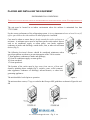
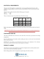
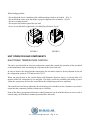
Beverage Air 3779 Champion Blvd Winston-Salem, NC 27105 INSTALLATION AND OPERATION MANUAL VM2, VM7, VM12, VM18 Congratulations! You have just purchased the finest commercial refrigeration available. •••• www.beverage-air.com •••• Table of Contents INSTALLATION AND OPERATION MANUAL ........................................................................ 1 APPLICATION ...................................................................................................................................... 3 PRODUCT REGISTRATION ................................................................................................................ 3 DIRECTIONS FOR STORAGE AND HANDLING THE EQUIPMENT ............................................ 3 STORAGE OF THE EQUIPMENT ................................................................................................... 3 UNCRATING ..................................................................................................................................... 3 MOVING THE EQUIPMENT ........................................................................................................... 3 PLACING AND INSTALLING THE EQUIPMENT ............................................................................ 4 ELECTRICAL REQUIREMENTS ........................................................................................................ 5 POSITIONING SHELVES ..................................................................................................................... 5 PRODUCT LOADING ........................................................................................................................... 5 UNIT OPERATION AND COMPONENTS.......................................................................................... 6 ELECTRONIC TEMPERATURE CONTROL: ................................................................................. 6 PRESCRIPTIONS, PROHIBITIONS AND OTHER USES FOR THE EQUIPMENT ........................ 8 SHELF SPECIFICATIONS.................................................................................................................... 8 MAINTENANCE GUIDELINES .......................................................................................................... 9 You have selected one of the finest commercial refrigeration units made. It is manufactured under strict quality controls with only the best quality materials available. Your Beverage Air cooler, when installed correctly and properly maintained will give you many years of trouble-free operation. WARNING! USE THIS APPLIANCE FOR ITS INTENDED PURPOSE AS DESCRIBED IN THIS MANUAL When using electrical appliances, basic safety precautions should be followed, including the following: Use this appliance for its intended purpose as described in this Owner Manual. This refrigerator must be properly installed and located in accordance with the Installation Instructions. We strongly recommend that any servicing be performed by a qualified individual. Do not allow children to climb, stand, or hang on the shelves in the refrigerator. They could damage the refrigerator and seriously injure themselves. Do not store or use gasoline or other flammable vapors and liquids in the vicinity of this or any other appliance. Unplug the refrigerator before cleaning and making repairs. •••• www.beverage-air.com • Pg. 2 •••• CAREFULLY READ THESE INSTRUCTIONS. This manual provides instructions in how to best locate, operate, and maintain this equipment. It is recommended to keep this manual for any future reference. APPLICATION The VM series of coolers have a sanitation listing permitting the merchandising of packaged food and beverage product. The unit must be located in an indoor environment where the ambient must be maintained less than 75oF/55%RH. PRODUCT REGISTRATION Write down the Serial number of your new unit for future reference. The Serial Number is found on the data plate located on the back of the unit. MODEL: ________________________ SERIAL NUMBER: _______________ DIRECTIONS FOR STORAGE AND HANDLING THE EQUIPMENT STORAGE OF THE EQUIPMENT If the equipment will be kept in storage, it is suggested to keep it in its original packing. In case you need your equipment to be inactive for a long period of time after being used, verify that it has been unplugged. After cleaning it thoroughly with a damp cloth, lukewarm water and neutral soap and carefully drying it, cover it with a polyethylene film or similar waterproof material. UNCRATING The following procedure is recommended for uncrating the unit: Remove the outer package by carefully cutting the shrink wrap and removing the 4 corner posts and top lid. Inspect for concealed damage. Immediately file a claim with the freight carrier if there is damage. Move your unit as close to the final location as possible before removing the wooden skid. MOVING THE EQUIPMENT The unit is constructed to facilitate using a forklift to handle it. (Fig. 1) Use this handling means to move the equipment as close as possible to the location where it will be installed. IMPORTANT: Never push, pull or strike the front or side glass. Figure 1 •••• www.beverage-air.com • Pg. 3 •••• PLACING AND INSTALLING THE EQUIPMENT ENVIRONMENTAL CONDITIONS THIS UNIT CANNOT BE INSTALLED IN ENVIRONMENTS WITH EXPLOSIVE GASES. THE EQUIPMENT IS DESIGNED ONLY FOR INDOOR OPERATION . The unit must be located in an indoor environment where the ambient is maintained less than 75oF/55%RH. For the correct performance of the refrigerating system, it is very important to leave at least 10 cm (4") of free space both at the sides and back to allow proper air circulation. Care must be taken to ensure that air drafts around the cooler are kept to a minimum. A minimum space must be kept between the cooler and air sources such as air conditioner supply or return grilles, vent hoods, appliance condenser air intake and discharge, outside doors, fans, or other air movement devices (Fig.2). The following horizontal distance should be considered minimums unless special precautions are taken to prevent interruption of the VM air curtain: 5’ from appliance condenser air intake and discharge, 10’ from air conditioner supply or return grilles, 10’ from vent hood, 15’ from open doors Figure Figure22 The location of the cooler must be kept away from sources of heat and humidity including direct sunlight (Fig.3), toasters, ovens, coffee warmers, other appliances condenser air discharge, infrared heaters, or other heat generating appliances. The unit should be leveled prior to operation. Figure 3 The unit must have casters, 6” legs, or sealed to the floor per NSF guidelines as shown in Figure 4A and 4B. •••• www.beverage-air.com • Pg. 4 •••• ELECTRICAL REQUIREMENTS The power cord of this appliance is equipped with a 3-prong (grounding) plug which mates with a standard 3-prong (grounding) wall outlet to minimize the possibility of electric shock hazard from this appliance. VM units require a dedicated outlet with the following type of receptacle: VM 2/7 5-15R VM 12/18 - 5-20R The use of extension cords is not permitted and will void the warranty. Model VM2 VM7 VM12 VM18 Voltage (V) Current (A) Circuit Required (A) 120 120 120 120 4 15 8 15 11 20 16 20 Before connecting your equipment, check that the electrical data on the data plate match your electrical output. IMPORTANT NOTICE: PLUG THE EQUIPMENT INDEPENDENTLY TO A LOAD CENTER WITH AN APPROPRIATE CIRCUIT BREAKER ACCORDING TO THE NAMEPLATE AMPS . POSITIONING SHELVES The shelves and holders have been fixed to the inside floor of the unit to prevent their loss during transportation. Insert the shelf brackets in the pilaster notches making sure they are at the same level such that the shelves remain horizontal. IMPORTANT: The products on each shelf must leave three to five centimeters of free clearance between them and the next shelf in order to allow proper air circulation. PRODUCT LOADING The VM series of units are not intended to be a pull down refrigerator and as such the product must be loaded at their intended merchandising temperature. Before loading products, allow the equipment to operate empty for at least two hours. •••• www.beverage-air.com • Pg. 5 •••• When loading products: - Do not block the lower ventilation grille with the packages about to be loaded. (Fig. 5) - Do not block the return vents that ensure a proper refrigerated air circulation. (Fig. 6) - Do not over hang the shelf. - Do not press the product against the rear wall - Never exceed the shelf weight limits. (See Shelf Specifications Pg.10) FIGURE 5 FIGURE 6 UNIT OPERATION AND COMPONENTS ELECTRONIC TEMPERATURE CONTROL: The unit is provided with an electronic temperature control that controls the operation of the unit based on the temperature of the air entering the evaporator at the front of the unit. In order to achieve the desired product temperature, the electronic control is factory adjusted to turn off the refrigeration system at 35ºF and start it at 39.5ºF. When you plug the unit in, the control display will illuminate. However, there is a start-up delay of 2 minutes before the compressor(s) are energized. This delay avoids the possibility that during a power failure the compressors are forced to restart before the refrigerant pressures are equalized. The control has been factory-adjusted with a defrosting cycle scheduled to last 6 minutes every hour to ensure that the evaporator performs without any ice build-up. None of the factory-programmed electronic control parameters can be modified unless an access code is entered (only your distributor's technical personnel have that code). •••• www.beverage-air.com • Pg. 6 •••• COMPRESSORS: The VM2, and VM7 has a single hermetic compressor. The VM12 and VM18 each have two hermetic compressors that start in two steps with a delay of 10 seconds to reduce the in-rush of current to the unit. CONDENSERS: The VM 7, 12, and 18 units incorporate a "maintenance free" condenser design in the refrigeration system which reduces the need for the regular cleaning process that fin and tube condensers require. Besides the savings in preventive maintenance costs, energy expenses will be stable throughout long periods of time since the condensers will remain "clean and unobstructed". The VM2 condenser requires frequent cleaning similar to most commercial refrigerators. EVAPORATOR: In the event it is believed that the unit has had a “freeze up” condition due to operation of the unit in high temperature or humidity conditions the evaporator can be inspected by removing the floor of the inside of the unit. In the event the evaporator is frozen, it can be thawed by emptying the cabinet of product and removing power until the coil is clear. CONDENSATION EVAPORATOR TRAY: When the equipment operates, condensed water from the environment is collected on the evaporator. During each off-cycle, the water drains to the evaporator tray located at the bottom of the unit where it is evaporated using the heat from the refrigeration system. SLIDING CONDENSING UNIT: The condensing unit can be pulled out, sliding it approximately 40 cm (16") to allow servicing the condenser motor(s), compressor(s) and electrical components. In order to service the condensing unit, remove the two screws that hold the lower front grill (one at each side). Remove the screws that hold the front bracket that clasps the condensing unit and slide it gently out to have access to the components you want to check. Once completed, every component must be returned to its original location for proper operation. LIGHTING: The lamp can be turned off with the switch located at the left side of the upper section, near the lamp. NIGHT CURTAIN: The night curtain should be pulled closed whenever the unit is not required for the active merchandising of product. •••• www.beverage-air.com • Pg. 7 •••• PRESCRIPTIONS, EQUIPMENT PROHIBITIONS AND OTHER USES FOR THE The equipment has been exclusively designed to maintain the proper temperature of packaged fresh food and beverages. Because the unit is not designed to cool the product down quickly, the product must be loaded at its appropriate temperature. Displaying pharmaceutical products in this unit is prohibited. (Fig.8) CAUTION - Do not remove grilles or panels that require using tools to be accessed - Do not keep the unit running unloaded. UNPLUG IT when you are not planning to use it. Figure 8 Using any electrical or electronic equipment entails the compliance with some fundamental rules. - Do not touch the unit with wet hands or feet. - Do not install the equipment outdoors. - Do not remove or ignore safety devices. - Do not leave objects on top of the unit. - Do not climb on top of the unit. - Never use direct or indirect water jets on the unit (Fig. 9). - Do not allow the electronic control to be adjusted by customers or unqualified personnel. For any adjustment you must contact your distributor. - Verify that the hot air stream from the condenser towards the back of the unit is not directed to other refrigeration units, which would compromise their operation. Figure 9 - Under no circumstance should you block the front grille of the unit. THE MANUFACTURER DOES NOT ASSUME ANY RESPONSIBILITY ARISING FROM DAMAGES CAUSED BY IMPROPER, INCORRECT, OR ERRONEOUS USE. It is important to instruct the user on the operation of the equipment according to this instruction manual, and to make sure that said manual is within reach of any operator that might use the unit. SHELF SPECIFICATIONS The shelves have been designed to withstand the rigors of normal use and loading with the following not to exceed evenly distributed weight per shelf: VM2: 20 kg (44 Lbs) VM7, VM12: 50 kg (110 Lbs). VM18: 60 kg (132 Lbs) This load limits must not be exceeded to prevent potential damage to the shelf and/or injury to users. •••• www.beverage-air.com • Pg. 8 •••• MAINTENANCE GUIDELINES Regularly and carefully cleaning the equipment prevents deterioration and product alteration. CLEANING THE UNIT Clean every week with only a damp piece of cloth and neutral soap each external and internal surface, and dry them with a clean soft cloth (Fig. 10). FIGURE 10 Never use flammable or abrasive products. The unit must never be cleaned with water jets. IMPORTANT: During maintenance and cleaning operations, make sure that good visibility conditions exist in the working area, using other light sources in case it is needed. Be very careful when working with moving and/or high-temperature parts. CLEANING THE CONDENSER COIL IMPORTANT WARRANTY INFORMATION: Condensers accumulate dirt and require regular cleaning. Dirty condensers result in compressor failure, product loss, and lost sales; which are not covered by warranty If you keep the condenser(s) clean you will minimize your service expense and lower your electrical costs. The following is a step-by-step guideline for the cleaning of the condenser(s): 1. 2. 3. 4. 5. Disconnect power to the unit. Take off front lower grill assembly by removing the two (2) screws in the top corners. Clean off accumulated dirt from the condenser coil(s) using a vacuum and/or a damp rag. Replace the grill assembly. Connect power to the unit and verify that when required the condensing unit(s) are running. If you cannot remove the dirt adequately, please call your refrigeration service company. •••• www.beverage-air.com • Pg. 9 •••• TECHNICAL ASSISTANCE If technical personnel assistance is required, you must immediately contact your distributor, specifying the kind of problem and clearly indicating the equipment model and serial number. If replacing parts is required, do it through your distributor. WARNING: Always ask for original spare parts AUTHORIZED DISTRIBUTOR: _____________________________________ COMMERCIAL NAME: _____________________________________ ADDRESS: _____________________________________ TELEPHONE: _____________________________________ E-MAIL: _____________________________________ •••• www.beverage-air.com • Pg. 10 ••••