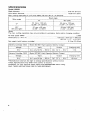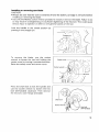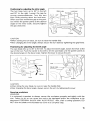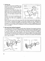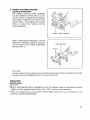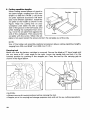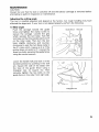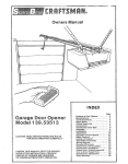
1
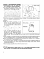
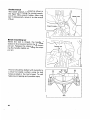
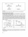
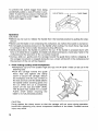
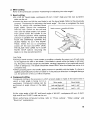
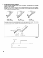
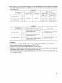
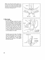
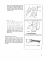
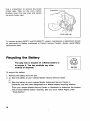
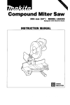
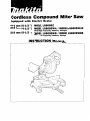
Cordless Compound Miter Saw
Equipped with Electric Brake
216 mm (8-1/2”) MODEL LSSOODZ
216 mm (8-112”) MODEL LSSOODWA / MODEL LSSOODWAE
With High Capacity Battery Charger
216 mm (S-ll2”)
MODEL LSSOODWB / MODEL LSSOODWBE
With High Capacity Battery Charger
INSTRUCTION MANUAL
SPECIFICATIONS
M o d e l LS800D
Blade diameter
.......................................................................................
2 1 6 m m (8-112")
..............................................................................
1 5 . 8 8 m m (5/8")
Hole (arbor) diameter
Max. c u t t i n g capacities (H x W ) w i t h blade 216 mm (8-1/2") in diameter
I
.,
Miter anole
I
Bevel angle
00
45O (left)
00
61 mm x 122 mm
( 2 - 3 / 8 " x 4 - 1 3/16")
4 5 m m x 1 2 2 mm
(1-3/4" x 4-13/16")
450
(left and right)
6 1 mm x 8 5 m m
(2-318'' x 3 - 3 / 8 " )
4 5 mm x 8 5 mm
( 1- 3 / 4 " x 3-3/8")
~
Battery Cartridge 1 8 2 2
Model DC1801 High Capacity Battery Charger
Voltage
Input
output
Charging time
18 V
A.C. only 5 0 Hz - 60 Hz
D.C. 7.2 V - 18 V
1 Hr.
I Battery Cartridge 1 8 3 3 1 Model DC1801 High Capacity Battery Charger
I
Voltage
I
Input
I
Output
~
18 V
2
~~
A.C. only 5 0 HZ - 60
HZ
~
~~
D.C. 7 . 2 V - 18 V
I
1
Charaina time
~~~
65 min.
I
For Your Own Safety Read Instruction Manual
Before Operating Compound Miter Saw
Save it for future reference
GENERAL SAFETY PRECAUTIONS
(For All Tools)
1. KNOW YOUR POWER TOOL. Read the owner's manual carefully. Learn the
tool's applications and limitations, as well as the specific potential hazards
peculiar t o it.
2.KEEP GUARDS IN PLACE and in working order.
3.REMOVE ADJUSTING KEYS AND WRENCHES. Form habit of checking t o
see that keys and adjusting wrenches are removed from tool before turning
it on.
4.KEEP WORK AREA CLEAN. Cluttered areas and benches invite accidents.
5.DON'T USE IN DANGEROUS ENVIRONMENT. Don't use power tools in damp
or wet locations, or expose them t o rain. Keep work area well lighted.
Don't use tool in presence of flammable liquids or gases.
6 . KEEP CHILDREN AWAY. All visitors should be kept safe distance from work
area.
7 . MAKE WORKSHOP CHILD PROOF w i t h padlocks, master switches, or by
removing starter keys.
8 . DON'T FORCE TOOL. It will do the job better and safer at the rate for which
it was designed.
9. USE RIGHT TOOL. Don't force tool or attachment t o do a job for which it
was not designed; for example, don't use circular saw for cutting tree limbs
or logs.
IO. WEAR PROPER APPAREL. Do not wear loose clothing, gloves, neckties, rings,
bracelets, or other jewelry which may get caught in moving parts. Nonslip
footwear is recommended. Wear protective hair covering t o contain long hair.
1 1 . ALWAYS USE SAFETY GLASSES. Also use face or dust mask if cutting
operation is dusty. Everyday eyeglasses only have impact resistant lenses,
they are NOT safety glasses.
12.SECURE WORK. Use clamps or a vise t o hold work when practical. It's safer
than using your hand and it frees both hands t o operate tool.
13.DON'T OVERREACH. Keep proper footing and balance at all times.
14.MAINTAIN TOOLS WITH CARE. Keep tools sharp and clean for best and
safest performance. Follow instructions for lubricating and changing accessories.
15.DISCONNECT BATTERY FROM TOOL before servicing; when changing
accessories such as blades, bits, cutters, and the like.
3
OF UNINTENTIONAL STARTING. Make sure s w i t c h is
in off position before inserting battery.
16. REDUCE THE RISK
17. USE RECOMMENDED ACCESSORIES. Consult the owner's manual for
recommended accessories. The use of improper accessories may cause risk
of injury t o persons.
18. NEVER STAND ON TOOL. Serious injury could occur i f the tool is tipped or
i f the cutting tool is accidentally contacted.
19. CHECK DAMAGED PARTS. Before further use of the tool, a guard or other
part that is damaged should be carefully checked t o determine that it will
operate properly and perform its intended function - check for alignment
of moving parts, binding of moving parts, breakage of parts, mounting, and
any other conditions that may affect its operation. A guard or other part that
is damaged should be properly repaired or replaced.
20. DIRECTION OF FEED. Feed work into a blade or cutter against the direction
of rotation of the blade or cutter only.
21. NEVER LEAVE TOOL RUNNING UNATTENDED. TURN POWER OFF. Don't
leave tool until it comes t o a complete stop.
4
ADDITIONAL SAFETY RULES
1. Wear eye protection.
2. Do not operate saw without guards in place.
3.Don’t use the tool in the presence of flammable liquids or gases.
4.Check the blade carefully for cracks or damage before operation.
Replace cracked or damaged blade immediately.
5. Use only flanges specified for this tool.
6.Be careful not to damage the arbor, flanges (especially the installing surface)
or bolt. Damage to these parts could result in blade breakage.
7. Make sure that the turn base is properly secured so it will not move during
operation.
8. For your safety, remove the chips, small pieces, etc. from the table top before
operation.
9. Avoid cutting nails. Inspect for and remove all nails from the workpiece before
operation.
IO. Make sure the shaft lock is released before the switch is turned on.
11. Be sure that the blade does not contact the turn base in the lowest position.
12. Hold the handle firmly. Be aware that the saw moves up or down slightly during
start-up and stopping.
13.Do not perform any operation freehand. The workpiece must be secured firmly
against the turn base and guide fence with the vise during all operations. Never
use your hand to secure the workpiece.
14.Keep hands out of path of saw blade. Avoid contact with any coasting blade.
It can still cause severe injury.
15.Never reach around saw blade.
16. Make sure the blade is not contacting the workpiece before the switch is turned
on.
17. Before using the tool on an actual workpiece, let it run for a while. Watch for
vibration or wobbling that could indicate poor installation or a poorly balanced
blade.
18. Wait until the blade attains full speed before cutting.
19. Stop operation immediately if you notice anything abnormal.
20. Do not attempt to lock the trigger in the on position.
21.Shut off power and wait for saw blade t o stop before servicing or adjusting tool.
22. Be alert at all times, especially during repetitive, monotonous operations. Don’t
be lulled into a false sense of security. Blades are extremely unforgiving.
23. Always use accessories recommended in this manual. Use of improper
accessories such as abrasive wheels may cause an injury.
24.Turn off tool and wait for saw blade to stop before moving workpiece or changing settings.
25. Remove battery from tool before changing blade or servicing.
SAVE THESE INSTRUCTIONS.
5
IMPORTANT SAFETY INSTRUCTIONS
FOR CHARGER &
BATTERY CARTRIDGE
1. SAVE THESE INSTRUCTIONS - This manual
contains important safety and operating instructions for battery charger.
2. Before using battery charger, read all instructions and cautionary markings
on (11 battery charger, (21 battery, and (3) product using battery.
3. CAUTION - To reduce risk of injury, charge only MAKITA Battery Cartridge
7000, 7001, 7002, 7033, 7100, 7120, 9000, 9001, 9002, 9033, 9100,
9101,9102,9120,9122,9133,1200,1201,1202,1210,1211,1222,1233,
1422,1433,1822,1833,9101A. 9102A. 1201A or 1202A. Other types of
batteries may burst causing personal injury and damage.
4. Do not expose charger t o rain or snow.
5. Use of an attachment not recommended or sold by the battery charger
manufacturer may result in a risk of fire, electric shock, or injury t o persons.
6. To reduce risk of damage t o electric plug and cord, pull by plug rather than
cord when disconnecting charger.
7. Make sure cord is located so that it will n o t be stepped on, tripped over, or
otherwise subjected t o damage or stress.
8. A n extension cord should n o t be used unless absolutely necessary. Use of
improper extension cord could result in a risk of fire and electric shock. If
extension cord m u s t be used, make sure:
a. That pins o n plug of extension cord are the same number, size, and shape
as those of plug on charger;
b. That extension cord is properly wired and in good electrical condition; and
c. That wire size is at least as large as the one specified in the table below.
TABLE 1
RECOMMENDED MINIMUM AWG SIZE FOR
EXTENSION CORDS FOR BATTERY CHARGERS
I Length of Cord (Feet) I
25
I
50
I AWG S i z e o f Cord
18
I
18
1
I 100 I 1 5 0 I
I
18
I
16
I
9. Do n o t operate charger w i t h damaged cord or plug - replace t h e m immediately.
I O . Do not operate charger if it has received a sharp blow, been dropped, or otherwise damaged in any way; take it t o a qualified serviceman.
11. Do not disassemble charger or battery cartridge; take it t o a qualified
serviceman when service or repair is required. Incorrect reassembly may
result in a risk of electric shock or fire.
12. To reduce risk of electric shock, unplug charger from outlet before attempting any maintenance or cleaning. Turning off controls will not reduce this risk.
6
ADDITIONAL SAFETY RULES
FOR CHARGER & BATTERY CARTRIDGE
1. Do not charge Battery Cartridge when temperature is BELOW 10°C (5OoF1
or ABOVE
4OoC (104OF).
2. Do not attempt t o use a step-up transformer, an engine generator or DC power
receptacle.
3.Do not allow anything t o cover or clog the charger vents.
4. Always cover the battery terminals w i t h the battery cover when the battery
cartridge is not used.
5. A battery short can cause a large current flow, overheating, possible burns
and even a breakdown.
(11 Do not touch the terminals w i t h any conductive material.
(2)Avoid storing battery cartridge in a container w i t h other metal objects such
as nails, coins, etc.
(3)Do not expose battery cartridge t o water or rain.
6. Do not store the tool and Battery Cartridge in locations where the temperature may reach or exceed 5OoC (122OF).
7. Do not incinerate the Battery Cartridge even i f it is severely damaged or is
completely worn out. The battery cartridge can explode i n a fire.
SAVE THESE INSTRUCTIONS.
7
Installing or removing battery cartridge
*Always switch off the tool before insertion or removal of the battery cartridge.
*To remove the battery cartridge, withdraw it from the tool while pressing the
buttons on both sides of the cartridge.
*To insert the battery cartridge, align the
tongue on the battery cartridge with the
groove in the housing and slip it into
place. Always insert it all the way until it
locks in place with a little click. If not, it
may accidentally fall out of the tool, causing injury to you or someone around you.
Do not use force when inserting the battery cartridge. If the cartridge does not slide in
easily, it is not being inserted correctly.
Charging
*Your new battery cartridge is not
charged. You will need to charge it before use. Use the high capacity battery
charger Model DC1801 to charge the battery cartridge.
Plug the high capacity battery charger
into the proper A.C. voltage source. The
charging light will flash in green color.
*Insert the battery cartridge so that the
plus and minus terminals on the battery
cartridge are on the same sides as their
respective markings on the high capacity
battery charger. Insert the cartridge fully into the port so that it rests on the charger port
floor.
When the battery cartridge is inserted, the charging light color will change from green to
red and charging will begin. The charging light will remain lit steadily during charging.
When the charging light color changes from red to green, the charging cycle is complete.
The charging time is approximately one hour.
If you leave the battery cartridge in the charger after the charging cycle is complete, the
charger will switch into its "trickle charge (maintenance charge)" mode which will last
approximately 24 hours.
*After charging, unplug the charger from the power source.
CAUTION:
The high capacity battery charger Model DCI 801 is for charging Makita battery cartridge.
Never use it for other purposes or for other manufacturer's batteries.
8
When you charge a new battery cartridge or a battery cartridge which has not been used
for a long period of time, it may not accept a full charge. This is a normal condition and
does not indicate a problem. You can recharge the battery cartridge fully after discharging
it completely and recharging a couple of times.
If you charge a battery cartridge from a just-operated tool or a battery cartridge which has
been left in a location exposed to direct sunlight or heat for a long time, the charging light
may flash in red color. If this occurs, wait for a while. Charging will begin after the battery
cartridge cools. The battery cartridge will cool faster if you remove the battery cartridge
from the high capacity battery charger.
If the charging light flashes alternately in green and red color, a problem exists and charging is not possible. The terminals on the charger or battery cartridge are clogged with
dust or the battery cartridge is worn out or damaged.
Trickle charge (Maintenance charge)
If you leave the battery cartridge in the charger to prevent spontaneous discharging after
full charge, the charger will switch into its ”trickle charge (maintenancecharge)” mode and
keep the battery cartridge fresh and fully charged.
Tips for maintaining maximum battery life
1. Charge the battery cartridge before completely discharged.
Always stop tool operation and charge the battery cartridge when you notice less tool
power.
2. Never recharge a fully charged battery cartridge.
Overcharging shortens the battery service life.
3. Charge the battery cartridge with room temperature at 10°C - 40°C (50°F - 104°F)
Let a hot battery cartridge cool down before charging it.
Installing auxiliary plate
Install the auxiliary plate using the notch in the tool‘s base and secure it by tightening the
hex. bolt.
Base
Auxiliary plate
-zFTD
Hex bolt
Auxiliary plate
Hex bolt
Base
Nut
9
Socket wrench
The socket wrench is stored as shown in
the figure. When using the socket wrench,
pull it out of the wrench holder. After using
the socket wrench, return it to the wrench
holder.
I
Bench mounting saw
When the tool is shipped, the handle is
locked in the lowered position by the stopper pin. Release the stopper pin by lowering the handle slightly and pulling the stopper pin.
I
I
This tool should be bolted with two bolts to
a level and stable surface using the bolt
holes provided in the tool’s base. This will
help prevent tipping and possible injury.
Bolt
10
Installing or removing saw blade
CAUTION:
*Always be sure that the tool is switched off and the battery cartridge is removed before
installing or removing the blade.
*Use only the Makita socket wrench provided to install or remove the blade. Failure to do
so may result in overtightening or insufficient tightening of the hex bolt. This could cause
serious injury to operator or others in the general vicinity of the tool.
Lock the handle in the raised position by
pushing in the stopper pin.
To remove the blade, use the socket
wrench to loosen the hex bolt holding the
center cover by turning it counterclockwise.
Raise the safety cover and center cover.
Press the shaft lock to lock the spindle and
use the socket wrench to loosen the hex
bolt (left-handed) clockwise. Then remove
t h e h e x bolt, outer flange and blade.
11
To install the blade, mount it carefully onto the spindle, making sure that the direction of
the arrow on the surface of the blade matches the direction of the arrow on the blade
case. Install the outer flange and hex bolt, and then use the socket wrench to tighten the
hex bolt (left-handed) securely counterclockwise while pressing the shaft lock.
-
Blade case
Return the safety cover and center cover to
its original position. Then tighten the hex
bolt clockwise to secure the center cover.
Release the handle from the raised position by pulling the stopper pin. Lower the
handle to make sure that the safety cover
moves properly.
Socket wrench
Safety cover
When lowering the handle, the safety
cover rises automatically. The cover returns
to its original position when the cut is completed and the handle is raised. NEVER
DEFEAT OR REMOVE THE SAFETY
COVER. In the interest of your personal
safety, always maintain the safety cover in
good condition. Any irregular operation of
the safety cover should be corrected i m m e
diately. NEVER USE THE TOOL WITH A
FAULTY SAFETY COVER. If the seethrough safety cover becomes dirty, or sawdust adheres to it in such a way that the blade
and/or workpiece is no longer easily visible, remove the battery cartridge and clean the
cover carefully with a damp cloth. Do not use solvents or any petroleum-based cleaners
on the plastic cover.
12
Dust bag
The use of the dust bag makes cutting
operations clean and dust collection easy.
To attach the dust bag, fit the bag's entry
port over the dust nozzle. When the dust
bag is about half full, remove the dust bag
from the tool and pull the fastener out.
Empty the dust bag of its contents, tapping
it lightly so as to remove particles adhering
to the insides which might hamper further
collection.
7
Dust nozzle
NOTE:
If you connect a Makita vacuum cleaner to your saw, more efficient and cleaner operations
can be performed.
Positioning kerf board
This tool is provided with the kerf boards in the turn base. The kerf boards are factory
adjusted so that the saw blade does not contact the kerf boards. Before use, adjust the
kerf boards as follows:
First, remove the battery cartridge. Loosen the all screws (2 each on left and right) securing the kerf boards. Re-tighten them to the extent that the kerf boards can be easily
moved by hand. Lower the handle fully and push in the stopper pin to lock the handle in
the lowered position. Pull the carriage
toward you fully. Adjust the kerf boards so
that the kerf boards just contact the sides
of blade teeth slightly. Tighten the front
screws (do not tighten firmly). Push the carriage toward the guide fence fully and
adjust the kerf boards so that the kerf
boards just contact the sides of blade teeth
slightly. Tighten the rear screws (do not
tighten firmly). After adjusting the kerf
boards, release the stopper pin and raise
the handle. Then tighten the all screws
securely.
13
Kerf board
Left bevel cut
Straight cut
CAUTION:
After changing the bevel angle, always readjust the kerf boards as described above.
Maintaining maximum cutting capacity
This tool is factory adjusted to provide the max. cutting capacity for a 216 mm (8-1/2")
saw blade. When using a saw blade other than 216 m m (8-1/2") saw blade, adjust the
lower limit position of the blade as follows:
First, remove the battery cartridge. Push the carriage toward the guide fence fully and
lower the handle completely. Use the socket wrench to turn the adjusting bolt until the
periphery of the blade extends slightly below the top surface of the turn base a t the point
where the front face of the guide fence meets the top surface of the turn base. With the
battery cartridge removed, rotate the blade by hand while holding the handle all the way
down to be sure that the blade does not contact any part of the lower base. Re-adjust
slightly, if necessary.
Turn base
Adjusting bolt
Periphery
of blade
I
I
Top surface
Guide fence
Guide fence
CAUTION:
After installing a new blade, always be sure that the blade does not contact any part of
the lower base when the handle is lowered completely. Always do this with the battery
cartridge removed.
14
Positioningfor adjusting the miter angle
The turn base turns up to 52" to the left
and 52" to the right. Loosen the grip by
turning counterclockwise. Turn the turn
base while pressing down the lock lever.
When you have moved the grip to the position where the pointer points to the desired
angle on the miter scale, securely tighten
the grip clockwise.
I
Miter scale
Lock lever
CAUTION:
*When turning the turn base, be sure to raise the handle fully
*After changing the miter angle, always secure the turn base by tightening the grip firmly.
Positioningfor adjusting the bevel angle
The saw blade tilts up to 45" to the left. To adjust the bevel angle, loosen the lever at the
rear of the tool. Push the handle to the left to tilt the saw blade until the pointer points to
the desired angle on the bevel scale. Tighten the lever to secure the arm.
Arm
Bevel scale
Lever
Pointer
CAUTION:
*When tilting the saw blade, be sure to raise the handle fully.
*After changing the bevel angle, always secure the arm by tightening the lever.
Securing workpiece
WARNING :
It is extremely important to always secure the workpiece properly and tightly with the
vise. Failure to do so can cause the tool to be damaged and/or the workpiece to be
destroyed. PERSONAL INJURY MAY ALSO RESULT. Also, after a cutting operation, DO
NOT raise the blade until the blade has come to a complete stop.
15
1. Vertical vise
The vertical vise can be installed in two
positions on either the left or right side
of the guide fence, or the holder assembly (optional accessory).
Insert the vise rod into the hole in the
guide fence or the holder assembly and
tighten the screw to secure the vise rod.
(Note: When using the holder assembly,
install it on the holder as shown in the
figure.)
Position the vise arm according to the
thickness and shape of the workpiece
Turn base
and secure the vise arm by tightening
the screw.
Make sure that no part of the tool contacts the vise when lowering the handle fully or
when pulling or pushing the carriage. If some part contacts the vise, reposition the
vise. Press the workpiece flat against the guide fence and the turn base. Position the
workpiece at the desired cutting position and secure it firmly by tightening the vise
knob. The maximum thickness of workpieces which can be secured by the vertical vise
is 61 mm (2-3/8").
2. Horizontal vise (optional accessory)
The horizontal vise can be installed on the left side of the base. By turning the vise knob
counterclockwise, the screw is released and the vise shaft can be moved rapidly in and
out. To grip workpieces, turn the vise knob gently clockwise until the projection reaches
its topmost position, then fasten securely. If the vise knob is forced in or pulled out
while being turned clockwise, the projection may stop a t an angle. In this case, turn the
vise knob back counterclockwise until the screw is released, before turning again gently
clockwise. The maximum width of workpieces which can be secured by the horizontal
vise is 120 mm (4-3/4").
I
Vise knob
Vise shaft
16
i r
Projection
3. Holders and holder assembly
(optional accessories)
The holders and the holder assembly
can be installed on either side as a convenient means of supporting workpieces
horizontally. Install them as shown in the
figures below. Then tighten the screws
firmly to secure the holders and the
holder assembly.
Hoider
When cutting long workpieces, use the
holder-rod assembly (optional accessory). It consists of two holder assemblies
and two rods 12.
Holder assembly
Holder assembly
I
CAUTION:
Always support long workpieces level with the top surface of the turn base for accurate
cuts and to prevent dangerous loss of control of the tool.
OPERATION
Switch action
CAUTION:
Before inserting the battery cartridge into the tool, always check to see that the switch
trigger actuates properly and returns to the “OFF” position when released.
*When not using the tool, remove the lock-off button and store it in a secure place. This
prevents unauthorized operation.
17
To prevent the switch trigger from being
accidentally pulled, a lock-off button is provided. To start the tool, press in the lock-off
button and pull the switch trigger. Release
the switch trigger to stop.
Lock-of f button
I
Operation
CAUTION:
*Before use, be sure to release the handle from the lowered position by pulling the stopper pin.
*Make sure the blade is not contacting the workpiece, etc. before the switch is turned on.
*Do not apply excessive pressure on the handle when cutting. Too much force may result
in overload of the motor and/or decreased cutting efficiency.
*Gently press down the handle to perform the cut. If the handle is pressed down with
force or if lateral force is applied, the blade will vibrate and leave a mark (saw mark) in the
workpiece and the precision of the cut will be impaired.
*During a slide cut, gently push the carriage toward the guide fence without stopping. If
the carriage movement is stopped during the cut, a mark will be left in the workpiece and
the precision of the cut will be impaired.
1. Press cutting (cutting small workpieces)
*Workpieces up to 61 mm (2-3/8") high and 122 mm (4-13/16") wide can be cut in the
following way.
*Push the carriage toward the guide
fence fully and tighten the clamp
screw to secure the carriage. Secure
the workpiece with the vise. Switch on
the tool and wait until the blade attains
full speed before lowering gently into
the cut. When the cut is completed,
switch off the tool and WAIT UNTIL
THE BLADE HAS COME TO A COMPLETE STOP before returning the
blade to its fully elevated position.
CAUTION:
Firmly tighten the clamp screw so that the carriage will not move during operation.
Insufficient tightening may cause unexpected kickback of the blade. Possible serious
injury may result.
18
2. Miter cutting
Refer to the previously covered "Positioning for adjusting the miter angle".
3. Bevel cutting
*At a left 45" bevel angle, workpieces 45 mm (1-3/4") high and 122 mm (4-13/16")
wide can be cut.
*Loosen the lever and tilt the saw blade to set the bevel angle. Refer to the previously
covered "Positioning for adjusting the bevel angle". Be sure to re-tighten the lever
firmly to secure the selected bevel
angle safely. Secure the workpiece
Apply pressure in parallel with blade
with the vise. Switch on the tool and
wait until the blade attains full speed.
Then gently lower the handle to the
fully lowered position while applying
pressure in parallel with the blade and
PUSH THE CARRIAGE TOWARD THE
GUIDE FENCE TO CUT THE WORKPIECE. When the cut is completed,
switch off the tool and WAIT UNTIL
THE BLADE HAS COME TO A COMPLETE STOP before returning the
blade to its fully elevated position.
CAUTION:
*During a bevel cutting, it may create a condition whereby the piece cut off will come
to rest against the side of the blade. If the blade is raised while the blade is still rotating, this piece may be caught by the blade, causing fragments to be scattered around
which is dangerous. The blade should be raised ONLY after the blade has come to a
complete stop.
*When pressing down the handle, apply pressure in parallel with the blade. If a force is
applied perpendicularlyto the turn base or if the pressure direction is changed during a
cut, the precision of the cut will be impaired.
4. Compound cutting
Compound cutting is the process in which a bevel angle is made at the same time in
which a miter angle is being cut on a
workpiece. Compound cutting can be
performed at angle shown in the table
right.
Left and Right 45"
Left 0 - 40"
At the miter angle of left 45" and bevel angle of left 45", workpieces 45 mm (1-3/4")
high and 85 mm (3-3/8")
wide can be cut.
When performing compound cutting, refer to "Press cutting", "Miter cutting" and
"Bevel cut" explanations.
19
5. Cutting crown and cover moldings
*Crown and cove moldings can be cut on a compound miter saw with the moldings
laid flat on the turn base.
*There are two common types of crown moldings and one type of cove moldings;
52/38" wall angle crown molding, 45" wall angle crown molding and 45" wall angle
cove molding. See illustrations below.
Ceiling
Ceiling
52/38' type
crown molding
45" type
crown molding
Ceiling
45" type
cove molding
*There are crown and cove molding joints which are made to fit "Inside" 90" corners
(0
and 0)
in Fig. C ) and "Outside" 90" corners (0
and @ in Fig. C).
- -
Inside corner
Outside corner
I
Fig. (C)
Inside corner
Outside corner
20
When cutting crown and cove moldings, set the bevel angle and miter angle as indicated
in the table (A)and position the moldings on the top surface of the saw base as indicated
in the table (B).
Table ( A I
Bevel angle
Molding position
in Fig. (C)
52/38''
type
45O type
Miter angle
52/38''
type
45' type
For inside corner
Left 33.9O
Left 30'
(3)
Right 31.6"
Molding
pos'tion
in Fig (C)
1
li,
l?i
For inside corner
Molding edge against guide fence
I
Ceilinq contact edqe should be
against guide fence.
I
Right 35.3'
Finished piece
Finished piece will be on the
Left side of blade.
Wall contact edge should be
against guide fence.
For outside corner
a
Ceiling contact edge should be
against guide fence.
Finished piece will be on the
Of blade'
Right side
(Example)
In the case of cutting 52/38' type crown molding for position 0 in Fig. (C):
*Tilt and secure bevel angle setting to 33.9O LEFT.
*Adjust and secure miter angle setting to 31.6O RIGHT.
*Lay crown molding with its broad back surface down on the turn base with its CEILING
CONTACT EDGE against the guide fence on the saw.
*The finished piece to be used will always be on the LEFT side of the blade after the
cut has been made.
21
Ceiling
Compound Miter Saw
Miter and Bevel Angle Settings
-
3
Wall to Crown Molding Angle: 52 I 3 8 degrees
I
i%1 1 I
Wall
42.8
66
I
42.2
41.9
41.7
41.4
G7
I
A1 1
I
40.8
I
45.1
44.6
44.0
43.5
1
A7 q
I
42.4
I
-+z-p+\
68
39.9
1
I
103
1041
29.4
29.0
109
28.0
27.6
27.2
37.8
37.4
37.1
36.8
36.5
87
88
I*
I
35.5
35.2
34.9
34.5
I
I
Miter
1
26.1
25.7
24.5
24.1
23.7
37.2
36.8
36.3
35.8
35.3
I
I
I
34.4
33.9
33.4
33.0
32.5
I
1-1
122
123
124
125
126
127
130
23.9
20.3
22.8
22.5
22.1
21.7
21.3
21.0
20.6
18.8
18.5
18.1
17.8
17.4
17.1
19.5
16.0
18.7
I
1431
1441
1451
146
147
14.5
14.1
3.7
13.3
12.9
1481
12.5
153
154
155
11.0
10.8
10.2
9.8
1-
I
I
I
11.6
11.3
11.0
10.7
10.3
10.0
1
8.4
7.8
6.8
7.5
4.9
167
1 1 I
170
169
171
3.7
4
:
X
:
3.5
2.8
I
174
94
32.5
29.9
zz 1 1 :;:;I11 -
97
100
22
I
I
I
40.8
185
86
Bevel
I
31.5
31.1
30.8
30.4
I
14.0
28.6
27.3
139
1401
16.0
15.6
I
13.0
12.8
1 l a
1801
0.0
I
0.0
I
Ceiling
Compound Miter Saw
Miter and Bevel Angle Settings
-
2
Wall to Crown Molding Angle:
Wall
I
Bevel
I
Miter
45 degrees
I
I
Angle
(deg.)
Angle
(deg.)
Angle
(deg.)
26.1
29.4
25.2
24.9
24.6
24.2
28.1
27.6
27.2
26.8
112
23.6
233
25.5
115
22.3
24.3
1181
1191
120
121
122
123
124
1251
21.4
21.0
20.7
20.4
20.0
19.7
19.4
19.1
23.4
23.0
122.6
22.2
21.8
21.4
21.0
20.6
1 20.2
37.3
64
65
66
36.8
36.6
36.4
49 1
48.5
48.0
47.4
108
109
I
147
1481
1491
D 150
151
152
153
154
lt-Ep+p
d
81
82
83
84
85
86
87
88
1-
1-
94
32.5
32.3
32.0
31.7
31.4
31.1
30.9
30.6
39.6
39.1
38.6
38.1
37.7
37.2
36.7
36.2
29.4
34.3
28.8
28.5
33.4
32.9
32.0
I
I
27.0
30.7
I
1
t7zpq-T
18.4
I
1281
129
1301
I
135
18.1
17.7
17.4
19.4
I
I
1
16.0
15.7
19.0
18.6
18.2
16.7
16.3
ppq-is-
1 :l:/ ::::1
140
100
I
1
1
15.0
15.6
14.0
15.2
14.8
14.4
I
I
I
11.8
11.5
11.1
10.7
10.4
10.0
9.6
9.3
157
158
159 I
160
161
162
163
1641
1651
166 I
4.9
I
5.0
1671
4 6
I
4 6
172
2 8
1731
2:
174
175
1761
177
1781
1
1.8
1.4
1.1
0.7
8.1
7.8
7.4
7.1
6.7
I
I
6.4
6.0
5.6
5.3
170
171
,
I
11.6
11.2
0.9
10.5
10.2
9.8
9.5
9.2
1
I
1
I
I
8.2
7.8
7.5
7.1
6.7
6.4
6.0
5.7
5.3
2.8
2 5
1.8
1.4
1.1
0.7
1 180
23
6. Cutting repetitive lengths
When cutting several pieces of stock to
the same length, ranging from 220 mm
(8-5/8") to 365 mm (14-3/8"), use of the
set plate (optional accessory) will facilitate more efficient operation. Install the
set plate on the holder as shown in the
figure. Align the cutting line on your
workpiece with either the left or right
side of the groove in the kerf board, and
while holding the workpiece from moving, move the set plate flush against the
end of the workpiece. Then secure the
set plate with the screw. When the set
plate is not used, loosen the screw and turn the set plate out of the way.
NOTE:
Use of the holder-rod assembly (optional accessory) allows cutting repetitive lengths,
ranging from 220 mm (8-518")to 2,230 mm (7.3 ft.)
Carrying tool
Make sure that the battery cartridge is removed. Secure the blade at 0" bevel angle and
the turn base at 52" miter angle to the right. Lower the handle fully and lock it in the
lowered position by pushing in the stopper pin. Carry the tool by the carrying grip as
shown in the figure below.
CAUTION:
*Always secure all moving portions before carrying the tool.
*Stopper pin is for carrying and storage purposes only and not for any cutting operations.
24
MAINTENANCE
CAUTION:
Always be sure that the tool is switched off and the battery cartridge is removed before
attempting to perform inspection or maintenance.
Adjusting the cutting angle
This tool is carefully adjusted and aligned a t the factory, but rough handling may have
affected the alignment. If your tool is not aligned properly, perform the following:
1) Miter angle
Push the carriage toward the guide
fence and tighten the clamp screw to
secure the carriage. Loosen the grip
which secures the turn base. Turn the
turn base so that the pointer points to 0"
on the miter scale. Then turn the turn
base slightly clockwise and counterclockwise to seat the turn base cozily in
the 0" miter notch. (Leave as it is if the
pointer does not point to O".) Loosen the
three hex bolts securing the guide fence
using the socket wrench.
Guide fence
Hex bolt
Lower the handle fully and lock it in the
lowered position by pushing in the lock
pin. Square the side of the blade with
the face of the guide fence using a
triangular rule, try square, etc. Then
securely tighten the hex bolts on the
guide fence in the order from right side.
I
Triangular rule
25
Make sure that the pointer points to 0"
on the miter scale. .If the pointer does
not point to 0", loosen the screw which
secures the pointer and adjust the pointer so that it will point to 0".
I
I
Miter.scale
2) Bevel angle
i) 0" bevel angle
Push the carriage toward the guide
fence and tighten the clamp screw to
secure the carriage. Lower the handle
fully and lock it in the lowered position
by pushing in the lock pin. Loosen the
lever at the rear of the tool. Turn the
0" bevel angle adjusting bolt (lower
bolt) on the right side of the arm two
or three revolutions counterclockwise
to tilt the blade to the right.
Carefully square the side of the blade
with the top surface of the turn base
using the triangular rule, try square,
etc. by turning the 0" bevel angle
adjusting bolt clockwise. Then tighten
the lever securely.
I I
I
Pointer
0"bevel angle
adjusting bolt
Triangular rule
I
of turn base
26
Make sure that the pointer on the arm
points to 0" on the bevel scale on the
arm holder. If it does not point to 0",
loosen the screw which secures the
pointer and adjust the pointer so that it
will point to 0".
ii) 45" bevel angle
Adjust the 45" bevel angle only after
performing 0" bevel angle adjustment.
To adjust left 45" bevel angle, loosen
the lever and tilt the blade 45" to the
left. Make sure that the pointer on the
arm points to 45" on the bevel scale
on the arm holder. If the pointer does
not point to 45", turn the 45" bevel
angle adjusting bolt (upper bolt) on the
right side of the arm until the pointer
points to 45".
/
45" bevel angle adjusting bolt
Replacing carbon brushes
Remove and check the carbon brushes
regularly. Replace when they wear down
to the limit mark. Keep the carbon brushes
clean and free to slip in the holders. Both
carbon brushes should be replaced at
the same time. Use only identical carbon
brushes.
/
Limit mark
27
Use a screwdriver to remove the brush
holder caps. Take out the worn carbon
brushes, insert the new ones and secure
the brush holder caps.
Brush holder cap
To maintain product SAFETY and RELIABILITY, repairs, maintenance or adjustment should
be performed by Makita Authorized or Factory Service Centers, always using Makita
replacement parts.
Recycling the Battery
The only way to dispose of a Makita battery is
to recycle it. The law prohibits any other
method of disposal.
@
Ni-Cd
To recycle the battery:
1. Remove the battery from the tool.
2. a). Take the battery to your nearest Makita Factory Service Center
or
b). Take the battery to your nearest Makita Authorized Service Center or
Distributor that has been designated as a Makita battery recycling location.
Call your nearest Makita Service Center or Distributor to determine the location
that provides Makita battery recycling. See your local Yellow Pages under
'Tools-Electric'
28
ACCESSORIES
CAUTION:
These accessories or attachments are recommended for use with your Makita tool specified in this
manual. The use of any other accessories or attachments might present a risk of injury t o persons.
The accessories or attachments should be used only in the proper and intended manner.
-
Dust bag
Part No. 122523-9
Holder
Part No. 192673-4
Socket wrench 10
Triangular rule
Part No. 762001-3
Part No. 782223-9
Lock-off button
Part No. 41 1478-6
-
Carbide-tipped saw blade
Vertical vise
Part No. 122571-8
Safety goggles
Part No. 191686-2
Fast, smoother, longer sawing without
blade sharpening. Curs wood.
29
-
Set plate
Part No. 122551-4
Vise assembly (horizontal vise)
Part No. 122563-7
High Capacity Battery Charger
Model DC1801
Holder assembly
Part No. 192713-8
Ni-MH (Nickel Metal Hydride) battery 1833
Part No.192828-1
Battery cartridge 1822
Part No. 192826-5
30
-
Battery cover
Part No. 41 4938-7
Jan.-20-'2000
US
216 mm (8-1/2")
CORDLESS COMPOUND MITER SAW
Model LS800D
Note: The switch and other part configurations
may differ from country to country.
31
MACHINE
1
2
1
1
3
3
5
4
5
6
7
8
9
10
11
12
13
14
15
16
17
18
19
20
21
22
23
24
25
26
27
28
29
30
31
32
33
34
35
36
37
38
39
40
41
42
43
44
45
46
47
48
49
50
51
52
53
54
55
56
57
58
1
1
1
1
1
1
2
1
1
1
1
2
2
1
2
3
1
1
1
1
1
1
1
1
1
1
1
1
1
1
2
1
1
1
1
1
1
1
1
1
1
1
W
Handle Set [With Item 211
Switch Button
Pan Head Screw M5x45
Tapping Screw 4x18
Compression Spring 4
Lock Off Lever
P," 5
Battery Holder
Switch
Switch Lever
Tapping Screw 4x18
Rear Cover
Name Plate
Brush Holder
Brush Holder
Carbon Brush
Holder Cap
Motor Housing
Tapping Screw 4x60
Pan Head Screw M5x45
Handle Set IWith Item 11
Ball Bearing 627LL8
Yoke Unit
Baffle Plate
ARMATURE ASSEMBLY
IWifh Item 2 2 & 281
Shaft Lock
Compression Spring 5
Ball Bearing 6000LL8
Oust Nozzle
0 Ring 3 5
Makita Label
Sleeve 17 23
Torsion Spring 28
Sleeve 17 23
Hex Sockel Head Bolt M6x10
Tapping Screw Bind CT 4x8
Tapping Screw Bind CT 4x12
Wrench Holder
Blade Case IWith Item 311
Hex Socket Head Bolt M6x20
Flat Washer 6
Ring 6
Link Plate
Stop Ring E 5
Flat Washer 6
Pin 6
E
97
98
99
100
101
102
103
104
105
1
1
1
1
1
1
1
1
1
1
1
1
1
1
1
1
1
1
1
2
1
1
1
2
2
1
1
1
1
1
4
1
1
1
2
2
1
1
1
1
1
1
1
1
1
1
1
center Cover
t i e x B O I ~~ 6 ~ 1 4
Flat Head Screw M 5
Center Washer
Spiral Spring 26
Safety Cover
Flat Washer 5
Pan Head Screw M 5 x 2 0
Pan Head Screw M4x12
Lever 1 0 0
Hex N u t M 1 0 - 1 7
Compression Spring 5
Flat Washer 10
Flat Washer 10
Hex Lock Nut M 1 0 - 1 7
n e x Bolt ~ 6 x 1 6
Knob 2 0
0 Ring 5
stopper Pl"
Hex Bolt M6x16
Arm Complete
Screw M 1 0
P," 5
Hex Socket Head Bolt M10x35
Spring Washer 1 0
Indication Plate
Pan Head Screw M4x12
Sub Arm
Rod 1 6 - 1 0 0
Guide Fence
Hex Bolt M6x25
Screw M6x10
Kerf Board
Kerf Board
Tapping Screw Bind CT 4x12
Tapping Screw Bind CT 4x12
Hex Lock Nut M 8 - 1 3
Flat Washer 8
P," 5
Turn Base
Tapping Screw Bind CT 4x12
Indication Plate
Compression Spring 7
Lock Pin
Pin3
Lock Lever
Grip 32
Ball Bearing 607LLB
Heltcal Gear 60
Ring 12
Bearing Box
Ball Bearing 6201DDW
Spindle
106
to7
108
109
110
11 1
1
1
2
1
1
1
Support Plate
Lack Plate
Tapping Screw Bind CT 4x12
Slide Plate
Slide Plate
Base Complete
Bearing Retainer 5 8
112
113
114
115
116
2
5
2
1
1
Screw M6x10
Cap 20
Tapping Screw Bind CT 4x12
Miter Scale Plate
Hex Bolt Max55
1
1
1
1
1
1
1
2
1
1
1
Pan Head Screw M5x16
Inner Flange 45
Outer Flange 4 5
Hex Bolt M6x18
1
center Plate
59
60
61
62
63
64
65
66
67
68
69
70
71
72
73
74
75
76
77
78
79
80
81
82
83
84
85
86
87
88
89
90
91
92
93
94
95
96
Note The swhtch and other part SpeciIicatiOnS may differ from country t o country
32
MAKmA LIMITEDONE YEAR WARRANTY
Warranty Policy
Every Makita tool is thoroughly inspected and tested before leaving the factory. It is warranted to
be free of defects from workmanship and materials for the period of ONE YEAR from the date of
original purchase. Should any trouble develop during this one-year period, return the COMPLETE
tool, freight prepaid, to one of Makita’s Factory or Authorized Service Centers. If inspection shows
the trouble is caused by defective workmanship or material, Makita will repair (or at our option,
replace) without charge.
This Warranty does not apply where:
repairs have been made or attempted by others:
repairs are required because of normal wear and tear:
The tool has been abused, misused or improperly maintained;
alterations have been made to the tool.
IN NO EVENT SHALL MAKITA BE LIABLE FOR ANY INDIRECT, INCIDENTAL OR CONSEQUENTIAL DAMAGES FROM THE SALE OR USE OF THE PRODUCT. THIS DISCLAIMER
APPLIES BOTH DURING AND AFTER THE TERM OF THIS WARRANTY.
MAKITA DISCLAIMS LIABILITY FOR ANY IMPLIED WARRANTIES, INCLUDING IMPLIED
WARRANTIES OF “MERCHANTABILITY” AND “FITNESS FOR A SPECIFIC PURPOSE,”
AFTER THE ONE-YEAR TERM O F THIS WARRANTY.
This Warranty gives you specific legal rights, and you may also have other nghts which vary from
state to state. Some states do not allow the exclusion or limitation of incidental or consequential
damages, so the above limitation or exclusion may not apply to you. Some states do n i t allow
limitation on how long an implied warranty lasts, so the above limitation may not apply to you.
Makita Corporation of America
2650 Buford Hwy., Buford, GA 30518
884229-066
PRINTED IN JAPAN
2000 - 2 - N