1
MIRROR VT Terminal Emulation
For 8 Series Mobile Computers:
8000 / 8300 / 8400 / 8500
DOC Version 2.27
Copyright © 2006~2010 CIPHERLAB CO., LTD.
All rights reserved
The software contains proprietary information of CIPHERLAB CO., LTD.; it is provided
under a license agreement containing restrictions on use and disclosure and is also
protected by copyright law. Reverse engineering of the software is prohibited.
Due to continued product development this information may change without notice. The
information and intellectual property contained herein is confidential between CIPHERLAB
and the client and remains the exclusive property of CIPHERLAB CO., LTD. If you find
any problems in the documentation, please report them to us in writing. CIPHERLAB
does not warrant that this document is error-free.
No part of this publication may be reproduced, stored in a retrieval system, or
transmitted in any form or by any means, electronic, mechanical, photocopying,
recording or otherwise without the prior written permission of CIPHERLAB CO., LTD.
For product consultancy and technical support, please contact your local sales
representative. Also, you may visit our web site for more information.
The CipherLab logo is a registered trademark of CIPHERLAB CO., LTD.
All brand, product and service, and trademark names are the property of their registered
owners.
The editorial use of these names is for identification as well as to the benefit of the
owners, with no intention of infringement.
CIPHERLAB CO., LTD.
Website: http://www.cipherlab.com
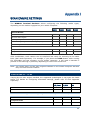
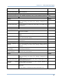
RELEASE NOTES
Version
Date
Notes
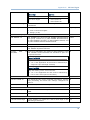
2.27
Dec. 02, 2010
New: System Requirements
Modified: Appendix I~II — support Coop 25 for CCD/Laser
(8000/8300/8400)
Modified: Appendix III — add Continuous/Test/Alternate/Auto Off
Mode and support Code 11 for Long Range Laser (8300 only)
Modified: Appendix I~IV — add more GS1 DataBar symbologies
Modified: Introduction — Special ESC Commands & Hardware
Test, add two ESC commands
Modified: Appendix II~IV — update default values
Modified: Appendix IV — Chinese 25, Matrix 25, Picklist Mode, 1D
Inverse, 2D Inverse, UPU FICS Postal and USPS 4CB/One Code/
Intelligent Mail
New: support 8400
New: “Alternatives to Download Settings” section
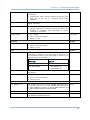
2.26
Jun. 14, 2010
2.25
Feb. 09, 2010
2.24
Feb. 08, 2010
2.23
2.22
Nov. 24, 2009
July 08, 2009
Modified: 3.5.3 Auto SignOn — Username and password limitation
Modified: Appendix I — support Code 11 for Long Range Laser
(8300 only)
Modified: Introduction
Insert/Replace
—
Getting
Started,
remove
icon for
Modified: Appendix V Function Key Mapping — removed
Modified: Appendix IV — Reader Settings Table
New: 2.1.4 Code ID
Modified: 2.3.1 Input — add Check Code Length
Modified: Chapter 3 Barcode screenshot updated
Modified: Appendix I — support ISBT 128 for CCD/Laser
Modified: Appendix II — support ISBT 128 for CCD/Laser
Modified: Appendix II — support UPC-E1 for CCD/Laser
New: Appendix II — Code ID Table
New: Appendix III — Code ID Table
New: Appendix IV — Code ID Table
New: support 8400-2D
Modified: 3.4.2 WEP Key — change to ASCII input
Modified: 3.4.3 WPA-PSK/WPA2-PSK Passphrase — change to
ASCII input
New: Features — support quick download by saving download
properties to an initial file
Modified: Special ESC Commands & Hardware Test — Buzzer Test
Modified: Utilities Menu — remove “RF”
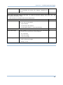
2.21
2.20
2.10
Mar. 03, 2009
Jan. 16, 2009
July 17, 2008
Modified: 1.6 Download & Baud Rate — remove “RF”
Modified: Getting Started – add hot keys F1, F2, F3 and F9
Oct. 02, 2007
June 12, 2006
Modified: remove Bluetooth-related descriptions (3560 phased
out)
New: “Special ESC Commands & Hardware Test” section
Modified: 2.3.2 Scanner – remove special ESC commands
Modified: 2.5 Hardware Test – remove
Modified: 4.1 Emulation Type – remove vt102, ANSI
Modified: 4.4.3 Horizontal Steps — FN key combination on 8000
Modified: 4.4.5 Cursor Tracking — FN key combination on 8000
Modified: 4.5.2 Keypad Type – add 8300 Keypad Type
Modified: Appendixes I~III — GS1-128 (EAN-128), GS1 DataBar
Omnidirectional (RSS-14), GS1 DataBar Limited (RSS Limited),
GS1 DataBar Expanded (RSS Expanded)
Modified: System tab (1) remove Func Toggle to the Emulation
tab (2) add Macro Frame
Modified: Barcode tab (1) add LED Flashing to Advanced Settings
Modified: Emulation tab (1) add 8500 Keypad Type (2) support
8500 44-TE Key
New: GPRS tab for 8500 only
Modified: Wireless LAN tab (1) change WPA Passphrase from 8~64
to 8~63 hex values (2) Resume Protection (removed) (3) Power
Saving Mode (added)
New Word template applied
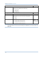
New: 2.6 Hardware Test for buzzer and barcode reader
Modified: Appendix II – support “Field Separator” setting for
EAN-128 with CCD/Laser scan engine
New Word template applied
1.11
New: Appendix V Function Key Mapping
Separate documentation of 5250 Emulator and VT Emulator
2.00
Modified: 3.4.3 WPA Passphrase — supports WPA2-PSK for 8400
Merge documentation of 5250 Emulator and VT Emulator
Company name changed to CIPHERLAB CO., LTD. Since April 2006
Modified: for 8061/8071/8360/8370/8500
CONTENTS
RELEASE NOTES .............................................................................................................................. - 3 INTRODUCTION .................................................................................................................................... 1
System Requirements....................................................................................................................... 2
Features............................................................................................................................................. 2
Getting Started .................................................................................................................................. 3
Alternatives to Download Settings .............................................................................................. 5
Working with Menus & Toolbar ........................................................................................................ 7
File Menu ...................................................................................................................................... 7
Utilities Menu ............................................................................................................................... 7
Telnet Menu.................................................................................................................................. 8
Help Menu .................................................................................................................................... 8
Toolbar .......................................................................................................................................... 9
Special ESC Commands & Hardware Test ....................................................................................10
Special ESC Commands ............................................................................................................ 10
Buzzer Test .................................................................................................................................12
Reader Test ................................................................................................................................ 12
SYSTEM SETTINGS ............................................................................................................................ 13
1.1 Power On ................................................................................................................................... 14
1.1.1 Resume Program ............................................................................................................. 14
1.1.2 Restart Program ............................................................................................................... 14
1.1.3 Auto Power Off..................................................................................................................14
1.2 Security...................................................................................................................................... 14
1.3 Backlight ................................................................................................................................... 15
1.4 Change Prompts & Messages..................................................................................................15
1.5 Macro Frame............................................................................................................................. 16
1.6 Download & Baud Rate ............................................................................................................16
1.7 Key Click.................................................................................................................................... 16
1.8 Reset ......................................................................................................................................... 16
BARCODE SETTINGS.......................................................................................................................... 17
2.1 Barcode Reader........................................................................................................................18
2.1.1 Select Reader Type .......................................................................................................... 18
2.1.2 Configure Reader Settings...............................................................................................18
2.1.3 Configure Symbology Settings.........................................................................................18
2.1.4 Code ID ............................................................................................................................. 18
2.2 RFID Reader..............................................................................................................................19
2.2.1 Data................................................................................................................................... 19
2.2.2 Working Mode .................................................................................................................. 20
2.2.3 Control .............................................................................................................................. 20
2.2.4 Reading Mode .................................................................................................................. 21
2.3 Advanced Settings .................................................................................................................... 22
2.3.1 Input.................................................................................................................................. 22
MIRROR VT Emulator User Guide
2.3.2 Scanner............................................................................................................................. 23
2.3.3 Data................................................................................................................................... 24
2.3.4 Good Read (Good Feedback) ..........................................................................................24
2.3.5 Error Feedback .................................................................................................................25
2.4 Reset ......................................................................................................................................... 26
WIRELESS LAN SETTINGS ................................................................................................................. 27
3.1 Local IP...................................................................................................................................... 28
3.1.1 Enable DHCP Server ........................................................................................................28
3.1.2 Local Name....................................................................................................................... 28
3.1.3 SSID .................................................................................................................................. 28
3.2 Host IP ....................................................................................................................................... 29
3.2.1 Host IP/Name...................................................................................................................29
3.2.2 Telnet Port ........................................................................................................................ 29
3.2.3 Keep Alive ......................................................................................................................... 29
3.3 WLAN Interface ......................................................................................................................... 29
3.4 Security...................................................................................................................................... 29
3.4.1 Open System/Shared Key ...............................................................................................29
3.4.2 WEP Key............................................................................................................................30
3.4.3 WPA-PSK/WPA2-PSK Passphrase ..................................................................................30
3.4.4 EAP .................................................................................................................................... 30
3.5 Login .......................................................................................................................................... 31
3.5.1 Login ................................................................................................................................. 31
3.5.2 Logout ............................................................................................................................... 32
3.5.3 Auto SignOn ...................................................................................................................... 32
3.6 Reset ......................................................................................................................................... 32
EMULATION SETTINGS ...................................................................................................................... 33
4.1 Emulation Type ......................................................................................................................... 34
4.2 Font Size.................................................................................................................................... 34
4.3 Case Conversion .......................................................................................................................34
4.4 Screen Scroll & Control ............................................................................................................35
4.4.1 Navigator .......................................................................................................................... 35
4.4.2 Navigator Key ................................................................................................................... 35
4.4.3 Horizontal Steps ............................................................................................................... 35
4.4.4 Vertical Steps ................................................................................................................... 36
4.4.5 Cursor Tracking ................................................................................................................36
4.4.6 Trim Spaces......................................................................................................................37
4.4.7 Disable Local Echo........................................................................................................... 37
4.4.8 Cursor Flashing ................................................................................................................37
4.4.9 Line Buffer ........................................................................................................................37
4.5 Func Toggle & Function Key Mapping.....................................................................................38
4.5.1 Func Toggle ...................................................................................................................... 38
4.5.2 Keypad Type .....................................................................................................................39
4.5.3 Key Mapping.....................................................................................................................39
4.6 Reset ......................................................................................................................................... 39
SCREEN REFORMATTING .................................................................................................................. 41
5.1 Activate the Screen Reformat Feature....................................................................................41
5.2 Capture Host Session Screens ................................................................................................42
MIRROR VT Emulator User Guide
5.2.1 Logon to Host ...................................................................................................................42
5.2.2 Capture Host Screens ...................................................................................................... 43
5.3 Reformat Host Screens ............................................................................................................44
5.3.1 Host Screen ...................................................................................................................... 44
5.3.2 Terminal Screen ............................................................................................................... 45
5.3.3 Example ............................................................................................................................ 46
GPRS SETTINGS................................................................................................................................. 51
SCAN ENGINE SETTINGS................................................................................................................... 55
Symbologies Supported .................................................................................................................. 55
RFID Tags Supported ...................................................................................................................... 57
CCD/LASER SCAN ENGINE................................................................................................................ 59
Reader Settings Table.....................................................................................................................59
Symbology Settings Table...............................................................................................................60
Code ID Table .................................................................................................................................. 64
LR/ELR LASER SCAN ENGINE ........................................................................................................... 65
Reader Settings Table.....................................................................................................................65
Symbology Settings Table...............................................................................................................66
Code ID Table .................................................................................................................................. 70
2D SCAN ENGINE............................................................................................................................... 71
Reader Settings Table.....................................................................................................................71
Symbology Settings Table...............................................................................................................73
1D Symbologies ......................................................................................................................... 73
2D Symbologies ......................................................................................................................... 78
Code ID Table .................................................................................................................................. 81
8500 ...........................................................................................................................................81
8400 ...........................................................................................................................................82
INTRODUCTION
Seeing the need to combine wireless connectivity and telnet terminal emulation, MIRROR
VT Emulator, also known as CipherNet-VT, is designed to provide telnet terminal
emulation on the 8000/8300/8400/8500 Series Mobile Computers, which are capable of
802.11b/g or GPRS connectivity.
The software, consisting of CipherNet programs (.exe) and the associated runtime (.shx),
is designed for the users to develop custom telnet sessions for the use with the terminal
emulation runtime preloaded on the mobile computers, without spending time writing
any program code. Each of the mobile computers is a telnet client that allows the user to
connect to a host computer, such as an IBM AS/400 server, and make use of the
applications running on it. Thus, the mobile computer works as an input device to a host
computer, and the data collected or input will be sent back to the host computer. On the
other hand, the mobile computer works as an output device as well because it can
display data coming in from the host. Based on the nature that the screen size of the
mobile computer is smaller than that of an actual terminal, CipherNet programs provide a
number of unique features for reformatting host screens.
This manual serves to provide comprehensive understanding of MIRROR VT Emulator,
and helps start a telnet session running host applications. We recommend that you read
the document thoroughly before use and keep it at hand for quick reference.
Thank you for choosing CipherLab products!
1
MIRROR VT Emulator User Guide
SYSTEM REQUIREMENTS
To run the program, one of the Windows operating system is required:
Windows 2000
Windows XP
Windows Vista
Windows 7
FEATURES
CipherNet-VT supports VT100 and VT220 terminal emulation
Can automatically insert data into an input field in the host application via reading
barcodes or RFID tags
2
Easy cloning by saving user settings to a configuration file (.NET)
Supports auto sign on, cursor tracking, etc.
Supports key mapping
Supports control for barcode reader as well as RFID reader
Supports control for beeper and vibrator
Provides font size options
Supports host screen capture and reformatting (Activation key is required!)
Supports quick download by saving download properties to an initial file
Introduction
GETTING STARTED
1) Run CipherNet-VT.exe from the Product CD.
2) Click OK to accept the End-User License Agreement (EULA).
3) Download the runtime program (.SHX) to the mobile computer via Utilities Menu |
Download Program.
Associated Runtime Programs
80xx-VT.SHX
: Download this program file to 8071.
83xx-VT.SHX
: Download this program file to 8330 or 8370.
84xx-VT.SHX
: Download this program file to 8400 or 8470.
85xx-VT.SHX
: Download this program file to 8500, 8570, 8580 or 8590.
On the mobile computer, press [7] + [9] + [Power] simultaneously to enter System
Menu | Load Program.
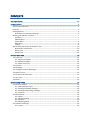
4) Click the drop-down menu of
are working on.
and select the mobile computer you
The associated information and default settings
of the target mobile computer will be displayed
accordingly.
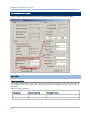
5) Configure the current user settings via Utilities Menu | Configure.
When you are editing an existing or new configuration file, the information and
settings above will be updated accordingly.
3
MIRROR VT Emulator User Guide
6) Save the current user settings to a configuration file via File Menu | Save.
7) Download the configuration file (.NET) to the mobile computer via Utilities Menu |
Download Settings.
Refer to Alternatives to Download Settings.
8) From the CipherNet Runtime Menu on the mobile computer, select 1. Telnet to
start a fresh new telnet session after downloading.
The mobile computer will be associated with an access point and connected to a host.
During the telnet session, you will be able to make use of the host applications after
login. To exit the telnet session, press ESC and FN simultaneously after logging out
properly.
Understanding the Status Icons
On the terminal screen, a number of status icons will be displayed on the bottom
line.
4
Icon
Remark
Special Key
For 8500 Series, individual icons for Shift, Alt and FN indicate a
specific key is pressed.
Navigator
A graphic icon to indicate the relationship between the terminal
screen and the host screen. Refer to 4 Emulation Settings.
Reader
Refer to 2.1 Barcode Reader.
An empty box indicates both readers are disabled.
A flash icon indicates only the RFID reader is enabled.
A barcode icon indicates only the barcode is enabled.
A cross-out barcode icon indicates both the barcode and RFID
readers are enabled.
Antenna
An antenna icon indicates the RF signal strength.
Battery
A battery icon indicates the battery strength.
Introduction
ALTERNATIVES TO DOWNLOAD SETTINGS
Auto-Detect & Download via Cradle-IR, RS-232 or USB Virtual COM
Seat the mobile computer in the cradle or connect it with the RS-232/USB cable to PC. Select to
download settings via Cradle-IR, RS-232 or USB Virtual COM. When the mobile computer is
turned on, it will start to download terminal emulation settings right with the CipherNet
Runtime Menu as long as the current settings on the mobile computer are matching. Otherwise,
you must configure the settings on the mobile computer accordingly.
I P: 12 7. 0. 0. 1
1 .T el ne t
2 .U ti li ti es
S N: EB 70 00 00 1
F
Hot key operation: F3
1. TC P/ IP S et tin gs
2. Em ul at io n Set ti ng s
3. Re ad er T es t
4. Ba ck li gh t
5. Ba tt er y Vo lta ge
6. Se t Da te & Ti me
7. Do wn lo ad _S ett in gs
8. Do wn lo ad
1. In te rf ac e
2. Ba ud R at e
Hot key operation: F1
Hot key operation: F2
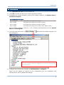
From the CipherNet Runtime Menu on the mobile computer, press F1 directly to enter the
following submenu and select the matching download interface: 2. Utilities Menu | 7.
Download Settings | 1. Interface
From the CipherNet Runtime Menu on the mobile computer, press F2 directly to enter the
following submenu and select the matching baud rate setting: 2. Utilities Menu | 7.
Download Settings | 2. Baud Rate
From the CipherNet Runtime Menu on the mobile computer, press F3 directly to enter the
following submenu and start to download: 2. Utilities Menu | 8. Download
Take the 44-key 8500 mobile computer for example. You need to press FN to enable the
function key, and then press the key for red-coded F1, F2 or F3.
Note: You may press F9 from the CipherNet Runtime Menu to view the current
program version. Press the ESC key to cancel the hot key (F1~F3, F9) operation
and return to the CipherNet Runtime Menu.
5
MIRROR VT Emulator User Guide
Download via IrDA
Pointed the IrDA port on the mobile computer directly to the infrared port of another IR device,
and select to download settings via IrDA. When the mobile computer is turned on, you must
press F3 directly to start to download terminal emulation settings right with the CipherNet
Runtime Menu as long as the current interface setting on the mobile computer is IrDA.
Otherwise, you must press F1 to change the interface on the mobile computer to IrDA first.
6
Introduction
WORKING WITH MENUS & TOOLBAR
The menu bar contains a number of menus that specify which task you want the system
to perform. Each menu contains a list of commands.
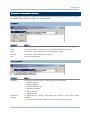
FILE MENU
Command
Action…
New
To create a new configuration file for the telnet client. Refer to each chapter.
Open
To open an existing configuration file. File path needs to be specified.
Save
To save the current settings to a configuration file (.NET).
Save As
To save the current settings to a new file.
Exit
To close the application.
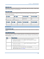
UTILITIES MENU
Command
Action…
Configure
To configure the current user settings. Refer to each chapter.
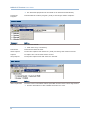
Download
Settings
System Settings
Barcode Settings
Wireless LAN Settings
Emulation Settings
Screen Settings
GPRS Settings
To download the current configuration file (.NET) to the target mobile
computer.
If “Download via USB VCOM” is selected, skip baud rate settings.
7
MIRROR VT Emulator User Guide
Download
Program
The download properties will be saved to an initial file automatically.
To download the runtime program (.SHX) to the target mobile computer.
TELNET MENU
Command
Action…
Connect
To connect to a host.
Click “Save Log” if necessary.
Disconnect
To disconnect with the host.
Start Capture
To start the Capture task with a file (.SCR) for saving host session screens.
Capture
To capture the current host session screen.
Stop Capture
To stop the Capture task and close the .SCR file.
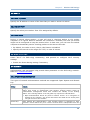
HELP MENU
Command
Action…
About CipherNet
To show version information about CipherNet and End-User License Agreement.
8
Version information is also available from the tree view.
Introduction
TOOLBAR
The toolbar allows quick access to commands that are available in the current stage.
From left to right, they stand for the following commands:
File Menu | New
File Menu | Open
File Menu | Save
Utilities Menu | Configure
Utilities Menu | Download Settings
Telnet Menu | Connect
Telnet Menu | Disconnect
Telnet Menu | Start Capture
Telnet Menu | Capture
Telnet Menu | Stop Capture
Select Product
9
MIRROR VT Emulator User Guide
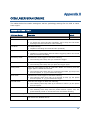
SPECIAL ESC COMMANDS & HARDWARE TEST
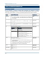
SPECIAL ESC COMMANDS
For VT emulation, a number of special ESC commands are available for system
information and hardware control. You may send an escape sequence from a host to get
device type, serial number, or control the hardware features of the mobile computer.
Feature
Special ESC Command
Supported on
System
Information
ESC[97c
8000/8300/8400/
8500
Device Type
Get device type: ESC[98c
Serial Number
The return value will be ESC[8>’Device Type’\0, such as
[8>8300.
Get serial number: ESC[99c
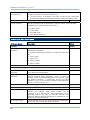
LED
The mobile computer will respond with the information on
H/W, S/N, M/D, KNL, LIB, USR and DEV. Each is separated
by a comma.
The return value will be ESC[9>’Serial Number’\0, such as
[8>EB7000001.
ESC[0;color;mode;duration]
Parameter
Description
color
0: Red LED
8000/8300/
8400/8500
8000/8300/
8400/8500
8000/8300/
8400/8500
1: Green LED
mode & duration
0: LED is turned off for (duration *0.01)
seconds and then turned on
1: LED is turned on for (duration *0.01)
seconds and then turned off
2: LED flashes for (duration *0.01)
seconds and then repeat
Buzzer
ESC[1;beep sequence]
For example, you may send “ESC[1;x;y;x;y…]”.
Reader
A beep sequence refers to pairs of Beep Frequency(x) and
Beep Duration(y).
Beep Frequency = 76000 Hz / Actual Frequency Desired: if
a frequency of 4 KHz is desired, the value of x is 19.
Beep Duration is in units of 10 milliseconds.
Enable: ESC[2;1]
Disable: ESC[2;0]
RFID Reader
Enable: ESC[3;1]
Disable: ESC[3;0]
10
8000/8300/
8400/8500
8000/8300/
8400/8500
8300/8500
Introduction
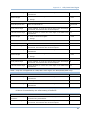
Vibrator
ESC[4;duration]
System Time
The vibrator will work for (duration *0.1) seconds.
ESC[5;YYYYMMDDhhmmss]
8300/8400/ 8500
The mobile computer will reset date and time.
8000/8300/8400/
8500
11
MIRROR VT Emulator User Guide
BUZZER TEST
You can test the buzzer by playing a beep sequence.
1) Turn on the mobile computer. The main menu created by the preloaded CipherNet
Runtime appears.
2) On the mobile computer, select 2. Utilities | 1. TCP / IP Settings.
IP :12 7. 0. 0. 1
1. Tel ne t
2. Uti li ti es
SN :EB 70 00 00 1
F
1 . T CP /I P Se tt in gs
2 .E mu la ti on S et ti ng s
3 . R ea de r Te st
4 .B ac kl ig ht
5 .B at te ry V ol ta ge
6 .S et D at e & Ti me
7 .D ow nl oa d _Se tt in gs
8 .D ow nl oa d
1. Su bn et _ M ask
2. De fa ul t Gat ew ay
3. DH CP S er ver
4. SS ID
5. Te rm in al IP
6. Ho st I P or Na me
7. Te ln et P ort
8. Vi ew S et tin gs
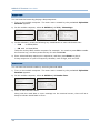
3) In this submenu, press the following key combination to enter the buzzer test:
F10
on 8400/8500
FN + 0
on 8000/8300
Take the 44-key 8500 mobile computer for example. You need to press FN to enable
the function key, and then press the key for red-coded F10.
4) Enter a desired beep sequence or sequences, and then press Enter to play it.
A beep sequence is a pair of frequency-duration, each 2-digit, such as 1520.
READER TEST
You can test the barcode reader by scanning barcode labels.
1) Turn on the mobile computer. The main menu created by the preloaded CipherNet
Runtime appears.
2) On the mobile computer, select 2. Utilities | 3. Reader Test.
IP : 12 7. 0 .0 .1
1. T el ne t
2. U ti li t ie s
SN : EB 70 0 00 01
F
1. TC P /I P S et t in gs
2. Em u la ti o n S et ti n gs
3. Re a de r T es t
4. Ba c kl ig h t
5. Ba t te ry Vo l ta ge
6. Se t D at e & Ti me
7. Do w nl oa d _S e tt in g s
8. Do w nl oa d
3) Start to scan barcode labels.
Along with the read data or error message on the terminal screen, there will be a
beep to indicate Good Read or Error.
12
Chapter 1
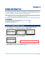
SYSTEM SETTINGS
On this property page, system settings of the mobile computer can be changed.
Once the configuration file (.NET) has been downloaded to the mobile computer, the new
settings will take effect immediately and become the defaults. However, you still can
change many of the settings directly on the mobile computer via CipherNet Runtime
Menu or System Menu:
CipherNet Runtime Menu — Press the Power key on the mobile computer.
Backlight
CipherNet Runtime Menu | 2. Utilities | 4. Backlight
Baud Rate
CipherNet Runtime Menu | 2. Utilities | 7. Download Settings | 1.
Interface 2. Baud Rate
Download via
CipherNet Runtime Menu | 2. Utilities | 8. Download
13
MIRROR VT Emulator User Guide
System Menu — Press 7, 9 and the Power key simultaneously on the mobile computer.
Backlight
System Menu | 2. Settings | 2. Backlight Period
Power On
System Menu | 2. Settings | 3. Auto Off
System Menu | 2. Settings | 4. Power On Options
Key Click
System Menu | 2. Settings | 5. Key Click
IN THIS CHAPTER
1.1
1.2
1.3
1.4
1.5
1.6
1.7
1.8
Power On..................................................................
Security ...................................................................
Backlight ..................................................................
Change Prompts & Messages .......................................
Macro Frame .............................................................
Download & Baud Rate ...............................................
Key Click ..................................................................
Reset .......................................................................
14
14
15
15
16
16
16
16
1.1 POWER ON
1.1.1 RESUME PROGRAM
By default, the mobile computer will start from the latest telnet session at the time it is
turned off.
1.1.2 RESTART PROGRAM
If selected, the mobile computer will start from the CipherNet Runtime Menu.
1.1.3 AUTO POWER OFF
By default, the mobile computer will be automatically turned off when no operation is
taking place within 180 seconds.
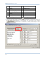
1.2 SECURITY
For security concerns, you may specify a password and select the check box of one or
more tasks that need security checking. By default, no password is required for any task.
If any task is selected and provided with a password, you will not be allowed to enter an
associated menu on the mobile computer without the password. This can prevent
unauthorized users from changing the application settings.
A password can be up to 8 alphanumeric characters.
Note: The password is case-sensitive.
14
Chapter 1
System Settings
Security Option
Remark
TCP / IP Settings
If selected and provided with a password, you will not be allowed to
enter the following menu on the mobile computer unless the correct
password is entered:
CipherNet Runtime Menu | 2. Utilities | 1. TCP/IP Settings
Emulation Settings
If selected and provided with a password, you will not be allowed to
enter the following menu on the mobile computer unless the correct
password is entered:
CipherNet Runtime Menu | 2. Utilities | 2. Emulation Settings
Set Date & Time
If selected and provided with a password, you will not be allowed to
enter the following menu on the mobile computer unless the correct
password is entered:
CipherNet Runtime Menu | 2. Utilities | 6. Set Date & Time
Utilities Menu
If selected and provided with a password, you will not be allowed to
enter the following menu on the mobile computer unless the correct
password is entered:
CipherNet Runtime Menu | 2. Utilities
1.3 BACKLIGHT
By default, the backlight for the LCD and the keypad of the mobile computer is turned
off.
When the backlight is turned on, you may specify a period of idle time so that it can
be automatically turned off. Such time-out is specified in the range of 1~9, in units of
10 seconds. The default time-out is 20 seconds.
1.4 CHANGE PROMPTS & MESSAGES
Re-define the prompts and messages, if necessary.
1) Click the drop-down menu to select among the groups of prompts and messages.
Modify them within a maximum length of 15 or 20 characters, depending on the
screen size; otherwise, they will be automatically truncated.
2) Save the current user settings to a configuration file via File Menu | Save.
3) Download the configuration file (.NET) to the mobile computer via Utilities Menu |
Download Settings.
From the CipherNet Runtime Menu on the mobile computer, select 2. Utilities | 8.
Download.
Note: CipherNet-VT does not support multiple languages; however, you may still choose
to apply a large or small font size.
15
MIRROR VT Emulator User Guide
1.5 MACRO FRAME
Specify a macro frame if necessary. When starting a telnet session, the mobile computer
will send a string of characters upon request from the server.
1.6 DOWNLOAD & BAUD RATE
Click the drop-down menu to select a desired communications setting for the mobile
computer to download the runtime and configuration file (*.NET).
Remark
Download Option
Download via
8000/8300/8500:
If USB-VCOM is selected, it is not necessary to configure the
Baud Rate settings.
8400:
Baud Rate
By default, the baud rate setting is 115200 bps. However, it
will be ignored by USB-VCOM.
1.7 KEY CLICK
By default, the mobile computer will produce an audible signal when you press any key
on the keypad, except for the SCAN key. Cancel the check box if such feedback is not
desired.
1.8 RESET
Click Reset to load the default settings.
Note: The current system settings will be cleared.
16
Chapter 2
BARCODE SETTINGS
According to the requirements of a specific application, you may enable or disable any of
the barcode symbologies and configure its associated parameters.
Supported barcodes depend on the scan engine integrated on the mobile computer.
IN THIS CHAPTER
2.1
2.2
2.3
2.4
Barcode Reader .........................................................
RFID Reader .............................................................
Advanced Settings .....................................................
Reset .......................................................................
18
19
22
26
17
MIRROR VT Emulator User Guide
2.1 BARCODE READER
2.1.1 SELECT READER TYPE
Select a reader type that matches the hardware configuration of your mobile computer.
The associated barcode reader settings, as well as the barcode parameters (= symbology
settings) will be displayed accordingly.
For more information, refer to the following appendixes:
Appendix I – Scan Engine Settings for information on the symbologies and RFID tags
supported.
Appendix II – CCD/Laser Scan Engine provides information on the reader settings as
well as symbology settings for the CCD or Laser scan engine.
Appendix III – LR/ELR Laser Scan Engine provides information on the reader settings
as well as symbology settings for the Long Range Laser or Extra Long Range Laser
scan engine.
Appendix IV – 2D Scan Engine provides information on the reader settings as well as
symbology settings for the 2D scan engine.
Note: If you accidentally selected the wrong reader type and downloaded the settings to
the mobile computer, the mobile computer will use the defaults for the correct
reader type instead.
2.1.2 CONFIGURE READER SETTINGS
Depending on the barcode reader selected, configure the associated reader settings.
Refer to the Reader Settings Table in Appendixes II ~ IV.
2.1.3 CONFIGURE SYMBOLOGY SETTINGS
Depending on the barcode reader selected, configure the associated symbologies. Refer
to the Symbology Settings Table in Appendixes II ~ IV. For a symbology along with the
button
, it means advanced symbology settings are available.
2.1.4 CODE ID
Depending on the barcode reader selected, configure Code ID settings. Refer to the Code
ID Table in Appendixes II ~ IV.
18
Chapter 2
Barcode Settings
2.2 RFID READER
By
default,
the
RFID
reader
is
enabled
to
read
UID
only.
Click
the
button
to configure the associated settings.
2.2.1 DATA
Read UID
By default, the RFID reader is set to read tag UID (Unique Identification).
UID: a permanent factory programmed unique identification (UID) code which is unique to
each tag.
Read Data
Select the check box so that RFID data can be read.
If only partial data is required, specify the start position and maximum length.
Use Delimiter
Select the check box and specify a delimiter to separate UID from data when both are read.
Click the editing box and select one character from the Grid Control (ASCII codes).
Delay before Re-read
By default, the RFID reader is set to re-read the same tag by an interval of 0.4 second when the
tag is not removed out of range.
You may specify a delay time before re-read in the range of 1~9999, in units of 100
milliseconds.
19
MIRROR VT Emulator User Guide
2.2.2 WORKING MODE
Toggle
In this mode, only one reader can work at a time: either RFID or barcode reader.
Control Options
Working with the Switch Key
Always Enabled
The RFID reader is enabled after login; however, it will not work
until you press the switch key.
To stop it from working, press the switch key again.
By ESC Command
The RFID reader is disabled after login. It will not work until you
send the ESC command to activate it and then press the switch key.
The escape sequence for VT emulation is ESC[3;1].
To stop it from working, press the switch key again.
Hybrid (=dual mode)
By default, the RFID reader is always enabled and co-exists with the barcode reader, which is also
called “dual mode” because both readers can work at the same time.
2.2.3 CONTROL
If Toggle is selected, you must select a switch key from the drop-down menu.
Always Enable
By default, the RFID reader is always enabled after login.
By ESC Command
If selected, the RFID reader is disabled after login. You must send the ESC command to enable it.
Switch Key
The switch key works as the toggle of readers. When you press it on the mobile computer, only
one reader is allowed to work at a time.
By default, the switch key is disabled.
Select the switch key (FN+0 ~ FN+9). The selected combination will become unavailable on
the Function Key Mapping list. For example, if you select FN+5, you will find the key
combination mapped to “SwitchKey” in the Function Key Mapping on the Emulation tab.
Note: For VT emulation, you may send an escape sequence from a host to get device
type, serial number, or control the hardware features of the mobile computer.
Refer to Special ESC Commands & Hardware Test.
20
Chapter 2
Barcode Settings
2.2.4 READING MODE
Trigger
If selected, you may press the trigger to start each RFID reading.
When working mode is set “Hybrid”, you can press the trigger to read an RFID tag or a
barcode label depending on which one first comes in range.
Continuous
By default, the RFID reader works in a continuous way. It will keep on reading the same RFID tag
until the tag is removed out of range.
21
MIRROR VT Emulator User Guide
2.3 ADVANCED SETTINGS
These settings are provided to enhance the read operation via the barcode reader.
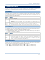
2.3.1 INPUT
Check Leading Code
The leading code refers to the digit in the start position of a barcode. Select the check box to
verify the barcode input. When the leading code is found mismatching, the barcode will be
discarded.
Below are some examples.
Leading code
Barcode scanned
Transaction record
9
9876543210
9876543210
2
9876543210
(Discarded: code not matching)
22
Chapter 2
Barcode Settings
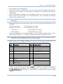
Check Code Length
By default, the maximum barcode length is 15. Select the check box so that it will perform a
length check on the barcode according to the length setting. When the barcode is found longer
than the specified length, it will be discarded.
Read Partial Barcode
By default, it will return the whole barcode that has been decoded. Select the check box so that it
will return partial barcode according to the settings of the start position and maximum length.
Below are some examples.
Start position
Max. length
Barcode scanned
Transaction record
2
10
9876543210
876543210
2
3
9876543210
876
Read partial code + Check leading code:
Start position
Max. length
Leading Code
Barcode scanned
Transaction record
2
7
8
9876543210
8765432
2
7
9
987654321
(Discarded)
2.3.2 SCANNER
Always Enable After Login
The barcode reader is always enabled after login because the scan engine detected is enabled by
default.
Controlled by ESC Command
If selected, the barcode reader is suspended and must be controlled by ESC commands. Instead of
using the default ESC commands or special commands, you may specify an ESC command in the
following format — ESC then left bracket, followed by two numeric characters, and must end with a
lower-case letter (a ~ z).
Option
Escape Sequence
Enable
You need to send one of the following ESC commands to enable it:
Instead of the default ESC[99h, specify an ESC command if necessary.
Special ESC Command — ESC[2;1]
Disable
To stop it from working, send one of the following ESC commands:
Instead of the default ESC[99l, specify an ESC command if necessary.
Auto Enter
Ignore this option if you already have the Auto Enter function enabled for
data processing. Refer to 2.3.3 Data.
Special ESC Command — ESC[2;0]
You may also specify an escape sequence for automatically adding a
carriage return to the end of each scan (= Scan+ENTER).
23
MIRROR VT Emulator User Guide
Feedback Controlled by ESC Command
By default, only a pair of beep sequence is used to indicate a successful decoding of barcode. You
may specify vibrator duration or have LED flashing as well. Otherwise, select the check box if you
wish to send an escape sequence from the host to control the buzzer, vibrator, and LED light.
Proceed to Good Feedback and Error Feedback. You may specify an escape sequence to signal
a good read or error.
Note: For VT emulation, you may send an escape sequence from a host to get device
type, serial number, or control the hardware features of the mobile computer.
Refer to Special ESC Commands & Hardware Test.
2.3.3 DATA
Add Prefix Code
Select the check box to prefix a code to the input data. Click the editing box next to it, and select
one or more codes from the Grid Control (ASCII codes). For example, you may add a dollar sign
“$” to the front of the input data for price information.
Add Suffix Code
Select the check box to suffix a code to the input data. Click the editing box next to it, and select
one or more codes from the Grid Control (ASCII codes).
Note: You may use prefix/suffix code to wrap the input data.
Auto Enter
By default, a carriage return will be automatically added to the end of the barcode input (=
Scan+ENTER). It can then directly proceed to next task upon completion of data input without
requiring you to press the Enter key on the mobile computer. For barcode scanning, it proves to
be timesaving.
Character Replacement
Up to two sets of character replacement are allowed. You may specify to replace a target character
with another character. When the target character is found in the barcode data, it will
automatically be replaced by the specified character.
2.3.4 GOOD READ (GOOD FEEDBACK)
When data is successfully read, the mobile computer may inform you by issuing a beep,
vibrating, or flashing LED light.
Command
Specify the escape sequence to signal a good read. Click the editing box and select from the Grid
Control.
24
Chapter 2
Barcode Settings
Beep Sequence
A beep sequence refers to pairs of Beep Frequency(x) and Beep Duration(y). You may specify
whether or not to have a beep when decoding of a barcode is done successfully.
You may specify pairs of “x y” other than the default “0E 05”. Click the editing box and select
from the Grid Control.
Vibrator
Specify how long the vibrator is turned on (in units of 0.1 second) to indicate a barcode has been
read successfully.
By default, the vibrator is turned off.
LED Flashing
You may specify whether or not to have green LED indication when decoding of a barcode is done
successfully.
By default, the LED indication is disabled.
2.3.5 ERROR FEEDBACK
When an error occurs, the mobile computer may inform you by issuing a beep, vibrating,
or flashing LED light.
Command
Specify the escape sequence to signal an error. Click the editing box and select from the Grid
Control.
Beep Sequence
A beep sequence refers to pairs of Beep Frequency(x) and Beep Duration(y). You may specify
whether or not to have a warning beep to notify that an error occurs while reading a barcode.
You may specify pairs of “x y” other than the default “1E 07 00 05 1E 07”. Click the editing box
and select from the Grid Control.
Vibrator
Specify how long the vibrator is turned on (in units of 0.1 second) to notify that an error occurs
while reading a barcode.
By default, the vibrator is turned off.
LED Flashing
You may specify whether or not to have red LED indication to notify that an error occurs while
reading a barcode.
By default, the LED indication is disabled.
25
MIRROR VT Emulator User Guide
2.4 RESET
Click Reset to load the default settings. This applies to the following settings —
Reader Settings
Barcode & Parameters
Advanced Settings
RFID Settings
Note: The current settings will be cleared.
26
Chapter 3
WIRELESS LAN SETTINGS
To establish a telnet connection to a host, WLAN networking settings must be configured
correctly.
Once the configuration file (.NET) has been downloaded to the mobile computer, the new
settings will take effect immediately and become the defaults. However, you still can
change many of the settings directly on the mobile computer via CipherNet Runtime
Menu or System Menu:
CipherNet Runtime Menu — Press the Power key on the mobile computer.
IP
CipherNet Runtime Menu | 2. Utilities | 1. TCP/IP Settings
Host
CipherNet Runtime Menu | 2. Utilities | 1. TCP/IP Settings
Wi-Fi Setting: Power Saving
CipherNet Runtime Menu | 2. Utilities | 1. TCP/IP Settings
Login
CipherNet Runtime Menu | 2. Utilities | 2. Emulation Settings
27
MIRROR VT Emulator User Guide
System Menu — Press 7, 9 and the Power key simultaneously on the mobile computer.
IP
System Menu | 8. Next Page | 3. Wi-Fi Menu | 2. Network Setting
System Menu | 8. Next Page | 3. Wi-Fi Menu | 3. WLAN Setting
Security
System Menu | 8. Next Page | 3. Wi-Fi Menu | 4. Security
IN THIS CHAPTER
3.1
3.2
3.3
3.4
3.5
3.6
Local IP ....................................................................
Host IP.....................................................................
WLAN Interface .........................................................
Security ...................................................................
Login .......................................................................
Reset .......................................................................
28
29
29
29
31
32
3.1 LOCAL IP
3.1.1 ENABLE DHCP SERVER
By default, DHCP server is enabled and all the settings can be obtained from it.
If DHCP server is disabled, you must provide the following information —
Subnet Mask
Gateway
DNS Server
Terminal IP
3.1.2 LOCAL NAME
You may enter a name for identifying the mobile computer.
3.1.3 SSID
This refers to Service Set ID or Identifier, which serves to uniquely identify a group of
wireless network devices used in a given “Service Set”. For example, you need to specify
the same SSID here as is used for access points so that the mobile computer can
associate to the access points.
Note: SSID can be made up of 32 characters maximum.
28
Chapter 3
Wireless LAN Settings
3.2 HOST IP
3.2.1 HOST IP/NAME
Specify the IP address or name of the host that you wish to access via telnet.
3.2.2 TELNET PORT
Specify the telnet port number. Port 23 is assigned by default.
3.2.3 KEEP ALIVE
During a normal telnet session, a host will send a checking packet to the mobile
computer on a regular basis to maintain the connection. However, the host you access
might not be configured to keep the session alive. In that case, you can have the mobile
computer automatically send a checking packet to the host at intervals.
By default, the value is set 0; that is, this feature is disabled.
Specify the interval in the range of 0~255, in units of minute.
3.3 WLAN INTERFACE
Select “Wi-Fi” for 802.11b/g connectivity, and proceed to configure Wi-Fi security
settings.
Enable the Power Saving setting if necessary.
3.4 SECURITY
Authentication and encryption help provide data protection on the 802.11b/g network.
Refer to 3.3 WLAN Interface.
3.4.1 OPEN SYSTEM/SHARED KEY
Two types of network authentication methods are supported: Open System and Shared
Key.
Setting
Remark
Open System
Using Open authentication, any wireless station can request authentication. The
station that needs to authenticate with another wireless station sends an
authentication management frame that contains the identity of the sending
station. The receiving station or AP will grant any request for authentication.
Shared Key
Open authentication allows any device network access. If no encryption is
enabled on the network, any device that knows the SSID of the access point
can gain access to the network.
Using Shared Key authentication, each wireless station is assumed to have
received a secret shared key over a secure channel that is independent from the
29
MIRROR VT Emulator User Guide
802.11b/g wireless network communications channel.
Shared key authentication requires that the client configure a static WEP key.
The client access will be granted only if it passed a challenge based
authentication.
Note: For Shared Key authentication, the active WEP key is used for authentication.
3.4.2 WEP KEY
Select the check box to implement Wired Equivalent Privacy or Wireless Encryption
Protocol (WEP) for data encryption.
Setting
Remark
Key Length
Encryption type can be 64 bits (5 bytes) or 128 bits (13 bytes).
Using 64-bit encryption, the password phrase can be 5 characters long.
From the Grid Control, select up to 5 characters (ASCII codes) for the WEP
key.
For 128-bit encryption, the password phrase can be 13 characters long.
From the Grid Control, select up to 13 characters (ASCII codes) for the WEP
key.
Key 1 ~ 4
Key index number. Up to four WEP keys can be configured.
Active
Only one key (the active one) can be used at a time.
Note: You must use the same settings as configured for other devices on your wireless
network, e.g. access points.
3.4.3 WPA-PSK/WPA2-PSK PASSPHRASE
WPA-PSK is supported to enhance security over wireless networks, and this Pre-Shared
key mode requires a passphrase to access the network. The passphrase must be 8 to 63
characters (ASCII codes). It is used to generate a WEP key automatically.
For 8400, it also supports WPA2-PSK!
3.4.4 EAP
Select the check box to enable authentication using Extensible Authentication Protocol
(EAP). It requires user name and password so that the mobile computer can identify
itself when associating to Cisco® access points.
Setting
Remark
Identity
Specify a user name. (32 characters maximum)
Password
Specify a password. (32 characters maximum)
30
Chapter 3
Wireless LAN Settings
3.5 LOGIN
To successfully log on to a host, the following settings must be specified correctly.
Note: After logging out properly, press ESC and FN (the function key) simultaneously to
disconnect with the host and return to the main menu.
3.5.1 LOGIN
Normally, the cursor will stay on the “Username” field waiting for input during a fresh
new telnet session. Instead of using the arrow keys to move the cursor to the “Password”
input field, you may press the function key or key combination mapped to “Tab”. For
example, you may map the physical Tab key to “Tab” for 8500 Series. Refer to 4.5 Func
Toggle & Function Key Mapping.
Setting
Remark
Username,
Specify username and password for logging on to the host you wish to access.
Password
Shortcut Key
By default, the shortcut keys are disabled. You will have to enter the username
and password manually.
Select the shortcut keys (FN+0 ~ FN+9) so that you can enter the text string
for Username and Password by two strokes. Each selected key combination
will become unavailable on the Function Key Mapping list. For example, if you
select FN+0 for “Username” and FN+1 for “Password”, you will find them
mapped to “Name Key” and “Password Key” individually in the Function Key
Mapping on the Emulation tab.
Note: Use the shortcut keys to enter the text string for Username/Password by two
strokes. For this feature to work properly, Username/Password must be specified
correctly.
PROMPT FOR USERNAME/PASSWORD
Specify the prompt strings that request you to enter username and password. They must
be exactly the same as received from the host. Refer to 3.5.3 Auto SignOn.
Note: If any of the prompt strings of the host system exceeds 20 characters, you will fail
to sign on automatically.
31
MIRROR VT Emulator User Guide
3.5.2 LOGOUT
The logout command depends on the host applications. In order to exit the specific host
application, you will have to send the correct command as required.
Setting
Remark
Logout
Specify the logout command that allows you to log off the host. It must be exactly
the same string as displayed on the host screen.
Shortcut Key
By default, the shortcut keys are disabled. You will have to enter the logout
command manually.
Select the shortcut keys (FN+0 ~ FN+9). The selected key combination will
become unavailable on the Function Key Mapping list. For example, if you
select FN+2, you will find it mapped to “Exit Key” in the Function Key Mapping
on the Emulation tab.
Note: For this feature to work properly, the logout string must be specified correctly.
After logging out properly, press ESC and FN (the function key) simultaneously to
disconnect with the host and return to the main menu.
3.5.3 AUTO SIGNON
By default, this feature is disabled. The host will request Username and Password every
time the mobile computer attempts to log on.
If this feature is supported by the host, select the check box so that the mobile
computer can be allowed to automatically log on to the host. Refer to 3.5.1 Login.
Note: For this feature to work properly, Username/Password and each prompt string
must be specified correctly and cannot exceed 20 characters.
3.6 RESET
Click Reset to load the default settings.
Note: The current settings will be cleared.
32
Chapter 4
EMULATION SETTINGS
To successfully emulate a VT terminal, emulation settings must be configured correctly.
Once the configuration file (.NET) has been downloaded to the mobile computer, the new
settings will take effect immediately and become the defaults. However, you still can
change many of the settings directly on the mobile computer via CipherNet Runtime
Menu or System Menu:
CipherNet Runtime Menu — Press the Power key on the mobile computer.
Emulation Type
CipherNet Runtime Menu | 2. Utilities | 2. Emulation Settings
Screen Scroll & Control
CipherNet Runtime Menu | 2. Utilities | 2. Emulation Settings
33
MIRROR VT Emulator User Guide
IN THIS CHAPTER
4.1
4.2
4.3
4.4
4.5
4.6
Emulation Type .........................................................
Font Size ..................................................................
Case Conversion ........................................................
Screen Scroll & Control ...............................................
Func Toggle & Function Key Mapping ............................
Reset .......................................................................
34
34
34
35
38
39
4.1 EMULATION TYPE
CipherNet-VT supports VT100 and VT220 terminal emulation.
By default, the emulation type is VT100.
4.2 FONT SIZE
The terminal screen size varies by the mobile computer. Display capability, as shown
below, depends on the screen size as well as the font you use. Refer to 1.4 Change
Prompts & Messages.
Mobile Computer
Small (Font 6x8)
Large (Font 8x16)
8000 Series
16 characters by 8 lines (default)
12 characters by 4 lines
8300 Series
20 characters by 8 lines (default)
15 characters by 4 lines
8400 Series
26 characters by 18 lines (default)
20 characters by 9 lines
8500 Series
26 characters by 19 lines (default)
20 characters by 9 lines
By default, small font (6x8) is applied. Data coming in from the host will be displayed
accordingly. This setting also affects the default horizontal/vertical steps the cursor move
at one time on the host screen.
4.3 CASE CONVERSION
By default, there is no case conversion. Data coming in from the host will be displayed in
letter case matching to the original.
Options include “convert to lower/upper case”. For example, if you select “to lower
case”, data coming in from the host will be converted to lower case; and vice versa.
34
Chapter 4
Emulation Settings
4.4 SCREEN SCROLL & CONTROL
Limited to the actual screen size, the mobile computer can only display a portion of the
host screen. The following features help ease working from the terminal screen.
4.4.1 NAVIGATOR
A navigator can be a graphic icon or miniature window on the terminal screen, indicating
the relationship between the terminal screen and the host screen. A miniature cursor is
blinking to indicate the input position.
Option
Remark
None
Disable the navigator.
Icon
By default, a graphic icon is used for navigation.
Take 8500 Series for example. The icon will appear on the bottom line of the
screen.
20*15
Instead of the small icon, you may select “20*15” or “32*24” for a larger icon.
32*24
Take 8500 Series for example. The icon will take the top few lines of the screen.
4.4.2 NAVIGATOR KEY
The navigator key works as the toggle of navigator. When you press the navigator key on
the mobile computer, it will hide or show the navigator by turns.
On 8300/8400/8500 Series, the navigator key only works when a larger icon (20*15
or 32*24) for navigator is applied.
Option
Remark
Disable
By default, the navigator key is disabled.
FN+0 ~
Select a function key combination for the navigator key.
FN+9
Select the navigator key (FN+0 ~ FN+9). The selected key combination will
become unavailable on the Function Key Mapping list. For example, if you select
FN+6, you will find it mapped to “Navigator Key”.
4.4.3 HORIZONTAL STEPS
Specify how many horizontal steps the cursor will move at a time on the host screen
when you press the following key combinations simultaneously –
FN + Left (for 8300/8400/8500 Series) or FN + “-+$” (for 8000 Series)
FN + Right (for 8300/8400/8500 Series) or FN + “%#•” (for 8000 Series)
35
MIRROR VT Emulator User Guide
4.4.4 VERTICAL STEPS
Specify how many vertical steps the cursor will move at a time on the host screen when
you press the following key combinations simultaneously –
FN + Up
FN + Down
Note: The horizontal and vertical steps are associated with the font size.
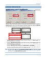
4.4.5 CURSOR TRACKING
This feature is enabled by default. The terminal screen will automatically adjust itself so
that the cursor will always be visible on the screen. Thus, every screen received from the
host will be displayed with the cursor visible to indicate the first input field.
Note: This feature only works when a screen refresh incident occurs on the host.
When you disable the Cursor Tracking feature, the coordinates (0,0) on the terminal
screen are related to (0,0) on the host screen. Thus, every screen received from the host
will be first displayed starting from (0,0) regardless of the cursor.
The relationship between the terminal screen (small) and the host screen (large) is based
on the upper-left point of the screens (see above). The cursor is outside of the terminal
screen. To view the hidden information or locate the cursor, you need to adjust the
terminal screen manually.
36
Chapter 4
Emulation Settings
Horizontal / Vertical Steps
Press the following key combinations simultaneously –
FN + Left (for 8300/8400/8500 Series) or FN + “-+$”
(for 8000 Series)
FN + Right (for 8300/8400/8500 Series) or FN + “%#•” (for 8000 Series)
FN + Up
FN + Down
When the Cursor Tracking feature is enabled, there will be a warning beep to indicate that the
terminal screen has reached the boundaries of the host screen.
Note: For 8500 Series, the above function keys are originally used to adjust LCD
contrast (FN + Up/Down) and backlight intensity (FN + Left/Right). After
logging on to a host, these keys will be used to adjust the terminal screen instead.
That is, you cannot use them to adjust LCD contrast and backlight intensity until
you log out.
Cursor Movement
To move the cursor to a desired input field, press the function key that is mapped to “Tab”.
To move the cursor to a desired input point, press the arrow keys Up, Down, Left, and Right.
4.4.6 TRIM SPACES
Select the check box to make the most use of the terminal screen; unnecessary spaces
will be discarded. Take the following for example.
Original line: ->
Trimmed
1. Set up<-
->1. Set up<-
Note: Spaces between characters will not be discarded.
4.4.7 DISABLE LOCAL ECHO
By default, it will echo typed text locally on the mobile computer.
Select the check box if local echo is not desired.
4.4.8 CURSOR FLASHING
Select the check box to have a flashing cursor.
4.4.9 LINE BUFFER
Select the check box to operate in line buffer mode.
37
MIRROR VT Emulator User Guide
4.5 FUNC TOGGLE & FUNCTION KEY MAPPING
The function key or key combination is one of the keys on the mobile physical keypad
that transmit control codes. Control codes do not produce displayable characters but are
codes for functions. If these codes are received by the mobile computer, it will perform
the associated function as defined.
4.5.1 FUNC TOGGLE
Generally, a function key combination, which requires pressing FN to enter the function
mode, works as follows —
1) Press FN on the 8300/8400/8500 Series mobile computer.
There will be an “F” icon on the screen to indicate the function mode is on.
2) Press the second key to get the value of a key combination (say, press the number
key 1 to get the value of F1). The icon will go off as the function mode is toggled off.
To have the function mode persist, you may choose to lock the function toggle in
advance so that it will not be toggled off automatically.
3) To get the value of another key combination, repeat the above steps.
To abort the function mode, press FN again and the icon will go off.
Note: For 8300/8400/8500 Series, the function key is unlocked by default.
For 8000 Series, the function key only works with the function toggle locked.
Function Toggle
Remark
Unlocked
The function mode is toggled on by pressing the function key.
(also known as Auto Resume It can be toggled off by pressing the second key of the key
mode)
combination.
Locked
The function mode is toggled on by pressing the function key.
(also known as Toggle mode) It can only be toggled off by pressing the function key again.
38
Chapter 4
Emulation Settings
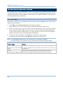
4.5.2 KEYPAD TYPE
The following options for keypad layout are supported for 8300/8400/8500 Series. Select
the matching keypad type first, and map the available function keys to meet your needs.
Mobile Computer
Keypad Type
Remark
8300 Series
8400 Series
44-TE Key is a new option specifically provided for terminal
emulation use!
8500 Series
4.5.3 KEY MAPPING
By default, FN+1 ~ FN+9, FN+0 (or F1 ~ F12 for 8500 44-key) are mapped to F1 ~ F9,
F10 (F1 ~ F12), which are pre-defined as shown below. Click an available function key.
You may change its key combination or re-define key code to meet a specific need.
Note: The function key mapping list varies by the mobile computer and keypad layout. If
a specific key is not available on the physical keypad, its associated key mapping
may not take effect.
For example, the following function keys may be required during a telnet session.
Function Key
Mapped to
Remarks
Any available key
F3
Exit the sign-on request.
Any available key
F12
Cancel a task.
Any available key
Switch Key
See 2.2 RFID Reader
Tab or any other key
Tab
See 3.5.1 Login – Username/Password
Any available key
Name Key
See 3.5.1 Login – Username/Password
Any available key
Password Key
See 3.5.1 Login – Username/Password
Any available key
Exit Key
See 3.5.2 Logout
Any available key
Navigator Key
See 4.4.2 Navigator Key
4.6 RESET
Click Reset to load the default settings.
Note: The current settings will be cleared.
39
MIRROR VT Emulator User Guide
40
Chapter 5
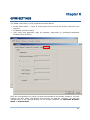
SCREEN REFORMATTING
The screen reformat feature requires you to enable it by entering the activation key on
the mobile computer; otherwise, the screen settings cannot take effect. If you have
received an activation key, proceed with the screen capture task.
Note: CipherLab will issue a unique activation key under the pay-by-use policy. Please
contact your local sales representative for licensing.
IN THIS CHAPTER
5.1 Activate the Screen Reformat Feature........................... 41
5.2 Capture Host Session Screens ..................................... 42
5.3 Reformat Host Screens ............................................... 44
5.1 ACTIVATE THE SCREEN REFORMAT FEATURE
1) Press Power on the mobile computer to enter the CipherNet Runtime Menu.
2) Select 2. Utilities | 2. Emulation Settings |8. Activation Key.
IP :12 7. 0. 0. 1
1. Tel ne t
2. Uti li ti es
SN :EB 70 00 00 1
F
1 . T CP /I P Se tt in gs
2 .E mu la ti on S et ti ng s
3 . R ea de r Te st
4 .B ac kl ig ht
5 .B at te ry V ol ta ge
6 .S et D at e & Ti me
7 .D ow nl oa d _Se tt in gs
8 .D ow nl oa d
1. Em ul at io n T yp e
2. Lo gi n Na me
3. Lo gi n Pa ssw or d
4. Na vi ga to r
5. Ho ri S cr oll S te ps
6. Ve rt S cr oll S te ps
7. Cu rs or T rac ki ng
8. Ac ti va ti on _Ke y
3) Scan the activation barcode (or enter the activation key you received).
4) Return to the main menu and select 1. Telnet.
IP : 12 7 .0 . 0. 1
1. T el n et
2. U ti l it i es
SN : EB 7 00 0 00 1
F
Bottom line reserved for status icons
The mobile computer will be associated with an access point and connected to a host.
A new session will start with reformatted screens. To exit the telnet session, press
ESC and FN simultaneously after logging out properly.
41
MIRROR VT Emulator User Guide
5.2 CAPTURE HOST SESSION SCREENS
5.2.1 LOGON TO HOST
1) Run the CipherNet program on your computer.
2) Click OK to accept the End-User License Agreement (EULA).
3) Connect to the host via Telnet Menu | Connect or click
on the toolbar.
4) Enter the IP address of the host that you wish to access via telnet.
Select the check box of Save Log in case you need to analyze the activities during a
telnet session. The information will be saved to a log file in the “Logs” folder
automatically created in the same directory where the CipherNet program is.
5) Click OK to start connecting to the host. The host system will prompt you to enter
username/password to login as shown below.
6) After login, you may start using the host application you need.
Note: Wireless LAN networking settings must be configured properly.
42
Chapter 5
Screen Reformatting
5.2.2 CAPTURE HOST SCREENS
You may capture screens from the host application using the associated commands via
Telnet Menu or the following icons on the toolbar. A status message will appear on the
left bottom of the CipherNet window, indicating the current status.
1) Click
to start the capture task and save the host screens to a .SCR file.
(Status message: Ready to capture)
2) Click
to capture the current host screen. Skip unnecessary screens.
(Status message: A total of screens that have been captured.)
3) Click
to stop the capture task when you have captured the screens necessary for
the terminal operation during a normal session.
4) Proceed to reformat host screens via Utilities Menu | Configure.
Note: Try to capture all the necessary screens. If you cannot decide which screen to skip
now, capture it. You can always delete it later when the .SCR file is loaded for
screen reformatting.
43
MIRROR VT Emulator User Guide
5.3 REFORMAT HOST SCREENS
The target is to reformat the captured host screens, or pages, so that they can be best
displayed on the terminal screen.
The Screen settings page is divided into two parts: one is a window (left) displaying the
captured host screens for viewing and editing, and the other is the associated forms
(right) for reformatting these pages to fit in the terminal screen.
5.3.1 HOST SCREEN
Load Host Session Screens
Click
to import the screens from a .SCR file. The total of pages, or
screens, is displayed next to the button.
Click on any part of the window. The current position (Row, Column) will be displayed accordingly.
44
Drag the horizontal/vertical scroll bars to view the hidden text of the current page.
Click the four control buttons to change the page currently displayed –
for displaying the first page
for displaying the previous page
for displaying the next page
for displaying the last page
Chapter 5
Screen Reformatting
Delete Current Screen
Click
if the screen currently displayed is not desired for reformatting.
The current number of page, or screen, is displayed next to the button.
Note: If you neither delete nor reformat a captured screen, there will be an empty
screen displayed during a telnet session.
5.3.2 TERMINAL SCREEN
Reformat Page … to
Specify the page format on the terminal screen. You can have different page format for different
host screen.
This setting or its options depend on the font size you use in 4.2 Font Size.
Host (Row, Column)
If the original message of a line does not prompt you to input selection, i.e. no input fields, leave
the host row as “nil”. You may simply rephrase the message. The same for host column; let it
remain 1.
If the original message of a line prompts you to input selection, you need to specify both the host
row and column; otherwise, the host will fail to catch it.
On the Host Screen window, click a desired input point and read its coordinates from the left
bottom of the window. The coordinates are the values for host row and column.
45
MIRROR VT Emulator User Guide
Terminal Screen (Messages)
Copy the necessary messages from the Host Screen window and rephrase them, if necessary, to
fit to the terminal screen.
Line No.
This indicates the line number when the message is displayed on the terminal screen.
Control Buttons
If the total lines of page format setting exceed 8, the two buttons will become available for moving
forward or backward to display the rest lines.
Reset
Click Reset to load the default settings.
Note: The current host screens and settings for reformatting will be cleared after clicking
Reset.
5.3.3 EXAMPLE
46
Chapter 5
Screen Reformatting
You have loaded a total of 4 host screens, and currently work on the first page.
From the Host Screen window (left), you can see there are five message lines and
four empty lines on this page. You may ignore the empty lines and simply skip them
when reformatting.
Copy the necessary messages for reformatting (right). You may need to rephrase
them so that they can best fit in to a terminal screen, which is decided by the page
format of the terminal screen.
Note: Host Row/Column can be ignored if the message is not requesting you to input
information.
From the Host Screen window (left), click on the input point right following the last
message “Please select your task :”. Its coordinates are (9,26).
Copy this message for reformatting (right). You may need to rephrase it as well. For
example, enter “Select:_”. The underline character “_” is used to indicate the
maximum length for input.
Note: Host Row/Column and the maximum length for input must be specified correctly;
otherwise, the host applications will not work properly.
Below shows the messages displayed on the host screen before reformatting, and
those rephrased to be displayed on the terminal screen after reformatting.
Rows
Host Screen
Lines
Terminal Screen
1
(empty)
1
TE Demo
47
MIRROR VT Emulator User Guide
2
Cipherlab
Demo
3
Terminal
Emulation 2
1.Video Shop AP
(empty)
3
2.Book Store AP
4
1. Video Shop Application
4
3.Quit
5
2. Book Store Application
5
Select:_
6
3. Quit this demo program
6
7
(empty)
7
8
(empty)
8
9
Please select your task :
9
(before reformatting)
(after reformatting)
Proceed to next host screen by clicking
at the bottom of Host Screen window. If
a host screen is not desired for reformatting, you must delete it by clicking
session.
48
; otherwise, it will become an empty screen during a telnet
Chapter 5
Screen Reformatting
Now proceed to the second page.
From the Host Screen window (left), you can see there are six message lines and four
empty lines on this page. You may ignore the empty lines and simply skip them for
reformatting.
Copy the necessary messages for reformatting (right). You may need to rephrase
them so that they can best fit in to a terminal screen, which is decided by the page
format of the terminal screen.
Note: Host Row/Column can be ignored if the message is not requesting you to input
information.
From the Host Screen window (left), click on the input point right following the four
message:
“Code of the video :”
- Its coordinates are (4,20).
“Name of the movie :”
-
“
Retail price
“
Total quantity
Its coordinates are (5,20).
:”
:”
-
Its coordinates are (6,20).
-
Its coordinates are (7,20).
Copy the messages for reformatting (right). You may need to rephrase them as well.
The underline character “_” is used to indicate the maximum length for input.
Note: Host Row/Column and the maximum length for input must be specified correctly;
otherwise, the host applications will not work properly.
Below shows the messages displayed on the host screen before reformatting, and
those rephrased to be displayed on the terminal screen after reformatting.
Rows
Host Screen
Lines
Terminal Screen
1
(empty)
1
Video Shop AP
2
Video Shop Application
2
Code:__________
3
(empty)
3
Name:__________
4
Code of the video :
4
Price:_____
5
Name of the movie :
5
Qty:_____
6
[Q/q]= Exit
6
Retail price
7
:
Total quantity :
8
(empty)
9
(empty)
10
[ Q/q ] = Exit
(before reformatting)
7
8
9
(after reformatting)
Proceed to next host screen by clicking
at the bottom of Host Screen window. If
a host screen is not desired for reformatting, you must delete it by clicking
session.
; otherwise, it will become an empty screen during a telnet
49
MIRROR VT Emulator User Guide
50
Chapter 6
GPRS SETTINGS
The GPRS connectivity is only supported for 8500 Series.
Access Point Name — name of access point that connects the mobile network to the
Internet
IP address (DHCP or static)
User name and password (may be optional, depending on Challenge-Handshake
Authentication Protocol)
Once the configuration file (.NET) has been downloaded to the mobile computer, the new
settings will take effect immediately and become the defaults. However, you still can
change many of the settings directly on the mobile computer via CipherNet Runtime
Menu or System Menu:
51
MIRROR VT Emulator User Guide
CipherNet Runtime Menu — Press the Power key on the mobile computer.
GPRS Settings
CipherNet Runtime Menu | 2. Utilities | 1. TCP/IP Settings
System Menu — Press 7, 9 and the Power key simultaneously on the mobile computer.
Access Point Name
System Menu | 8. Next Page | 3. GSM/GPRS Menu | 3. GPRS
Settings
Enter PIN Code
System Menu | 8. Next Page | 3. GSM/GPRS Menu | 2. Security
CHAP Authentication
System Menu | 8. Next Page | 3. GSM/GPRS Menu | 3. GPRS
Settings
DHCP
System Menu | 8. Next Page | 3. GSM/GPRS Menu | 3. GPRS
Settings
Note: Please contact your Internet service provider (ISP) or network operator for
information on GPRS related settings.
If you are using 8580 or 8590 with SIM card installed properly, select the check box to
enable GPRS first. Then, give PIN code for SIM card and other information necessary for
establishing a GPRS connection.
52
Chapter 6
GPRS Settings
Item
Remark
Access Point Name
Required
PIN Code
Required if not using default
CHAP User Name & Password
Depends on CHAP authentication setting
IP Address, dynamic or static
Required; provide a static IP if DHCP is disabled
53
MIRROR VT Emulator User Guide
54
Appendix I
SCAN ENGINE SETTINGS
The MIRROR Terminal Emulator allows configuring the following reader types,
depending on the module equipped on your mobile computer:
8000
8300
8400
8500
Barcode Reader
1D CCD Scan Engine
1D Laser Scan Engine
1D Long Range Laser Scan Engine (LR)
1D Extra Long Range Laser Scan Engine (ELR)
2D Scan Engine
RFID Reader
ACG_RFID Module v0.9
ACG_RFID Module v1.0
Options of different reader combination are allowed, such as 1D+RFID and 2D+RFID. For
each combination, both readers can be initialized and ready for scanning at the same
time (dual mode operation). For example, if you press the SCAN button while running
the CipherNet run-time program on the mobile computer, it will read a barcode in
position or an RFID tag in proximity depending on which one comes first.
Note: You cannot have 1D+2D scan engines installed on the mobile computer because
they are both barcode readers!
SYMBOLOGIES SUPPORTED
Varying by the scan engine installed, the supported symbologies or tag types are listed
below. For details on configuring associated settings, please refer to each Appendix
separately.
CCD, Laser
LR, ELR
2D
Codabar
Code 11
8300Note
Note: Code 11 is supported on Long Range Laser scan engine for 8300 only.
Code 93
Composite Code
MSI
55
MIRROR VT Emulator User Guide
Plessey
Postal Codes
Telepen
Code 128
Code 128
GS1-128 (EAN-128)
ISBT 128
Code 2 of 5
Industrial 25 (Discrete 25)
Interleaved 25
Matrix 25
8400Note
Chinese 25
8400Note
Coop 25Note
Note: (1) Matrix 25 and Chinese 25 are supported on 2D scan engine for 8400 only.
(2) Coop 25 is supported on CCD/Laser scan engine for 8000/8300/8400 only.
Code 3 of 9
Code 39
Trioptic Code 39
Italian Pharmacode (Code 32)
French Pharmacode
EAN/UPC
EAN-8
EAN-13
Bookland EAN (ISBN)
UPC-E0
UPC-E1
UPC-A
GS1 DataBar
(RSS)
GS1 DataBar Omnidirectional (RSS-14)
GS1 DataBar Truncated
GS1 DataBar Stacked
GS1 DataBar Stacked Omnidirectional
GS1 DataBar Limited (RSS Limited)
GS1 DataBar Expanded (RSS Expanded)
GS1 DataBar Expanded Stacked
2D Symbologies
PDF417
MicroPDF417
Data Matrix
Maxicode
QR Code
56
Appendix I
Scan Engine Settings
RFID TAGS SUPPORTED
The RFID reader supports read/write operations depending on the tags. The supported
labels include ISO 15693, Icode®, ISO 14443A, and ISO 14443B. Currently, the
performance of some tags has been confirmed, and the results are listed below for your
reference. The results found with RFID module version 1.0 are different from those found
with version 0.9 or older versions.
Note: You should study the specifications of RFID tags before use.
ACG_RFID Module Version 1.0
ISO 14443A
UID Only
Read Page
Write Page
---
---
---
---
SRF55V02P
---
---
SRF55V02S
---
---
SRF55V10P
---
---
Read Page
Write Page
Mifare Standard 1K
---
---
Mifare Standard 4K
---
---
Mifare DESFire
---
---
Mifare S50
---
---
SLE44R35
---
---
SLE66R35
---
---
---
---
Mifare Standard 1K
Mifare Standard 4K
Mifare Ultralight
Mifare DESFire
Mifare S50
SLE44R35
SLE66R35
ISO 14443B
SRIX 4K
SR176
ISO 15693
ICODE SLI
TI Tag-it HF-I
ICODE®
(Phillips)
ICODE
ACG_RFID Module Version 0.9
ISO 14443A
ISO 15693
UID Only
ICODE SLI
SRF55V02P
SRF55V02S
57
MIRROR VT Emulator User Guide
SRF55V10P
TI Tag-it HF-I
ST LRI64
ST LRI512
Tagit®
Tagit
ICODE®
(Phillips)
ICODE
58
Appendix II
CCD/LASER SCAN ENGINE
The tables below list reader settings as well as symbology settings for the CCD or Laser
scan engine.
READER SETTINGS TABLE
CCD/Laser Engine
Description
Scan Mode
Continuous Mode
Laser mode
Non-stop scanning
Test Mode
None
The scanning won't stop until (a) a barcode is read or (b) the preset
timeout expires.
Press the scan trigger to start with scanning.
Read Redundancy
The scanning won't stop until (a) a barcode is read, (b) the preset
timeout expires, or (c) you release the trigger.
Press the scan trigger to start with scanning.
Auto Power Off Mode
The scanning won't stop until (a) a barcode is decoded, (b) the pre-set
timeout expires, or (c) you release the trigger.
Hold down the scan trigger to start with scanning.
Auto Off Mode
The scanning won't stop until you press the trigger again.
Press the scan trigger to aim at a barcode. Within one second, press the
trigger again to decode the barcode.
Laser Mode
The scanning won't stop until you release the trigger.
Press the scan trigger to start with scanning.
Aiming Mode
Capable of re-transmitting barcode data if triggering within one second
after a successful decoding
Hold down the scan trigger to start with scanning.
Alternate Mode
Capable of decoding the same barcode repeatedly
Non-stop scanning
Momentary Mode
To decode the same barcode repeatedly, move away the scan beam
and target it at the barcode for each scanning.
Non-stop scanning
Repeat Mode
Default
The scanning won't stop until the preset timeout expires, and, the
preset timeout period re-counts after each successful decoding.
None
No redundancy means one successful decoding will make the reading valid
and induce the "READER Event".
59
MIRROR VT Emulator User Guide
One time, Two times, The higher the reading security is (that is, the more redundancy the user
or Three times
selects), the slower the reading speed gets.
If "Three Times" is selected, it will take a total of four consecutive
successful decodings of the same barcode to make the reading valid.
Time-out
3 sec.
0~255 (second)
Set the maximum time for decoding to continue during a scan attempt.
It applies to the following scan modes only –
Aiming mode
Laser mode
Auto Off mode
Auto Power Off mode
SYMBOLOGY SETTINGS TABLE
CCD/Laser Engine
Description
Codabar
Transmit
Character
Default
Enable
Start/Stop Decide whether to include the start/stop characters in the No
data being transmitted.
If "Transmit Start/Stop Characters" is desired, select one
set:
abcd / abcd
abcd / tn*e
ABCD / ABCD
ABCD / TN*E
Code 128
Enable
GS1-128 (EAN-128)
Enable
Transmit Code ID (for Decide whether to include Code ID (“]C1”) will be included No
EAN-128)
in the data being transmitted.
Replace
Separator
Field Decide whether to replace the field separator. If the No
barcode contains Field Separator “0x1D”, it will be
changed to the desired Field Separator. For example, type
the desired character “;” (semicolon) as the new field
separator. Then if the barcode contains Field Separator
“0x1D”, it will be changed to “;”.
ISBT 128
Enable
Industrial 25 (Discrete 25)
Enable
Start/Stop Selection
This decides the readability of all 2 of 5 symbology Industrial 25
variants. For example, flight tickets actually use an
Industrial 2 of 5 barcode but with Interleaved 2 of 5
start/stop pattern. In order to read this barcode, the
start/stop pattern selection parameter of Industrial 2 of 5
should set to "Interleaved 25".
Verify Check Digit
Decide whether to verify the check digit. If the check digit No
is incorrect, the barcode will not be accepted.
60
Appendix II
CCD/Laser Scan Engine
Transmit Check Digit
Decide whether to include the check digit in the data being Yes
transmitted.
Select Length
One or two fixed lengths
1~127
Range
Interleaved 25
Enable
Start/Stop Selection
Refer to Industrial 25.
Verify Check Digit
Decide whether to verify the check digit. If the check digit No
is incorrect, the barcode will not be accepted.
Transmit Check Digit
Decide whether to include the check digit in the data being Yes
transmitted.
Select Length
One or two fixed lengths
Interleaved
25
1~126
Range
Matrix 25
Disable
Start/Stop Selection
Refer to Industrial 25.
Verify Check Digit
Decide whether to verify the check digit. If the check digit No
is incorrect, the barcode will not be accepted.
Transmit Check Digit
Decide whether to include the check digit in the data being Yes
transmitted.
Select Length
One or two fixed lengths
Matrix 25
1~127
Range
Coop 25
Disable
Verify Check Digit
Decide whether to verify the check digit. If the check digit No
is incorrect, the barcode will not be accepted.
Transmit Check Digit
Decide whether to include the check digit in the data being Yes
transmitted.
Note: Coop 25 is supported on CCD/Laser scan engine for 8000/8300/8400 only.
French Pharmacode
Transmit Check Digit
Disable
Decide whether to include the check digit in the data being Yes
transmitted.
Italian Pharmacode (Code 32)
Transmit Check Digit
Disable
Decide whether to include the check digit in the data being Yes
transmitted.
Note: For French/Italian Pharmacode, “Transmit Start/Stop Character” is not provided in
UI but it is controlled by the same setting of Code 39.
Code 39
Transmit
Character
Enable
Start/Stop Decide whether to include the start/stop characters "*" in No
the data being transmitted.
Verify Check Digit
Decide whether to verify the check digit. If the check digit No
is incorrect, the barcode will not be accepted.
61
MIRROR VT Emulator User Guide
Transmit Check Digit
Decide whether to include the check digit in the data being Yes
transmitted.
Code 39 Full ASCII
Code 39 Full ASCII includes all the alphanumeric and Disable
special characters.
Code 93
Enable
MSI
Disable
Select one of the three calculation formulas to verify the Single Modulo
check digit. If the check digit is incorrect, the barcode will 10
not be accepted.
Verify Check Digit
Transmit Check Digit
Double Modulo 10
Modulo 11 & 10
Decide whether to include the check digit in the data being Both
digits
transmitted.
transmitted
Select Length
Single Modulo 10
Last digit not transmitted
Both digits transmitted
Both digits not transmitted
One or two fixed lengths
1~127
Range
Negative Barcode
Disable
Plessey
Disable
Convert to UK Plessey
When applied, each occurrence of the character "A" in the No
barcode data will be replaced by the character "X".
Transmit Check Digit
Decide whether to include the two check digits in the data Yes
being transmitted.
Telepen
Original
(Numeric)
Disable
Telepen The original Telepen includes numeric characters.
AIM
Telepen
ASCII)
No
(Full AIM Telepen (Full ASCII) includes all the alphanumeric and Yes
special characters.
GS1 DataBar-14 (RSS-14)
Disable
GS1 DataBar-14 is short for GS1 DataBar Omnidirectional. This group consists of (1) GS1 DataBar
Omnidirectional, (2) GS1 DataBar Truncated, (3) GS1 DataBar Stacked, and (4) GS1 DataBar
Stacked Omnidirectional.
Transmit Code ID
Decide whether to include Code ID ("]e0") will be included Yes
in the data being transmitted.
Transmit Application
ID
Decide whether to include the Application ID ("01") in the Yes
data being transmitted.
Transmit Check Digit
Decide whether to include the check digit in the data being Yes
transmitted.
GS1 DataBar Limited (RSS Limited)
Disable
Transmit Code ID
Yes
62
Refer to RSS-14.
Appendix II
CCD/Laser Scan Engine
Transmit Application
ID
Refer to RSS-14.
Yes
Transmit Check Digit
Refer to RSS-14.
Yes
GS1 DataBar Expanded (RSS Expanded)
Disable
This group consists of (1) GS1 DataBar Expanded, and (2) GS1 DataBar Expanded Stacked.
Transmit Code ID
Refer to RSS-14.
EAN-8
Yes
Enable
Convert to EAN-13
The EAN-8 barcode will be expanded into EAN-13, and the No
next processing will follow the settings configured for
EAN-13.
Transmit Check Digit
Decide whether to include the check digit in the data being Yes
transmitted.
Addon 2 / Addon 5
Decide whether to decode EAN-8 with addons.
EAN-13 / UPC-A
No
Enable
ISBN Conversion
The EAN-13 barcode starting with 978 and 979 will be No
converted to ISBN.
ISSN Conversion
The EAN-13 barcode starting with 977 will be converted to No
ISSN.
GTIN for EAN-13
The EAN-13 barcode will be expanded into 14-digit Global No
Trade Item Number (GTIN).
Transmit Check Digit
Decide whether to include the check digit in the data being Yes
transmitted.
Addon 2 / Addon 5
Decide whether to decode EAN-13/UPC-A with addons.
(UPC-A)
EAN-13
Convert
(UPC-A)
Check Digit
No
to The UPC-A barcode will be expanded into EAN-13, and the Yes
next processing will follow the settings configured for
EAN-13.
Transmit Decide whether to include the UPC-A check digit in the Yes
data being transmitted.
(UPC-A)
Transmit Decide whether to include the UPC-A System Number in Yes
System Number
the data being transmitted.
UPC-E
Enable
Convert to UPC-A
The UPC-E barcode will be expanded into UPC-A, and the No
next processing will follow the settings configured for
UPC-A.
Transmit Check Digit
Decide whether to include the UPC-E check digit in the Yes
data being transmitted.
Transmit
Number
Enable UPC-E1
System Decide whether to include the UPC-E System Number in No
the data being transmitted.
Decide whether to decode both UPC-E0 and UPC-E1 No
barcodes.
By default, it decodes the UPC-E0 barcodes only.
63
MIRROR VT Emulator User Guide
Enable UPC-E1 Triple Decide whether to apply read redundancy to the UPC-E1 No
Check
barcode.
Addon 2 / Addon 5
When applied, the same UPC-E1 barcode has to be
read three times to make a valid reading. This is
helpful when the barcode is defaced and requires more
attempts to read it successfully.
Decide whether to decode UPC-E with addons.
No
CODE ID TABLE
Code ID Options
Set 1
Set 2
Set 3
Set 4
Set 5
Code 39
A
C
Y
M
A
Italian Pharmacode
A
C
Y
M
A
French Pharmacode
A
C
Y
M
A
Industrial 25
C
H
H
H
S
Interleaved 25
D
I
Z
I
S
Matrix 25
E
G
G
G
S
Codabar
F
N
X
N
F
Code 93
I
L
L
L
G
Code 128
H
K
K
K
C
ISBT 128
H
K
K
K
C
UPC-E
S
E
C
E
E
EAN-8
P
B
B
FF
E
EAN-13
M
A
A
F
E
UPC-A
J
A
A
A
E
MSI
V
V
D
P
M
Plessey
W
W
E
Q
P
Telepen
Z
---
---
---
---
64
Appendix III
LR/ELR LASER SCAN ENGINE
The tables below list reader settings as well as symbology settings for the Long Range
Laser (LR) or Extra Long Range Laser (ELR) scan engine.
READER SETTINGS TABLE
LR/ELR Engine
Description
Scan Mode
Continuous Mode
Laser mode
Non-stop scanning
Test Mode
The scanning won't stop until (a) a barcode is decoded, (b) the pre-set
timeout expires, or (c) you release the trigger.
Hold down the scan trigger to start with scanning.
Auto Off Mode
The scanning won’t stop until you press the trigger again.
Press the scan trigger to aim at a barcode. Within one second, press the
trigger again to decode the barcode.
Laser Mode
Capable of decoding the same barcode repeatedly
Press the scan trigger to start with scanning.
Aiming Mode
To decode the same barcode repeatedly, move away the scan beam
and target it at the barcode for each scanning.
Non-stop scanning
Alternate Mode
The scanning won't stop until (a) a barcode is read, (b) the preset
timeout expires, or (c) you release the trigger.
Press the scan trigger to start with scanning.
The scanning won’t stop until (a) a barcode is read or (b) the preset
timeout expires.
Aiming Duration
0~255 (second)
Default
3 sec.
Set the maximum time for decoding to continue during a scan attempt.
It applies to Aiming mode only.
65
MIRROR VT Emulator User Guide
SYMBOLOGY SETTINGS TABLE
LR/ELR Engine
Description
Default
Codabar
Transmit
Character
Disable
Start/Stop Decide whether to include the start/stop characters in the No
data being transmitted.
Select Length
Any Length
Any Length
One or two fixed lengths
Range (1~55)
Code 128
Enable
GS1-128
Enable
Replace
Separator
Field Decide whether to replace the field separator. If the No
barcode contains Field Separator “0x1D”, it will be
changed to the desired Field Separator. For example, type
the desired character “;” (semicolon) as the new field
separator. Then if the barcode contains Field Separator
“0x1D”, it will be changed to “;”.
ISBT 128
Enable
Industrial 25 (Discrete 25)
Enable
Select Length
Any Length
Any Length
One or two fixed lengths
Range (1~55)
Interleaved 25
Convert to EAN-13
Enable
Convert a 14-character barcode into EAN-13
following requirements are met:
Verify Check Digit
if
the No
The barcode must have a leading 0 and a valid EAN-13
check digit.
Decide whether to verify the check digit. If desired, select No
one of the algorithms below. If the check digit is incorrect,
the barcode will not be accepted.
No
USS algorithm
OPCC algorithm
Transmit Check Digit
Decide whether to include the check digit in the data being No
transmitted.
Select Length
Any Length
Any Length
One or two fixed lengths
Range (1~55)
Code 39
Enable
Convert to Code 32
Convert to Italian Pharmacode.
Verify Check Digit
Decide whether to verify the check digit. If the check digit No
is incorrect, the barcode will not be accepted.
66
No
Appendix III LR/ELR Laser Scan Engine
Transmit Check Digit
Decide whether to include the check digit in the data being No
transmitted.
"Verify Check Digit" must be enabled so that the check
digit can be left out (= "Transmit Check Digit"
disabled).
Code 39 Full ASCII
Code 39 Full ASCII includes all the alphanumeric and Disable
special characters.
Trioptic Code 39
Decide whether to decode Trioptic Code 39.
Select Length
Trioptic Code 39 is a variant of Code 39 used in the
marking of computer tape cartridges. It always
contains six characters.
Any Length
Any Length
One or two fixed lengths
Range (1~55)
Code 93
Select Length
Disable
Any Length
Any Length
One or two fixed lengths
Range (1~55)
MSI
Verify Check Digit
Disable
Disable
If Two Check Digits option is selected, an additional Single Modulo
verification is required to ensure integrity. Select one of 10
the algorithms below. If the check digit is incorrect, the
barcode will not be accepted.
Check Digit
Algorithm
One Check Digit
Single Modulo 10
Two Check Digits
Mod 10/Mod 11
Mod 10/Mod 10
Transmit Check Digit
Decide whether to include the check digit in the data being No
transmitted.
Select Length
GS1 DataBar (RSS)
GS1 Databar-14
GS1 Databar Limited
Any Length
Any Length
One or two fixed lengths
Range (1~55)
---
GS1 DataBar-14 is short for GS1 DataBar Omnidirectional. Enable
This group consists of (1) GS1 DataBar Omnidirectional,
(2) GS1 DataBar Truncated, (3) GS1 DataBar Stacked, and
(4) GS1 DataBar Stacked Omnidirectional.
Enable
GS1 Databar Expanded This group consists of (1) GS1 DataBar Expanded, and (2) Enable
GS1 DataBar Expanded Stacked.
67
MIRROR VT Emulator User Guide
Convert
UPC/EAN
RSS
to "Convert to UPC/EAN" only applies to GS1 Databar-14 and No
GS1 Databar Limited barcodes not decoded as part of a
Composite barcode.
Convert to EAN-13
Strip the leading "010" from barcodes.
"01" is the Application ID and must be followed by a
single zero (the first digit encoded)
Convert to UPC-A
Strip the leading "0100" from barcodes.
"01" is the Application ID and must be followed by
two or more zeros (but not six zeros)
EAN-8
Enable
Convert to EAN-13
The EAN-8 barcode will be expanded into EAN-13, and the No
next processing will follow the settings configured for
EAN-13.
Addon 2 / Addon 5
Refer to UPC/EAN Addon setting.
EAN-13
Enable
Bookland EAN (ISBN)
The EAN-13 barcode starting with 978 will be converted to No
ISBN.
Addon 2 / Addon 5
Refer to UPC/EAN Addon setting.
UPC-A
Enable
Transmit Check Digit
Decide whether to include the UPC-A check digit in the Yes
data being transmitted.
Transmit Preamble
Decide whether to include the UPC-A preamble System System
Number (and Country Code) in the data being transmitted. Number
Addon 2 / Addon 5
Refer to UPC/EAN Addon setting.
UPC-E0
Enable
Transmit Check Digit
Decide whether to include the UPC-E0 check digit in the Yes
data being transmitted.
Transmit Preamble
Decide whether to include the UPC-E0 preamble System System
Number (and Country Code) in the data being transmitted. Number
Addon 2 / Addon 5
Refer to UPC/EAN Addon setting.
Convert to UPC-A
The UPC-E0 barcode will be expanded into UPC-A, and the No
next processing will follow the settings configured for
UPC-A.
UPC-E1
Disable
Transmit Check Digit
Decide whether to include the UPC-E1 check digit in the Yes
data being transmitted.
Transmit Preamble
Decide whether to include the UPC-E1 preamble System System
Number (and Country Code) in the data being transmitted. Number
Addon 2 / Addon 5
Refer to UPC/EAN Addon setting.
68
Appendix III LR/ELR Laser Scan Engine
Convert to UPC-A
The UPC-E1 barcode will be expanded into UPC-A, and the No
next processing will follow the settings configured for
UPC-A.
UCC Coupon Extended Code
Disable
Read UPC-A barcodes starting with digit "5", EAN-13 barcodes starting with digits "99", and
UPC-A/EAN-128 Coupon Codes.
UPC-A, EAN-13, and EAN-128 must be enabled first!
UPC/EAN Addon
Addon 2 / Addon 5
--Decide whether to decode
UPC-E1, UPC-A with addons.
Select Length
EAN-13,
UPC-E0, Ignore...
Ignore Addons
Decode Only With Addons
Decode With Addons (= Auto-discriminate)
Code 11
Verify Check Digit
EAN-8,
Enable
Decide whether to verify the check digit. If the check digit No
is incorrect, the barcode will not be accepted.
No verification
One Check Digit
Two Check Digits
Any Length
Any Length
One or two fixed lengths
Range (1~55)
Note: Code 11 is supported on Long Range Laser scan engine for 8300 only.
69
MIRROR VT Emulator User Guide
CODE ID TABLE
Code ID Options
Set 1
Set 2
Set 3
Set 4
Set 5
Codabar
F
N
X
N
F
Industrial 25
C
H
H
H
S
Interleaved 25
D
I
Z
I
S
Code 39
A
C
Y
M
A
Trioptic Code 39
A
C
Y
M
X
Code 93
I
L
L
L
G
Code 128
H
K
K
K
C
Italian Pharmacode
A
C
Y
M
A
MSI
V
V
D
P
M
EAN-8
P
B
B
FF
E
EAN-13
M
A
A
F
E
UPC-A
J
A
A
A
E
UPC-E
S
E
C
E
E
70
Appendix IV
2D SCAN ENGINE
The tables below list reader settings as well as symbology settings for the 2D scan
engine.
READER SETTINGS TABLE
2D Engine
Description
Scan Mode
Continuous Mode
Laser mode
Non-stop scanning
Test Mode
Far Focus
Far Focus – optimized to read at its far position
Near Focus – optimized to read at its near position
Smart Focus – toggles the focus position after every
frame
Decide whether to flash illumination on every barcode On
capture to aid decoding.
Aiming Pattern
The scanning won't stop until (a) a barcode is read or (b) the preset
timeout expires.
Select the focus mode to control the working range:
Decode Illumination
The scanning won't stop until (a) a barcode is read, (b) the preset
timeout expires, or (c) you release the trigger.
Press the scan trigger to start with scanning.
Focus Mode
The scanning won't stop until (a) a barcode is decoded, (b) the pre-set
timeout expires, or (c) you release the trigger.
Hold down the scan trigger to start with scanning.
Auto Off Mode
The scanning won't stop until you press the trigger again.
Press the scan trigger to aim at a barcode. Within one second, press the
trigger again to decode the barcode.
Laser Mode
Capable of decoding the same barcode repeatedly
Press the scan trigger to start with scanning.
Aiming Mode
To decode the same barcode repeatedly, move away the scan beam
and target it at the barcode for each scanning.
Non-stop scanning
Alternate Mode
Default
Turn On (Internal LED)
Turn Off
Decide whether to project the aiming pattern during On
barcode capture.
Turn On
Turn Off
71
MIRROR VT Emulator User Guide
Time-out
0~255 (second)
3 sec.
Set the maximum time for decoding to continue during a scan attempt.
It applies to the following scan modes only –
Aiming mode
Laser mode
Auto Off mode
Aiming Duration
3 sec.
1~255 (second)
Set the maximum time for aiming to continue before a scan attempt.
Picklist Mode
Picklist mode enables the decoder to decode only barcodes Disable
aligned under the center of the laser aiming pattern.
1D Inverse Decode
Enable
Disable
1D Inverse Decoder:
Decode regular 1D barcode only
Decode inverse 1D barcode only
Decode
regular
1D
barcode only
Decode both regular and inverse
Note: (1) Focus Mode is supported on 2D scan engine for 8500 only.
(2) Picklist Mode and 1D Inverse Decoding are supported on 2D scan engine for
8400 only.
72
Appendix IV
2D Scan Engine
SYMBOLOGY SETTINGS TABLE
1D SYMBOLOGIES
2D Engine
Description
Default
Codabar
Transmit
Character
Disable
Start/Stop Decide whether to include the start/stop characters in the No
data being transmitted.
Select Length
Any Length
Any Length
One or two fixed lengths
Range (1~55)
Code 128
Enable
GS1-128
Enable
Replace
Separator
Field Decide whether to replace the field separator. If the No
barcode contains Field Separator “0x1D”, it will be
changed to the desired Field Separator. For example, type
the desired character “;” (semicolon) as the new field
separator. Then if the barcode contains Field Separator
“0x1D”, it will be changed to “;”.
ISBT 128
Enable
Industrial 25 (Discrete 25)
Enable
Select Length
Any Length
Any Length
One or two fixed lengths
Range (1~55)
Interleaved 25
Convert to EAN-13
Enable
Convert a 14-character barcode into EAN-13
following requirements are met:
Verify Check Digit
if
the No
The barcode must have a leading 0 and a valid EAN-13
check digit.
Decide whether to verify the check digit. If desired, select No
one of the algorithms below. If the check digit is incorrect,
the barcode will not be accepted.
No
USS algorithm
OPCC algorithm
Transmit Check Digit
Decide whether to include the check digit in the data being No
transmitted.
Select Length
Any Length
Any Length
One or two fixed lengths
Range (1~55)
73
MIRROR VT Emulator User Guide
Matrix 25
Disable
Verify Check Digit
Decide whether to verify the check digit. If the check digit No
is incorrect, the barcode will not be accepted.
Transmit Check Digit
Decide whether to include the check digit in the data being No
transmitted.
Select Length
Any Length
Any Length
One or two fixed lengths
Range (1~55)
Chinese 25
Disable
Note: Matrix 25 and Chinese 25 are supported on 2D scan engine for 8400 only.
Code 39
Enable
Convert to Code 32
Convert to Italian Pharmacode.
Verify Check Digit
Decide whether to verify the check digit. If the check digit No
is incorrect, the barcode will not be accepted.
Transmit Check Digit
Decide whether to include the check digit in the data being No
transmitted.
No
"Verify Check Digit" must be enabled so that the check
digit can be left out (= "Transmit Check Digit"
disabled).
Code 39 Full ASCII
Code 39 Full ASCII includes all the alphanumeric and Disable
special characters.
Trioptic Code 39
Decide whether to decode Trioptic Code 39.
Select Length
Trioptic Code 39 is a variant of Code 39 used in the
marking of computer tape cartridges. It always
contains six characters.
Any Length
MSI
Verify Check Digit
74
Any Length
One or two fixed lengths
Range (1~55)
Code 93
Select Length
Disable
Disable
Any Length
Any Length
One or two fixed lengths
Range (1~55)
Disable
If Two Check Digits option is selected, an additional Single Modulo
verification is required to ensure integrity. Select one of 10
the algorithms below. If the check digit is incorrect, the
barcode will not be accepted.
Appendix IV
Check Digit
Algorithm
One Check Digit
Single Modulo 10
Two Check Digits
2D Scan Engine
Mod 10/Mod 11
Mod 10/Mod 10
Transmit Check Digit
Decide whether to include the check digit in the data being No
transmitted.
Select Length
Any Length
One or two fixed lengths
Range (1~55)
GS1 DataBar (RSS)
GS1 Databar-14
Any Length
--GS1 DataBar-14 is short for GS1 DataBar Omnidirectional. Enable
This group consists of (1) GS1 DataBar Omnidirectional,
(2) GS1 DataBar Truncated, (3) GS1 DataBar Stacked, and
(4) GS1 DataBar Stacked Omnidirectional.
GS1 Databar Limited
Enable
GS1 Databar Expanded This group consists of (1) GS1 DataBar Expanded, and (2) Enable
GS1 DataBar Expanded Stacked.
Convert
UPC/EAN
RSS
to "Convert to UPC/EAN" only applies to GS1 Databar-14 and No
GS1 Databar Limited barcodes not decoded as part of a
Composite barcode.
Convert to EAN-13
Strip the leading "010" from barcodes.
"01" is the Application ID and must be followed by a
single zero (the first digit encoded)
Convert to UPC-A
Strip the leading "0100" from barcodes.
"01" is the Application ID and must be followed by
two or more zeros (but not six zeros)
EAN-8
Enable
Convert to EAN-13
The EAN-8 barcode will be expanded into EAN-13, and the No
next processing will follow the settings configured for
EAN-13.
Addon 2 / Addon 5
Refer to UPC/EAN Addon setting.
EAN-13
Enable
Bookland EAN (ISBN)
The EAN-13 barcode starting with 978 will be converted to No
ISBN.
Addon 2 / Addon 5
Refer to UPC/EAN Addon setting.
UPC-A
Transmit Check Digit
Enable
Decide whether to include the UPC-A check digit in the Yes
data being transmitted.
75
MIRROR VT Emulator User Guide
Transmit Preamble
Decide whether to include the UPC-A preamble System System
Number (and Country Code) in the data being transmitted. Number
Addon 2 / Addon 5
Refer to UPC/EAN Addon setting.
UPC-E0
Enable
Transmit Check Digit
Decide whether to include the UPC-E0 check digit in the Yes
data being transmitted.
Transmit Preamble
Decide whether to include the UPC-E0 preamble System System
Number (and Country Code) in the data being transmitted. Number
Addon 2 / Addon 5
Refer to UPC/EAN Addon setting.
Convert to UPC-A
The UPC-E0 barcode will be expanded into UPC-A, and the No
next processing will follow the settings configured for
UPC-A.
UPC-E1
Disable
Transmit Check Digit
Decide whether to include the UPC-E1 check digit in the Yes
data being transmitted.
Transmit Preamble
Decide whether to include the UPC-E1 preamble System System
Number (and Country Code) in the data being transmitted. Number
Addon 2 / Addon 5
Refer to UPC/EAN Addon setting.
Convert to UPC-A
The UPC-E1 barcode will be expanded into UPC-A, and the No
next processing will follow the settings configured for
UPC-A.
UCC Coupon Extended Code
Disable
Read UPC-A barcodes starting with digit "5", EAN-13 barcodes starting with digits "99", and
UPC-A/EAN-128 Coupon Codes.
UPC-A, EAN-13, and EAN-128 must be enabled first!
UPC/EAN Addon
Addon 2 / Addon 5
--Decide whether to decode
UPC-E1, UPC-A with addons.
Select Length
76
EAN-13,
UPC-E0, Ignore...
Ignore Addons
Decode Only With Addons
Decode With Addons (= Auto-discriminate)
Code 11
Verify Check Digit
EAN-8,
Disable
Decide whether to verify the check digit. If the check digit No
is incorrect, the barcode will not be accepted.
No verification
One Check Digit
Two Check Digits
Any Length
One or two fixed lengths
Range (1~55)
Any Length
Appendix IV
2D Scan Engine
Postal Codes
---
US Postnet
Enable
US Planet
Enable
Transmit US
Check Digit
Postal US Postnet or US Planet must be enabled first!
UK Postal
Transmit UK
Check Digit
Enable
Enable
Postal UK Postal must be enabled first!
Enable
Japan Postal
Enable
Australian Postal
Enable
Dutch Postal
Enable
UPU FICS Postal
Disable
USPS 4CB/One Code/
Disable
Intelligent Mail
Note: UPU FICS Postal and USPS 4CB/One Code/ Intelligent Mail are supported on 2D
scan engine for 8400 only.
Composite Codes
Disable
Composite CC-C
Disable
Composite CC-A/B
Disable
Composite TLC-39
Enable
GS1-128 Emulation
Mode for UCC/EAN
Composite Codes
Transmit UCC/EAN Composite Code data as if it was Disable
encoded in GS1-128 barcodes.
UPC Composite Mode
Always
UPC barcodes can be "linked" with a 2D barcode during UPC
Linked
transmission as if they were one barcode.
UPC Never Linked
Transmit UPC barcodes regardless of whether a 2D
barcode is detected.
UPC Always Linked
Transmit UPC barcodes and the 2D portion. If the 2D
portion is not detected, the UPC barcode will not be
transmitted.
CC-A/B or CC-C must be enabled!
Auto-discriminate UPC Composites
Transmit UPC barcodes as well as the 2D portion if
present.
77
MIRROR VT Emulator User Guide
2D SYMBOLOGIES
2D Engine
Description
Default
2D Symbologies
---
PDF417
Enable
MicroPDF417
Enable
Data Matrix
Enable
Data Matrix Inverse
Decide whether to decode Data Matrix Inverse.
Regular Only
Regular Only
Decode regular Data Matrix barcodes only.
Inverse Only
Decode inverse Data Matrix barcodes only.
Inverse Autodetect
Decode both regular and inverse Data Matrix barcodes.
Mirror Image (for Data Decide whether to decode mirror image Data Matrix Never
Matrix)
barcodes.
Never
Do not decode Data Matrix barcodes that are mirror
images.
Always
Decode only Data Matrix barcodes that are mirror
images.
Auto
Decode both mirrored and unmirrored Data Matrix
barcodes.
Maxicode
Enable
QR Code
Enable
QR Code Inverse
Decide whether to decode QR Code Inverse.
Regular Only
Decode regular QR Code only.
Inverse Only
Decode inverse QR Code only.
Inverse Autodetect
Decode both regular and inverse QR Code.
78
Regular Only
Appendix IV
2D Scan Engine
MicroQR
Enable
Aztec
Enable
Aztec Inverse
Decide whether to decode Aztec Inverse.
Regular Only
Regular Only
Decode regular Aztec barcodes only.
Inverse Only
Decode inverse Aztec barcodes only.
Inverse Autodetect
Decode both regular and inverse Aztec barcodes.
Note: Data Matrix Mirror, MicroQR, Aztec, and 2D Inverse are supported on 2D scan
engine for 8400 only.
2D Symbologies - Macro PDF
---
Macro PDF is a special feature for concatenating multiple PDF barcodes into one file, known as
Macro PDF417 or Macro MicroPDF417.
Transmit/Decode Mode Decide how to handle Macro PDF decoding.
Passthrough
All Symbols
Buffer All Symbols / Transmit Macro PDF When Complete
Transmit all decoded data from an entire Macro PDF
sequence only when the entire sequence is scanned and
decoded. If the decoded data exceeds the limit of 50
symbols, no transmission because the entire sequence
was not scanned!
Transmit Any Symbol in Set / No Particular Order
Transmit data from each Macro PDF symbol as decoded,
regardless of the sequence.
Passthrough All Symbols
Transmit and decode all Macro PDF symbols and
perform no processing. In this mode, the host is
responsible for detecting and parsing the Macro PDF
sequences.
ESC Characters
When enabled, it uses the backslash "\" as an Escape None
character for systems that can process transmissions
containing special data sequences. It will format special
data according to the Global Label Identifier (GLI)
protocol, which only affects the data portion of a Macro
PDF symbol transmission. The Control Header, if enabled,
is always sent with GLI formatting.
79
MIRROR VT Emulator User Guide
Note: When printing barcodes, keep each Macro PDF sequence separate, as each has a
unique identifier. Do not mix barcodes from several Macro PDF sequences, even if
they encode the same data. When you scan Macro PDF sequences, scan the entire
Macro PDF sequence without interruption!
80
Appendix IV
2D Scan Engine
CODE ID TABLE
8500
Code ID Options
Set 1
Set 2
Set 3
Set 4
Set 5
Codabar
F
N
X
N
F
Industrial 25
C
H
H
H
S
Interleaved 25
D
I
Z
I
S
Code 39
A
C
Y
M
A
Trioptic Code 39
A
C
Y
M
X
Code 93
I
L
L
L
G
Code 128
H
K
K
K
C
Italian Pharmacode
A
C
Y
M
A
MSI
V
V
D
P
M
EAN-8
P
B
B
FF
E
EAN-13
M
A
A
F
E
UPC-A
J
A
A
A
E
UPC-E
S
E
C
E
E
Code 11
K
J
J
D
H
Composite Code (CC-A/B, CC-C)
L
X
M
J
La
Composite TLC-39
O
Z
O
R
L2
US Postnet
h
a
s
i
X
US Planet
i
b
t
j
X
UK Postal
j
c
u
k
X
Japan Postal
k
d
v
l
X
Australian Postal
l
e
w
m
X
Dutch Postal
m
f
x
n
X
PDF417
a
O
W
T
L
MicroPDF417
b
P
V
U
L
Data Matrix
c
Q
U
V
d
Maxicode
d
R
T
W
U
QR Code
e
S
S
X
Q
Macro PDF417
p
i
a
q
L
Macro MicroPDF417
q
j
b
r
L
81
MIRROR VT Emulator User Guide
8400
Code ID Options
Set 1
Set 2
Set 3
Set 4
Set 5
Codabar
F
N
X
N
F
Industrial 25
C
H
H
H
S
Interleaved 25
D
I
Z
I
S
Matrix 25
E
G
G
G
S
Chinese 25
Q
M
P
S
X
Code 39
A
C
Y
M
A
Trioptic Code 39
A
C
Y
M
X
Code 93
I
L
L
L
G
Code 128
H
K
K
K
C
ISBT 128
H
K
K
K
C
Italian Pharmacode
A
C
Y
M
A
MSI
V
V
D
P
M
EAN-8
P
B
B
FF
E
EAN-13
M
A
A
F
E
UPC-A
J
A
A
A
E
UPC-E
S
E
C
E
E
Code 11
K
J
J
D
H
Composite Code (CC-A/B, CC-C)
L
X
M
J
La
Composite TLC-39
O
Z
O
R
L2
US Postnet
h
a
s
i
X
US Planet
i
b
t
j
X
UK Postal
j
c
u
k
X
Japan Postal
k
d
v
l
X
Australian Postal
l
e
w
m
X
Dutch Postal
m
f
x
n
X
USPS 4 CB / One Code / Intelligent Mail
n
g
y
o
X
UPU FICS Postal
o
h
z
p
X
PDF417
a
O
W
T
L
MicroPDF417
b
P
V
U
L
Data Matrix
c
Q
U
V
d
Maxicode
d
R
T
W
U
QR Code
e
S
S
X
Q
MicroQR
f
T
R
Y
Q
82
Appendix IV
2D Scan Engine
Aztec
g
U
Q
Z
z
IATA
z
z
r
h
S
Macro PDF417
p
i
a
q
L
Macro MicroPDF417
q
j
b
r
L
83