1
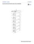
MG-MICA MULTIPURPOSE GRID AND ACCESSORIES
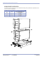
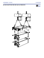
4. USING THE MG-MICA MULTIPURPOSE GRID TO FLY MICA LOUDSPEAKER ARRAYS
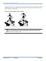
MG-MICA GRID WITH MICA LOUDSPEAKERS IN FORWARD POSITION FOR
MAXIMUM DOWNTILT
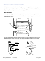
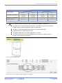
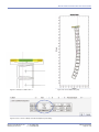
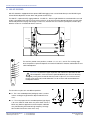
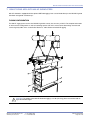
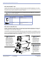
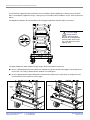
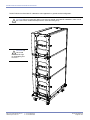
MICA loudspeakers can be connected to the MG-MICA grid in the “forward” position in order to obtain the maximum
amount of downtilt for the array. The front and rear links are pinned to the grid on both sides in the positions labeled
“MG-MICA FRONT LINK Maximum Downtilt” and “MG-MICA REAR LINK Maximum Downtilt”. The downtilt of the
MG-MICA and the complete array hung underneath can be adjusted using chain motors, or differing lengths of steel or
span set.
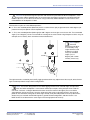
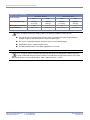
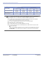
CAUTION: Always use two red button pins (3/8" x 1.5") to secure each grid link to the MG-MICA. Avoid
using the blue button pins (3/8" x 1.125") since they are shorter and will not lock in place.
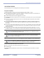
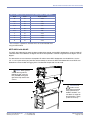
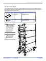
Follow the labeling on the grid to orient the loudspeakers; a large arrow on each side is labeled Front. Attach the top
MICA enclosure to the grid links with one 3/8" x 1.125" quick-release pin (with blue release button; part #134.021)
per link.
SAFETY WARNINGS!
1. Always use two quick release pins on each MG-MICA link.
2. DO NOT use ground-stack holes for flying points.
MICA / 600-HP
REAR LINK
Ground-Stacked
Position
Stowed
Position
MG-MICA REAR LINK
Maximum Uptilt
MICA / 600-HP
FRONT LINK
Ground-Stacked
Position
FRONT
MG-MICA REAR LINK
Maximum Downtilt
Stowed
Position
MG-MICA FRONT LINK
Maximum Uptilt
MG-MICA
MG-MICA FRONT LINK
Maximum Downtilt
Link Positions for Maximum Downtilt
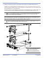
CAUTION: The
front and rear
grid links are of different
widths, and should not be
substituted for each other.
The rear link is wider than
the front.
CAUTION: The
leveling feet must
always be detached from
the MG-MICA grid before
flying a system. Unscrew
the entire assembly,
including the threaded leg,
and remove completely.
Meyer Sound Laboratories Inc.
www.meyersound.com
T: +1 510 486.1166
F: +1 510 486.8356
PN: 05.147.034.01 A
Page 11 of 44