1
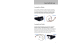
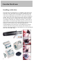
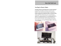
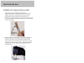
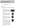
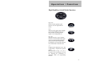
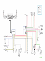
Contents
Introduction
Page 2
Installation
Page 3
Instrumentation
Page 7
Operation / Function
Page 9
Programming
Page 18
Appendix
Page 21
Wire Diagram
Page 22
Warranty
Page 24
All Rights Reserved. Reproduction by any means, electronic or mechanical
including photocopying, recording or by any information storage and retrieval
system or translation in whole or in part is not permitted without written
authorization from Signal Dynamics Corporation.
Copyright © Signal Dynamics Corporation.
1
Introduction
LINX™ Network Bus Electrical System
System Overview:
Simpler, easier installation and comprehensive rider information; these
are the some of the basic advantages of the LINX™ Network Bus
Wiring System. As you read this manual you will realize the significant
improvements and advanced features that this system provides over
conventional wiring harnesses. Additionally, updates, knowledge base
and Q&A for this system will be updated and posted on the LINX™
web-site as they occur at www.SignalDynamics.com/LINX.
How does LINX™ work?
LINX™ is a serial data communication network for connecting the
various electrical functions of the motorcycle over a single network
cable, eliminating complex electrical wiring, confusion and errors while
wiring or troubleshooting the electrical system.
LINX™ System
The LINX™ system is composed of: three communication modules, two
handle bar switches, and two wiring harnesses. These modules when
connected with the network cables, communicate with each other,
transfer information and self-check themselves for proper operation. If a
problem does develop, a written text message is displayed on the Liquid
Crystal Display (LCD) module. The system is designed to be simple, yet
provide more practical and useful information to the user.
2
Installation
Locating Rear Module
The rear module is identified by its’ Black Connector, and should be
located in an area that is close to the battery and Starter Solenoid, and
also central to all of the devices it connects to. The module is splash
proof, but should be mounted in an area that has some protection from
water and heat. Under the seat on the battery box is usually a good
location. The module mounts with the enclosed double sided tape.
Locating Front Module
The front module is identified by it’s Grey Connector, and should be
located in an area that is central to all of the devices it connects to.
Under the gas tank, or in the headlight housing are two common
locations. The module is splash proof, but should be mounted in an area
that has some protection from water and heat. Once the two modules are
mounted the 4 wires that connect them should be connected. A 4 pin
connector is included, but these wires can be cut or extended as needed.
The module mounts with the enclosed double sided tape.
3
Installation
Installing switch cubes
The switch cubes are designed to fit a 1” handlebar, and connect to the
front brake switch, and clutch switch (optional). Installing the switch
cubes involves drilling a hole in the handlebar where the switch cube
will be located, and another where the wires will connect to the display
module. These wires come with the ends already crimped on, but they
can be cut off and easily re-crimped in the event you need to fish the
wire through a small hole (see crimping instructions). After the hole is
drilled and the wire fished through, simply plug the connector into the
switch, and connect the two wires on the right side to the brake switch,
and the two wires on the left side to the clutch (optional). It is
recommended that an electrical grease (not included) be used on the
connector and socket to help prevent corrosion from moisture. Last
insert the switch into the housing, and install the four screws through the
back side of the saddle clamp.
4
Installation
Installing the Display Module
The display module can be mounted either above or below the handlebar
by attaching the backing plate mounting tab to a handlebar clamp (not
included). The wires from the switch cubes will come out of the
handlebars, into the display housing, and plug into the appropriate
connector. The data wire from the front module is routed to the display
module and plugged into the appropriate connector. The data wire comes
with the end already crimped on, but it can be cut off and easily recrimped in the event you need to fish the wire through a small hole, or
shorten it (see crimping instructions). It is recommended that electrical
grease (not included) be used on the data cable and socket to help
prevent corrosion from moisture. Be sure to plug the cables into the
correct sockets as the unit can be damaged from improper installation.
They are labeled “L” & “R” (for Left & Right handlebar switches) and
“C” for Front Module.
5
Installation
To Replace the Connector End on a Cable.
1.
2.
3.
6
Strip about 1” of the outer insulation with an RJ-45
stripper/crimping tool, the inner insulation does not need to be
stripped. These tools are commonly used to crimp computer
network cables, and are avalible at most electronic stores.
Insert the wires into the low profile connector. Be sure the blue wire
is to your left with the clip of the connector away from you, and the
connector pointing up.
Insert the connector into the crimper, and crimp. Be careful no to
push the connector too far into the crimper as the low profile
connectors do not have a stop to position the connector at the
correct position. Also be sure the wires are all of the way into the
connector when you make the crimp. It is a good idea to crimp the
connector twice to be sure that all of the conductor pins have
pierced the wires.
Instrumentation
Display Module:
When the system is powered-on, a self-test will run and if any faults are
noted, they will be displayed. After this, the logo will be displayed for 3
seconds, and then the module will enter the operational mode. The
following items will be displayed on the screen in the operational mode:
Information & Icons on LCD Screens:
•
•
•
•
•
•
•
Speed (in MPH or KPH).
Engine RPM (digital readout and bar graph).
Clock.
High Beam “ON” Icon.
Bike in “Neutral” Icon.
Information Window (one of the following)
• Turn Signal Left / Right
• Hazard Flasher On.
• Run / Kill Status.
Text information window: (toggles between the following with the
# key on the right handlebar switch).
• Odometer
• Trip 1 (Reset by pressing the # key for 3 seconds)
• Trip 2 (Reset by pressing the # key for 3 seconds)
7
Instrumentation
•
•
Temperature and Voltage.
System Alert text message. (If Present)
Indicators:
The indicator icons are located to the left and right sides of the LCD
display screen. When they are active they are back-lit with LED lighting.
8
•
Turns Signal Direction Arrows – Located
at the top and to the left and right of the
LCD display screen. These indicators are
backlit with green LED’s and will flash
when the turns signals or hazards flashers
are activated.
•
High Beam Headlight Indicator –
Located below the left turns signal arrow.
This indicator is backlit with a blue LED
to indicate when the high beam has been
selected.
•
Neutral Indicator – Located below the
right turn signal arrow. This indicator is
backlit with a green LED to indicate when
the transmission’s neutral switch circuit is
completed.
•
Alert Condition Indicator – Located at
the bottom of the indicators on both sides
of the LCD display screen. When an
“event” or “fault” condition occurs, these
backlit indicators will alternately flash for
ten seconds then remain steady until the
condition has been cleared. A text
message of the Alert Condition can be
read in the odometer area of the display.
The fault will also be logged in the
systems error log.
Operation / Function
Front (Tank) Module
The following outputs and operations are controlled by the Front
Module:
•
•
•
•
•
•
Ignition
Compression Release
NOS solenoid (optional)
Left & Right Front Turns Signals
Headlight High & Low beam
Horn
Rear Module
The following inputs/outputs and operations are controlled by the Rear
Module:
•
•
•
•
•
•
•
•
•
Speedometer Input (Transmission)
Tachometer Input (Cam / Crank Sensor or Ignition Coil)
Neutral
Oil Pressure
Rear Brake Input
Rear Brake Light
Right & Left Rear Turn Signals
Starter Solenoid
Horn
(This is an optional secondary circuit for those who
prefer the horn to be mounted near the rear of the bike.
9
Operation / Function
Switches:
The handlebar switches are designed for easy installation or removal
with plug-in connector. They are also LED back-lit for easier button
identification during night time conditions. They provide a positive
tactile click when depressed.
Left Handlebar Switch Module Functions
Left Turn
Starts or cancels left turn signal
function. (See turn signal function
below)
High / Low
Toggles the headlight from high to low
beam. Low beam is automatically
selected when the key is turned “On”.
“Up” key in menu mode.
Horn
Activates the Horn circuit.
“Down” key in menu mode
(*)
Used for programming, in the program
mode. (Optional – can be used to
activate NOS system if installed.)
“Select” key in menu mode.
10
Operation / Function
Right Handlebar Switch Module Functions
Right Turn
Starts or cancels right turn signal
function. (See turn signal function
below)
Start
Will activate the engine starter solenoid
circuit if: the Run/Kill switch is set to
Run, the bike is in neutral, and the
engine is not running (RPM =0).
Run / Kill
Will allow the bike to start if the Run
function is selected. Will kill the engine
or prevent a start if the Kill function is
selected. An X will be visible on the
LCD display screen if the kill switch has
been selected and is in the kill mode.
(#)
Toggles between Odometer, Trip 1, Trip
2, and Voltage / Temperature if pressed
quickly.
Press and hold on trip 1 or 2, for 3
seconds to reset trip mileage to 0. Used
for calibrating the speedometer in
calibration mode (see programming
section).
11
Operation / Function
Initial LINX™ Power-UP & Starting
Key Switch Operation:
When the key switch is turned on, power is applied to the LINX™
system and a self-test will run. If any faults are noted, they will be
displayed on the LCD screen. After this, a Logo and VIN # (if
programmed) will be displayed for 3 seconds, and then the LINX™
system will enter the operational mode. The following items will be
displayed on the screen in the operational mode:
• Digital Speedometer
• Digital & Bar-graph Tachometer
• Digital Odometer
• Time
• Information Window
• Neutral (if transmission is in neutral)
Auto Battery Conservation:
To conserve battery energy, when the key if first turned on, the headlight
will automatically be selected to low beam. Additionally, the LINX™
system will turn the headlight off during starter engagement. Once the
start button is released, the headlight will turn back on.
System Auto Shut Down:
If the key is turned on for 10 minutes, and the engine is not started, the
LINX™ system to include the headlight will turn off to avoid battery
drain; however, the marker lights will remain lit if the bike is wired with
marker lights. To reinitialize the system and start the bike, the key will
have to be turned off, and then back on.
Starting:
To start the motor while stopped: the transmission must be in neutral
and the Run/Kill switch must be in the “Run” Mode If an “X” is
displayed in the information window the bike is in the kill mode, if
nothing is displayed it is in the run mode. To complete the start, press
12
Operation / Function
the start button on the right handlebar switch to initiate the engine
starter. The starter motor can not be accidentally engaged if the LINX™
system recognizes that the motor is already running. If a start is
necessary while the bike is rolling, a start with the electrical starter
motor can be accomplished above 5 MPH, by assuring the Run/Kill
switch is in the “Run” position and the clutch is pulled in. To complete
the start, press the start button.
Starter Motor Safety Shut Down:
To prevent the starter motor from being damaged from overheating, the
LINX™ system will only allow for a total of 10 seconds of cranking
time in any one-minute period. If this cranking time is exceeded, the
LINX™ system will automatically shut down the starter circuit and not
allow any further starts for the remainder of one minute or until the key
switch is turned off, and then back on. Normally, an engine should easily
start within this time period. If it does not, it should be checked to
determine the cause and then corrected.
Compression Release:
When the start button is pressed, the compression release circuit is
activated providing power to the compression release solenoid.
(Optional on some bikes)
Nitrous Oxide System (N.O.S.):
If your bike has a Nitrous Oxide System, the star (*) button on the left
handlebar switch cube controls its operation. With the motor running
and RPM increasing above 1000 RPM the NOS circuit is enabled to
providing power to the Nitrous Oxide solenoids.
Note: When using NOS, be sure to follow the NOS manufacturers
recommended procedures. Failure to comply can cause engine damage
and bodily harm.
13
Operation / Function
Information & Alert Conditions
Text information window:
The Text information window is located at the bottom of the LCD
screen. To toggles between the following items, press the (#) key on the
right handlebar switch.
•
•
•
•
•
Odometer
Trip 1 (Reset by pressing the # key for 3 seconds)
Trip 2 (Reset by pressing the # key for 3 seconds)
Temperature and Voltage.
System Alert text message.
Alert Text By-Pass:
If an alert condition exists (an event or fault) it will be displayed in the
LCD information window and LED warning alert indicator icons will
illuminate. If the rider would like to bypass the warning message he can
toggle back to his previous setting by momentarily pressing the “pound
(#)” button on the right handle bar switch.
Event or Fault Clearing:
If the LINX™ system detects an abnormal condition, a message will be
displayed on the LCD screen and the Alert Icons will illuminate. The
message and alert icons will remain until the fault is cleared. If the
condition requires a repair, such as a bulb replacement or a short, once
the repair has been made and the key switch has been cycled off then on,
the alert message will be cleared from the LCD screen.
14
Operation / Function
Lighting
Marker Lights:
Turn Signal Lights also function as marker lights.
This function enables single intensity incandescent or LED bulbs to have
a marker light feature.
Headlight Features & Operation:
Low Beam
When the key switch is first turned on, the headlight is
automatically selected to low beam to conserve battery
power. When an engine start is initiated, the headlight
is automatically cycled to “off “. However, the turn
signal/marker lamps remain “on”. This feature
conserves battery power during the start, but provides
marker lights for conspicuity. The system
automatically switches to high beam in the event of a
low beam failure.
High Beam
When “High” beam is selected on the handlebar
switch, power is supplied to the high beam. When in
high beam, the LCD display screen shows a high beam
icon as well as a blue LED indicator light is
illuminated to the right side of the display screen. The
system automatically switches to low beam in the
event of a high beam failure.
15
Operation / Function
Turn Signal Function:
The turn signal selection buttons are located on the left and right handle
bar switch cubes. The turn signals are activated by pressing the
appropriate button. The turn signals will flash for 7 seconds then
automatically cancel. The number of flashes or seconds remaining will
be displayed in the information window of the LCD Screen. If more
flash time is required simply press and hold the turn signal button, and
the number of seconds or flashes increases. The signal can be cancelled
manually by pressing the same button again. If the brakes are applied
while the turn signal is flashing they will continue to flash until the
brakes are released plus 10 seconds.
Additional Features:
•
•
•
16
Turn Signal Count Down: With self-canceling turn
signals, it is a definite advantage to be able to know
when the self-canceling feature will stop flashing the
turn signal. This feature shows you the remaining
flashes on the LCD display screen. When the turn
signal has been activated, it will alternately flash an
arrow and then remaining time (seconds) of flashes.
Turn Signal Hold: If the brakes are applied after a
turn signal has been selected, the flashers will continue
to flash as long as the brakes are applied plus 10
seconds. This feature is beneficial when stopped at a
signal light, it will keep the turn signal engaged until
the brake is released, and it will then flash an
additional 10 seconds.
Hazard Flashers: When selected will flash until
cancelled and a hazard icon will be shown on the LCD
display screen. To engage, depress both the left and
right turn signal buttons for 1 second. To cancel,
depress both buttons again for one second.
Operation / Function
•
Brake Lights: When the brakes are applied and the
motorcycle is stopped, the brakes remain on until the
bike accelerates. This will also cause the turn signals
to continue to flash 10 seconds after the bike
accelerates.
Circuit Protection
The LINX™ system does not require external fuses for circuit
protection. The sophistication of this system automatically checks each
circuit thousands of times per second to assure it is operating properly. If
it detects an anomaly, it will shut down the faulty circuit before damage
can occur and it will send an alert message to the LCD display screen.
Once the fault is corrected and the key switch has been cycled “off” then
“on”, the system checks itself again and if no fault is present, normal
operation resumes.
17
Programming
Program Mode:
To enter the program mode, the bike’s run/kill switch must be in “kill”
position. After selecting “kill”, the press ( * ) and ( # ) together for 5
seconds. The program menu will then pop-up on the LCD screen.
The following keys are used to program the module:
Key
Function
High / Low
-Scroll Up
Horn
-Scroll Down
(*)
-Select
Programmable Items:
•
Screen Contrast – To adjust the contrast of the display.
•
Time – This is the time displayed on the screen in the Operating
Mode and is used for error logging.
•
Date – This is the date used for error logging.
•
Metric or SAE – toggles the display from MPH/KPH,
Fahrenheit/Celsius on the thermometer and from Miles/Kilometers
on the odometer and trips display.
•
Calibrate Temperature – Use this setting to calibrate your bikes
temperature to a known thermometer.
•
Tach Multiplier – Used to set the number of pulses sent per engine
revolution.
•
Max RPM - Set or View Max RPM (Max RPM may only be set
once on some bikes).
18
Programming
•
Vehicle Identification Number - Set or View VIN# (Vin # may
only be set once on some bikes).
•
View Logs - This will display a history of “events” and “faults”
encountered by the system. This log erases the oldest message when
the amount of space for storage is maxed out. Faults are not
erasable, but events are.
The format for the error log is: Time / Date of Condition Condition Text Message
•
Clear Event Log - Used to clear event logs. Note: error logs
cannot be erased.
•
User Options:
Brake to Start – Must apply brakes to start bike (default off)
Lights Off with Kill – Turns off lights when bike is turned off with
a 5 second time delay (default off)“timedelay”.
•
Module Info – Shows software revisions of all modules on the
network.
•
Exit Program mode: Selecting this will exit configuration screen
and enter operating mode. (Bike will return to operating mode after
30 seconds of inactivity)
Measured Mile Mode:
This mode is used to calibrate the speedometer for your bikes particular
final drive/ wheel-tire configuration.
• To calibrate the speedometer, select a location that has one mile
measured with a beginning and ending point (mile markers on
an interstate are a good place to do this).
• To enter this mode press the # button for 5 seconds while in
operating mode with the odometer displayed. (The system will
not enter the measured mile mode if Trip1, Trip2, or
19
Programming
•
Voltage/Temperature are displayed) This will take you to a
screen prompting you to press the # button at the beginning of a
measured mile. When you pass the beginning mile marker press
the # button. The screen will then prompt you to press the #
button at the end of the ending mile marker. When you do this,
the speedometer will be calibrated and return to the operating
mode. (It does not matter at what speed this is done, or if the
bike accelerates or decelerates during the measured mile)
After calibration is complete, verify the accuracy by checking
the accuracy of the odometer over a 5 measured mile course. It
is important that verification of the speed is made. If your
measured mile was not exactly one mile the speed readout may
be incorrect. Also, any time a change is made to the diameter of
the wheels, drive sprockets, or tires, this may affect the
accuracy of the speedometer and recalibration may be
necessary.
Memory:
The LINX™ Network Bus electrical system has 3 independent modules,
which each record and keeps a copy of your stored settings and
information. In the event of a module failure, simply turn the key “Off”,
replace the defective module, and then turn the key “On”. When the
power is restored by turning the key “On”, the new module will be
programmed with your stored settings from the other two modules.
(Modules must be replaced one at a time, and powered up between
changes in order to synchronize settings) These stored settings include:
• VIN#
• Odometer and Trip Values
• Error Log
• Software revision #
• Number of pulses that equal 1 mile
• Max RPM
• Vendor configuration (Logo and vendor specific settings)
• Screen Contrast
• Metric or SAE
20
Appendix
System Specification:
System Power
12VDC 30Amps
Operating Temperatures
32°F to 122°F (0°C to 50°C)
Physical Size
Front / Rear Module 2.0” X 3.0” x 1.5”
Display Module 2.0” X 3.5” X 1”
Maximum Amperage Load:
Headlight
High Beam
Low Beam
Turn Sign/Marker Light
Brake/Running Light
Horn
Starter Solenoid
NOS Solenoid
Compression Release
Ignition Coil
10A
10A
5A each
5A
5A
100A Momentary (50A
Continous)
5A
5A
5A
Note:
The LINX™ system draws a very small amount of current in the “Off”
mode. It is recommended that the battery be maintained with a charger if
the bike is not ridden regularly. A properly maintained battery adds life
and dependability to your battery.
21
Warranty
One Year Limited Warranty
Signal Dynamics Corporation warranties this product at time of purchase
to be free from defects in materials or workmanship to the original
purchaser.
Signal Dynamics Corporation's obligation under this warranty is limited
to repairing or exchanging the unit if the unit is returned, postage
prepaid, to Signal Dynamics Corporation within one (1) year from date
of purchase.
The warranty is void if the unit has been incorrectly installed, damaged,
or tampered with. The foregoing warranty is exclusive and is given and
accepted in lieu of any and all other warranties, expressed or implied,
including without limitation, the implied warranties of merchantability
and fitness for a particular purpose.
This warranty specifically limits Signal Dynamics Corporation's liability
to unit replacement only and specifically excludes any consequential
damage arising from use, proper or improper, or failure to properly
function.
A copy of your purchase receipt or other proof of purchase is required
when applying for warranty consideration.
01-22-2007
24