1
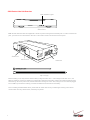
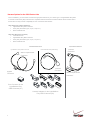
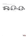
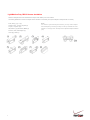
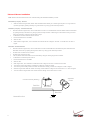
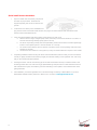
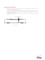
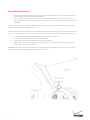
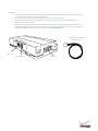
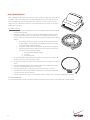
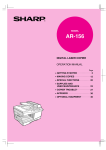
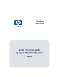
Installation Guide
Verizon Networkfleet
5000 PRODUCT LINE
INSTALLATION GUIDE
5500 Diagnostic Hardware (Light/Medium/Heavy Duty) | 5200
Non-Diagnostic Hardware (Universal)
1
Table of Contents
Getting Started
Registration Form ........................................................................................................................... 3
5000 Product Line
Unit Overview .................................................................................................................................. 4
Harness Options ............................................................................................................................. 5
Light/Medium Duty OBD-II Harness Installation ........................................................................... 7
Heavy Duty Harness Installation.................................................................................................. 10
Universal Harness Installation ..................................................................................................... 11
Quick Install Harness Installation ................................................................................................ 12
Verifying Successful Installation ................................................................................................. 13
Creating Tamper Evidence ........................................................................................................... 14
Completing Installation ................................................................................................................ 15
Securing the Device ...................................................................................................................... 16
OPTIONAL Accessory Installation Instructions
Window-Mount GPS Antenna....................................................................................................... 17
Sensor ............................................................................................................................................ 18
Garmin® .......................................................................................................................................... 20
Bluetooth Extension Module….…………………………………………………………………………21
Port Expansion Module (PEM) ..................................................................................................... 22
Quake Satellite Modem ................................................................................................................. 23
Verifying Successful Installation/LED Behavior......................................................................... 24
Pelican Micro Case ....................................................................................................................... 25
Appendix
Troubleshooting Light Indicators ................................................................................................ 26
Frequently Asked Questions........................................................................................................ 27
Contacting Networkfleet ............................................................................................................... 28
2
Registration Form
Fill out the enclosed registration form before completing installation.
Record the following information:
Vehicle Identification Number (VIN) | License Plate | Year | Make | Model
Unit’s Serial number (10 digits)
Installation Tip:
Metal walls and tall buildings may
interfere with the reception from
GPS satellites and the cellular
network. Perform installation when
the vehicle is in clear view of the
sky. Conduct final installation
verification after the vehicle has
been running outside for 15
minutes.
3
5000 Product Line Unit Overview
LED Indicator Lights
Side of Unit
Note: All 5500 and 5200 units are shipped with a knock-out panel covering the sensor/serial ports. In order to access those
ports, you must use an X-ACTO knife to slice off 2 of the 3 tabs in order to remove the knock-out panel.
Serial Port
Sensor Port
Data Port
Zip Ties (x4)
Before installing a unit, verify that the vehicle’s battery voltage is at least 12.5 V. If the voltage is lower than 12.5 V, the
battery’s health may need to be verified by a professional to determine if the battery needs to be replaced. While the 5000
series units go into a low power mode, the units still draw an average of 16 mA. Also, having two or more devices plugged
into the OBD-II port and/or the auxiliary port results in additional current draw from the battery.
Prior to installing the Networkfleet device, please start the vehicle and note any indicator lights showing on the vehicle
console which show any vehicle issues, should they be present.
4
Harness Options for the 5000 Product Line
Prior to installation, you must select and order the appropriate harness for your vehicle type. The Light/Medium Duty OBDII Harness and the Heavy Duty Harnesses are compatible with both the 5500 and 5200 hardware devices. Please refer to
the list below to verify harness compatibility for each of the 5000 series devices:
5500 (Diagnostic Capable Hardware)
•
Light/Medium Duty OBD-II Harness
•
Heavy Duty Harnesses (6-pin, 9-pin, or 9-pin “D”)
•
Quick Install Harness
5200 (Non-Diagnostic Hardware)
•
Universal Harness
•
Light/Medium Duty OBD-II Harness
•
Heavy Duty Harnesses (6-pin, 9-pin, or 9-pin “D”)
•
Quick Install Harness
Embedded Solutions
Light/Medium Duty OBD-II Harness
Quick Install Harness
Universal Harness (5200 Only)
OBD-II Replacement
Connector
Bypass
Connector
Harness
Connector
OBD-II Replacement
Connector
Core Connector for the
Light/Medium Duty
OBD-II Harness (X1)
Harness Adapters for the Light/Medium
Duty OBD-II Harness (X8)
5
Harness
Connector
Heavy Duty Harnesses
There are 3 different harness options for Heavy Duty vehicle installations:
6-pin Harness, 9-pin Harness, and 9-pin “D” Harness.
6-pin Harness
6
9-pin “D” Harness
9-pin Harness
Light/Medium Duty OBD-II Harness Installation
Select an Adapter that most resembles the shape of the OBD-II port of the vehicle.
Use these guidelines to match an adapter to the vehicle it is most likely to fit (each adapter is stamped with a number).
Ford, GM (1), (6), or (8)
Honda, Lexus, Toyota, Chrysler (2)
Toyota*, Chrysler* (2a)
GM, Saturn (3) | Mercedes, BMW (4)
Porsche, Audi, Volkswagen (5)
Volvo (6) | Saab (7)
7
Note:
For certain Toyota and Chrysler vehicles, you may need to adjust
the #2 adapter by removing the clips on the top and bottom of the
adapter. To the right is an example of the adjusted adapter labeled
(2a).
Light/Medium Duty OBD-II Harness Installation
Core Connector Assembly
1. Snap the selected plastic adapter to the back of the Core Connector.
2. Attach the Core Connector to the OBD-II Replacement Connector.
Data Port Connection
Connect the Harness Connector to the Data Port.
OBD-II
Replacement
Connector
Adapter
Bypass
Connector
Core
Connector
Data Port
Networkfleet
Unit
8
Harness
Connector
Light/Medium Duty OBD-II Harness Installation
Connecting to the OBD-II Port
1.
With the vehicle’s engine OFF, remove the vehicle’s OBD-II
port. The OBD-II Connector may be hidden behind a hush
panel.
a. To remove the connector, you may need to
remove screws or depress the clips.
2.
Connect the Bypass Connector to the vehicle’s OBD-II port
that was previously removed.
3.
Attach the Core Connector to the position where the original
OBD-II connector was installed. Secure it with the screws or
clips removed from the OBD-II Connector’s original position
(if applicable).
To Vehicle
Original OBD-II Port
Bypass Connector
Networkfleet Unit
Core Connector
•
•
9
5500 Series units installed with a light duty harness cannot be installed along with lift gates that are plugged into
the OBD port. Refer to the TIB: Lift Gates and Unit Interference.
If other devices besides the 5500 series unit need to be plugged into the OBD port, please refer to the TIB: Scan
Tool Detection and Aftermarket Devices.
Heavy Duty Harness Installation
Connecting to the Diagnostic Link Connector (DLC) Port
1. With the vehicle’s engine OFF, unscrew the DLC port from its position under
the dashboard*. In most cases, the DLC port is located under the dashboard
on the left side of the steering wheel, facing toward the floorboard.
2.
Plug the Bypass Connector of the harness into the DLC port that was
previously removed from the vehicle in step 1. For the 9-pin connector, turn
the rotating cap clockwise to lock into place.
3.
Mount the Core Connector of the harness into the place in which the DLC
port originally resided.
*Note: DLC Port Connector may also be located near or
behind the driver seat.
To Vehicle
Original DLC Port
Networkfleet Unit
Bypass Connector
Core Connector
Dashboard
10
Universal Harness Installation
Note: Please ensure that the Driver Door is OPEN during the ENTIRE installation process.
Black Wire (one pair) - Ground
•
With the vehicle’s engine OFF, attach both the Black Wires directly to a chassis ground point or to a ground line
(chassis ground) by splicing directly to a ground lead or by using a poke and wrap method.
Red Wire (one pair) - Continuous Power
•
With the vehicle’s engine OFF, use the voltmeter to locate a 12-volt BATTERY lead and attach both the Red Wires
by splicing directly to the lead or by using a poke and wrap method. If attaching to a fused lead or using an in line
fuse (not necessary), verify that it is at least 5 amps.
•
To determine a true Continuous Power source:
1. Ensure the Driver Door is OPEN
2. Select a wire
3. With vehicle’s engine OFF, use a voltmeter to measure the DC voltage on the wire. It should show 12 VDC or
higher.
Blue Wire - Switched Power
•
With the vehicle’s engine OFF, use the voltmeter to locate an IGNITION line with switched power and attach the
Blue Wire to the line by splicing directly to the lead or by using a poke and wrap method.
•
Do NOT use an inline fuse on this line.
•
Do NOT use accessory Power.
•
The red, black and/or blue wires can be extended by using the same gauge wire if needed.
•
To determine a switched power source:
1. Ensure the Driver Door is OPEN.
2. Select a wire.
3. With engine OFF, use voltmeter to measure the DC voltage on the wire. It should show 0 VDC.
4. Turn the key to the ON position. Confirm the voltage is 10 Volts or higher.
5. Turn the key to the RUN position and while the vehicle is starting, confirm the voltage is 9 Volts or higher.
6. Start the engine and while the vehicle is running confirm that the voltage on the same wire is 13.1 VDC or higher.
7. Turn the vehicle’s engine OFF and confirm that the voltage on the same wire is 0 VDC.
Switched
Power
Constant Power (Battery)
Red Wire
Black Wire
Blue Wire
Networkfleet Unit
11
Ground
Quick Install Harness Installation
12
1.
Open box. Make sure all necessary components
are inside for proper install. Harnesses are
shipped separately and cannot be returned once
opened.
2.
Locate the DLC or OBD-II port for installation and
plug-in the DLC side of the Quick Install Harness, then plug-in the vehicle harness side of the Quick Install
Harness into the Networkfleet device.
3.
Verify successful installation with LED Indicator Lights sequence on side of unit.
a. Start the vehicle’s engine. All lights (Red, Yellow, and Green) on the device should turn on solid for 15
seconds and then begin blinking rapidly (twice a second).
b. The device is operating normally when the rapid blinking ceases and the Green and Yellow lights begin
to blink in a slow pattern (ON for 5 seconds and OFF for 1 second).
c. The vehicle must be idled or driven for at least 15 minutes to reach normal operating mode and ensure
activation is complete.
d. Call Customer Care at 866.227.7323 (option 5) to verify successful install and to acquire a case number.
4.
Completing Installation: Before securing the device under the dashboard, make sure that you have recorded the
full VIN (17 digits), hardware serial number (10 digits) and odometer reading on the registration form. Also verify
that you have checked the light indicators.
5.
Securing the Device: Use the enclosed long zip ties to fasten the hardware securely to a stable bracket or wire
bundle high under dash. Unit must be facing up (Networkfleet logo side) and with no metal obstructions above it
that would block the signal; check that the green LED is blinking in a slow pattern, which verifies that the unit is
getting GPS data.
6.
After installation, provide the registration form to the fleet manager for delivery to Networkfleet or if you are a
Networkfleet Certified Installer, please fax to 866.616.2131 or email to [email protected]
Verifying Successful Installation
1.
2.
3.
Start the vehicle’s engine. All lights (Red, Yellow, and Green) on the device should turn on solid for 15 seconds
and then begin blinking rapidly (twice a second).
The device is operating normally when the rapid blinking ceases and the Green and Yellow lights begin to blink in
a slow pattern (ON for 5 seconds and OFF for 1 second). The Red light pattern will continue to vary and should
not be used to verify installation.
The vehicle must be idled or driven for at least 15 minutes to reach normal operating mode and ensure activation
is complete.
LED Indicator Lights
Side of Unit
13
Creating Tamper Evidence
Once the vehicle harness is plugged in, slide the Networkfleet branded yellow
zip ties through the two slots provided on the harness connector. Once the zip
ties are in place, tighten and remove the excess plastic. If possible, position the
zip ties so that the “DO NOT REMOVE” message is showing.
14
Completing Installation
Before securing the device under the dashboard, make sure that
you have recorded the VIN, hardware serial number and odometer
reading on the registration form. Also verify that you have checked
the light indicators. After installation, provide the registration form
to the fleet manager for delivery to Networkfleet or if you are a
Networkfleet Certified Installer, please fax to 866.616.2131 or
email to [email protected].
15
Securing the Device
Use zip ties to fasten the hardware securely to a stable bracket
or wire bundle under the dash.
IMPORTANT: The device must be installed high in the dashboard area and secured with
the top of the unit facing the sky (the side of the unit with the Networkfleet logo). Also
verify that the device is not covered by metal and check that the green LED is blinking in
a slow pattern, which verifies that the unit is getting GPS data (as
explained on page 13).
To avoid damage from condensation, ensure that the unit is not at the lowest point of the
installation and secure it away from moving parts.
16
Window-Mount GPS Antenna
1.
2.
Units are shipped with a knock-out panel covering the sensor/serial ports. First, use an X-ACTO knife to slice off
2 of the 3 tabs in order to remove the knock-out panel.
Use enclosed alcohol preparation pad to clean the inside windshield where the antenna is to be placed. For
proper operation, the antenna should be placed on flat, clear glass on the driver’s side interior lower corner of the
windshield.
Ensure that the antenna does not extend more than 4 ½ inches from the bottom of the interior windshield and is located
outside the area swept by the windshield wipers.
Do NOT place the antenna in the following areas - Behind stickers or decals already on the glass, on the shade band of the
glass, on a curved area of the glass, on a moist or damp area of the glass, or on an area that will obstruct the driver’s view
3.
4.
5.
6.
Connect the window-mount GPS antenna to the serial port on the side of the unit.
Run the cables up the door seam or up through the dashboard.
Remove the protective strip from the antenna to expose the adhesive.
Carefully affix the antenna to the glass that was prepped in Step 2. Press the antenna firmly to the glass while
being careful not to damage the antenna.
Installation Tip: Please note that the ideal temperature range to perform the installation is between 70°F to 100°F (21°C to
38°C) with a minimum suggested application temperature of 60°F (15°C).
17
Sensor
The 5500 and 5200 devices include a sensor port for monitoring various voltage events occurring within the vehicle such
as: PTO engagement/disengagement, secondary engine on/off, and door open/close.
Please review prior to performing sensor installation:
•
Installer shall use only a digital multi-meter to verify that line Voltage is within the product tolerances.
•
Installer shall use 24 gauge (minimum) wires for installation.
•
Electrical connectors must be used when attaching sensor wires.
•
Voltage testing should always be performed with a vehicle door open to avoid retained accessory power issues.
The 5500/5200 comes equipped with two sensor inputs. Each sensor will be associated with a pair of input wires. One pair
of wires (Purple, Black) will be associated with Sensor 1 and the other pair of wires (Blue, Black) will be associated with
Sensor 2.
Use the Black wire of each pair to make a secure vehicle ground connection. Then, connect the other wire (Blue or Purple)
of each pair to the desired signal to be monitored.
If only one wire pair (sensor input) is to be used, the other pair must be twisted together and insulated via heat shrink or
some other secure means to prevent contact with any vehicle structures and to ensure it does not interfere with any moving
parts in the vehicle.
The sensor wires can be extended with the same gauge wire if needed.
The signal to be monitored should have two voltage states: One where there is no voltage
(i.e. zero volts when referenced to ground) and another that falls in the range +5 to +24 or -5 to -24 volts. The signal being
monitored should be capable of supplying 3 mA when a voltage is present. It is important that the voltage signal be tested
to ensure it is continuously providing the necessary voltage and current when in the “on” or “active” position.
The following table shows how the signals are interpreted.
Wire A (Black)
Ground or reference for wire B
Wire B (Blue or Purple)
Off (-3V < x < +3V)
On (-24V < x < -5V or +5V < x < +24V)
Undefined (-5V < x < -3V or +3V < x < +5V)
On a system where the PTO and the Sensor use the same battery:
•
Connect the Black Sensor Wire to Battery, which will be the reference.
•
Connect the Purple or Blue Wire to the PTO switch.
On a system where the PTO and the Sensor use different batteries:
•
Connect the Black Sensor Wire to Battery, which will be the reference.
•
Connect the Purple or Blue Wire to the PTO switch.
18
To Install
1. Units are shipped with a knock-out panel covering the sensor/serial ports. First, use an X-ACTO knife to slice off
2 of the 3 tabs in order to remove the knock-out panel.
2. Connect the Sensor Input Harness to the Sensor Port on the 5500 or 5200 device.
3. Verify installation by checking the LED behavior of the device (see page 23) and call Customer Care at
866.227.7323 and select Option 5.
4. Before securing the device under the dashboard, make sure you have recorded the appropriate information on
the Sensor Installation Card included with the Sensor Input Harness. Once all information is recorded, follow the
instructions detailed on the card to update your fleet on www.networkfleet.com.
Sensor Input Harness
(Blue & Purple)
Serial Port
Sensor Port
19
Data Port
Garmin®
Networkfleet is ONLY compatible with Garmin devices that support Fleet Management Interface Version 2.6 and higher.
The list of compatible units can be found here: www.garmin.com/solutions/pnd/supportedproducts.jsp (look for
“Supports Version 2.6 Fleet Management Interface” in the description).
All Garmin devices, even if they support Fleet Management Interface Version 2.6, will need a firmware update prior to
installation. Please contact your sales representative or Networkfleet Customer Care to obtain update instructions.
To Install
1. Units are shipped with a knock-out panel covering the sensor/serial ports. First, use an X-ACTO knife to slice off
2 of the 3 tabs in order to remove the knock-out panel.
2. Connect the modified Garmin FMI Cable to the Serial Port on the 5500 or 5200 device.
3. Plug the other end of the modified Garmin FMI cable into the Garmin device.
4. Required: To verify installation and to enable Garmin functionality, call Customer Care at 866.227.7323 and
select Option 5.
5. Before securing the device under the dashboard, make sure you have recorded the appropriate information on
the Garmin Installation Card included with the modified Garmin FMI Cable. Once all information is recorded,
follow the instructions detailed on the card to update your fleet on www.networkfleet.com.
20
Bluetooth Expansion Module
The Bluetooth Expansion Module (BTE) provides Bluetooth connectivity between 5500 devices and the J. J. KellerTM
compliance solution. The pigtail on the BTE can be connected to either a modified Garmin FMI cable or a window mount
GPS antenna.
Important: If BTE is used, the modified Garmin FMI cable should only be connected to one device (BTE). Leave the other
end of the modified cable open.
BTE Installation Procedure
1.
5000 series units are shipped with a knock-out panel covering the sensor/serial ports. Use an X-ACTO knife to
slice off 2 of the 3 tabs and remove the knock-out panel.
2. If adding the BTE to an existing 5500 installation you must remove power from the 5500 device or request an
over the air device reset in order for the BTE module to be recognized and initialized.
3. The preferred mounting location is on the right side of the steering column dash panel. However, mounting
locations may vary based on customer preferences, vehicle layout, and locations of existing 3rd party devices.
Always clarify the mounting location with the customer point of contact before completing installation.
4. Clean the location where the BTE will be mounted with the provided alcohol wipe.
5. Peel and remove the backing tape from the BTE device and firmly affix it to the mounting area.
6. Route the cable from the BTE unit to the 5500 unit’s pin serial port.
7. Connect the modified 8 pin male side of the cable to the serial port on the 5500 device.
8. If you are also installing the BTE module in tandem with a Garmin® using an FMI cable or external antenna,
connect the male end of the 8 pin connector to the female end of the BTE pigtail.
9. Before securing the device under the dashboard, make sure you have recorded the appropriate information on the
registration card included with the BTE module.
10. To verify installation, call Verizon Networkfleet Customer Care at 866.227.7323 and select Option 5. Notify your
account SSP administrator that vehicle is now eligible for J. J. Keller enrollment.
21
Port Expansion Module (PEM)
Note: To enable PEM functionality, the 5000 series device may need an overthe-air firmware update. Customer Care will determine this during the installation
verification call.
As indicated on page 16, the PEM should NOT be installed over, or covering the
top of the Networkfleet unit with the logo.
Make appropriate connections to the PEM via the information below:
IO-1
IO-2
HOST
USB
DI-1
DI-2
DO
SP-1
SP-2
Connectivity Reference Table
Future Functionality
Future Functionality
Connection to the 5000 unit.
NMEA Feed For more information about the NMEA feed, read
the TIB: NMEA Feed.
Digital input 1. This connector will host up to two sensors (pin
out compatible with 5000 series).
Digital input 2. This connector will host up to two sensors (pin
out compatible with 5000 series).
Future Functionality
Serial port 1. This connector can host one or two accessories
(with a correct cable) for connecting external devices such as
Garmin FMI cable and Window-Mount GPS Antenna.
Serial port 2. This connector can host one accessory for one
connecting external device such as Garmin FMI cable or
Window-Mount GPS Antenna.
Installation Process:
1. If the 5000 Series unit is already installed, unplug the unit and proceed with the following steps.
2. Move any existing Garmin FMI Cable or Window-Mount GPS Antenna connected to the 5000 device to the PEM
unit ports labeled SP-1 & SP-2.
3. Connect the HOST cable on the PEM unit to the 5000 Series unit serial port.
4. If sensors need to be installed, follow the instructions as indicated on pages 18-19.
5. Connect the 5000 Series unit to power and perform installation verification with Networkfleet Customer Care.
22
Quake Satellite Modem
Note: Installation must be performed in a known good cellular coverage area. The preferred
installation method and placement for the Quake satellite modem is mounted with zip ties
under the dashboard, near the Networkfleet unit. If there is no room to do this, then the
option is to secure the modem elsewhere in the vehicle with zip ties, screws, or strong twosided tape as necessary
Installation Process:
1. Inspect the vehicle and determine where the Networkfleet unit and Quake satellite
modem will be mounted.
2. Determine the path you will use to extend the Quake satellite modem antenna to
its mounting location on the roof of the vehicle. Thoroughly clean the mounting
location on the roof of the vehicle with an alcohol pad (not included) prior to affixing
antenna.
a. The antenna should be mounted in a location that offers full horizon-tohorizon visibility. It should be flat and parallel with the ground with the
non-magnetic side pointing straight up.
b. Avoid pinch points which can damage the coaxial cable or its shielding.
c. Antenna exit points will vary based on the type of vehicle. Choose from
the common points of exit listed below:
i. Door/Windshield weather stripping
ii. Trunk lid
iii. Firewall pass-thru
3. Connect the Quake modem data harness cable and coaxial antenna cable to the
Quake modem, then mount the Quake modem.
4. Connect the red wire from Quake modem data harness to a constant +12V battery
source.
5. Remove Networkfleet unit knock-out plate and connect the Quake modem data
harness to the Networkfleet unit’s 8 pin serial port.
6. If the Networkfleet unit is not already mounted and powered up, mount the
Networkfleet unit per existing installation standards and connect the Networkfleet
unit to power using its power harness.
7. Start the vehicle and let it idle 15 minutes before calling Customer Care to verify the installation is successful.
For Antenna Removal
It is recommended that removal of the antenna happen at a time when the surface of the vehicle is at a low temperature.
23
Verifying Successful Installation/LED Behavior
To verify successful installation, call Customer Care at 866.227.7323 and select Option 5.
LED Behavior for Sensors: When the Sensor Input Harness is detected by the unit, all LEDs should be turned on solid for
10 seconds. When you engage Sensor 1 (if installed), the yellow LED shall blink rapidly (1/4 second) every time a transition
is detected (on to off/off to on). When you engage Sensor 2 (if installed), the green LED shall blink rapidly (1/4 second)
every time a transition is detected (on to off/off to on). The sensor installation verification will take
one minute in total. Afterwards, all LEDs should be turned on for 10 seconds and then normal
LED behavior will resume.
To ensure activation is complete, the vehicle must be idled or driven for at least 15 minutes to reach normal operating
mode.
Note: If voltage does not meet the standards detailed in this guide, the installation may require the use of a relay switch to
properly connect the sensor.
LED Behavior for Garmin: When the Garmin or window-mount GPS antenna is connected to the serial port, all LEDs
should be turned on solid for 10 seconds. Afterwards, the red LED shall double blink every two seconds. The installation
verification will take one minute in total, then all LEDs should be turned on for 10 seconds. Thereafter, then normal LED
behavior will resume.
Please note that the blinking pattern shows successful connection with the device, but it does not verify successful
communication with the Networkfleet website. To verify successful installation, call Customer Care at 866.227.7323 and
select Option 5.
24
Pelican Micro Case
Note: The Pelican Micro Case is compatible with the Networkfleet 5200 device and the Universal Harness.
Installing the 5200 in the Pelican Micro Case
•
Slide Universal Harness through the hole in the Pelican Micro Case.
•
Connect the Harness to the unit
and place the unit into the form
fitting foam inside the Pelican
Micro Case.
•
Pull harness completely through
so that there is no wire slack left
in the box.
•
To completely ensure water
tightness, we recommend
adding a bead of silicone on
both the inside and outside of
the harness hole opening
•
Let silicone dry, then close and
snap the lid shut
•
Complete the connection of the harness to the vehicle found on page(s) 11-12.
Placement and Mounting of Pelican Micro Case
•
The Pelican Micro Case and unit need to have a clear line of sight to the sky. Therefore, for the most reliable GPS
coverage, the case cannot be obstructed by any metal and should be mounted outside of the vehicle.
•
Mounting the Case
o
Completely clean and dry the area on the vehicle that you are going to mount the Micro Case
o
To mount the case, remove protective film from the 3M High Bond tape on the back of the Micro Case
o
Place case on vehicle per the noted mounting instruction above.
o
Press down with firm pressure to ensure bond strength to the vehicle.
o
**NOTE** 3M tape typically takes up to 72 hours to FULLY bond to both surfaces.
25
Appendix: Troubleshooting Light Indicators
Issue:
Solution:
Issue:
Solution:
Issue:
Red light continues to blink rapidly
•
Verify that the unit is not surrounded by metal.
•
Contact Customer Care to confirm network coverage availability and the SIM is active.
Yellow light continues to blink rapidly
•
Contact Customer Care to verify engine computer compatibility.
•
If incompatible, install a Universal device (5200).
Green light continues to blink rapidly
Solution:
•
With the vehicle’s engine OFF, unplug the device for 3 minutes and check each item below before
reconnecting.
•
Verify that the unit is not surrounded by metal.
If using the window-mount GPS antenna:
Issue:
Solution:
Issue:
Solution:
•
Disconnect the GPS Antenna wire and check the antenna wire and connector for damage.
•
Reconnect the GPS antenna wire to the serial port.
•
Reconnect device, start engine and keep the vehicle running or drive it for 10-15 minutes.
Yellow light stays on solid
•
Verify that you are in an area with wireless coverage.
•
Wait 15 minutes with the vehicle’s engine on.
•
Verify web portal activation has been completed.
Green light stays on solid
•
Verify that the unit was installed properly. The side of the unit with the Networkfleet logo should be
facing the sky.
•
Make certain that the unit is not blocked by underground parking structures, metal, or trees.
If using the window-mount GPS antenna:
26
•
Disconnect the GPS Antenna wire and check the antenna wire and connector for damage.
•
Reconnect the GPS antenna wire to the serial port.
•
Reconnect device, start engine and keep the vehicle running or drive it for 10-15 minutes.
Frequently Asked Questions
Q:
Are the 5000 series harnesses interchangeable between all other Networkfleet
product lines?
No.
A:
Q:
A:
When installing the 5200 device, are fuses involved or can the device be “wired hot”?
We recommend splicing the 5200 harness to fused leads, though the device can be “wired hot” since there is an
internal re-settable fuse. An in line fuse is not necessary, however if one is used, it should be at least 5 amps.
Q:
A:
Can the window-mount GPS antenna be installed in the A-Pillar?
No, the antenna is designed so that it will only function properly with a clear view of the sky which is best achieved
by placing it on the glass windshield.
Q:
A:
I need to do a unit transfer. Can I re-use the window-mount GPS antenna? How do I remove it from the glass?
Yes, however the adhesive on the antenna is one-time use only and will not function properly after it is removed.
Re-installation kits are available - contact Customer Care at 866.227.7323 for more information.
Instructions for Window-Mount GPS Antenna Removal
Because of the strength of the antenna adhesive, use a razor or Goo Gone (a household solvent) for removal.
1.
2.
27
To remove the antenna with a razor, peel a small section of the antenna off of the glass and slide the razor
between the glass and the antenna.
Using a sawing motion, carefully remove the antenna from the glass and discard.
Contacting Networkfleet
If you have any additional questions, you may contact
Networkfleet Customer Care:
Toll Free Number: 866.227.7323
Fax: 815.361.9215
Email: [email protected]
www.networkfleet.com
Networkfleet, Inc.
6363 Greenwich Drive, Suite 200
San Diego, California 92122
networkfleet.com
© 2015 Verizon. All Rights Reserved. 02/24/15
The Verizon name and logo and all other names, logos, and slogans identifying Verizon’s products and services are trademarks and service marks or registered
trademarks and service marks of Verizon Trademark Services LLC or its affiliates in the United States and/or other countries. All other trademarks and service marks
are the property of their respective owners.
28